F15-687-H 02/2015 This manual provides installation and operation instructions for the following components beginning with Serial Number PORJ129127: ESP-150 Plasma Cutting System Instruction Manual
Transcript
F15-687-H 02/2015
This manual provides installation and operation instructions for the following components beginning with Serial Number PORJ129127:
ESP-150Plasma Cutting System
Instruction Manual
2
This equipment will perform in conformity with the description thereof contained in this manual and accompa-nying labels and/or inserts when installed, operated, maintained and repaired in accordance with the instruc-tions provided. This equipment must be checked periodically. Malfunctioning or poorly maintained equipment should not be used. Parts that are broken, missing, worn, distorted or contaminated should be replaced imme-diately. Should such repair or replacement become necessary, the manufacturer recommends that a telephone or written request for service advice be made to the Authorized Distributor from whom it was purchased.
This equipment or any of its parts should not be altered without the prior written approval of the manufacturer. The user of this equipment shall have the sole responsibility for any malfunction which results from improper use, faulty maintenance, damage, improper repair or alteration by anyone other than the manufacturer or a ser-vice facility designated by the manufacturer.
Be SuRe THIS INFORMaTION ReacHeS THe OPeRaTOR.YOu caN geT exTRa cOPIeS THROugH YOuR SuPPlIeR.
These INSTRucTIONS are for experienced operators. If you are not fully familiar with the principles of operation and safe practices for arc welding and cutting equipment, we urge you to read our booklet, “Precautions and Safe Practices for arc Welding, cutting, and gouging,” Form 52-529. Do NOT permit untrained persons to install, operate, or maintain this equipment. Do NOT attempt to install or operate this equipment until you have read and fully understand these instructions. If you do not fully understand these instructions, contact your supplier for further information. Be sure to read the Safety Precautions be-fore installing or operating this equipment.
cauTION
uSeR ReSPONSIBIlITY
ReaD aND uNDeRSTaND THe INSTRucTION MaNual BeFORe INSTallINg OR OPeRaTINg.
WaRNINg: These Safety Precautions are for your protection. They summarize pre-cautionary information from the references listed in Additional Safety Information sec-
tion. Before performing any installation or operating procedures, be sure to read and follow the safety precau-tions listed below as well as all other manuals, material safety data sheets, labels, etc. Failure to observe Safety Precautions can result in injury or death.
PROTecT YOuRSelF aND OTHeRS -- Some welding, cutting, and gouging processes are noisy and require ear protection. The arc, like the sun, emits ultraviolet (uV) and other radiation
and can injure skin and eyes. Hot metal can cause burns. Training in the proper use of the processes and equipment is essential to prevent accidents. Therefore:
1. Always wear safety glasses with side shields in any work area, even if welding helmets, face shields, and goggles are also required.
2. Use a face shield fitted with the correct filter and cover plates to protect your eyes, face, neck, and ears from sparks and rays of the arc when operating or observing operations. Warn bystanders not to watch the arc and not to expose themselves to the rays of the electric-arc or hot metal.
3. Wear flameproof gauntlet type gloves, heavy long-sleeve shirt, cuffless trousers, high-topped shoes, and a welding helmet or cap for hair protection, to protect against arc rays and hot sparks or hot metal. A flameproof apron may also be desirable as protec-tion against radiated heat and sparks.
4. Hot sparks or metal can lodge in rolled up sleeves, trouser cuffs, or pockets. Sleeves and collars should be kept buttoned, and open pockets eliminated from the front of clothing.
5. Protect other personnel from arc rays and hot sparks with a suitable non-flammable partition or curtains.
6. Use goggles over safety glasses when chipping slag or grinding. Chipped slag may be hot and can fly far. Bystanders should also wear goggles over safety glasses.
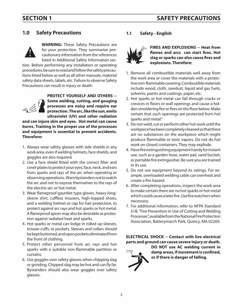
FIReS aND exPlOSIONS -- Heat from flames and arcs can start fires. Hot slag or sparks can also cause fires and explosions. Therefore:
1. Remove all combustible materials well away from the work area or cover the materials with a protec-tive non-flammable covering. Combustible materials include wood, cloth, sawdust, liquid and gas fuels, solvents, paints and coatings, paper, etc.
2. Hot sparks or hot metal can fall through cracks or crevices in floors or wall openings and cause a hid-den smoldering fire or fires on the floor below. Make certain that such openings are protected from hot sparks and metal.“
3. Do not weld, cut or perform other hot work until the workpiece has been completely cleaned so that there are no substances on the workpiece which might produce flammable or toxic vapors. Do not do hot work on closed containers. They may explode.
4. Have fire extinguishing equipment handy for instant use, such as a garden hose, water pail, sand bucket, or portable fire extinguisher. Be sure you are trained in its use.
5. Do not use equipment beyond its ratings. For ex-ample, overloaded welding cable can overheat and create a fire hazard.
6. After completing operations, inspect the work area to make certain there are no hot sparks or hot metal which could cause a later fire. Use fire watchers when necessary.
7. For additional information, refer to NFPA Standard 51B, "Fire Prevention in Use of Cutting and Welding Processes", available from the National Fire Protection Association, Batterymarch Park, Quincy, MA 02269.
elecTRIcal SHOcK -- contact with live electrical parts and ground can cause severe injury or death.
DO NOT use ac welding current in damp areas, if movement is confined, or if there is danger of falling.
SecTION 1 SaFeTY PRecauTIONS
1.0 Safety Precautions 1.1 Safety - english
6
SecTION 1 SaFeTY PRecauTIONS
1. Be sure the power source frame (chassis) is con-nected to the ground system of the input power.
2. Connect the workpiece to a good electrical ground.
3. Connect the work cable to the workpiece. A poor or missing connection can expose you or others to a fatal shock.
4. Use well-maintained equipment. Replace worn or damaged cables.
5. Keep everything dry, including clothing, work area,
cables, torch/electrode holder, and power source.
6. Make sure that all parts of your body are insulated from work and from ground.
7. Do not stand directly on metal or the earth while working in tight quarters or a damp area; stand on dry boards or an insulating platform and wear rubber-soled shoes.
8. Put on dry, hole-free gloves before turning on the power.
9. Turn off the power before removing your gloves.
10. Refer to ANSI/ASC Standard Z49.1 (listed on next page) for specific grounding recommendations. Do not mistake the work lead for a ground cable.
elecTRIc aND MagNeTIc FIelDS — May be dangerous. electric current flowing through any
conductor causes localized electric and Magnetic Fields (eMF). Weld-ing and cutting current creates eMF around welding cables and welding machines. Therefore:
1. Welders having pacemakers should consult their physician before welding. EMF may interfere with some pacemakers.
2. Exposure to EMF may have other health effects which are unknown.
3. Welders should use the following procedures to minimize exposure to EMF:
A. Route the electrode and work cables together. Secure them with tape when possible.
B. Never coil the torch or work cable around your body.
C. Do not place your body between the torch and work cables. Route cables on the same side of your body.
D. Connect the work cable to the workpiece as close as possible to the area being welded.
E. Keep welding power source and cables as far away from your body as possible.
FuMeS aND gaSeS -- Fumes and gases, can cause discomfort or harm, particularly in confined spaces. Do not breathe fumes and gases. Shield-ing gases can cause asphyxiation.
Therefore:
1. Always provide adequate ventilation in the work area by natural or mechanical means. Do not weld, cut, or gouge on materials such as galvanized steel, stain-less steel, copper, zinc, lead, beryllium, or cadmium unless positive mechanical ventilation is provided. Do not breathe fumes from these materials.
2. Do not operate near degreasing and spraying opera-tions. The heat or arc rays can react with chlorinated hydrocarbon vapors to form phosgene, a highly toxic gas, and other irritant gases.
3. If you develop momentary eye, nose, or throat irrita-tion while operating, this is an indication that ventila-tion is not adequate. Stop work and take necessary steps to improve ventilation in the work area. Do not continue to operate if physical discomfort persists.
4. Refer to ANSI/ASC Standard Z49.1 (see listing below) for specific ventilation recommendations.
7
SecTION 1 SaFeTY PRecauTIONS
5. WaRNINg: This product, when used for welding or cutting, produces fumes or gases which contain chemicals known to the State of california to cause birth defects and, in some cases, cancer. (california Health & Safety code §25249.5 et seq.)
cYlINDeR HaNDlINg -- cylinders, if mishandled, can rupture and violently release gas. Sudden rupture of cylin-der, valve, or relief device can injure or kill. Therefore:
1. Use the proper gas for the process and use the proper pressure reducing regulator designed to operate from the compressed gas cylinder. Do not use adap-tors. Maintain hoses and fittings in good condition. Follow manufacturer's operating instructions for mounting regulator to a compressed gas cylinder.
2. Always secure cylinders in an upright position by chain or strap to suitable hand trucks, undercarriages, benches, walls, post, or racks. Never secure cylinders to work tables or fixtures where they may become part of an electrical circuit.
3. When not in use, keep cylinder valves closed. Have valve protection cap in place if regulator is not con-nected. Secure and move cylinders by using suitable hand trucks. Avoid rough handling of cylinders.
4. Locate cylinders away from heat, sparks, and flames. Never strike an arc on a cylinder.
5. For additional information, refer to CGA Standard P-1, "Precautions for Safe Handling of Compressed Gases in Cylinders", which is available from Compressed Gas Association, 1235 Jefferson Davis Highway, Arlington, VA 22202.
eQuIPMeNT MaINTeNaNce -- Faulty or improperly maintained equipment can cause injury or death. Therefore:
1. Always have qualified personnel perform the installa-tion, troubleshooting, and maintenance work. Do not perform any electrical work unless you are qualified to perform such work.
2. Before performing any maintenance work inside a power source, disconnect the power source from the incoming electrical power.
3. Maintain cables, grounding wire, connections, power cord, and power supply in safe working order. Do not operate any equipment in faulty condition.
4. Do not abuse any equipment or accessories. Keep equipment away from heat sources such as furnaces, wet conditions such as water puddles, oil or grease, corrosive atmospheres and inclement weather.
5. Keep all safety devices and cabinet covers in position and in good repair.
6. Use equipment only for its intended purpose. Do not modify it in any manner.
aDDITIONal SaFeTY INFORMaTION -- For more information on safe practices for electric arc welding and cutting equip-ment, ask your supplier for a copy of "Precautions and Safe Practices for arc Welding, cutting and gouging", Form 52-529.
The following publications, which are available from the American Welding Society, 550 N.W. LeJuene Road, Miami, FL 33126, are recommended to you:
1. ANSI/ASC Z49.1 - "Safety in Welding and Cutting"
2. AWS C5.1 - "Recommended Practices for Plasma Arc Welding"
3. AWS C5.2 - "Recommended Practices for Plasma Arc Cutting"
4. AWS C5.3 - "Recommended Practices for Air Carbon Arc Gouging and Cutting"
8
SecTION 1 SaFeTY PRecauTIONS
5. AWS C5.5 - "Recommended Practices for Gas Tungsten Arc Welding“
6. AWS C5.6 - "Recommended Practices for Gas Metal Arc Welding"“
8. ANSI/AWS F4.1, "Recommended Safe Practices for Weld-ing and Cutting of Containers That Have Held Hazardous Substances."
MeaNINg OF SYMBOlS - as used throughout this manual: Means attention! Be alert! Your safety is involved.
Means immediate hazards which, if not avoided, will result in im-mediate, serious personal injury or loss of life.
Means potential hazards which could result in personal injury or loss of life.
Means hazards which could result in minor personal injury.
9
SecTION 1 SaFeTY PRecauTIONS
1.2 Safety - Spanish
aDVeRTeNcIa: estas Precauciones de Seguridad son para su protección. ellas hacen resumen de información prove-
niente de las referencias listadas en la sección "Información adicional Sobre la Seguridad". antes de hacer cualquier instalación o procedimiento de operación , asegúrese de leer y seguir las precaucio-nes de seguridad listadas a continuación así como también todo manual, hoja de datos de seguridad del material, calcomanias, etc. el no observar las Precauciones de Seguridad puede resultar en daño a la persona o muerte.
PROTeJaSe uSTeD Y a lOS DeMaS-- algunos procesos de soldadura, corte y ranurado son ruidosos y requiren protección para los oídos. el arco, como
el sol , emite rayos ultravioleta (uV) y otras radiaciones que pueden dañar la piel y los ojos. el metal caliente causa quemaduras. el entrenamiento en el uso propio de los equipos y sus procesos es esencial para prevenir accidentes. Por lo tanto:
1. utilice gafas de seguridad con protección a los lados siempre que esté en el área de trabajo, aún cuando esté usando careta de soldar, protector para su cara u otro tipo de protección.
2. use una careta que tenga el filtro correcto y lente para proteger sus ojos, cara, cuello, y oídos de las chispas y rayos del arco cuando se esté operando y observando las operaciones. alerte a todas las personas cercanas de no mirar el arco y no exponerse a los rayos del arco eléctrico o el metal fundido.
3. use guantes de cuero a prueba de fuego, camisa pesada de mangas largas, pantalón de ruedo liso, zapato alto al tobillo, y careta de soldar con capucha para el pelo, para proteger el cuerpo de los rayos y chispas calientes provenientes del metal fundido. en ocaciones un delantal a prueba de fuego es necesario para protegerse del calor radiado y las chispas.
4. chispas y partículas de metal caliente puede alojarse en las mangas enrolladas de la camisa , el ruedo del pantalón o los bolsillos. Mangas y cuellos deberán mantenerse abotonados, bolsillos al frente de la camisa deberán ser cerrados o eliminados.
5. Proteja a otras personas de los rayos del arco y chispas calientes con una cortina adecuada no-flamable como división.
6. use careta protectora además de sus gafas de segu-ridad cuando esté removiendo escoria o puliendo.
la escoria puede estar caliente y desprenderse con velocidad. Personas cercanas deberán usar gafas de seguridad y careta protectora.
FuegO Y exPlOSIONeS -- el calor de las flamas y el arco pueden ocacionar fuegos. escoria caliente y las chispas pueden causar fuegos y explosiones. Por lo tanto:
1. Remueva todo material combustible lejos del área de trabajo o cubra los materiales con una cobija a prueba de fuego. Materiales combustibles incluyen madera, ropa, líquidos y gases flamables, solventes, pinturas, papel, etc.
2. chispas y partículas de metal pueden introducirse en las grietas y agujeros de pisos y paredes cau-sando fuegos escondidos en otros niveles o espacios. asegúrese de que toda grieta y agujero esté cubierto para proteger lugares adyacentes contra fuegos.
3. No corte, suelde o haga cualquier otro trabajo rela-cionado hasta que la pieza de trabajo esté totalmente limpia y libre de substancias que puedan producir gases inflamables o vapores tóxicos. No trabaje dentro o fuera de contenedores o tanques cerrados. estos pueden explotar si contienen vapores inflamables.
4. Tenga siempre a la mano equipo extintor de fuego para uso instantáneo, como por ejemplo una manguera con agua, cubeta con agua, cubeta con arena, o extintor portátil. asegúrese que usted esta entrenado para su uso.
5. No use el equipo fuera de su rango de operación. Por ejemplo, el calor causado por cable sobrecarga en los cables de soldar pueden ocasionar un fuego.
6. Después de termirar la operación del equipo, inspec-cione el área de trabajo para cerciorarse de que las chispas o metal caliente ocasionen un fuego más tarde. Tenga personal asignado para vigilar si es necesario.
7. Para información adicional , haga referencia a la publicación NFPa Standard 51B, "Fire Prevention in use of cutting and Welding Processes", disponible a través de la National Fire Protection association, Batterymarch Park, Quincy, Ma 02269.
cHOQue elecTRIcO -- el contacto con las partes eléctricas energizadas y tierra puede causar daño severo o muerte. NO use soldadura de corriente alterna (ac) en áreas húmedas, de movimiento
confinado en lugares estrechos o si hay posibilidad de caer al suelo.
10
SecTION 1 SaFeTY PRecauTIONS
1. Asegúrese de que el chasis de la fuente de poder esté conectado a tierra através del sistema de elec-tricidad primario.
2. Conecte la pieza de trabajo a un buen sistema de tierra física.
3. Conecte el cable de retorno a la pieza de trabajo. Cables y conductores expuestos o con malas conex-iones pueden exponer al operador u otras personas a un choque eléctrico fatal.
4. Use el equipo solamente si está en buenas condi-ciones. Reemplaze cables rotos, dañados o con conductores expuestos.
5. Mantenga todo seco, incluyendo su ropa, el área de trabajo, los cables, antorchas, pinza del electrodo, y la fuente de poder.
6. Asegúrese que todas las partes de su cuerpo están insuladas de ambos, la pieza de trabajo y tierra.
7. No se pare directamente sobre metal o tierra mien-tras trabaja en lugares estrechos o áreas húmedas; trabaje sobre un pedazo de madera seco o una plataforma insulada y use zapatos con suela de goma.
8. Use guantes secos y sin agujeros antes de energizar el equipo.
9. Apage el equipo antes de quitarse sus guantes. 10. Use como referencia la publicación ANSI/ASC
Standard Z49.1 (listado en la próxima página) para recomendaciones específicas de como conectar el equipo a tierra. No confunda el cable de soldar a la pieza de trabajo con el cable a tierra.
caMPOS elecTRIcOS Y MagNeTI-cOS - Son peligrosos. la corriente eléctrica fluye através de cualquier conductor causando a nivel local cam-pos eléctricos y Magnéticos (eMF). las
corrientes en el área de corte y soldadura, crean eMF alrrededor de los cables de soldar y las maquinas. Por lo tanto: 1. Soldadores u Operadores que use marca-pasos para
el corazón deberán consultar a su médico antes de soldar. El Campo Electromagnético (EMF) puede interferir con algunos marca-pasos.
2. Exponerse a campos electromagnéticos (EMF) puede causar otros efectos de salud aún desconocidos.
3. Los soldadores deberán usar los siguientes proced-imientos para minimizar exponerse al EMF:
A. Mantenga el electrodo y el cable a la pieza de trabajo juntos, hasta llegar a la pieza que usted quiere soldar. Asegúrelos uno junto al otro con cinta adhesiva cuando sea posible.
B. Nunca envuelva los cables de soldar alrededor de su cuerpo.
C. Nunca ubique su cuerpo entre la antorcha y el cable, a la pieza de trabajo. Mantega los cables a un sólo lado de su cuerpo.
D. Conecte el cable de trabajo a la pieza de trabajo lo más cercano posible al área de la soldadura.
E. Mantenga la fuente de poder y los cables de soldar lo más lejos posible de su cuerpo.
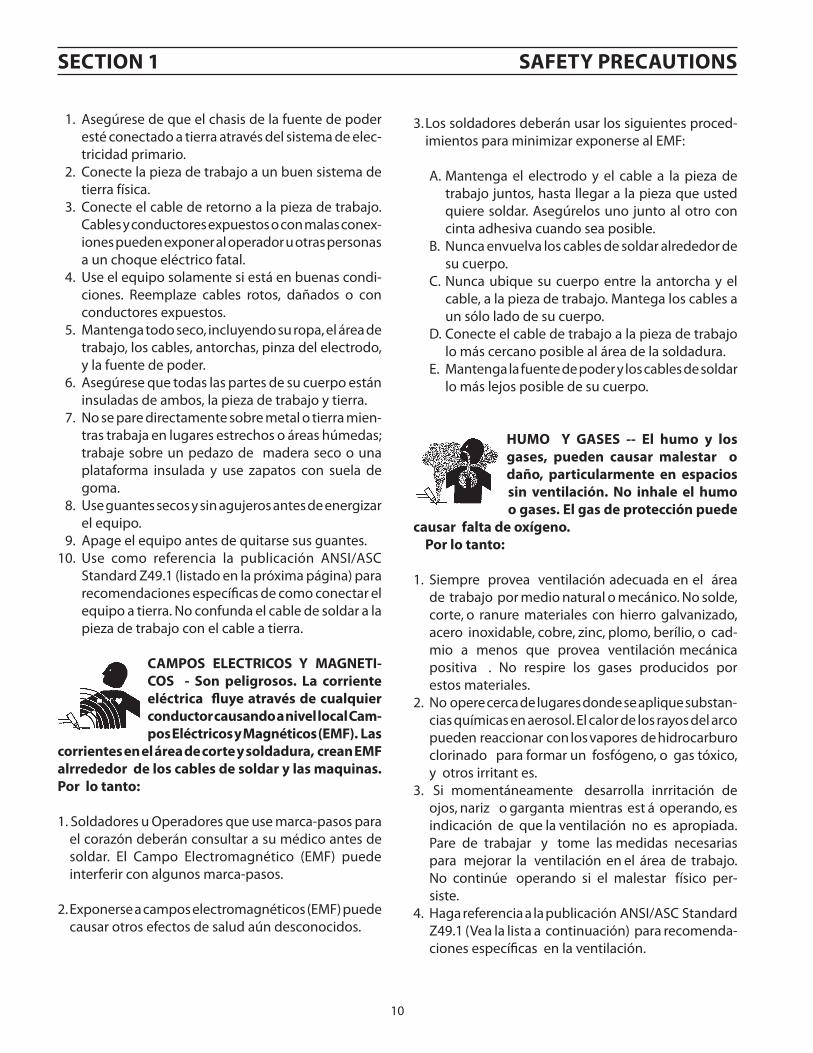
HuMO Y gaSeS -- el humo y los gases, pueden causar malestar o daño, particularmente en espacios sin ventilación. No inhale el humo o gases. el gas de protección puede
causar falta de oxígeno. Por lo tanto:
1. Siempre provea ventilación adecuada en el área de trabajo por medio natural o mecánico. No solde, corte, o ranure materiales con hierro galvanizado, acero inoxidable, cobre, zinc, plomo, berílio, o cad-mio a menos que provea ventilación mecánica positiva . No respire los gases producidos por estos materiales.
2. No opere cerca de lugares donde se aplique substan-cias químicas en aerosol. El calor de los rayos del arco pueden reaccionar con los vapores de hidrocarburo clorinado para formar un fosfógeno, o gas tóxico, y otros irritant es.
3. Si momentáneamente desarrolla inrritación de ojos, nariz o garganta mientras est á operando, es indicación de que la ventilación no es apropiada. Pare de trabajar y tome las medidas necesarias para mejorar la ventilación en el área de trabajo. No continúe operando si el malestar físico per-siste.
4. Haga referencia a la publicación ANSI/ASC Standard Z49.1 (Vea la lista a continuación) para recomenda-ciones específicas en la ventilación.
11
SecTION 1 SaFeTY PRecauTIONS
5. aDVeRTeNcIa-- este producto cuando se uti-liza para soldaduras o cortes, produce humos o gases, los cuales contienen químicos conocidos por el estado de cali-fornia de causar defectos en el nacimiento, o en algunos casos, cancer. (california Health & Safety code §25249.5 et seq.)
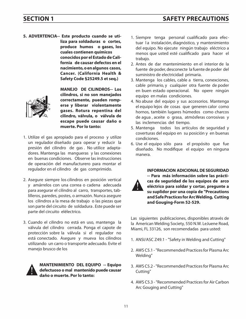
MaNeJO De cIlINDROS-- los cilindros, si no son manejados correctamente, pueden romp-erse y liberar violentamente gases. Rotura repentina del cilindro, válvula, o válvula de escape puede causar daño o muerte. Por lo tanto:
1. Utilize el gas apropiado para el proceso y utilize un regulador diseñado para operar y reducir la presión del cilindro de gas . No utilice adapta-dores. Mantenga las mangueras y las conexiones en buenas condiciones. Observe las instrucciones de operación del manufacturero para montar el regulador en el cilindro de gas comprimido.
2. Asegure siempre los cilindros en posición vertical y amárrelos con una correa o cadena adecuada para asegurar el cilindro al carro, transportes, tab-lilleros, paredes, postes, o armazón. Nunca asegure los cilindros a la mesa de trabajo o las piezas que son parte del circuito de soldadura . Este puede ser parte del circuito elélectrico.
3. Cuando el cilindro no está en uso, mantenga la válvula del cilindro cerrada. Ponga el capote de protección sobre la válvula si el regulador no está conectado. Asegure y mueva los cilindros utilizando un carro o transporte adecuado. Evite el manejo brusco de los
MaNTeNIMIeNTO Del eQuIPO -- equipo defectuoso o mal mantenido puede causar daño o muerte. Por lo tanto:
1. Siempre tenga personal cualificado para efec-tuar l a instalación, diagnóstico, y mantenimiento del equipo. No ejecute ningún trabajo eléctrico a menos que usted esté cualificado para hacer el trabajo.
2. Antes de dar mantenimiento en el interior de la fuente de poder, desconecte la fuente de poder del suministro de electricidad primaria.
3. Mantenga los cables, cable a tierra, conexciones, cable primario, y cualquier otra fuente de poder en buen estado operacional. No opere ningún equipo en malas condiciones.
4. No abuse del equipo y sus accesorios. Mantenga el equipo lejos de cosas que generen calor como hornos, también lugares húmedos como charcos de agua , aceite o grasa, atmósferas corrosivas y las inclemencias del tiempo.
5. Mantenga todos los artículos de seguridad y coverturas del equipo en su posición y en buenas condiciones.
6. Use el equipo sólo para el propósito que fue diseñado. No modifique el equipo en ninguna manera.
INFORMacION aDIcIONal De SeguRIDaD -- Para más información sobre las prácti-cas de seguridad de los equipos de arco eléctrico para soldar y cortar, pregunte a su suplidor por una copia de "Precautions and Safe Practices for arc Welding, cutting and gouging-Form 52-529.
Las siguientes publicaciones, disponibles através de la American Welding Society, 550 N.W. LeJuene Road, Miami, FL 33126, son recomendadas para usted:
1. ANSI/ASC Z49.1 - "Safety in Welding and Cutting"
2. AWS C5.1 - "Recommended Practices for Plasma Arc Welding"
3. AWS C5.2 - "Recommended Practices for Plasma Arc Cutting"
4. AWS C5.3 - "Recommended Practices for Air Carbon Arc Gouging and Cutting"
12
SecTION 1 SaFeTY PRecauTIONS
SIgNIFIcaDO De lOS SIMBOlOS -- Según usted avanza en la lec-tura de este folleto: los Símbolos Significan ¡atención! ¡esté alerta! Se trata de su seguridad.
Significa riesgo inmediato que, de no ser evadido, puede resultar inmediatamente en serio daño personal o la muerte.
Significa el riesgo de un peligro po-tencial que puede resultar en serio daño personal o la muerte.
Significa el posible riesgo que puede resultar en menores daños a la persona.
13
SecTION 1 SaFeTY PRecauTIONS1.3 Safety - French
INceNDIeS eT exPlOSIONS -- la chaleur provenant des flammes ou de l'arc peut provoquer un incendie. le laitier incandescent ou les étincelles
peuvent également provoquer un incendie ou une explosion. Par conséquent :
1. Éloignez suffisamment tous les matériaux combus-tibles de l'aire de travail et recouvrez les matériaux avec un revêtement protecteur ininflammable. les matériaux combustibles incluent le bois, les vête-ments, la sciure, le gaz et les liquides combustibles, les solvants, les peintures et les revêtements, le papier, etc.
2. les étincelles et les projections de métal incandescent peuvent tomber dans les fissures dans les planchers ou dans les ouvertures des murs et déclencher un incendie couvant à l'étage inférieur assurez-vous que ces ouvertures sont bien protégées des étincelles et du métal incandescent.
3. N'exécutez pas de soudure, de coupe ou autre travail à chaud avant d'avoir complètement nettoyé la surface de la pièce à traiter de façon à ce qu'il n'ait aucune substance présente qui pourrait produire des vapeurs inflammables ou toxiques. N'exécutez pas de travail à chaud sur des contenants fermés car ces derniers pourraient exploser.
4. assurez-vous qu'un équipement d'extinction d'incendie est disponible et prêt à servir, tel qu'un tuyau d'arrosage, un seau d'eau, un seau de sable ou un extincteur portatif. assurez-vous d'être bien instruit par rapport à l'usage de cet équipement.
5. assurez-vous de ne pas excéder la capacité de l'équipement. Par exemple, un câble de soudage sur-chargé peut surchauffer et provoquer un incendie.
6. une fois les opérations terminées, inspectez l'aire de travail pour assurer qu'aucune étincelle ou projec-tion de métal incandescent ne risque de provoquer un incendie ultérieurement. employez des guetteurs d'incendie au besoin.
7. Pour obtenir des informations supplémentaires, consultez le NFPa Standard 51B, "Fire Prevention in use of cutting and Welding Processes", disponible au National Fire Protection association, Batterymarch Park, Quincy, Ma 02269.
cHOc ÉlecTRIQue -- le contact avec des pièces électriques ou les pièces de mise à la terre sous tension peut causer des blessures graves ou mor-telles. Ne PaS utiliser un courant de
soudage c.a. dans un endroit humide, en espace restreint ou si un danger de chute se pose.
aVeRTISSeMeNT : ces règles de sécurité ont pour but d'assurer votre protection. Ils récapitulent les informations de précaution provenant des références
dans la section des Informations de sécurité sup-plémentaires. avant de procéder à l'installation ou d'utiliser l'unité, assurez-vous de lire et de suivre les précautions de sécurité ci-dessous, dans les manuels, les fiches d'information sur la sécurité du matériel et sur les étiquettes, etc. Tout défaut d'observer ces précautions de sécurité peut entraîner des blessures
graves ou mortelles.
PROTÉgeZ-VOuS -- les processus de soudage, de coupage et de gougeage
produisent un niveau de bruit élevé et exige l'emploi d'une protection auditive. l'arc, tout comme le soleil, émet des rayons ultraviolets en plus d'autre rayons qui peuvent causer des blessures à la peau et les yeux. le métal incandescent peut causer des brûlures. une formation reliée à l'usage des proces-sus et de l'équipement est essentielle pour prévenir les accidents. Par conséquent: 1. Portez des lunettes protectrices munies d'écrans la-
téraux lorsque vous êtes dans l'aire de travail, même si vous devez porter un casque de soudeur, un écran facial ou des lunettes étanches.
2. Portez un écran facial muni de verres filtrants et de plaques protectrices appropriées afin de protéger vos yeux, votre visage, votre cou et vos oreilles des étincelles et des rayons de l'arc lors d'une opération ou lorsque vous observez une opération. avertissez les personnes se trouvant à proximité de ne pas regarder l'arc et de ne pas s'exposer aux rayons de l'arc électrique ou le métal incandescent.
3. Portez des gants ignifugiés à crispin, une chemise épaisse à manches longues, des pantalons sans rebord et des chaussures montantes afin de vous protéger des rayons de l'arc, des étincelles et du métal incandescent, en plus d'un casque de soudeur ou casquette pour pro-téger vos cheveux. Il est également recommandé de porter un tablier ininflammable afin de vous protéger des étincelles et de la chaleur par rayonnement.
4. les étincelles et les projections de métal incandescent risquent de se loger dans les manches retroussées, les rebords de pantalons ou les poches. Il est recommandé de garder boutonnés le col et les manches et de porter des vêtements sans poches en avant.
5. Protégez toute personne se trouvant à proximité des étincelles et des rayons de l'arc à l'aide d'un rideau ou d'une cloison ininflammable.
6. Portez des lunettes étanches par dessus vos lunettes de sécurité lors des opérations d'écaillage ou de meulage du laitier. les écailles de laitier incandescent peuvent être projetées à des distances considérables. les per-sonnes se trouvant à proximité doivent également porter des lunettes étanches par dessus leur lunettes de sécurité.
14
SecTION 1 SaFeTY PRecauTIONS
3. Les soudeurs doivent suivre les procédures suivantes pour minimiser l'exposition aux champs électriques et magnétiques :
A. Acheminez l'électrode et les câbles de masse ensemble. Fixez-les à l'aide d'une bande adhésive lorsque possible.
B. Ne jamais enrouler la torche ou le câble de masse autour de votre corps.
C. Ne jamais vous placer entre la torche et les câbles de masse. Acheminez tous les câbles sur le même côté de votre corps.
D. Branchez le câble de masse à la pièce à traiter le plus près possible de la section à souder.
E. Veillez à garder la source d'alimentation pour le soudage et les câbles à une distance appropriée de votre corps.
leS VaPeuRS eT leS gaZ -- peuvent causer un malaise ou des dommages corporels, plus particulièrement dans les espaces restreints. Ne respirez pas les vapeurs et les gaz. le gaz de protec-tion risque de causer l'asphyxie. Par conséquent :
1. Assurez en permanence une ventilation adéquate dans l'aire de travail en maintenant une ventila-tion naturelle ou à l'aide de moyens mécanique. N'effectuez jamais de travaux de soudage, de coup-age ou de gougeage sur des matériaux tels que l'acier galvanisé, l'acier inoxydable, le cuivre, le zinc, le plomb, le berylliym ou le cadmium en l'absence de moyens mécaniques de ventilation efficaces. Ne respirez pas les vapeurs de ces matériaux.
2. N'effectuez jamais de travaux à proximité d'une opération de dégraissage ou de pulvérisation. Lorsque la chaleur
ou le rayonnement de l'arc entre en contact avec les vapeurs d'hydrocarbure chloré, ceci peut déclencher la formation de phosgène ou d'autres gaz irritants, tous extrêmement toxiques.
3. Une irritation momentanée des yeux, du nez ou de la gorge au cours d'une opération indique que la ven-tilation n'est pas adéquate. Cessez votre travail afin de prendre les mesures nécessaires pour améliorer la ventilation dans l'aire de travail. Ne poursuivez pas l'opération si le malaise persiste.
4. Consultez ANSI/ASC Standard Z49.1 (à la page suivante) pour des recommandations spécifiques concernant la ventilation.
1. Assurez-vous que le châssis de la source d'alimentation est branché au système de mise à la terre de l'alimentation d'entrée.
2. Branchez la pièce à traiter à une bonne mise de terre électrique.
3. Branchez le câble de masse à la pièce à traiter et assurez une bonne connexion afin d'éviter le risque de choc électrique mortel.
4. Utilisez toujours un équipement correctement entretenu. Remplacez les câbles usés ou endom-magés.
5. Veillez à garder votre environnement sec, incluant les vêtements, l'aire de travail, les câbles, le porte-électrode/torche et la source d'alimentation.
6. Assurez-vous que tout votre corps est bien isolé de la pièce à traiter et des pièces de la mise à la terre.
7. Si vous devez effectuer votre travail dans un espace restreint ou humide, ne tenez vous pas directe-ment sur le métal ou sur la terre; tenez-vous sur des planches sèches ou une plate-forme isolée et portez des chaussures à semelles de caoutchouc.
8. Avant de mettre l'équipement sous tension, isolez vos mains avec des gants secs et sans trous.
9. Mettez l'équipement hors tension avant d'enlever vos gants.
10. Consultez ANSI/ASC Standard Z49.1 (listé à la page suivante) pour des recommandations spéci-fiques concernant les procédures de mise à la terre. Ne pas confondre le câble de masse avec le câble de mise à la terre.
cHaMPS ÉlecTRIQueS eT MagNÉ-TIQueS — comportent un risque de danger. le courant électrique qui passe dans n'importe quel con-ducteur produit des champs élec-
triques et magnétiques localisés. le soudage et le courant de coupage créent des champs électriques et magnétiques autour des câbles de soudage et l'équipement. Par conséquent :
1. Un soudeur ayant un stimulateur cardiaque doit consulter son médecin avant d'entreprendre une opération de soudage. Les champs électriques et magnétiques peuvent causer des ennuis pour cer-tains stimulateurs cardiaques.
2. L'exposition à des champs électriques et magné-tiques peut avoir des effets néfastes inconnus pour la santé.
15
SecTION 1 SaFeTY PRecauTIONS
1. Efforcez-vous de toujours confier les tâches d'installation, de dépannage et d'entretien à un personnel qualifié. N'effectuez aucune réparation électrique à moins d'être qualifié à cet effet.
2. Avant de procéder à une tâche d'entretien à l'intérieur de la source d'alimentation, débranchez l'alimentation électrique.
3. Maintenez les câbles, les fils de mise à la terre, les branchements, le cordon d'alimentation et la source d'alimentation en bon état. N'utilisez jamais un équi-pement s'il présente une défectuosité quelconque.
4. N'utilisez pas l'équipement de façon abusive. Gardez l'équipement à l'écart de toute source de chaleur, notamment des fours, de l'humidité, des flaques d'eau, de l'huile ou de la graisse, des atmosphères corrosives et des intempéries.
5. Laissez en place tous les dispositifs de sécurité et tous les panneaux de la console et maintenez-les en bon état.
6. Utilisez l'équipement conformément à son usage prévu et n'effectuez aucune modification.
INFORMaTIONS SuPPlÉMeNTaIReS Rela-TIVeS À la SÉcuRITÉ -- Pour obtenir de l'information supplémentaire sur les règles de sécurité à observer pour l'équipement de soudage à l'arc électrique et le coupage, demandez un exemplaire du livret "Precau-tions and Safe Practices for arc Welding, cutting and gouging", Form 52-529.
Les publications suivantes sont également recomman-dées et mises à votre disposition par l'American Welding Society, 550 N.W. LeJuene Road, Miami, FL 33126 :1. ANSI/ASC Z49.1 - "Safety in Welding and Cutting"2. AWS C5.1 - "Recommended Practices for Plasma Arc
Welding"3. AWS C5.2 - "Recommended Practices for Plasma Arc
Cutting"4. AWS C5.3 - "Recommended Practices for Air Carbon
Arc Gouging and Cutting"
5. aVeRTISSeMeNT : ce produit, lorsqu'il est utilisé dans une opération de soudage ou de coupage, dégage des vapeurs ou des gaz contenant des chimiques consi-déres par l'état de la californie comme étant une cause des malformations congénitales et dans certains cas, du cancer. (california Health & Safety code §25249.5 et seq.)
MaNIPulaTION DeS cYlINDReS -- la manipulation d'un cylindre, sans observer les précautions néces-saires, peut produire des fissures et un échappement dangereux des gaz. une brisure soudaine du cylin-
dre, de la soupape ou du dispositif de surpression peut causer des blessures graves ou mortelles. Par conséquent :
1. Utilisez toujours le gaz prévu pour une opération et le détendeur approprié conçu pour utilisation sur les cylindres de gaz comprimé. N'utilisez jamais d'adaptateur. Maintenez en bon état les tuyaux et les raccords. Observez les instructions d'opération du fabricant pour assembler le détendeur sur un cylindre de gaz comprimé.
2. Fixez les cylindres dans une position verticale, à l'aide d'une chaîne ou une sangle, sur un chariot manuel, un châssis de roulement, un banc, un mur, une col-onne ou un support convenable. Ne fixez jamais un cylindre à un poste de travail ou toute autre dispositif faisant partie d'un circuit électrique.
3. Lorsque les cylindres ne servent pas, gardez les soupapes fermées. Si le détendeur n'est pas bran-ché, assurez-vous que le bouchon de protection de la soupape est bien en place. Fixez et déplacez les cylindres à l'aide d'un chariot manuel approprié. Toujours manipuler les cylindres avec soin.
4. Placez les cylindres à une distance appropriée de toute source de chaleur, des étincelles et des flammes. Ne jamais amorcer l'arc sur un cylindre.
5. Pour de l'information supplémentaire, consultez CGA Standard P-1, "Precautions for Safe Handling of Com-pressed Gases in Cylinders", mis à votre disposition par le Compressed Gas Association, 1235 Jefferson Davis Highway, Arlington, VA 22202.
eNTReTIeN De l'ÉQuIPeMeNT -- un équipe-ment entretenu de façon défectueuse ou inadéquate peut causer des blessures graves ou mortelles. Par conséquent :
16
SecTION 1 SaFeTY PRecauTIONS
SIgNIFIcaTION DeS SYMBOleSce symbole, utilisé partout dans ce manuel, signifie "attention" ! Soyez vigilant ! Votre sécurité est en jeu.
Signifie un danger immédiat. la situation peut entraîner des blessures graves ou mortelles.
Signifie un danger potentiel qui peut entraîner des blessures graves ou mortelles.
Signifie un danger qui peut entraîner des blessures corporelles mineures.
DANGER
AVERTISSEMENT
ATTENTION
class a equipment is not intended for use in residential locations wherethe electrical power is provided by the public low-voltage sup-ply system.There may be potential difficulties in ensuring electromag-neticcompatibility of class a equipment in those locations, due to con-ductedas well as radiated disturbances.
cauTION
This product is solely intended for plasma cutting.cauTION
Do not dispose of electrical equipment together with normal waste! In observance of european Directive 2002/96/ec on Waste electrical and electronic equipment and its implementation in accordance with na-tional law, electrical equipment that has reached the end of its life must be collected separately and returned to an environmentally compatible recycling facility. as the owner of the equipment, you should get infor-mation on approved collection systems from our local representative.By applying this european Directive you will improve the environment and human health!
cauTION
17
ESP-150 PlasmarcTM SystemThis versatile, all encompassed heavy duty water cooled plasma cutting and gouging system is ideal for manual and mechanized applications.
SpecificationsInput Current and Input Voltage at Rated Load ...............................................112/56/45 amps, 230/460/575 Vac, 60 Hz, 3 PhOutput Rating 90% duty cycle .........................................................................150 amps @ 120 V 100% duty cycle ......................................................................140 amps @ 120 VOpen circuit Voltage ........................................................................................ 370 vdcDimensions ............................................................................ w = 21.75 in. (552mm) ..................................................................................................h = 31.5 in. (800mm) ...................................................................................................d = 40 in. (1016mm)Weight ..................................................................................................766 lbs. (348 kg)
SecTION 2 DeScRIPTION
Duty cycleThe duty cycle refers to the time as a percentage of a ten-minute period that you can weld at a cer tain load without overloading. The duty cycle is valid for 40°C.
Enclosure classThe IP code indicates the enclosure class, i. e. the degree of protection against penetration by solid objects or water.
2.0 Description
The power source is supplied with coolant and instruction manual.
2.1 equipment
18
How to OrderThe ESP-150 package includes console, PT-26 torch with leather sheath, torch spare parts kit, 25 ft. or 50 ft. work cable, TR-21 truck with dual cylinder rack, regulators and gas hoses and torch coolant.
ESAB can provide you with all necessary welding protection and accessories.
NOTE: Contact your ESAB Representative to substitute console.
Optional Accessories150 amp Spare Parts Kit .............................................................. 0558002864Remote Hand Switch Permits remote starting and stopping of cutting process; used primarily for mechanized cutting .........................................207560025 ft. leather Sheath* Protects torch leads from abrasion and molten metal; particularly .... recommended for plasma gouging ............................................. 055800292150 ft. leather Sheath* ................................................................... 0558002922Plasma Flow Measuring Kit This valuable troubleshooting tool allows measurement of the .......... actual plasma gas flow through the torch ........................................ 19765Plasma Torch Head Protector For gouging ................................................................................................. 20806Trigger latch Kit (FactoryInstalledOnly) .................................................................. 0588000939
Purity Required N2 - 99% min., Air - clean and dry
PT-26 Technical Specifications (Shield gas)
Type N2 or Air
Pressure 100 psig (6.9 bar) maximum
Flow 200 cfh (5.66 M3/h) @ 85 psig (5.86 bar)
Purity Required Nitrogen - 99% minimum, Air - clean and dry
Figure 1 - PT-26 In-line Torch Dimensions
2”(50.8)
16.5”(419mm)
21
eSP-150 MaNual PlaSMa cuTTINg PacKageS
aIR PacKageS
ar/H2 PacKageS
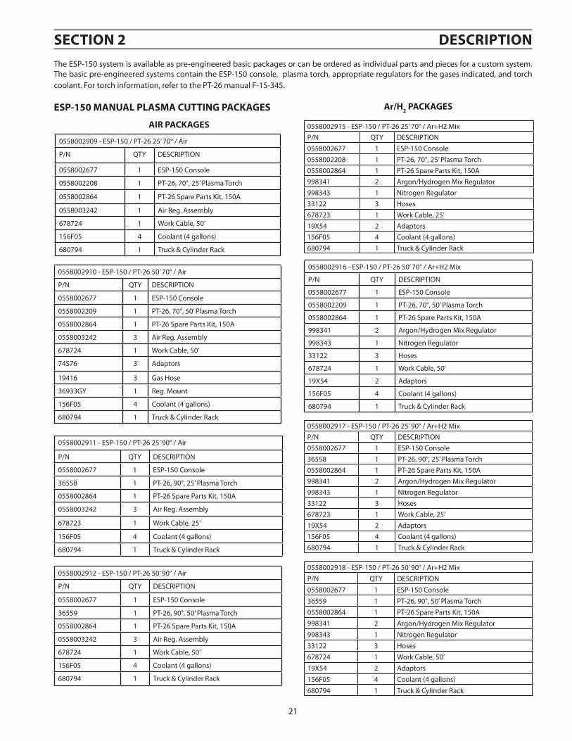
The ESP-150 system is available as pre-engineered basic packages or can be ordered as individual parts and pieces for a custom system. The basic pre-engineered systems contain the ESP-150 console, plasma torch, appropriate regulators for the gases indicated, and torch coolant. For torch information, refer to the PT-26 manual F-15-345.
Proper installation can contribute materially to satisfactory and trouble-free operation of the cutting outfit. Each step in this section should be studied carefully and followed as closely as possible.
3.1 Inspection and Placement
1. Having removed the shipping container, and before removing the skid, inspect for evidence of concealed damage which may not have been apparent upon receipt of the unit. Notify the carrier of any defects or damage at once.
2. Check the container for any loose parts. Check air passages on rear panel of cabinet for any packing materials that may obstruct air flow through the power supply.
The ESP-150 Power Source is equipped with one lifting eye that enables hoisting the unit. Be sure the lifting device has adequate capacity to lift the unit safely. Refer to the SPECIFICATIONS for the unit weight.
3. Mount the components of the TR-21 Truck Kit to the unit as covered by Form F-14-413 packed with the truck kit.
4. The machine components are maintained at proper operating tempera-tures by forced air which is drawn through the front panel louvers and holes in the base and out the rear panel by a heavy-duty fan. Locate this machine in an open area where air can circulate freely through the open-ings. Leave at least two feet of clearance between the unit and wall or other obstruction. The area around the unit should be relatively free of dust, fumes and excessive heat. (Installingorplacinganytypeoffilteringdevicewill restrict thevolumeof intakeair, therebysubjectingthepowersourceinternalcomponentstooverheating.Useofanytypeoffilterdevicevoidsthewarranty.)
5. A source of clean, dry air that supplies a minimum of 250cfh (7.08 M3H at 110 psig) is required for the cutting operation. The air supply should not exceed 150psig (10.3 bars) - maximum inlet pressure rating of the filter regulator supplied with the package.
Precautionary measures should be taken to provide maximum protection against electrical shock. Be sure that all power is off by opening the line (wall) disconnect switch and unplug the power cord to the unit when primary electrical connections are made to the power supply.
elecTRIc SHOcK caN KIll! Precaution-ary measures should be taken to provide maximum protection against electric shock. Be sure that all power is off by opening the line (wall) disconnect switch and by unplugging the power cord to the unit when connections are made inside of the power source.
SecTION 3 INSTallaTION
This product is intended for industrial use. In a domestic environment this product maycause radio interference. It is the user's responsibility to take adequate precautions.
cauTION
24
3.2 Primary Input electrical connections
1. A line (wall) disconnect switch, with fuse or circuit breakers, should be provided at the main power panel. See Fig. 3. The primary power leads should be insulated copper conductors, and include three power leads and one ground wire. The wires may be heavy rubber covered cable, or may be run in a solid or flexible conduit. Refer to Table 1 for recommended input conductors and line fuse sizes.
It is of the utmost importance that the chassis be connected to an approved electrical ground to prevent accidental shocking. Take care not to connect the ground wire to any of the primary leads.
Precautionary measures should be taken to provide maximum protection against electrical shock. Be sure that all power is off by opening the line (wall) disconnect switch and unplug the power cord to the unit use proper lock out safety procedures when making primary electrical connec-tions to the power supply.
FIg 3. Typical Installation - user Supplied 3 Phase Fused Power Disconnect Box with Recepticle
Table 3-1. Input conductor and line Fuse Size Recommendations
Sizes per National Electrical Code for 75o rated conductors @ 30oC ambient. Not more than three conductors in raceway or cable. Local codes should be followed if they specify sizes other than those listed above.
SecTION 3 INSTallaTION
25
elecTRIc SHOcK caN KIll! Precaution-ary measures should be taken to provide maximum protection against electric shock. Be sure that all power is off by opening the line (wall) disconnect switch by unplugging the power cord to the unit or use proper lock out safety procedures when making connections inside of the power source.
Fig. 4aInput Terminal Board
230/460/575 Vac Models
230 Vac Configuration
2. 60 Hz Models - As shipped from the factory, the ESP-150 is configured for the highest connectable voltage. If using other input voltages, the links on the terminal board (TB) inside the unit must be repositioned for the appropriate input voltage. See the figures 4a,b & c input voltage configurations. To gain access to the terminal board, open the access panel on the left side.
Fig. 4bInput Terminal Board
230/460/575 Vac Models
460 Vac Configuration
Fig. 4cInput Terminal Board
230/460/575 Vac Models
575 Vac Configuration(Factory Supplied)
SecTION 3 INSTallaTION
26
Before making any connections to the power source output terminals, make sure that all primary input power to the machine is de-energized (off) at the dis-connect switch.
3. Safety codes specify that the Power Cable GROUND wire be the last to break connection should the cable be pulled out of the unit. Be sure to cut and strip wire as shown in Figure 6.
4. Thread the input conductor cable from the wall disconnect switch through the strain relief in the rear panel of the main contactor (MC). Connect the primary power leads to the main contactor terminals (see Figure 7) using UL listed pressure wire connectors. Also connect the ground wire to the stud provided on the chassis base inside the left-rear of the cabinet. Secure the input cable by tightening the strain relief coupling.
5. Recheck all connections to make sure that they are tight, well insulated, and the proper connection has been made. Then close access panel and reinstall fasteners.
a poor connection or failure to connect work cable to workpiece can result in fatal shock.
Failure to connect the workpiece to earth ground will result in the opening of FuSe F3 and cIRcuIT BReaKeR cB1, disabling the console.
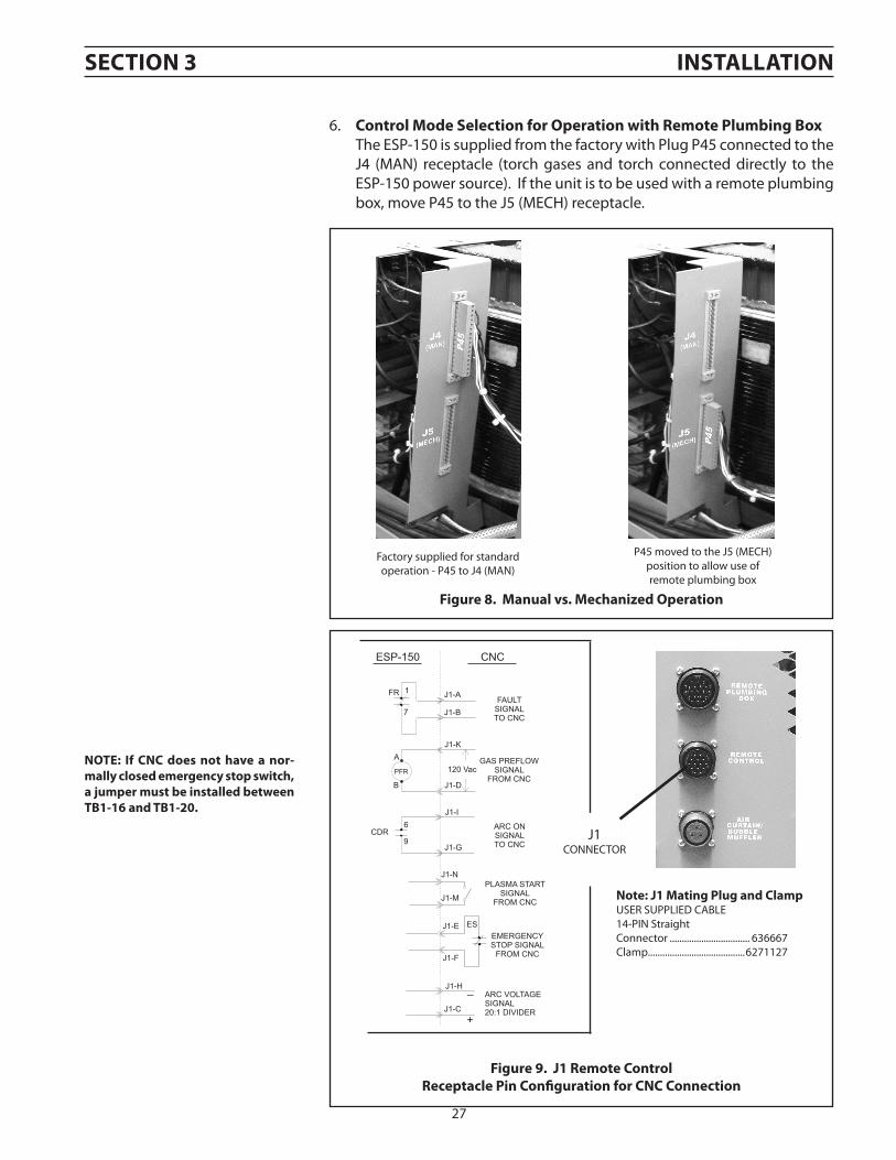
Figure 9. J1 Remote control Receptacle Pin configuration for cNc connection
6. control Mode Selection for Operation with Remote Plumbing Box The ESP-150 is supplied from the factory with Plug P45 connected to the
J4 (MAN) receptacle (torch gases and torch connected directly to the ESP-150 power source). If the unit is to be used with a remote plumbing box, move P45 to the J5 (MECH) receptacle.
Factory supplied for standardoperation - P45 to J4 (MAN)
P45 moved to the J5 (MECH)position to allow use ofremote plumbing box
NOTe: If cNc does not have a nor-mally closed emergency stop switch, a jumper must be installed between TB1-16 and TB1-20.
Figure 8. Manual vs. Mechanized Operation
SecTION 3 INSTallaTION
28
MaKe SuRe POWeR SWITcH ON cONSOle IS IN OFF POSITION aND PRIMaRY INPuT POWeR IS De-eNeRgIZeD.WaRNINg
3.3 Voltage Divider adjustment
Potentiometer
It may be necessary to adjust the Voltage Divider or VDR to match the particular height control system. There are two default settings for the PowerCut models as shipped from the factory:
1. Place ohm meter leads between W2 (arc voltage) & W3 (work). Adjust R1 to achieve the desired divide ratio for the particular height control system used. For example:
• STANDARD UNITS (Non-CE): 750 ohms (21:1)
• 16:1 ratio 1000 ohms • 18:1 ratio 882 ohms
• 21:1 ratio 750 ohms• 20:1 ratio 789 ohms
2. If desired, additional minor adjustments of the VDR potentiometer may be made. Any adjustments should be performed by a qualified technician.
• CE UNITS (Europe): 789 ohms (20:1)
If the height control system does not match the factory default setting, matching can be accomplished by ad-justing the VDR potentiometer.
SecTION 3 INSTallaTION
29
3.4 Torch connections
1. Open top front cover to gain access to the torch connections.(Fig. 10)2. Thread the five service lines (gas, power, and switch lead) of the PT-26 torch through bushing at upper left corner of the
front panel and connect them to the matching fittings on output terminal. Hose connections should be wrench-tight. Make sure plug of the switch lead is firmly locked in place. Then close and reinstall the hinged cover.
a. If a PT-26 In-line Torch is being used in a mechanized installation where only an arc start signal is required, connect the optional Remote Hand Switch, ESAB part number 2075600, to the Torch Switch Receptacle on the hook-up panel in the front of the ESP-150 console. Fig. 11.
b. If a PT-26 In-line Torch is being used in a mechanized installation with a CNC device, see Fig. 9 for Remote Control Receptacle I/O signal pin configuration and Fig. 8 for Control Mode Selection instructions.
Water OuT (-)(Torch)
Water IN (+)(Pilot arc)
Shieldgas
4
2
++ --
Fig. 12 - Interconnection Diagram - Front of eSP-150
Plasma/Start gas
Torch SwitchReceptacle
3
5
Fig. 11 - For Mechanized applications using a shielded in-line torch, remove the rubber grommet slide body through sheet metal front of ESP-150 and tighten with locknut.
Fig. 10 - For manual torch applications, pass the service connections through the rubber grommet in the front of ESP-150 and make connections as shown.
12
3
4
5
1
SecTION 3 INSTallaTION
30
3.5 gas Supply connections
1. Connect the gas supplies. The cylinders may be placed and secured on the cylinder rack of the truck. Before connecting the regulators, be sure to read, understand, and follow all instructions packed with each regulator.
2. Connect the gas hoses to the regulators and to the proper fittings (Adaptors: 74S76, Air; 19X54, Ar/H2) on the rear panel of the ESP-150. Connections should be wrench tight including those that are plugged. (Fig. 14)
(3) air Filter RegulatorsP/N-36932
Select ONlY ONe (1) Inlet connection,
NeVeR BOTH, when selecting Plasma
gas
Fig. 13 - air Filter Regulator connections
Fig. 14 - gas connections
SecTION 3 INSTallaTION
31
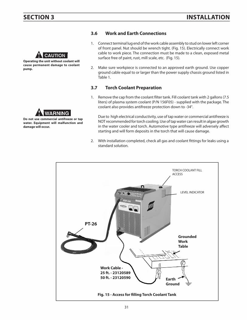
3.6 Work and earth connections
1. Connect terminal lug end of the work cable assembly to stud on lower left corner of front panel. Nut should be wrench tight. (Fig. 15). Electrically connect work cable to work piece. The connection must be made to a clean, exposed metal surface free of paint, rust, mill scale, etc. (Fig. 15).
2. Make sure workpiece is connected to an approved earth ground. Use copper ground cable equal to or larger than the power supply chassis ground listed in Table 1.
3.7 Torch coolant Preparation
1. Remove the cap from the coolant filter tank. Fill coolant tank with 2 gallons (7.5 liters) of plasma system coolant (P/N 156F05) - supplied with the package. The coolant also provides antifreeze protection down to -34°.
Due to high electrical conductivity, use of tap water or commercial antifreeze is NOT recommended for torch cooling. Use of tap water can result in algae growth in the water cooler and torch. Automotive type antifreeze will adversely affect starting and will form deposits in the torch that will cause damage.
2. With installation completed, check all gas and coolant fittings for leaks using a standard solution.
TORCH COOLANT FILL ACCESS
Fig. 15 - access for filling Torch coolant Tank
Operating the unit without coolant will cause permanent damage to coolant pump.
Do not use commercial antifreeze or tap water. equipment will malfunction and damage will occur.
PT-26
groundedWorkTable
earthground
Work cable - 25 ft. - 2312058950 ft. - 23120590
LEVEL INDICATOR
SecTION 3 INSTallaTION
32
SecTION 3 INSTallaTION
33
1 Topping up the coolant2 Level indicator for the coolant3 Connection for return cable4 Ampere and Voltmeter5 Connection for torch6 Mains voltage switch 7 Switch for gas 8 Current setting control9 Indicator lamps
1
2
3
4
5
6
7
8 9
SecTION 4 OPeRaTION
4.0 Operation
This section provides descriptions of the power source controls and general operating procedures plus, some tips on cut quality.
4.1 controls and Indicators
34
The status lights located on the front of the top lid of the ESP-150 console provide the conditions of the circuitry during a normal plasma arc cutting operation. By knowing the proper sequencing of events and by observing the status lights one can troubleshoot the console in a short time to minimize downtime.
None of these lights will function unless proper input voltage is applied with the links on the input terminal board (TB) properly connected for the input voltage; the ON-OFF power switch is ON; and the top lid of the console is closed firmly.
The following are the functions of each light:
POWeR (ROS) — Energizes power to the Fan, Water Cooler and Control Circuitry. This readies the unit for operation.
gaS MODe (OSS) — CUT - Allows for setup of cut gas pressure and flow; START/SHIELD - allows setup of start and shield gas pressure and flow; and OPERATE - posi-tion to use for cutting operations.
cuRReNT cONTROl — Controls desired cutting current for optimizing speed and cut thickness. See Section 4.6 Cut Data.
OVeR TeMP — Will light if any (one or more) thermal switch in the console is open due to overheating. (This light may be dim when the gas flow is in the post-flow mode.) If light comes on, stop cutting operations and allow unit to cool down (with fan running) until light goes out. If the light is on and you suspect the unit is cool, then check for defective thermal switch(es) or loose connections.
ReaDY/lOW gaS — This light serves as a READY light, torch switch and operate/set switch check as well as low gas flow or pressure indicator. It will light when the unit is at rest or READY (power ON-OFF switch is ON. It will continue to be lit when operate/set switch (OSS) is placed in the SET position even when proper gas flow or pressure is set properly. The light will not go out when the OSS switch is placed in the OPERATE position (gas solenoid valves will shut off).
In the operate mode, this light will then function as a LOW GAS light. After depress-ing the torch switch button and the LOW GAS lights up during a cutting operation, gas pressure or flow is insufficient.
HIgH FReQ eNeRgIZeD — This will light when the unit is in the OPERATE mode and the torch switch button is depressed. It should remain lit until the main cutting arc is established. It indicates that proper voltage (approx. 115 VAC) is applied to the primary of the high frequency transformer (HFTR). The voltage is applied to the HFTR through proper operation of the pilot arc contactor (PAC).
TORcH ON — This will light when the power supply is delivering the voltage to generate an arc (whether or not the main arc has been established). It is indicating there is greater than 50 volts between NEG output and WORK terminals. Never touch the front end parts or make any adjustments to the torch if the TORcH ON light is on, even when the power ON-OFF is OFF.
SecTION 4 OPeRaTION
35
4.2 eSP-150 adjustments
1. Slowly open each gas cylinder valve.2. Place the ESP-150 GAS MODE and POWER switches in the OPERATE and
OFF positions.3. Place the primary (wall) switch in the ON position.4. Place POWER to READY position. POWER light should light up. Fan should
be running.5. With GAS MODE switch in START/SHIELD position gas solenoid valves
should be open. Adjust the START gas and SHIELD regulators to deliver the pressures specified in Table 2.
Place switch in CUT position and adjust CUT Gas regulator to deliver pres-sures specified in Table 2.
6. Allow the gases to flow for a few minutes. This should remove any con-densation that may have accumulated during shut down.
7. Place the GAS MODE switch in the OPERATE position. This will shut off the gas flows.
8. Adjust CURRENT CONTROL knob to approximate cutting current de-sired.
4.3 Operation
1. Position the torch on the workpiece by resting the heatshield on the edge of the workpiece where you intend to start the cut.
2. Lower your protective helmet and then lift the torch approximately 1/8” above the workpiece.
3. Push down on the torch switch button mounted on the torch handle. Pilot arc contactor and high frequency will energize, and gas will start flowing. Two seconds later, the main contactor will come on. The pilot arc should then transfer to the cutting arc.
4. For manual and mechanized cutting, maintain a standoff (torch-to-work distance) of approximately 3/8”. (stand off guide, P/N 36648, provides that distance). Keep the torch head vertical, and move it at a rate that produces the desired cut quality. The cutting should produce a straight fine spray of molten metal emitting from beneath the workpiece as illustrated in Fig. 16. For mechanized cutting, see Table 2 or 3 for recommended cutting speed range.
5. If cutting arc is lost during a cut, the pilot arc will immediately reignite as long as the torch switch is depressed. You then have approximately 6 seconds to move the torch close enough to work to re-establish the cutting arc.
Never, under any circumstances, operate the power supply with the cover removed. In addition to the safety hazard, improper cooling may cause damage to internal components. Keep side panels closed when unit is energized. also make sure you are adequately protected before you start cutting — protective helmet and gloves should always be worn. Refer to Safety Section for additional operating precautions.
Voltage is available at the POWeR On-Off switch on the hinged top cover when volt-age is applied to the input terminal board even when the POWeR switch is OFF.
Before making any adjustments or per-forming any maintenance on the torch, make sure the power to the torch is shut off.
a R c R aYS c a N B u R N e Ye S a N D SKIN,NOISe caN DaMage HeaRINg!
Wear eye, ear, and body protection.Wear the usual protective gloves, clothing, and helmet. Helmet with filter lens shade No. 6 or 7 should provide adequate protection for your eyes. Never touch any parts forward of the torch handle (tip, heat shield, electrode, etc.) unless the Power switch is in the OFF position.
SecTION 4 OPeRaTION
36
Do NOT operate the unit with the cover removed.
Do NOT apply power to the unit while holding or carrying the unit.
Do NOT touch any torch parts with power switch on.
Position the eSP-150 at least 10 feet (3 meters) from the cutting area. Sparks and hot slag from the cutting operation can damage the unit.
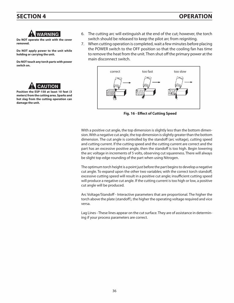
correct too slowtoo fast
Fig. 16 - effect of cutting Speed
6. The cutting arc will extinguish at the end of the cut; however, the torch switch should be released to keep the pilot arc from reigniting.
7. When cutting operation is completed, wait a few minutes before placing the POWER switch to the OFF position so that the cooling fan has time to remove the heat from the unit. Then shut off the primary power at the main disconnect switch.
With a positive cut angle, the top dimension is slightly less than the bottom dimen-sion. With a negative cut angle, the top dimension is slightly greater than the bottom dimension. The cut angle is controlled by the standoff (arc voltage), cutting speed and cutting current. If the cutting speed and the cutting current are correct and the part has an excessive positive angle, then the standoff is too high. Begin lowering the arc voltage in increments of 5 volts, observing cut squareness. There will always be slight top edge rounding of the part when using Nitrogen.
The optimum torch height is a point just before the part begins to develop a negative cut angle. To expand upon the other two variables; with the correct torch standoff, excessive cutting speed will result in a positive cut angle; insufficient cutting speed will produce a negative cut angle. If the cutting current is too high or low, a positive cut angle will be produced.
Arc Voltage/Standoff - Interactive parameters that are proportional. The higher the torch above the plate (standoff), the higher the operating voltage required and vice versa.
Lag Lines - These lines appear on the cut surface. They are of assistance in determin-ing if your process parameters are correct.
SecTION 4 OPeRaTION
37
4.4 Standoff and cut Quality
Standoff (Arc Voltage) has a direct influence on cut quality and squareness. It is recom-mended that prior to cutting, that all cutting parameters are set to the manufacturer’s suggested conditions. Refer to the Process Tables for recommendations. A sample cut should be made using actual part material followed by close examination of the part.
If the cut face of the part has excessive bevel or rounded top edge, it may be that the standoff is set too high. When standoff is controlled by an arc voltage height control, reducing the arc voltage setting will reduce the standoff.
Lower the standoff until the excessive bevel or rounded top edge disappears. The characteristics of plasma cutting hinder production of a perfectly square cut. On material thicknesses of 1/4 inch or greater, a standoff too close may result in a nega-tive cut angle.
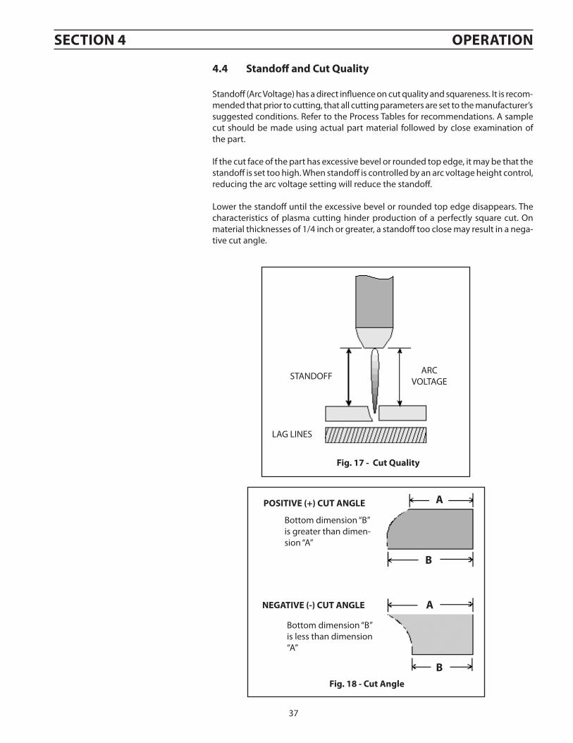
Fig. 18 - cut angle
Bottom dimension “B” is less than dimension “A”
NegaTIVe (-) cuT aNgle
Bottom dimension “B” is greater than dimen-sion “A”
POSITIVe (+) cuT aNgle a
B
a
B
Fig. 17 - cut Quality
LAG LINES
ARCVOLTAGESTANDOFF
SecTION 4 OPeRaTION
38
SuMMaRY
Arc voltage is a dependent variable. It is dependent upon cutting amperage, nozzle size, torch standoff, cut gas flow rate and cutting speed. An increase in arc voltage can result from a decrease in cutting speed, an increase in cutting amperage, a decrease in nozzle size, an increase in gas flow and an increase in torch standoff. Assuming that all of the variables are set as recommended, torch standoff becomes the most influential variable to the process. Good and accurate height control is a necessity in producing excellent cut quality.
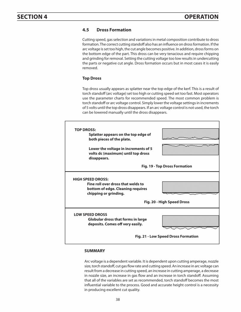
lOW SPeeD DROSS globular dross that forms in large deposits. comes off very easily.
HIgH SPeeD DROSS: Fine roll over dross that welds to bottom of edge. cleaning requires chipping or grinding.
Fig. 19 - Top Dross Formation
TOP DROSS: Splatter appears on the top edge of both pieces of the plate.
lower the voltage in increments of 5 volts dc (maximum) until top dross disappears.
Fig. 20 - High Speed Dross
Fig. 21 - low Speed Dross Formation
4.5 Dross Formation
Cutting speed, gas selection and variations in metal composition contribute to dross formation. The correct cutting standoff also has an influence on dross formation. If the arc voltage is set too high, the cut angle becomes positive. In addition, dross forms on the bottom edge of the part. This dross can be very tenacious and require chipping and grinding for removal. Setting the cutting voltage too low results in undercutting the parts or negative cut angle. Dross formation occurs but in most cases it is easily removed.
Top Dross
Top dross usually appears as splatter near the top edge of the kerf. This is a result of torch standoff (arc voltage) set too high or cutting speed set too fast. Most operators use the parameter charts for recommended speed. The most common problem is torch standoff or arc voltage control. Simply lower the voltage settings in increments of 5 volts until the top dross disappears. If an arc voltage control is not used, the torch can be lowered manually until the dross disappears.
SecTION 4 OPeRaTION
39
Tripped circuit breaker (located under the top hinged cover) may indicate dangerous high voltage existed between the work cable and earth ground. This is usually caused by a missing or poor connec-tion of the work cable to the work piece. The work cable MuST be electrically connected to the work piece to prevent dangerous shock conditions.
4.6 common cutting Problems
The following is a listing of common cutting problems and the probable cause. If problems are determined to be caused by the ESP-150, refer to the mainte-nance section of this manual. If the problem is not corrected after referring to the maintenance section, contact your ESAB representative.
a. Insufficient Penetration: 1. Cutting speed too fast 2. Damaged cutting nozzle 3. Improper gas settings 4. Inadequate delay for pierce
B. Main arc extinguishes: 1. Cutting speed too slow
c. Dross Formation: 1. Cutting speed too fast or too slow 2. Improper air pressure 3. Faulty nozzle or electrode 4. Improper standoff 5. Current too low
D. Double arcing: 1. Low air pressure 2. Damaged cutting nozzle 3. Loose cutting nozzle 4. Heavy spatter 5. Nozzle touches work while cutting 6. Pierce height too low 7. Current too low
e. uneven arc: 1. Damaged cutting nozzle or worn electrode
F. unstable cutting conditions: 1. Incorrect cutting speed 2. Loose cable or hose connections 3. Electrode and/or cutting nozzle in poor condition
g. Main arc Does Not Strike: 1. Loose connections 2. Work clamp not connected 3. Gas pressures not correct 4. Insufficient coolant to operate flow switch
H. Poor consumable life: 1. Improper gas pressure 2. Contaminated air supply 3. Improper gas/electrode combination 4. Torch hitting work piece or turned up parts 5. Parts damaged by double arcing (see D above) 6. Use of non-genuine parts 7. Water leaks in torch 8. Torch not purged after changing consumables or idle period 9. Using wrong consumables for selected gases
SecTION 4 OPeRaTION
40
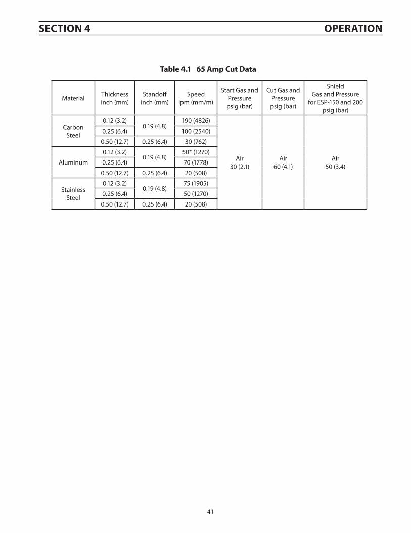
The cutting speeds and conditions in the following tables were selected to give the best quality with a particular gas combi-nation at a specific current.
Consumables - Refer to PT-26 Torch manual for recommended parts for these conditions. Use of parts in combinations and applications other than as described herein can result in damage to the torch or poor performance.
Gas and Current Selection- Refer to the following tables to choose the most appropriate conditions for your application.
SecTION 4 OPeRaTION
PT-26 in-line torch cutting conditions:
Data taken with Swirl Baffle (0558003583) and Shield Cup (0558003582).
65 Amp data uses standard Heat Shield (34592) or Close Proximity Heat Shield (37146) in place of Shield Cup (0558003582) and uses a 50 Amp Nozzle (36567).
To ensure optimum cutting performance and aid in troubleshooting any cut quality problems, please refer to the following cutting parameters charts.
Travel Speeds -Travel speeds for the PT-26 are given in Tables 4-1 through 4-4.
41
Material Thickness inch (mm)
Standoff inch (mm)
Speed ipm (mm/m)
Start Gas and Pressure psig (bar)
Cut Gas and Pressure psig (bar)
Shield Gas and Pressure
for ESP-150 and 200 psig (bar)
Carbon Steel
0.12 (3.2)0.19 (4.8)
190 (4826)
Air 30 (2.1)
Air 60 (4.1)
Air 50 (3.4)
0.25 (6.4) 100 (2540)
0.50 (12.7) 0.25 (6.4) 30 (762)
Aluminum
0.12 (3.2)0.19 (4.8)
50* (1270)
0.25 (6.4) 70 (1778)
0.50 (12.7) 0.25 (6.4) 20 (508)
Stainless Steel
0.12 (3.2)0.19 (4.8)
75 (1905)
0.25 (6.4) 50 (1270)
0.50 (12.7) 0.25 (6.4) 20 (508)
Table 4.1 65 amp cut Data
SecTION 4 OPeRaTION
42
SecTION 4 OPeRaTION
Material Thickness inch (mm)
Standoff inch (mm)
Speed ipm
(mm/m)
Start Gas and Pressure psig (bar)
Cut Gas and Pressure psig (bar)
Shield Gas and Pressure for
ESP-150 and 200 psig (bar)
Carbon Steel
0.19 (4.8)
0.19 (4.8)
150 (3810)
Air / N2 30 (2.1)
O2 60 (4.1)
Air 60 (4.1)
0.25 (6.4) 130 (3302)
0.38 (9.7) 80 (2032)
0.50 (12.7) 70 (1778)
0.62 (15.7)
0.25 (6.4)
50 (1270)
0.75 (19.1) 35 (889)
1.00 (25.4) 20 (508)
0.19 (4.8) 0.19 (4.8) 150 (3810)
Air 30 (2.1)
Air 60 (4.1)
0.25 (6.4)
0.25 (6.4)
130 (3302)
0.38 (9.7) 80 (2032)
0.50 (12.7) 70 (1778)
0.62 (15.7) 50 (1270)
0.75 (19.1) 35 (889)
1.00 (25.4) 20 (508)
Aluminum
0.19 (4.8) 0.19 (4.8) 175 (4445)
0.25 (6.4)0.25 (6.4)
130 (3302)
0.38 (9.7) 90 (2286)
0.50 (12.7)
0.31 (7.9)
70 (1778)
0.62 (15.7) 50 (1270)
0.75 (19.1) 35 (889)
1.00 (25.4) 25 (635)
Stainless Steel
0.19 (4.8) 0.19 (4.8) 165 (4191)
0.25 (6.4)0.25 (6.4)
125 (3175)
0.38 (9.7) 80 (2032)
0.50 (12.7) 0.31 (7.9) 50 (1270)
0.62 (15.7)
0.38 (9.7)
35 (889)
0.75 (19.1) 20 (508)
1.00 (25.4) 10 (254)
Table 4.2 150 amp cut Data
SecTION 4 OPeRaTION
Material Thickness inch (mm)
Standoff inch (mm)
Speed ipm
(mm/m)
Start Gas and Pressure psig (bar)
Cut Gas and Pressure psig (bar)
Shield Gas and Pres-sure for ESP-150 and 200
psig (bar)
Carbon Steel
0.25 (6.4)
0.19 (4.8)
150 (3810)
Air / N2 30 (2.1)
O2 55 (3.8)
Air 80 (5.5)
0.38 (9.7) 95 (2413)
0.50 (12.7) 80 (2032)
0.62 (15.7)
0.25 (6.4)
65 (1651)
0.75 (19.1) 50 (1270) Air 60 (4.1)1.00 (25.4) 35 (889)
0.25 (6.4) 135 (3429)
Air 30 (2.1)
Air 55 (3.8)
Air 80 (5.5)
0.38 (9.7) 95 (2413)
0.50 (12.7) 85 (2159)
0.62 (15.7) 70 (1778)
0.75 (19.1) 55 (1397)
1.00 (25.4) 30 (762)
Aluminum
0.25 (6.4) 130 (3302)
0.38 (9.7) 105 (2667)
0.50 (12.7) 85 (2159)
0.62 (15.7)0.31 (7.9)
75 (1905)
0.75 (19.1) 60 (1524)
1.00 (25.4) 0.38 (9.7) 40 (1016)
Stainless Steel
0.25 (6.4)
0.25 (6.4)
130 (3302)
0.38 (9.7) 115 (2921)
0.50 (12.7) 75 (1905)
0.62 (15.7)
0.38 (9.7)
65 (1651)
0.75 (19.1) 55 (1397)
1.00 (25.4) 20 (508)
Table 4.3 200 amp cut Data
44
Material Thickness inch (mm)
Standoff inch (mm)
Speed ipm
(mm/m)
Start Gas and Pressure psig (bar)
Cut Gas and Pressure psig (bar)
Shield Gas and Flow
cfh (l/m)
Carbon Steel
0.50 (12.7)0.25 (6.4)
130 (3302)
Air / N2 30 (2.1)
O2 75 (5.2)
Air 210 (99.1)
0.62 (15.7) 95 (2413)
0.75 (19.1)0.31 (7.9)
80 (2032)
1.00 (25.4) 50 (1270)
1.50 (38.1) 0.38 (9.7) 20 (508)
2.00 (50.8) 0.50 (12.7) 10 (254)
0.50 (12.7)
0.31 (7.9)
120 (3048)
Air 75 (5.2)
0.62 (15.7) 90 (2286)
0.75 (19.1) 80 (2032)
1.00 (25.4) 55 (1397)
1.50 (38.1) 0.38 (9.7) 25 (635)
2.00 (50.8) 0.50 (12.7) 12 (305)
Table 4.4 300 amp cut Data
SecTION 4 OPeRaTION
45
SecTION 4 OPeRaTION
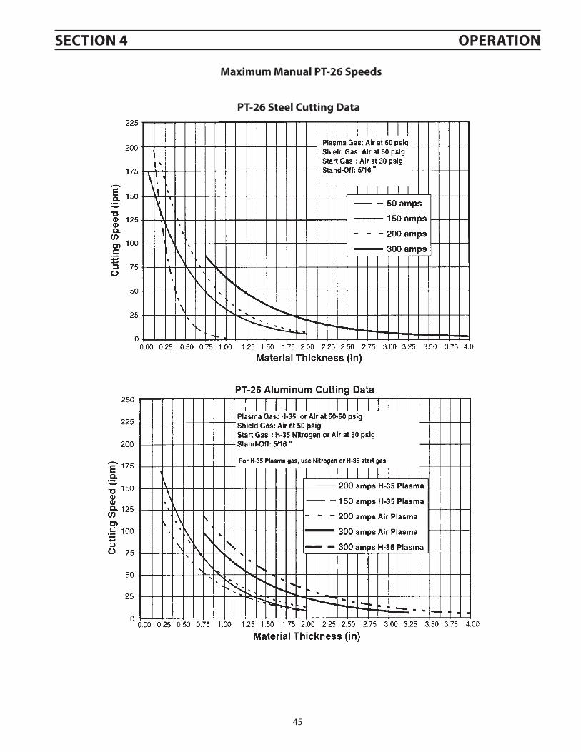
PT-26 Steel cutting Data
Maximum Manual PT-26 Speeds
46
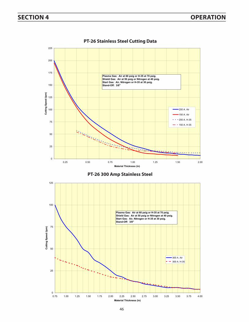
PT-26 Stainless Steel cutting Data
PT-26 300 amp Stainless Steel
0
25
50
75
100
125
150
175
200
225
0.25 0.50 0.75 1.00 1.25 1.50 2.00
Material Thickness (in)
Cut
ting
Spee
d (ip
m)
200 A. Air
150 A. Air
200 A. H-35
150 A. H-35
Plasma Gas: Air at 60 psig or H-35 at 70 psig.Shield Gas: Air at 50 psig or Nitrogen at 40 psig.Start Gas: Air, Nitrogen or H-35 at 30 psig.Stand-Off: 3/8"
Plasma Gas: Air at 60 psig or H-35 at 70 psig.Shield Gas: Air at 50 psig or Nitrogen at 40 psig.Start Gas: Air, Nitrogen or H-35 at 30 psig.Stand-Off: 3/8"
SecTION 4 OPeRaTION
47
5.0 Maintenence
If this equipment does not operate properly, stop work immediately and in-vestigate the cause of the malfunction. Maintenance work must be performed by an experienced person, and electrical work by a trained electrician. Do not permit untrained persons to inspect, clean, or repair this equipment. Use only recommended replacement parts.
a. INSPecTION aND cleaNINgFrequent inspection and cleaning of the ESP-150 cutting machine is recom-mended. Some suggestions for inspecting and cleaning are as follows: 1. Check work cable to workpiece connection.2. Check safety earth ground at workpiece and at power source chassis.3. Check heat shield on torch. It should be replaced if damaged.4. Check the torch electrode and cutting tip for wear on a daily basis. Remove
spatter, replace if necessary.5. Make sure cable and hoses are not damaged or kinked.6. Make sure all plugs, fittings, and ground connection are tight. CAUTION: Water occasionally accumulates in compressed air lines. Be
sure to direct the first blast of air away from the equipment to avoid damage.
7. With all input power disconnected, and wearing proper eye and face protection, blow out the inside of the cutting power supply using low- pressure dry compressed air.
8. Occasionally bleed water from the filter beneath the air regulators.
B. FlOW TeSTINgImproper flows can cause short life on the consumables, poor starting, bad cuts, or overheated torches. The flows given below are “cold” flow (no arc). To avoid fatal shock, follow the steps below to assure safe flow measurement.
1. Shut off input power at the main disconnect switch.2. Lift the top lid of the ESP-150 and unplug the torch switch cord.3. Close the lid.4. Turn on the power at the main disconnect switch.5. Place gas mode selector switch (OSS) in START/SHIELD position.6. Place power ON-OFF switch (ROS) to ON.7. Check flow measurements with flow measuring kit, P/N 19765.8. Place mode selector switch (OSS) in CUT position and check CUT flow
with flow measuring kit, P/N 19765.9. Place ROS switch to OFF.10. Turn off power at main disconnect switch.11. Reconnect torch switch plug inside console. PT-26 Plasma Gas Flow (No Arc): Nitrogen or Air @ 60 psig: 110 cfh; H-35 @ 90 psig: 130 cfh PT-26 Start Gas Flow: Nitrogen or Air @ 40 psig: 75 cfh PT-26 Shield Gas Flow: Air or Nitrogen @ 85 psig: 200 cfh minimum.
Be sure that all primary power to the ma-chine has been externally disconnected. Open wall disconnect switch or circuit breaker before attempting inspection or work inside of the power supply.
Voltages in plasma cutting equipment are high enough to cause serious injury or possibly death. Be particularly careful around equipment when the covers are removed.
SecTION 5 MaINTeNaNce
The coolant must be handled as chemical waste.cauTION
48
Be sure that all primary power to the ma-chine has been externally disconnected. Open wall disconnect switch or circuit breaker before attempting inspection or work inside of the power supply.
Voltages in plasma cutting equipment are high enough to cause serious injury or possibly death. Be particularly careful around equipment when the covers are removed.
Voltages in plasma cutting equipment are high enough to cause serious injury or possibly death. Be particularly careful around equipment when the covers are removed.
c. SPaRK gaP aDJuSTMeNTThe spark gap, which is part of the high frequency generator, is factory set at 0.040-in. (+/- 0.002). After extended operation or if erratic operation is noted, it may be neces-sary to readjust or replace the electrodes. Use a feeler gauge when readjusting the gap. Cleaning or dressing of the spark gap electrodes is not recommended. When replacement is necessary, both electrodes should be replaced.
D. TeSTINg aND RePlacINg BRIDge aSSeMBlY cOMPONeNTSThe silicon diodes and SCR’s used in the power supply are devices which allow current to flow in only one direction. They block current in the other direction. The diodes and SCR’s are designed to provide long troublefree operation; however, should a failure occur, they may require replacement.
1. Testing Diodes a. Locate the main rectifier assembly containing the silicon diodes and
SCR’s. b. Electrically isolate main bridge rectifier assembly by disconnecting
the main transformer secondary fuse links F1 and F2. c. With ohmmeter on RX1 scale, place negative lead on the diode heat
sink and touch positive lead to each pigtail terminal. Meter should read a low resistance of approximately 3 to 15 ohms on each diode.
d. Reverse leads and check each diode. All readings should show high resistance of 2 K (2000) ohms or higher. With most ohmmeters on the RX1 scale, 2K ohms is the highest possible reading available.
e. Since diode resistance is non-linear with voltage (using any scale), diodes are good when they show low resistance in one direction and high resistance in the opposite direction. They are bad when they show no or very low resistance in both directions (shorted), or if they show very high assistance in both directions (open).
2. Testing SCR’s a. Follow steps a. and b. under Testing Diodes. Disconnect the SCR pig-
tail. b. With ohmmeter on RX1 scale place the negative lead on the anode
(end of SCR with screw threads) and positive lead on the cathode (pigtail end). Meter should read a high resistance of 2 K (2000) ohms or higher.
c. Reverse leads and check each SCR. All readings again should show high resistance. When SCR’s are bad they show low resistance in either direction.
d. Now check the gate circuit on the SCR’s by placing the negative lead to the gate (wht wire off SCR) and the positive lead to the cathode. Meter should read approximately 20 ohms and should vary only slightly (5 ohms) when leads are reversed. If the meter reads zero or infinity in either direction the gate circuit is faulty and the SCR should be replaced.
IMPORTANT: When replacing Diodes or SCR’s make sure mounting surfaces are clean. Coat mounting surfaces with Alcoa No. 2 EJC Electri-cal Joint Compound (no substitutes) available in 8 oz. bottles under P/N 73585980. Use a torque wrench to tighten diodes and SCR’s. Recommended torques are 20-30 in.-lbs. for diodes; 125-150 in.-lbs. for SCR’s.
SecTION 5 MaINTeNaNce
49
5.1 Troubleshooting
Check the problem against the symptoms in the following troubleshooting guide. If the cause cannot be quickly located, shut off the input power, open up the unit, and perform a simple visual inspection of all the components and wiring. Check for components, bulged or leaking capacitors, or any other sign of damage or discoloration.
The cause of control malfunctions can also be found by referring to the sequence of operations and electrical schematic diagram and check out the various components. A volt-ohmmeter will be necessary for some of these checks.
Be sure unit is set up properly for voltage being used and that the gas supplies are adequate.
a. TROuBleSHOOTINg guIDe
1. unit Inoperative; fan does not run. a. Check primary disconnect switch to make sure input power is being supplied. b. Check links on the input terminal board TB to make sure all are connected to the proper input voltage
being used. (See Form 14-376.) c. Check for defective power switch (ROS).2. No gas flow when torch switch is closed. a. Unplug torch switch plug and check for proper operation with an ohmmeter connected to pins 1 and 2 of
torch switch plug. b. Defective interlock switch (ISW). c. Check for defective solenoid valves. d. Plug (P1) may be loose at control board. e. Defective logic board.3. Pilot arc-high frequency sparks noted at spark gap but not at the torch. a. Check spark gap and readjust electrodes if necessary. Replace spark gap electrodes if worn beyond service-
ability. b. Check with an ohmmeter for continuity between torch nozzle and POS output where torch attaches to
console.4. No pilot arc-high frequency sparks noted at spark gap and at torch during preflow, but main contactor
does not activate or chatters at end of 2 second preflow time. a. Check start gas pressure. It must be at least 30 psig. b. Check cooling gas pressure (PT-26). It must be at least 50 psig. c. If using PT-26 torch, check jumper plug between J1-5 and J1-4 on the torch switchplug. d. Thermal switch in bridge, inductor, or main transformer may be open. Allow unit to cool down. e. Defective logic board (675369).5. No pilot arc - No spark noted in the spark gap. a. Check to see that pilot arc contactor (PAC) closes. If it does not, and gas flows when torch switch is closed,
replace logic board. b. If PAC closes, check for proper spark gap setting (0.040-in.). c. Check the 120V input to the high voltage transformer (HFTR). d. Check for arcing or carbon tracking around the spark gap. e. If all of the above check good, HFTR is most likely defective. 6. erratic pilot arc - pilot arc contactor (Pac) chatters. a. Defective logic board. b. Power supply may be single phasing. Check main disconnect switch and fuses.
SecTION 5 MaINTeNaNce
50
7. No pilot arc - pilot arc contactor (Pac) drops out when main contactor (Mc) activates at end of 2-second preflow.
a. Check for low open circuit voltage. It should be around 370 V at nominal line voltage. b. Check voltage between each side of resistor R29 and the WORK output connection when MC is activated.
Place negative meter lead on side of resistor being checked and positive meter lead on the WORK output connection. The voltage on one side should be the open circuit voltage (370 V). The voltage on other side should be above 175 V. If lower voltage is under 175 V, PAC will drop out.
c. Check the resistance of R29. It should be 133 K ohm. d. Disconnect R-29 resistor and measure the resistance from P1-1 to shunt (common). Resistance should be
200 K to 250 K ohms. e. Check for continuity between R29 and electrode (-) torch connections. f. With power off, mechanically pull in PAC. The resistance between POS and WORK connections should be
8 ohms.8. Main arc fails to transfer to work. a. Make sure that work clamp is securely fastened to the work piece. b. Check for proper function of pilot arc (PT-26) and high frequency unit. c. Check main disconnect switch and fuses. d. Check main contactor (MC) by disconnecting primary power and check each contact for closure using an
ohmmeter while physically pulling contactor. e. Check C24 and C24A capacitors (1900 uf, 450 V) with an ohmmeter. Resistance should be 900-1000 ohms
with capacitor connected in the circuit. If shorted, replace capacitor. Then check R18 resistor. The resistance of R18 should be 5 ohms. The resistance between “DRB POS” and “CAP (+)” should be 25 ohms. If the stud mounted rectifier on D/R board is shorted, the 25 ohm will be less than 5 ohms even when meter probes are reversed.
f. Check open circuit voltage. It should be about 370 volts. g. Check F1 and F2 fuses. The open circuit can still be 370 volts with one blown fuse. h. Current control board (674935) may be defective.9. Short tip life. a. Check for correct gas pressure. b. Check gas flow rate using flowmeter (P/N 19765). c. Check to see if pilot arc contactor (PAC) remains activated after main arc transfers. This can be done by
observing the spark in the spark gap of the high freq. unit. The high freq. spark should shut off as soon as main arc starts. If spark continues after main arc is established, either main contactor (MC) or logic board is defective.
d. Arc current is set too high. e. Wrong cutting tip size. Use larger tip. f. Defective current control board.10. Pilot arc cycles on and off when torch switch is not depressed. a. Unplug torch switch plug. If cycling stops, then torch switch wires or plug or torch switch itself are short-
ed. b. Defective logic board.11. No or limited control of output current. a. Defective current control potentiometer (CCP). Check by placing negative meter lead on WORK output
connection and positive meter lead on current control board P1-2. (P1 is the larger of the two plugs.) With the fan running (machine at idle), adjust CCP from min. to max. They read zero at min. (1.1 volts on ESP-150); 10 Volts DC at max. The meter should move smoothly from zero to 10 V as CCP is rotated from min. to max.
b. Defective logic board.12. gas does not shut off after 10 seconds of preflow. a. Turn off ready-off switch (ROS). If gas continues to flow, solenoid valve is defective. b. Defective logic board.13. No arc.Check that the mains power supply switch isturned on.Check that the welding current supply andreturn cables are correctly connected.Check that the correct current value is set.14. The welding current is interrupted during welding.Check whether the thermal overload tripshave operated (indicated by the lamp on thefront panel).Check the mains power supply fuses.
SecTION 5 MaINTeNaNce
51
15. The thermal cut-out trips frequently.Make sure that you are not exceeding therated data for the power source (i.e. that theunit is not being over-loaded).16. Poor welding performance.Check that the welding current supply andreturn cables are correctly connected.Check that the correct current value is set.Check that the correct electrode is beingused.Check the mains power supply fuses.
B. SeQueNce OF OPeRaTION
1. Close primary disconnect switch. a. Power supplied to unit.2. Place Power Switch (ROS) to “Ready” position. a. Fan motor (FM) and Pump motor on. b. Low Gas LED on. c. Control circuit energizes.3. Place Gas Mode Switch (OSS) to “CUT” position. a. Gas solenoid valves (CGSV) energize. Gases flow to permit setting of pressures and to purge system.4. Place OSS to “Operate” position. a. Gas valves (PGSV and CGSV) deenergize to stop gas flows.5. Depress torch switch. a. SHSV and SGSV (shield and start) gas solenoid valves open to allow gases to flow to torch. b. Pilot Arc Contactor (PAC) closes. c. High Frequency (HF) energizes. d. Pressure Switches (PGPS & CGPS) close (provided gas pressures are set above 19 psig on PGPS and 22 psig
on CGPS). e. Two seconds later, Main Contactor (MC) closes to establish pilot arc. f. Pilot arc will transfer to cutting arc within 6 seconds as long as torch is close enough (1/8” —1/4”) to
work. g. HF and PAC deenergizes immediately when cutting arc is established, or after 6 seconds of continuous
pilot arc. If cutting arc is not established after six seconds, MC will open but the HF will remain energized. MC and pilot arc will then cycle on and off every 3 seconds, MC will open but the HF will remain energized. MC and pilot arc will then cycle on and off every 3 seconds until torch switch is released.
* HF and Mc remain on for approximately 6 sec. unless a main arc is established. If a main arc is not established the Mc will open after 6 sec. but HF stays on. If torch switch is not released Mc will cycle on and off every 3 sec. until torch switch is released.
** cutting arc actually starts during the HF phase when the arc transfers to the workpiece anywhere between 2 and 6 seconds; Pilot arc circuit and high-freq. generator will then shut off immediately.
*** a new cycle may be started anytime in the Postflow phase, which will cancel remaining postflow time and start again with the normal preflow time.
**** On units made for advance Systems cutting machines, HF activates when Mc closes at end of 2 second preflow.
Fig. 22 - Torch Operation Sequence Diagram
SecTION 5 MaINTeNaNce
WaRNINgDaNgeROuS HIgH VOlTage (OVeR 300 VOlTS) exISTS aT THe TORcH FRONT eND WHeNeVeR Mc IS clOSeD; THeReFORe, ReleaSe TORcH SWITcH WHeN cuTTINg IS NOT eSTaBlISHeD aND RePeaT STeP 5.
52
6. Release torch switch. a. MC opens and the cutting arc shuts off. b. Gases continue to flow (postflow) for approximately another 10 seconds at which time the PGSV and CGSV
7. Control circuit will not energize or can deenergize during a cutting cycle when: a. PGPS or CGPS is open due to insufficient gas pressure (at least 15 psi required). b. Thermal Switches (TS) are open due to overheating of unit. TS should open at 180° C (356° F).8. Place ROS to “OFF” position. a. Control circuit deenergizes. b. Fan motor (FM) deenergizes. c. Low Gas light on status board will go out.9. Open primary disconnect switch. a. Input power unit shut off.
SecTION 5 MaINTeNaNce
53
Proper InputPower Applied
ROS ON
IsOVER TEMP
LightOn?
1. Machine may be overheated.2. Check connections to thermal switches (TS).
IsREADY/LOW GAS
LightOn?
1. Close top lid.2. Check ISW switch3. Check CB1.
Set Gas(es) at proper pressure with OSS switch in CUT/START-SHIELDmode.
Place OSS switch in OPERATE
Depress TorchSwitch
Is HIGH FREQ
LightOn?
DoesLOW GASLight GO
Off?
1. Check input gas pressure.2. Check gas flow of PT-26. Check to be
sure consumables are good and prop-erly in place.
3. Check torch switch for intermittent con-nection.
4. If using PT-26, check jumper between pin 4 and 5.
1. Check OSS switch.2. Check Torch Switch.3. Check PAC contactor to insure 24 VAC is
applied to coil.4. Check PC Board.5. Check HFTR Transformer
2 second delay
Unit in Post Flow mode and ready to cut again.
LOW GAS lightturns on
Release torch switch
Adjust cutting speed
HIGH FREQ lightgoes out
Is Main Arc
established?
1. Check work lead connection.2. Check consumables in torch.3. Check for proper nozzle and
current. At low currents, the arc length has to be closer to work.
4. Check all input voltages between lines.
5. Check open circuit voltage.6. Check diodes and SCR’s.7. Check PC board.
Touch pilot arc to work piece within 6 sec. after pilot arc is established, or pilot arc will turn off and begin cycling on and off about every 3 sec.
1. Check consumables in torch.2. Check torch connections using
ohmmeter.3. Check open circuit voltage (325
VDC). (Disconnect HF to avoid damaging meter.)
4. Check HF at spark gaps. (ISW switch must be closed when performing check.) May have to reset spark gap.
5. Check PAC contactor.6. Check R20 and R21 resistors.
1. Check open circuit voltage. Should be about 370 VDC. (Dis-connect HF to avoid damaging meter.)
2. Check input power.3. Check MC contactor.4. Check diodes and SCR’s.5. Check PC board.
Is Pilot Arc
established?
DoesTORCH ONLight turn
on?
“A”
“A”
YES
NO
c. STaTuS lIgHT TROuBleSHOOTINg cHaRT
NO
YES
YES
NO
NO
YES
YES
NO
NO
YES
YES
NO
SecTION 5 MaINTeNaNce
54
SecTION 5 MaINTeNaNce
55
SecTION 6 RePlaceMeNT PaRTS
6.1 general
Always provide the serial number of the unit on which the parts will be used. The serial number is stamped on the unit nameplate.
To ensure proper operation, it is recommended that only genuine ESAB parts and products be used with this equipment. The use of non-ESAB parts may void your warranty.
Replacement parts may be ordered from your ESAB Distributor.
Be sure to indicate any special shipping instructions when ordering replacement parts.
Refer to the Communications Guide located on the back page of this manual for a list of customer service phone numbers.
6.2 Ordering
6.0 Replacement Parts
XBill of Material item numbers enclosed by a square denote sub-assemblies.Refer to Bill of Material to identify items that make up the sub-assembly.Sub-assemblies may be ordered instead of ordering each item individually.
NOTe:
The ESP-150 is designed and tested in accordance with the international and European standards EN 60974-1 and EN 60974-10. It is the obligation of the service unit which has carried out the service or repair work to make sure that the product still conforms to the said standard. Repair and electrical work should be performed by an authorized ESAB serviceman. Use only ESAB original spare and wear parts. Spare parts may be ordered through your nearest ESAB dealer, see the last page of this publication.
NoteSchematics and Wiring Diagrams are printed on
279.4mm x 431.8mm (11” x 17”) paper and are included inside the back cover of this manual.
56
SecTION 6 RePlaceMeNT PaRTS
9
8
18
19
4
1
5
20
3
17
11
10
7
2 16 13 6
14
15
12
57
SecTION 6 RePlaceMeNT PaRTS
ITeM QTY PaRT NO DeScRIPTION SYMBOl1 1 0558002680M PANEL FRONT2 1 0558002683Y PANEL TOP3 1 0558002681Y PANEL SIDE LEFT4 1 0558002682Y PANEL SIDE RIGHT5 1 0558002678M PANEL BASE
6 1 0558002806 CONTROL PANEL TOP ASSY (Includes Items 7 thru 10)
7 1 680718 CONTROL PANEL TOP SHELL8 1 0558003773 PANEL CONTROL SILKSCREENED9 1 0558003775 PC BOARD - STATUS LIGHTS SLBD
ITeM QTY PaRT NO DeScRIPTION SYMBOl131 1 0558004065 TANK COOLANT 6 QUART132 1 0558004064 SWITCH FLOW 0.25GPM133 1 10Z30 ADAPTOR RH B/A-W*M 1/4NPTM134 1 58V75 ADAPTOR BULKHEAD LH B/A-W*F 1/4NPTM135 1 0558004062 PUMP COOLANT 60PSI 96GPH136 2 0558006272 ADAPTOR BUSHING 1/4NPTF 3/8NPTM137 2 67101075 NIPPLE 1/4NPT138 1 461107 TEE STREET 1/4NPT139 1 598481 GAGE PRESSURE 200PSI 1400KPa140 1 21124 CHECK VALVE141 2 10Z30 ADAPTOR RH B/A-W*M 1/4NPTM142 1 0558004063 MOTOR COOLANT PUMP 1/3 HP PM143 1 0558002685M BRACKET MOUNTING COOLANT PUMP MOTOR144 1 0558002901 BLADE COOLANT PUMP MOTOR 9.75”145 3 0558004070 RESISTOR 470 OHM 2W R51,52,53146 1 0558002687M PANEL SIDE AIR EXIT CHAMBER147 1 0558002807M BAFFLE RIGHT
70
SecTION 6 RePlaceMeNT PaRTS
71
NOTeS
72
NOTeS
73
1. Revision “C” - 07/2004 - Revised with updated schematic diagrams. Made various editorial changes also.2. Revision “C” - 08/2006 - Replacement parts section, front view, changed item 11 from: p/n 950812 to: 636702.3. Revision “D” - 02/2007 - updated / replaced Replacement Parts section.4. Revision “E” - 06/2008 - updated P45 / J5 location functions in Section 3.5. Revision “F” - 06/2010 - updated Replacement Parts section with VDR board and bracket info & updated schem
pack. Added VDR adjustment info in INSTALLATION section.6. Revision “F” - 11/2010 - Updated schematic pack per DNECO # 103119.7. Revision “F” - 08/2012 - Updated contactor BOM p/n’s for J. Magee.8. Revision “F” - 08/2014 - Removed “7” prefix from BOM item 50.9. Revision “H” - 02/2015 - Updated cut data section.
ReVISION HISTORY
A. CUSTOMER SERVICE QUESTIONS: Telephone: (800)362-7080 / Fax: (800) 634-7548 Hours: 8:00 AM to 7:00 PM EST Order Entry Product Availability Pricing Order Information Returns
B. ENGINEERING SERVICE: Telephone: (843) 664-4416 / Fax : (800) 446-5693 Hours: 7:30 AM to 5:00 PM EST Warranty Returns Authorized Repair Stations Welding Equipment Troubleshooting
C. TECHNICAL SERVICE: Telephone: (800) ESAB-123/ Fax: (843) 664-4452 Hours: 8:00 AM to 5:00 PM EST Part Numbers Technical Applications Specifications Equipment Recommendations
D. LITERATURE REQUESTS: Telephone: (843) 664-5562 / Fax: (843) 664-5548 Hours: 7:30 AM to 4:00 PM EST
E. WELDING EQUIPMENT REPAIRS: Telephone: (843) 664-4487 / Fax: (843) 664-5557 Hours: 7:30 AM to 3:30 PM EST Repair Estimates Repair Status
F. WELDING EQUIPMENT TRAINING Telephone: (843)664-4428 / Fax: (843) 679-5864 Hours: 7:30 AM to 4:00 PM EST Training School Information and Registrations
G. WELDING PROCESS ASSISTANCE: Telephone: (800) ESAB-123 Hours: 7:30 AM to 4:00 PM EST
H. TECHNICAL ASST. CONSUMABLES: Telephone : (800) 933-7070 Hours: 7:30 AM to 5:00 PM EST
IF YOu DO NOT KNOW WHOM TO call
Telephone: (800) ESAB-123 Fax: (843) 664-4462
Hours: 7:30 AM to 5:00 PM ESTor
visit us on the web at http://www.esabna.comThe ESAB web site offers
Comprehensive Product InformationMaterial Safety Data Sheets
Warranty RegistrationInstruction Literature Download Library