ORNL is managed by UT-Battelle for the US Department of Energy Plasma processing for SNS cryomodules Presented to the WG-2 at TTC meeting MSU Sang-ho Kim on behalf of SCL Systems group SNS, ORNL April 23, 2017
Transcript
ORNL is managed by UT-Battelle for the US Department of Energy
Plasma processing for SNS cryomodules
Presented to the WG-2 at TTC meeting MSU Sang-ho Kim on behalf of SCL Systems group SNS, ORNL
April 23, 2017
2 TTC Feb. 2017 S-H. Kim
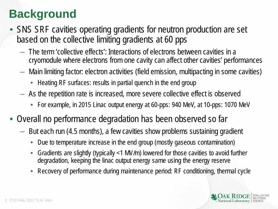
Background • SNS SRF cavities operating gradients for neutron production are set
based on the collective limiting gradients at 60 pps – The term ‘collective effects’: Interactions of electrons between cavities in a
cryomodule where electrons from one cavity can affect other cavities’ performances – Main limiting factor: electron activities (field emission, multipacting in some cavities)
• Heating RF surfaces: results in partial quench in the end group – As the repetition rate is increased, more severe collective effect is observed
• For example, in 2015 Linac output energy at 60-pps: 940 MeV, at 10-pps: 1070 MeV
• Overall no performance degradation has been observed so far – But each run (4.5 months), a few cavities show problems sustaining gradient
• Due to temperature increase in the end group (mostly gaseous contamination) • Gradients are slightly (typically <1 MV/m) lowered for those cavities to avoid further
degradation, keeping the linac output energy same using the energy reserve • Recovery of performance during maintenance period: RF conditioning, thermal cycle
3 TTC Feb. 2017 S-H. Kim
Motivation • To achieve 1-GeV operation, we need to IMPROVE the cavity performance to a
new higher operating gradients – Especially for high beta cavities: show more collective effects since electron acceleration is
more efficient • Preliminary test and analysis
– Plasma processing will give the best chance for improving SNS cavity performance in a cost effective manner
– Hydrocarbons are observed: • on all Nb samples tested at SNS, • from SNS cryomodule surfaces during thermal cycle, • from the first attempt of plasma in a SNS cryomodule in 2009
SIMS on sample
During CM warm-up H2
CH4 C2H4
4 TTC Feb. 2017 S-H. Kim
Hydrocarbons tends to lower work function of Nb surface
• Plasma processing at SNS aims at – Reducing FE by increasing work function of cavity RF surface – Enabling operation at higher accelerating gradients
• Scaling from Fowler-Nordheim equation
– 10-20% increase in φ leads to 20-30% increase in Eacc
• Work function measurement with samples using Kelvin probe • Goal: improve high beta cavity performance by 15% on average
( ) 2/1
2/32
φβφ
φβ
cE
beEaJ
+−
=
φφd
EdEdJ
acc
acc
230 ≈⇒=
J : current density E : surface electric field β : field enhancement factor φ : work function
5 TTC Feb. 2017 S-H. Kim
Plasma processing R&D approach at SNS
R&D with Nb samples and offline cavities
In-situ processing in linac tunnel Processing of cryomodule in test cave
1st phase 2nd phase
4th phase 3rd phase
Processing of 6-cell cavity in HTA*
On-going FY16 FY17
*HTA: Horizontal Test Apparatus
HB49 HB52
CM00012 CM00023 CM00022
6 TTC Feb. 2017 S-H. Kim
R&D focus for in-situ plasma processing at SNS • Stable and reliable ignition of plasma in a desired cell
– Critical for in-situ plasma processing • No visual monitoring is available for cryomodules in the
tunnel • Coupler could be damaged if ignition happens around
coupler – Ignition and monitoring technique based on developed
model at SNS: Works nicely! • Process gas optimization
– Ne (background) for stability of plasma and O2 as a reactive gas
• Monitoring plasma processing – Hydrocarbons removed from top surface through
oxidation and formation of volatile by-products (H2, H2O, CO, CO2)
• Process duration and number of process cycles • Procedure and hardware for in-situ processing in the
tunnel: developed and implemented
M. Doleans, "Ignition and monitoring technique for plasma processing of multicell superconducting radio-frequency cavities." Journal of Applied Physics 120(24), 243301 (December 2016) http://dx.doi.org/10.1063/1.4972838
Radiation Level reduced after plasma processing • Examples of radiation signals from two cavities • Plasma processing has been observed to reduce radiation related to both
field emission and multipacting • Reduction varies between cavities
6 8 10 12 14 16
10-6
10-5
10-4
before plasma processing after plasma processing
radi
atio
n (ra
d/pu
lse)
Eacc (MV/m)
CM00012 - cavity A
8 10 12 14 16
10-6
10-5
10-4
before plasma processing after plasma processing
radi
atio
n (ra
d/pu
lse)
Eacc (MV/m)
CM00012 - cavity B
Field emission regime Multipacting regime
9 TTC Feb. 2017 S-H. Kim
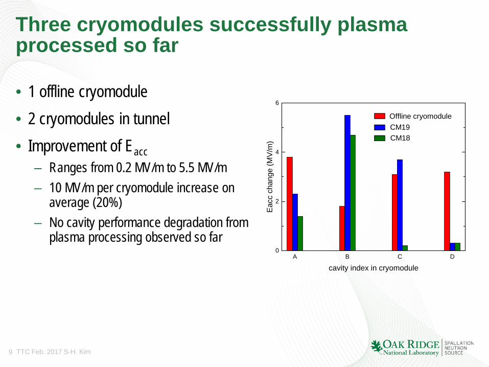
Three cryomodules successfully plasma processed so far
• 1 offline cryomodule • 2 cryomodules in tunnel • Improvement of Eacc
– Ranges from 0.2 MV/m to 5.5 MV/m – 10 MV/m per cryomodule increase on
average (20%) – No cavity performance degradation from
plasma processing observed so far
A B C D0
2
4
6
Eacc
cha
nge
(MV/
m)
cavity index in cryomodule
Offline cryomodule CM19 CM18
10 TTC Feb. 2017 S-H. Kim
Linac output energy has been increase to 972 MeV since July 2016 (highest ever for 60-Hz operation) • Changes of output energies are the result from specific activities and events • Current plan to achieve a stable 1-GeV operation is;
– During upcoming summer outage, deploy plasma processing technique to two additional cryomodules (CM16 and CM17) – During the following winter outage, deploy the technique to two or three additional cryomodules (CM21, CM22 and CM23)
Additional HVCM
Recognized Errant Beam
RF/Control improvement Two CM Repairs Other misc.
1. Full pulse length for 1.4 MW
3 cavities Turned off
(errant beam)
CMs out from slot 6 and 20
for repair
High beta spare CM in for slot 20
MB CM in (slot 6) after repair
2. Worst performing HB CM out (slot 19), HB CM from slot 20 in after repair
First in-situ plasma processing & recoveries
Second in-situ plasma
Processing &
recoveries
plasma processing for 5 CMs
1 2
Lina
c ou
tput
ene
rgy
(MeV
)
1 GeV
940 MeV 957 MeV
972 MeV
11 TTC Feb. 2017 S-H. Kim
Summary
• Plasma processing technique developed at SNS cleans surface hydrocarbons and increase work function – Reduces field emission – Also helps removing adsorbed gases and reduce SEY
• Recipe, hardware and procedure are developed and the technique is successfully deployed to three cryomodules
• Near term goal is to reach 1 GeV operation at 60 Hz • Plasma processing for SNS medium beta cavity is under development for
the SNS Proton Power Upgrade (PPU) project – Take advantage of RF budget available in medium beta section
12 TTC Feb. 2017 S-H. Kim
Backup slides
13 TTC Feb. 2017 S-H. Kim
Radiation waveforms from field emission and multipacting
Cavity field in open loop Cavity field in open loop
Field emission Multipacting
Time (µs)
Rad
iatio
n (a
rb. U
nit)
Rad
iatio
n (a
rb. U
nit)
Time (µs)
14 TTC Feb. 2017 S-H. Kim
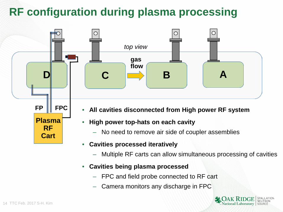
RF configuration during plasma processing
C
• All cavities disconnected from High power RF system
• High power top-hats on each cavity – No need to remove air side of coupler assemblies
• Cavities processed iteratively – Multiple RF carts can allow simultaneous processing of cavities
• Cavities being plasma processed – FPC and field probe connected to RF cart – Camera monitors any discharge in FPC
A B gas flow
D
FP
Plasma RF
Cart
top view
FPC
15 TTC Feb. 2017 S-H. Kim
Plasma processing in SNS linac tunnel
CM plasma processed
CM CM WS WS WS
cold warm warm
CM: Cryomodule WS: Warm Section BL: Beamline turbo cart RGA: Turbo cart with RGA GAS: Plasma gas manifold cart IP: Ion pump CCG: Cold cathode gauge SGV: Sector gate valve
IP off
CCG off
IP off
gas in
gas out
BL CM
RGA WS
BL WS
BL CM
BL WS
GAS CM
SGV
• Warm-up 2 cryomodules
• Sections seeing process gas during processing – Ion pumps and CCGs off
• Adjacent sections not seeing process gas – Close sector gate valves to protect nearest cold cryomodules