PLASMA PROCESSING UPDATE A newsletter from the Facilitation Centre for Industrial Plasma Technologies, Institute for Plasma Research Issue 53 Jan – April 2008 Contents ♦ Editor's Note ♦ About FCIPT -Facilitation Centre for Industrial Plasma Technologies ♦Research at FCIPT - Energy Recovery from Plasma Pyrolysis of waste ♦ Plasma Based Processes - Spacecraft/Solar-panel Plasma Interaction Experiments (SPIX) - Interface studies of carbon-copper alloy joints for tokamak applications ♦ Equipment Delivery - Plasma Nitriding System installed at BIT, Jaipur - Angora System Installed at Kullu - Plasma Pyrolysis system installed at Hyderabad
Transcript
PLASMA PROCESSING UPDATE
A newsletter from the Facilitation Centre for Industrial Plasma Technologies,
Institute for Plasma Research Issue 53 Jan – April 2008
Contents
♦♦♦♦ Editor's Note
♦♦♦♦ About FCIPT -Facilitation Centre for Industrial Plasma
Technologies ♦♦♦♦Research at FCIPT - Energy Recovery from Plasma Pyrolysis of waste ♦ Plasma Based Processes - Spacecraft/Solar-panel Plasma Interaction Experiments (SPIX) - Interface studies of carbon-copper alloy joints for tokamak applications ♦♦♦♦ Equipment Delivery - Plasma Nitriding System installed at BIT, Jaipur - Angora System Installed at Kullu - Plasma Pyrolysis system installed at Hyderabad
Editor's note Disposal of medical and plastic waste presents problems on one hand and valuable potential as energy on the other hand. To alleviate part of our energy crisis and environmental degradation, it has become imperative to make use of appropriate technologies for recovery of energy resources from waste. Dr. S. K. Nema with his team at FCIPT has successfully demonstrated the energy recovery from plasma pyrolysis of plastic and cotton waste. Design of spacecraft for long duration mission presents new challenges due to the possible spacecraft systems interaction with the environment. In order to understand the interaction of space plasma with solar array, experimental and theoretical/numerical modelling studies have been initiated at FCIPT, under ‘Solar panel Plasma Interaction eXperiment’ (SPIX) program. Ms. Bhoomi Mehta describes the various causes that lead to the degradation of solar arrays by performing various experiments in the test facility built at FCIPT. Tungsten and Carbon based materials are the most promising candidates for plasma facing materials used in fusion reactor. The plasma-facing components are subjected to stationary heat fluxes of 10-20 MW/m². Precipitation hardened CuCrZr is used as heat sink material to transfer the heat from the plasma-facing protection material to the water coolant. Dr. Raole and his team in FCIPT investigated the joints between carbon based materials to copper based heat sink by using several characterization instruments. Editor : Alphonsa Joseph Co-editor : A. Satyaprasad
Conference Presentations from FCIPT Name of the Author
Topic Date Place Conference
Dr. S. Mukherjee
Plasma Source Ion Implantation and its Application
March 31st - 4th
April, 2008
Institute for Physics, Bhubaneshwar
Material Characterization and Surface Modification in Research and Industry using Ion Accelerators. MCIA-2008
Dr. S. K. Nema
Atmospheric Pressure Plasma and its Application
10 - 11th April 2008
Institute for Plasma Research, Gujarat
DST-PSSI Interaction Meet
Dr. S. Mukherjee
Popularizing Plasma Science, Technology and its Applications in Indian Academic Organizations
10 - 11th April 2008
Institute for Plasma Research, Gujarat
DST-PSSI Interaction Meet
About FCIPT
Facilitation Centre for Industrial Plasma Technologies The Institute for Plasma Research (IPR) is exclusively devoted to research in plasma science, technology and applications. It has a broad charter to carry out experimental and theoretical research in plasma sciences with emphasis on the physics of magnetically confined plasmas and certain aspects of nonlinear phenomena. The institute also has a mandate to stimulate plasma research activities in the universities and to develop plasma-based technologies for the industries. It also contributes to the training of plasma physicists and technologists in the country. The Institute has recently embarked on an ambitious project of building a Steady State Superconducting (SST-1) Tokomak. IPR has been declared as the domestic agency responsible in INDIA to design, build and deliver advanced systems to ITER (International Thermonuclear Experimental Reactor), to develop nuclear fusion as a viable long-term energy option. The Facilitation Centre for Industrial Plasma Technologies (FCIPT) links the Institute with the Indian industries and commercially exploits the IPR’s knowledgebase. FCIPT interacts closely with entrepreneurs through the phases of development, incubation, demonstration and delivery of technologies. Complete package of a broad spectrum of plasma-based industrial technologies and facilitation services is offered. Some of the notable achievements of FCIPT are: plasma nitriding of industrial components to increase wear resistance and hardness, coating of quartz-like films on brassware to inhibit oxidation and tarnishing, thermal plasma technologies for waste treatment, plasma processing for textile industries, deposition of TiN coatings to increase abrasion resistance, deposition of amorphous silicon coatings for anti-reflection properties, etc. The Centre has process development laboratories, jobshops and material characterisation facilities like Scanning Electron Microscope, X-ray Diffractometer, Microhardness testing facilities, which are open to users from industry, research establishments and universities. This newsletter is designed to help you keep abreast with the developments in the important field of plasma assisted manufacturing and to look for new industrial opportunities. We would be very happy to have you write to us on ways of improving this service or visit us for further discussions. Please visit our website: http://www.plasmaindia.com or http://www.ipr.res.in/fcipt
Research at FCIPT Energy recovery from Plasma Pyrolysis of Waste Dr. S.K. Nema is an expert in PECVD, Plasma Polymerization, and Plasma Pyrolysis
Safe disposal of medical waste along with energy recovery options makes the plasma pyrolysis technology very attractive. FCIPT, Institute for Plasma Research, has developed the plasma pyrolysis technology to destroy medical waste, and has successfully demonstrated it at Gujarat Cancer Research Institute (GCRI), Ahmedabad. The objective of the plasma pyrolysis process is clean disposal of medical and other wastes. However it was realized, later that, energy stored in the waste itself can be recovered during the pyrolysis process. In a sponsored project from CFEES (DRDO, Delhi), FCIPT explored the possibility of energy recovery during pyrolysis of plastic and cotton waste and understood its effect on the economics of the pyrolysis technology. Plasma pyrolysis is a destructive decomposition process. In this process the waste is exposed to high temperatures in an oxygen starved environment. High temperature is produced by a plasma torch which converts electrical energy into heat energy. The pyrolysis results in main chain scission and generation of free radicals which efficiently break C-C bonds and C-H bonds present in plastic and cotton molecules. As a result, gaseous products like light hydrocarbons, aromatics, hydrogen and carbon monoxide, and considerable amount of soot are formed. The efficiency of production and concentration of the above mentioned products depend primarily on the temperature of the pyrolysis process. A plasma pyrolyser of 15 kg/hr capacity has been used to carry out the initial experiments to generate data on energy recovery process. In a typical plasma pyrolysis system the waste is initially pyrolysed in the primary chamber where it is converted to gaseous products. These gaseous products are then combusted in the secondary chamber and finally released into the atmosphere after cleaning them in the scrubbers. However in the energy recovery system, as the prime aim is to collect the combustible gases, secondary chamber is not necessary. The primary chamber is directly connected with a scrubbing unit. This scrubbing unit serves dual purpose. It reduces the temperature of the pyrolysis gases by quenching them, and also helps in eliminating the coarse soot particles. This cooler gas is then subjected to further cleaning by passing it through various filters. The gas cleaning process is explained below in detail. Fig.1 gives an idea about the high calorific value of the produced gases. To recover energy, scrubbed and cleaned gas is combusted in the internal combustion (IC) engine and the energy produced due to the combustion reactions is used to run the generator set (to produce electricity).
Fig.1 : Combustion flame of pyrolysis gas at the exhaust
Prior to the start of the actual experiments, a few calculations were done to find out the maximum possible energy released by the way of dissociation of the waste. To make these calculations simple, the initial ‘waste to be pyrolyzed’ is taken as either 100% plastic or 100% cotton. In the case of 100% plastic, the calculations have suggested that the released chemical energy would be 2 to 3 times more than the energy needed to pyrolyze the raw waste, whereas in the case of 100% cotton the released energy is almost equal to the spent energy.
These calculations suggest that the above mentioned amount of energy would be released when the pyrolyzed gases are completely combusted under ideal conditions. However the IC engines have less efficiency and only about 40% of the thermal energy of the gas gets converted to electrical energy due to the associated losses. Cool and clean pyrolysed gases are collected in a buffer tank. The fuel gases are supplied to the Gas-Gen set through this buffer tank. The provision of the buffer tank ensures the smooth supply of fuel gases to the Gas-Gen set, even if there are any small fluctuations in the gas production. It will assure a constant output from the Gas-Gen set. The Gas-Gen set itself sucks the gases and generates sufficient negative pressure in the filter. The clean and cold (room temperature) pyrolysed gas is combusted in the Gas-Gen set to run it at 1500 rpm. The Gas-Gen set is coupled with an alternator to generate electric power at 50 Hz. Based on our calculations, taking the losses into account, it was estimated that power generation from 15 kg/hr system would be ~15 kW. The initial sets of experiments are giving positive results. However an intensive study is underway. Conclusion FCIPT has successfully demonstrated the energy recovery from the plasma pyrolysis of plastic and cotton waste. Analysis of primary chamber gases and process optimization is being carried out to increase the energy recovery. The results from the initial set of experiments are highly promising and an intensive study is underway to understand and optimize the process and to increase the energy recovery close to the theoretical value.
Plasma Based Processes Spacecraft/Solar Panel Plasma Interaction Experiments (SPIX) Ms. Bhoomi Mehta is currently working as a visiting scientist at FCIPT
In recent years several satellites have experienced on-orbit anomalies, resulting sometimes in a permanent total or partial loss of mission. It was observed that the degradation of the solar arrays that are used in the satellites is the primary reason, which causes premature mission ends. These degrading effects are a function of the array operating voltages, electrical design of the array and the materials used. The knowledge about interaction of the space plasma [1] with solar array is of primary importance for a solar array designer, while designing high power high voltage solar arrays. The major concern with the high power designs is related to satellite charging – arcing. India is also planning to increase the satellite bus voltage above the current level of 42 volts to achieve higher power requirement. In order to understand the interaction of space plasma with solar array, experimental and theoretical/numerical modelling studies have been initiated at FCIPT, under ‘Spacecraft/Solar panel Plasma Interaction eXperiment’ (SPIX) program. The SPIX is a joint study project between ISAC, Indian Space Research Organization (ISRO) and Institute for Plasma Research (IPR), with an objective to develop an understanding of charging related arcing phenomena in a space plasma environment [2]. In order to achieve this, a laboratory scale experimental test facility was built at FCIPT for studying ‘Spacecraft/Solar panel – Plasma’ interactions that can lead to arcing and result in the solar array damage. The aim was to develop an understanding of the conditions and causes which lead to arcing. The range of plasma densities and temperatures are compared to those of LEO (Low Earth Orbit) densities. The project, therefore, also has a significant component of theoretical/numerical modelling study, where the validated models can be used to extrapolate to those regimes which are inaccessible to experimentation. Various theoretical and experimental studies have been carried out to understand the arcing phenomena. The theoretical study was meant for calculating the potential of a conducting body of a spherical geometry placed in space plasma, as well as finding the potential difference between a conductor and a tiny patch of dielectric present on its surface. This was done with an expectation of arriving at a simple but reasonably accurate model for calculating the potential difference that would develop between the metallic and insulating parts of the solar array. The results of the code have been compared against the European SPENVIS code and are in good agreement [7].
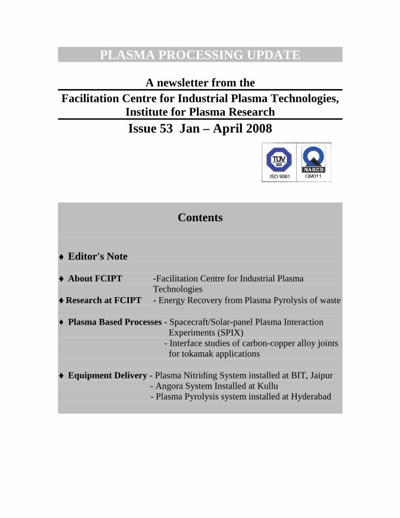
Another endeavour was to find a simple way of solving the differential equations developed by Cho [3], which relates the shapes of the oscilloscope traces of the primary arcs to the electrical parameters that make up the solar panel coupon, thereby gaining a deeper understanding of the arcing phenomenon. The results were in good agreement with the model developed [4] and the results from the SPIX experiments.
Fig. 1: SPIX experimental test facility at FCIPT
The experimental facility was developed (Fig. 1) at FCIPT for studying the primary and secondary arcing thresholds and their relation to the coupon configuration and identification of the arcing sites so as to arrive at mitigating techniques [5, 6]. Experiments were carried out in the actual SPIX setup on different types of solar cell coupons. In the first configuration, negative bias was applied after shorting both the ends of the solar array. In this configuration, decoupling mode (very large value of resistor to protect power supply) and current limiting mode (high impedance value resistor) have been used during the experiment. To simulate the space conditions inside the laboratory and to give negative voltage to the string, an external R-C circuit was connected with biasing power supply. In this type of configuration, only primary arcs were observed. With arc rate, current-time characteristics were also observed. The dependence of arc rate on biasing voltage, density and temperature was also studied numerically as well as experimentally.
In the second circuit configuration the potential was applied between two solar arrays to generate maximum potential difference. This configuration is more realistic compared to the first one, because in this type of configuration, to simulate actual solar conditions SAS (Solar Array Simulator) power supply was connected between two strings of the solar panel array. There was a maximum potential difference at the end of the ‘U’ string which was one of the main causes to generate or feed the secondary arc. Other circuit connections were same as the previous circuit configuration. In this configuration both type of arcs (primary and secondary) have been observed. The typical current-time characteristics of the arc have been observed and studied.
In addition to the above, experiments have also been performed to understand the phenomena and estimation of initiation of arc, sustenance of arc, arc duration, arc characteristics and damage due to arc. Voltage threshold for arc initiation phenomenon has been measured. Dependence of voltage threshold on solar cell string gap, solar cell material and design, grouting material, plasma condition, SAS voltage have been also studied. The laboratory finding combined with the observation of satellites power losses in orbit, put the reality and the harmfulness of the arc in space beyond any doubt. Damage analysis of solar panel coupons was done with the optical microscope images. Also optical and gas analyzer spectra was used to study damage in more detail. With this understanding, the following results and suggestions have been successfully delivered to ISAC/ISRO.
1. Software to understand the dynamics of electrical charging (absolute and differential charging) of objects in a space plasma environment.
2. Software to study arc initiation and sustenance. 3. To establish dependence of arc initiation on materials, configuration of
solar arrays and array electrical and plasma properties through experiments and codes developed.
4. To evaluate behaviour of material subjected to arcs through experiment. 5. To arrive at guidelines to choose solar array material, configuration and
electrical design that may survive the LEO environment through software and experiments developed at FCIPT.
References:
1. “Spacecraft Environment Interactions”, D. Hastings, H. Garrett, Cambridge University Press (1996)
2. “Design Guidelines for Assessing and Controlling Spacecraft Charging Effects”, C. K. Purvis, H. B. Garrett, NASA Technical Paper 2361 (1984)
3. Meng’u Cho, Arcing on High Voltage Solar Arrays in Low Earth Orbit: Theory and Computer Particle Simulation, Ph.D. Thesis (1992)
4. D. Hastings, M. Cho and H. Kuninaka, The arcing rate for a high voltage solar array: Theory, Experiment and Predictions, Jnl of Spacecraft & Rockets (1991)
5. D. B. Snyder, Discharge on a negatively biased solar array in a charged particle environment, Spacecraft environmental interaction technology (1983)
Interface studies of carbon-copper alloy joints for tokamak applications Dr. P. M. Raole is an expert in surface characterization and material physics.
Plasma facing components (PFC) are expected to withstand high thermal loads from magnetically confined high temperature plasma in a tokamak or a fusion reactor. PFC consists of Plasma facing material (Carbon, Tungsten, Beryllium) thermally attached to actively cooled heat-sink (Copper Alloy) material. Graphite and Carbon-Fiber-Composite are popular plasma facing materials and Cu-Cr-Zr (high strength copper alloy) is popular heat-sink material for PFC. Experiments have been initiated at IPR to develop Carbon-to-Copper joining techniques that can be implemented to fabricate PFC for steady-state heat flux removal up to 10 MW/m2. Graphite to Copper joints in small size (of 15 mm x 15 mm and 5 mm thick), have been fabricated using vacuum brazing furnace with brazing temperature of about 1040°C and TiCuSi1® as a brazing filler material in the form of 100 µm thick foil. The joints have been characterized using Scanning Electron Microscopy (Leo s-440i model), EDX mapping and X-Ray Diffraction using Cu-kα radiation (Seifert XRD3000PTS) at FCIPT. (A) Graphite-CuCrZr Joint
Fig. 1 shows X-Ray diffraction pattern taken after careful removal of the graphite material, in order to reach near to the interface. TiC phase formation is clearly seen along with the presence of C, Cu and Ag peaks [2]. No oxide formation of any elements is observed in the XRD pattern indicating the clean environment during brazing process. Fig. 2a shows SEM micrograph of the joint. Uniformity along the length of the joint is clearly observed without any voids and porosity. EDX mapping of Ag, Cu, Ti & Cr elements at the interface (about 1µm thick) is shown in Fig. 2b. Ti segregation is seen more towards copper side of the joint, probably because of higher solubility of Ti in Cu at brazing temperature of 1040°C used in the present experiment [1]. Mechanical shear strength measurements showed failure at 25 MPa on the graphite side keeping the joint intact. This indicates that joint is having strength higher than that of the graphite. The observed high strength has been attributed to TiC formation, improving wetting of Carbon and bonding at the interface.
Ti
Fig-1: X-Ray diffraction pattern of the Graphite-CuCrZr interface after removing graphite .
Fig-2a: SEM-SE image of Graphite-CuCrZr joint with TiCuSil foil
C
TiC TiC TiC
TiC
Ag Ag Ag A
g
Cu Cu
Cu Cu C
XRD of Graphite – CuCrZr joint
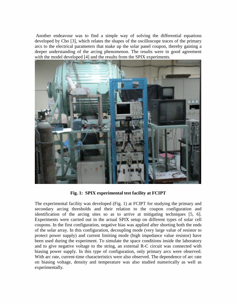
Fig-2b: EDX Mapping of Ag, Cu, Ti & Cr at the interface of Graphite-CuCrZr joint. (B) Graphite-OFHC-CuCrZr Joint
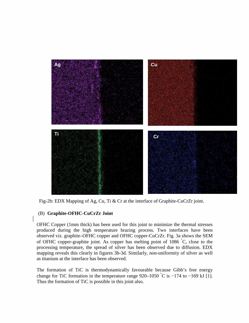
OFHC Copper (1mm thick) has been used for this joint to minimize the thermal stresses produced during the high temperature brazing process. Two interfaces have been observed viz. graphite–OFHC copper and OFHC copper-CuCrZr. Fig. 3a shows the SEM of OFHC copper-graphite joint. As copper has melting point of 1086 °C, close to the processing temperature, the spread of silver has been observed due to diffusion. EDX mapping reveals this clearly in figures 3b-3d. Similarly, non-uniformity of silver as well as titanium at the interface has been observed. The formation of TiC is thermodynamically favourable because Gibb’s free energy change for TiC formation in the temperature range 920–1050 °C is −174 to −169 kJ [1]. Thus the formation of TiC is possible in this joint also.
Ti Cr
Ag Cu
Ag Conclusion Thus, it has been found that characterization techniques such as SEM, EDX and XRD give crucial information about the interface of the brazed joints. CuCrZr alloy - graphite joint made using TiCuSil filler is very uniform, with minimum structural defects and having good strength. TiC formation observed in the CuCrZr alloy-graphite joint gives improved wettability thereby giving good strength due to bonding. TiCuSil brazed joint with OFHC copper gives broader elemental distribution due to higher solubility at high temperature. References:
Fig-3b: EDX mapping of Ag at the interface
Fig-3c: EDX mapping of Ti at the interface Fig-3d: EDX mapping of Cu at the interface
Fig-3a: SEM-SE image of Graphite-OFHC-CuCrZr joint with TiCuSil foil
1. Active metal brazing and characterization of brazed joints in titanium to carbon–carbon composites, M. Singh et al, Materials Science and Engineering A, 412 (2005) 123–128
2. Powder Diffraction Files No. 32-1383 (TiC), 41-1487 (C), 4-783 (Ag) JCPDS-International Center for Diffraction Data 1995, Pennsylvania 19073-3273,USA
Acknowledgement: The Author would like to acknowledge Dr. Sameer Khirwadkar (IPR) and Mr. N.L.Chauhan (FCIPT, IPR) for their major contribution and involvement in the work reported here.
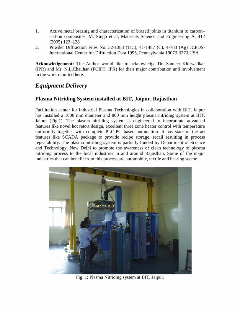
Equipment Delivery Plasma Nitriding System installed at BIT, Jaipur, Rajasthan Facilitation center for Industrial Plasma Technologies in collaboration with BIT, Jaipur has installed a 1000 mm diameter and 800 mm height plasma nitriding system at BIT, Jaipur (Fig.1). The plasma nitriding system is engineered to incorporate advanced features like novel hot retort design, excellent three zone heater control with temperature uniformity together with complete PLC-PC based automation. It has state of the art features like SCADA package to provide recipe storage, recall resulting in process repeatability. The plasma nitriding system is partially funded by Department of Science and Technology, New Delhi to promote the awareness of clean technology of plasma nitriding process to the local industries in and around Rajasthan. Some of the major industries that can benefit from this process are automobile, textile and bearing sector.
Fig. 1: Plasma Nitriding system at BIT, Jaipur.
Installation of an Atmospheric pressure Plasma System for of Angora Wool Processing at Kullu, Himachal Pradesh
FCIPT, Institute for Plasma Research has developed an atmospheric pressure glow discharge (APGD) system to improve cohesion among Angora wool in collaboration with National Institute of Design and Central Wool Development Board. The project has been funded under the DST’s programme “Surface Engineering for Rejunivation of Traditional Art & Craft”. After the process optimization and rigorous trials at FCIPT, the plasma system was shifted to Shiva Society, Kullu. FCIPT team which included Dr. S. K. Nema, R.S. Rane, Adam Sanghariat, Nisha Chandwani, Vijay Chauhan and Chirayu Patil has successfully installed and commissioned the system at Kullu in February 2008 (Fig.1). Mr. G. Gandhi from NID was also a member of the team. Angora fibers are obtained from the hair of a special breed of rabbits- known as Angora rabbits. This fiber is very warm, soft and is the lightest natural fiber known. However its smooth surface and fibrosity of fibers makes weaving very difficult with 100% Angora wool. In case, weaving is done, the shedding (loss) of these fibers takes place with time. Therefore, this wool is generally blended with superfine wool, mohair, silk, and alpaca to produce fashion garments. The atmospheric pressure plasma treatment of Angora wool has modified the surface of Angora fibers and it has eliminated the problem of fiber loss. Basically the plasma treatment for approximately one minute improves the coefficient of friction of fibers 3 times and it also imparts oxygen functionality ( -OH, - C=O) on the fiber surface which enhances cohesion among the fibers. The treatment helps in improving the weaving and also reduces shedding problem. The system can treat the wool continuously. The plasma treatment does significant value addition in the wool as one can produce garments with 100% Angora fibers.
Fig. 1: Atmospheric Pressure Plasma System Installed at Kullu Plasma Pyrolysis system installed at Hyderabad, Andhrapradesh FCIPT has installed two more prototype plasma pyrolysis systems for disposal of plastic and medical waste in G.B. Pant Hospital, Agartala and Gandhi Hospital, Hyderabad (Fig. 1) under the technology demonstration and promotion program of DST, New Delhi. The system disposes the waste in an environment friendly manner with the emission levels lower than the norms given by CPCB for incinerator technology. Plasma pyrolysis is a technique of disintegrating the longer chain of carbonaceous material for example, cellulose, plastic etc into lower hydrocarbon and other combustible gases form, for example CO, CH4, H2, C2H6 etc. This process occurs at higher than 650°C in the primary chamber. These combustible gases flow through a secondary chamber by means of an induced draft fan where air is mixed with these gases for combustion. The temperature of secondary chamber goes upto 1000°C. The residence time of gases in secondary chamber is around 1sec which is sufficient to break the dioxins and furans if formed in the primary chamber because of material like PVC etc. The flue gases after secondary chamber goes to scrubber unit where the temperature of hot gas is reduced to 70°C. The hot gas is then thrown in atmosphere by means of ID fan and chimney. The required height of the chimney in this system is less than 7 meters. The system can dispose 15 kg waste in an hour.
Fig. 1: Prototype plasma pyrolysis system for disposal of actual plastic and medical waste for demonstration and data collection in Gandhi hospital, Hyderabad
Facilitation Centre for Industrial Plasma Technologies