Mike Wise, Chief Metallurgist, Tetronics Ltd The Role of Radiochemistry in the Sentencing and Disposal of Radioactive Wastes Royal Society of Chemistry 7th April 2008 Plasma Processing of Nuclear Wastes
Transcript
Mike Wise, Chief Metallurgist, Tetronics Ltd
The Role of Radiochemistry in the Sentencing and Disposal of Radioactive Wastes
Royal Society of Chemistry7th April 2008
Plasma Processing of Nuclear Wastes
Plasma ProcessingPlasma Processing
• Tetronics Ltd.• What is plasma?• Plasma devices• Cold crucible melting• Slag design• Vitrified products• Vitrification v cementation• Caesium volatility
Tetronics Ltd.Tetronics Ltd.• Name from Tetra and Ionics• Founded in 1964 by three local businessmen• Privately owned company: Tetronics Holdings 2004• Main business is the application of plasma as a clean heat
source• Two spin off companies,
PRL and APP• Now located in Swindon• 50 employees• www.tetronics.com
What is Plasma?What is Plasma?• A plasma is an ionised gas comprising ions, molecules,
electrons, photons and atoms either in their ground states, or in various states of excitation: the fourth state of matter.
• Overall, a plasma is electrically neutral.• A plasma is electrically conducting, its resistance being a
function of its length, temperature and composition.• The power (temperature) of a plasma is determined by its
length (voltage), the type of gas used (voltage) and the applied current, which can be readily controlled.
As a gas is heated, collisions become more energetic and occur with greater frequency. At about 2,000 K molecules dissociate into their constituent atoms. At about 3,000 K the collision energies cause outer shell electrons to be ejected resulting in a plasma containing free electrical charges.
Plasma FormationPlasma Formation
• Electrically conductive• Intense heat and light
Weakening of bonds
Collision and breaking of bonds
Transfer of electrons
Electrons Plasma
Cathode
Anode
1,000K 3,000 ~4,000K 10,000K
-
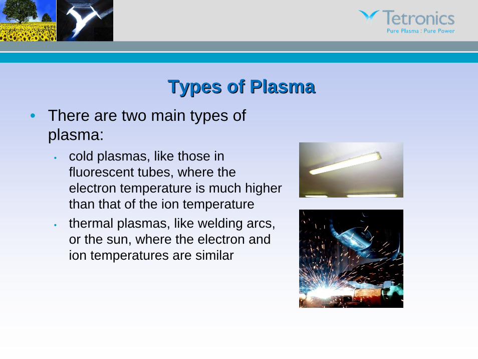
Types of PlasmaTypes of Plasma• There are two main types of
plasma:• cold plasmas, like those in
fluorescent tubes, where the electron temperature is much higher than that of the ion temperature
• thermal plasmas, like welding arcs, or the sun, where the electron and ion temperatures are similar
Effect of Temperature and Pressure on PlasmaEffect of Temperature and Pressure on Plasma
Te electron temperature
Tg ion temperature
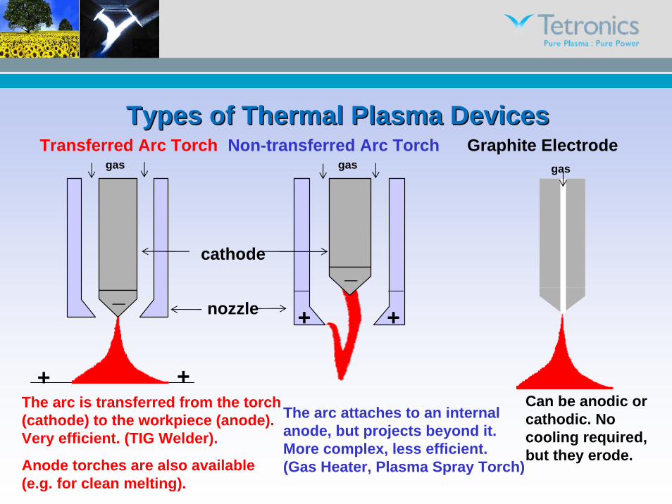
Types of Thermal Plasma DevicesTypes of Thermal Plasma DevicesNon-transferred Arc TorchTransferred Arc Torch Graphite Electrode
The arc is transferred from the torch (cathode) to the workpiece (anode). Very efficient. (TIG Welder).
Anode torches are also available (e.g. for clean melting).
The arc attaches to an internal anode, but projects beyond it. More complex, less efficient.(Gas Heater, Plasma Spray Torch)
Can be anodic or cathodic. No cooling required, but they erode.
gas gas gas
nozzle
cathode
+
++
+
__
Tetronics Plasma SystemsTetronics Plasma Systems• Tetronics use transferred arc devices, which means
that a return electrode is required when a single, transferred-arc plasma device is used
• For conducting melts the return path is via an anode in the base of the furnace
• For non-conducting melts, such as glasses or wastes, Tetronics use a twin electrode system in which the plasma is generated in free space above the melt
• This means that no return electrode is required in the base of the crucible and plasma restart with graphite electrodes is simply achieved by a touch start
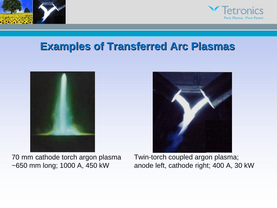
Examples of Transferred Arc PlasmaExamples of Transferred Arc Plasmass
70 mm cathode torch argon plasma~650 mm long; 1000 A, 450 kW
Some Plasma FactsSome Plasma Facts• Think of it as a high-temperature electric flame (10,000 ºC)• It is controllable, clean and has a low gas volume• Thermal plasmas can be generated by water-cooled
torches or graphite electrodes• For waste processing, graphite electrodes are practical as
they are cheaper and do not require water cooling• Argon is the most commonly used plasma torch gas but,
for waste processing with graphite electrodes, nitrogen can be used (cheaper)
• Graphite electrodes wear by erosion but can be continuously replaced (as in the steel and aluminium industries)
Cold Crucible ContainmentCold Crucible Containment• For clean melting, and for nuclear waste processing, the melt is
contained in a water-cooled, ‘cold-wall’, copper crucible.• In cold crucible melting, the melt is contained in a thin solid layer of
its own composition (a skull) and so is not contaminated by the cold crucible, and vice versa.
• This means that there are no problems of contamination of the containment vessel by the absorption of radionuclides (as there are with refractory-lined, ‘hot-wall’ vessels).
• The cold crucible does not wear, and the non-volatile, inorganic fraction of the melt composition remains essentially constant, thereby allowing omnivorous solvent melts (slags or fluxes) of the desired chemistry, melting point and fluidity to be designed.
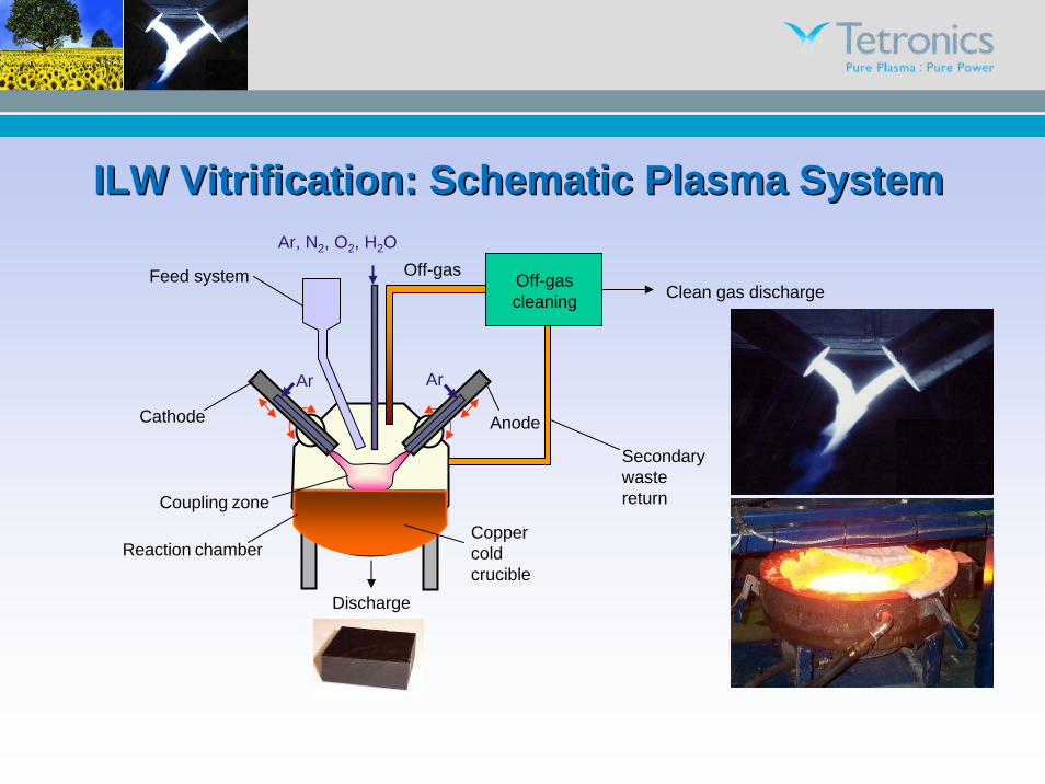
ILW Vitrification: Schematic Plasma SystemILW Vitrification: Schematic Plasma System
• Sludges #2 and #3 are mainly magnesium hydroxide, from the corrosion of Magnox cans, and sludge #4 is a mixture of sand and clinoptilolite, a zeolite ion exchange medium.
• The main radionuclides present are Sr90 and Cs137 plus some fuel residues.
• The current technology is to add cement to the sludges then pourthe resultant concrete into RWMD containers for storage.
• Vitrifying the sludges, however, would reduce the volume of material to be stored, so requiring fewer containers and less storage volume, with consequent cost savings.
Vitrification of ILW Sludges (2)Vitrification of ILW Sludges (2)• Vitrification also oxidises all of the constituents thereby avoiding some
cement encapsulation problems (organics; Mg + H2O→H2 evolution).• The vitrified product is stable and chemically inert; it’s a glass .• A problem with high-magnesia content sludges is that that they need
additions of fluxing agents in order to produce slags with melting points and viscosities that enable easy casting. (MgO; M.P. 2831 °C)
• Hence, target slag compositions were designed using MgO-Al2O3-SiO2ternary phase diagrams to optimise these requirements whilst incorporating high levels of magnesia with a wide band of tolerance.
• Simulant slags were made up using magnesium hydroxide/carbonate,silica, alumina, sodium hydroxide solution and clinoptilolite (as appropriate) according to the chemical analyses supplied.
• These were doped with Sr and Cs at ~100 times the sludge analysis and ceria was added to simulate the actinide content.
Sludge #3 WasteSludge #3 Waste--Form Design and ResultsForm Design and ResultsSpecies Analysis%
H2O 40.0
Mg(OH)2 48.0
UO2 7.5
Al2O3 0.5
cellulose 4.0
Total 100.0
Species Analysis%
Na2O 0.17
MgO 20.90
Al2O3 18.30
SiO2 54.55
K2O 0.06
CaO 0.29
TiO2 0.79
Fe2O3 0.79
La2O3 0.20
CeO2 4.76
Total 100.81
21% MgO
55% SiO2
18% Al2O3
Analysed waste-form composition of high-magnesia simulant sludge
Species Analysis%
MgO 20.8
Al2O3 23.4
SiO2 51.1
CeO2 4.7
Total 100.0
Sludge #3 analysis
Target composition
Ternary phase diagram suggests the slag to be near the cordierite-protoenstatite-forsterite eutectic with a liquidus temperature ~1365 °C
This X-ray diffraction pattern of the final waste-form of sludge #3 shows that none of the lines from the original feedstock phases is present confirming that complete reaction has occurred. 40% water content; 49% flux addn. to sludge27% volume reduction
Because of the rapid cooling effect of the cold crucible, the waste-form has solidified as a glass rather than as a crystalline solid. This is confirmed by the X-ray diffraction pattern. Density of sludge = 1400 kg m-3
Density of glass = 2690 kg m-3
Self FluxingSelf Fluxing• The addition of fluxing agents could be avoided by mixing together
sludges of appropriate compositions.• The following data refer to the processing of a mixture of simulant
sludges: sludge #3, with a high magnesia content, and sludge #4,sand/clinoptilolite, in the proportions in which they could arise.
Species Analysis%
H2O 27.9
Mg(OH)2 5.0
SiO2 8.0
NaOH 9.1
clinoptilolite 50.0
Total 100.0
Species Analysis%
H2O 40.0
Mg(OH)2 48.0
UO2 7.5
Al2O3 0.5
cellulose 4.0
Total 100.0
Sludge #4 sand/clinoptilolite 20 m3/day
Sludge #3 high magnesia 16 m3/day
Species Analysis%
H2O 12.4
CaO 1.8
Al2O3 10.9
SiO2 64.0
NaOH 2.9
K2O 1.6
Clinoptilolite analysis
Blending Sludges #3 and #4 for Self FluxingBlending Sludges #3 and #4 for Self FluxingSpecies Analysis%
Na2O 9.0
MgO 24.6
Al2O3 7.6
SiO2 50.9
K2O 0.9
CaO 1.5
Fe2O3 0.9
CeO2 4.7
others 0.5
Total 100.6
24.6% MgO
7.6% Al2O3
50.9% SiO2
Analysed waste-form composition of mixed simulant sludges (major elements)
Feed composition of mixed simulant sludges #3 and #4
Mixed Sludges #3 and #4: ProductMixed Sludges #3 and #4: Product
This X-ray diffraction pattern of the final waste-form shows it to consist of forsterite and glass. Forsterite was not present in the start material, and none of the lines from the original feedstock phases is present, confirming that complete reaction has occurred.
Because of the higher melting point and wider melting range, the waste-form has solidified as a semi-crystalline solid. This is confirmed by the X-ray diffraction pattern.Density = 2690 kg m-3
Cementation v VitrificationCementation v VitrificationTo illustrate the scale of these reductions, comparisons between cementation and plasma vitrification for 10 volumes each of sludge #2 and sludge #4 are shown below.
Density of sludge #2 ~1300 kg m-3
Density of glass = 2640 kg m-3
60% water content; 32% flux addition to sludge64% volume reduction
Density of sludge #4 = 1600 kg m-3
Density of glass = 2340 kg m-3
30% water content; no flux addition to sludge59% volume reduction
• Unit cost of packaging (Drums and Stillage) £10,000
• Cost of Packaging £300,000,000
• 50 year life cycle cost for one store £200,000,000
• Cost for Interim Stores £923,000,000
• Cost of one transport flask £750,000
• No of flasks per store (Export 2 per day) 12
• Cost of Flasks (Capex) £42,000,000
• Nominal cost of single flask round trip £1,000
• Cost of Transport to Store & to Repository £60,000,000
• Total Cost up to Repository Gate £1,325,000,000
Plasma£10,000
£65,000,000
£200,000,000
£200,000,000
£750,000
12
£9,000,000
£1,000
£13,000,000
£287,000,000
ILW Vitrification SummaryILW Vitrification Summary• Heating in the twin arc plasma furnace drives off the water, oxidises the
carbonaceous materials and converts the inorganic solids into a homogeneous melt
• On cooling, this forms an inert, stable waste-form of higher density and of lower volume than the original sludge
• For example, 100 kg of Magnox simulant sludge plus fluxes produced 73.6 kg of waste-form; the density of the settled sludge was ~1300 kg m-3
and the density of the waste-form was 2640 kg m-3 resulting in a net volume reduction of 64%.
• A net reduction in volume was obtained for all of the simulant sludges processed, the value of which varied from 27% to 64% depending on the magnesia content of the sludge and the amount of flux required.
• Therefore, by using plasma processing the number of storage containers and, hence, repository costs, would be reduced dramatically compared with using cement encapsulation.
Caesium volatilityCaesium volatility
• Melts containing alkali metals will suffer evaporative loss depending on the temperature to which they are raised.
• This is a particular problem for melts containing 137Cs and other volatile radionuclide isotopes, particularly if high intensity heat sources such as electron beam, lasers or plasma are used.
• The loss of volatiles from a melt can be minimised by appropriate design of the melting system and the slag chemistry.
Potential Advantages of Potential Advantages of TetronicsTetronics’’ ProcessProcess• The Tetronics process uses twin graphite electrodes with indirect
plasma heating and no plasma hot spot.• Twin graphite electrodes enable a plasma ‘touch start’.• The cold crucible process avoids cross contamination.• The high silica content, low basicity, of Tetronics’ melts should be a
significant factor in retaining caesium and other network formers, such as strontium.
• Silica rich slags suffer less volatile loss than borosilicate glasses at equivalent viscosities.
• Silica rich slags are much more viscous than borosilicate glasses at equivalent temperatures, which should reduce volatile losses.