+12VDC Platform # 02 Firmware: HODL Description: Honda/Acura Doorlock Alarm Interface (NO KEY REQUIRED) Functions: Lock/Unlock, Trunk, OEM Security Arm/Disarm Downloadable Firmware for Platform #02: HODL, NISSDL, SUBDL DATA to DATA PORT (D2D): of D2D Cable plugs into the upgradeable vehicle interface module. OPTION A: - D2D Port used to connect to USB Bootloader adaptor & computer to download & flash vehicle interface firmware. OPTION B: - D2D Port used to connect to the data port of a remote control system equipped with ClearCode Vehicle Interface Protocol. Remote control systems designed with ClearCode VIP can securely communicate via the D2D cable to transmit & receive data commands which initiate specific vehicle function such as doorlocks & immobilizer override and /or request information from the vehicle such as status of entry points (doors) or ambiant température, diesel glow plug etc… ClearCode VIP represents the doorway to vehicle integration... Blue connector Legend RCS = Remote Control System N/C = No Connection N/A = Not Applicable W2W= analogue wire to wire D2D= data 2 data (-) /(+) (-) VEHICLE TYPE Input Input Input Input Input Data (-) WIRE COLOR Brown Green Blue Violet/ White Violet Pink/ White Pink Orange Red Black (-) (+) SPECIFIC WIRE CONNECTION LOCATION Constant (+) 12 Volt Source Chassis Ground Connect Location RCS RCS Vehicle Vehicle Vehicle (-) ACTIVATION and/or FUNCTIONALITY Lock All Doors Unlocks All Doors RCS N/A Power Source Ground Source WIRE GUIDE: CONNECTIONS Section B PIN# 1 2 3 4 5 6 7 8 9 10 Ground When Running output of remote starter D2D w2w D2D w2w 10 PIN HARNESS I/O STATUS Red Green Blue Violet Black Violet/White Pink Pink/White Chassis Ground (+)12 Volt Constant Unlock Lock Brown Ground When Running D2 D 10 PIN H ARNESS INPUT INPUT INPUT INPUT INPUT (-) (+) (-) (-) (-) 4 PIN DATA TO DATA (D2D) CABLE (OPTIONAL ACCESSORY) Data (See Wire Guide) See Wire Connection Guide for detailed information regarding wire functionality P.C. USB Adaptor USB Cable Option A Firmware Upgrades Blue Brown CLEARCODE VIP DATA PORT Option B - Data 2 Data Connection to RCS Data Port Section A Vehicle Door Pin Switch (See Wire Guide) OEM Alarm Ignition (See Wire Guide) Trunk D2 D LED Programming button Internet UPGRADEABLE DOOR LOCK & OEM ALARM INTERFACE MODULE (-) OUTPUT DATA OEM Alarm Ignition (See Wire Guide) INPUT (-) Orange (+) (+) OUTPUT INPUT Output (-) Vehicle Vehicle RCS Input (-) N/A N/A N/A N/A Connect to (-) Lock Output wire of RCS Connect to (-) Unlock Output wire of RCS Connect to Green/Orange wire, fuse box side (See Vehicle Type Diagram for Connections) Supplies (-) output to vehicle door pin switch in order to arm OEM alarm (See Vehicle Type Diagram for Connections) OEM Alarm Ignition Input (See Vehicle Type Diagram for Connections) Output Input (+) See Vehicle Type Diagram Acura 1.7 ONLY Connect to (-) Trunk Release Output wire of RCS Trunk Release *Acura 1.7 ONLY OEM Security Arm/Disarm OEM Alarm Ignition Output (See Vehicle Type Diagram for Connections) Ignition Power to Alarm Module Ignition from Vehicle Harness Lock/Unlock/Arm/Disarm Via Vehicle Data Wire See Vehicle Type Diagram See Vehicle Type Diagram See Vehicle Type Diagram Vehicle D2D w2w D2D w2w w2w w2w w2w D2D w2w D2D w2w D2D w2w D2D = Optional use of 4 Pin Data to Data (D2D) cable will replace the analogue wire (w2w) connection w2w (+)
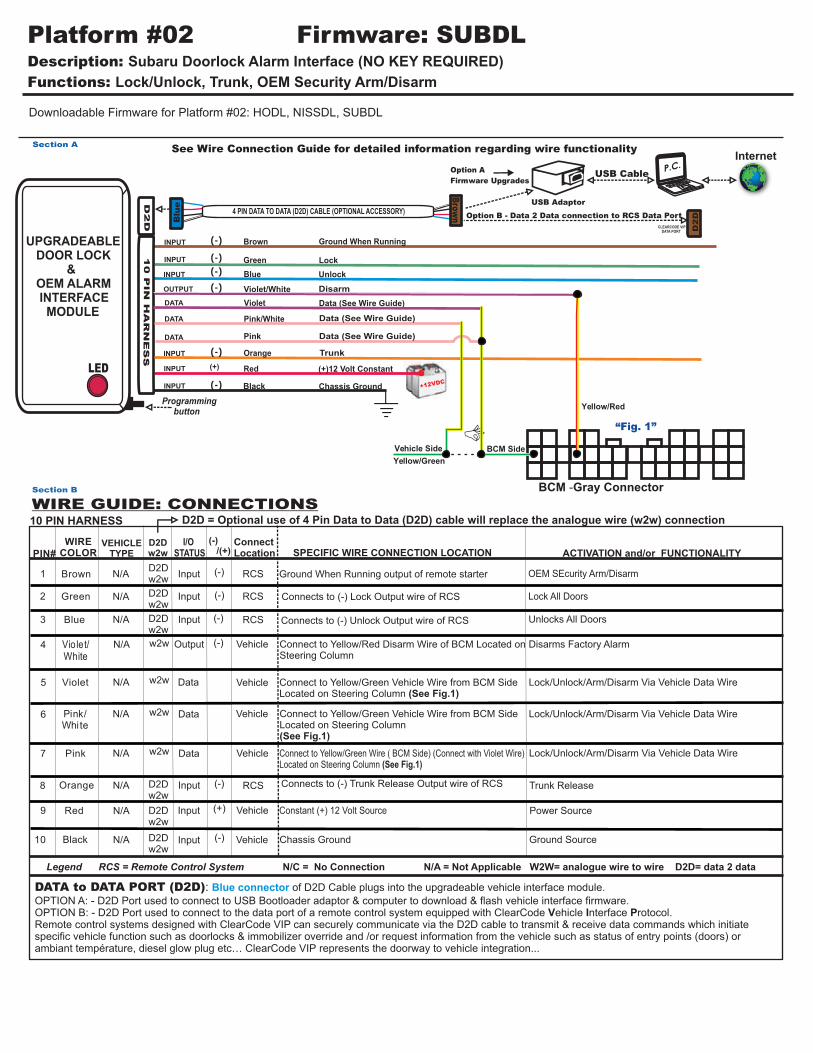
Downloadable Firmware for Platform #02: HODL, NISSDL, SUBDL
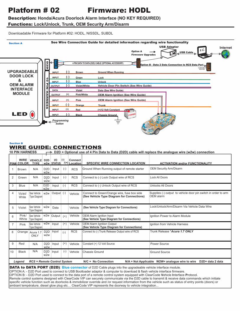
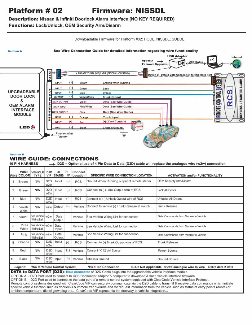
DATA to DATA PORT (D2D): of D2D Cable plugs into the upgradeable vehicle interface module.
OPTION A: - D2D Port used to connect to USB Bootloader adaptor & computer to download & flash vehicle interface firmware.OPTION B: - D2D Port used to connect to the data port of a remote control system equipped with ClearCode Vehicle Interface Protocol.Remote control systems designed with ClearCode VIP can securely communicate via the D2D cable to transmit & receive data commands which initiate specific vehicle function such as doorlocks & immobilizer override and /or request information from the vehicle such as status of entry points (doors) or ambiant température, diesel glow plug etc… ClearCode VIP represents the doorway to vehicle integration...
Blue connector
Legend RCS = Remote Control System N/C = No Connection N/A = Not Applicable W2W= analogue wire to wire D2D= data 2 data
(-) /(+)
(-)
VEHICLE TYPE
Input
Input
Input
Input
Input
Data
(-)
WIRECOLOR
Brown
Green
Blue
Violet/White
Violet
Pink/White
Pink
Orange
Red
Black (-)
(+)
SPECIFIC WIRE CONNECTION LOCATION
Constant (+) 12 Volt Source
Chassis Ground
ConnectLocation
RCS
RCS
Vehicle
Vehicle
Vehicle
(-)
ACTIVATION and/or FUNCTIONALITY
Lock All Doors
Unlocks All Doors
RCSN/A
Power Source
Ground Source
WIRE GUIDE: CONNECTIONS Section B
PIN#
1
2
3
4
5
6
7
8
9
10
Ground When Running output of remote starter
D2D w2w
D2Dw2w
10 PIN HARNESS
I/O STATUS
Red
Green
Blue
Violet
Black
Violet/White
Pink
Pink/White
Chassis Ground
(+)12 Volt Constant
Unlock
Lock
Brown Ground When Running
D2D
10 P
IN
HA
RN
ES
S
INPUT
INPUT
INPUT
INPUT
INPUT (-)
(+)
(-)
(-)
(-)
4 PIN DATA TO DATA (D2D) CABLE (OPTIONAL ACCESSORY)
Data (See Wire Guide)
See Wire Connection Guide for detailed information regarding wire functionality
P.C.USB Adaptor
USB CableOption A
Firmware UpgradesB
lue
Brow
n
CLEARCODE VIP DATA PORT
Option B - Data 2 Data Connection to RCS Data Port
Section A
Vehicle Door Pin Switch (See Wire Guide)
OEM Alarm Ignition (See Wire Guide)
Trunk
D2D
LEDProgramming button
Internet
UPGRADEABLE DOOR LOCK & OEM ALARM INTERFACE MODULE
(-)OUTPUT
DATA
OEM Alarm Ignition (See Wire Guide)
INPUT (-) Orange
(+)
(+)OUTPUT
INPUT
Output (-)
Vehicle
Vehicle
RCSInput (-)
N/A
N/A
N/A
N/A
Connect to (-) Lock Output wire of RCS
Connect to (-) Unlock Output wire of RCS
Connect to Green/Orange wire, fuse box side(See Vehicle Type Diagram for Connections)
Supplies (-) output to vehicle door pin switch in order to arm OEM alarm
(See Vehicle Type Diagram for Connections)
OEM Alarm Ignition Input (See Vehicle Type Diagram for Connections)
Output
Input
(+)
See Vehicle Type Diagram
Acura 1.7 ONLY
Connect to (-) Trunk Release Output wire of RCS Trunk Release *Acura 1.7 ONLY
OEM Security Arm/Disarm
OEM Alarm Ignition Output(See Vehicle Type Diagram for Connections)
Ignition Power to Alarm Module
Ignition from Vehicle Harness
Lock/Unlock/Arm/Disarm Via Vehicle Data Wire
See Vehicle Type Diagram
See Vehicle Type Diagram
See Vehicle Type Diagram
Vehicle
D2Dw2w
D2Dw2w
w2w
w2w
w2w
D2Dw2w
D2Dw2w
D2Dw2w
D2D = Optional use of 4 Pin Data to Data (D2D) cable will replace the analogue wire (w2w) connection
Functions: Lock/Unlock, Trunk, OEM Security Arm/DisarmSection C
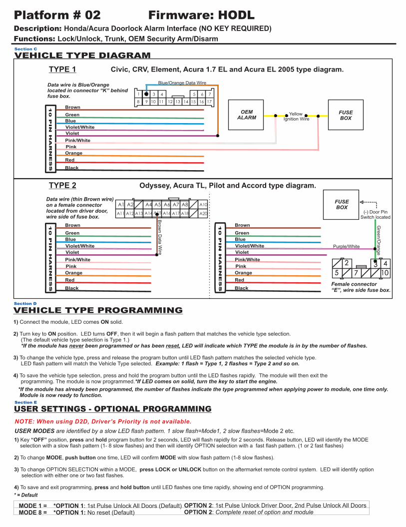
VEHICLE TYPE DIAGRAM
Civic, CRV, Element, Acura 1.7 EL and Acura EL 2005 type diagram.
Yellow Ignition Wire
FUSEBOX
Data wire is Blue/Orange located in connector “K” behindfuse box.
OEMALARM
1 2 3
10 11 12 13 14 15 16 17
4 65 7
8 9
TYPE 1
10 P
IN
H
AR
NE
SS
Blue/Orange Data Wire
Brown
Black
Orange
Blue
Green
Pink
Pink/White
Violet/White
Violet
Red
Odyssey, Acura TL, Pilot and Accord type diagram.
Data wire (thin Brown wire) on a female connector located from driver door, wire side of fuse box.
TYPE 2
Bro
wn D
ata
Wire
A1 A2 A10
A11 A12 A13 A14 A15 A16 A17 A18 A20
A4 A5 A6 A7 A8
10 P
IN
H
AR
NE
SS
Brown
Black
Orange
Blue
Green
Pink
Pink/White
Violet/White
Violet
Red
1) Connect the module, LED comes ON solid. 2) Turn key to ON position. LED turns OFF, then it will begin a flash pattern that matches the vehicle type selection. (The default vehicle type selection is Type 1.) *If the module has never been programmed or has been reset, LED will indicate which TYPE the module is in by the number of flashes.
3) To change the vehicle type, press and release the program button until LED flash pattern matches the selected vehicle type. LED flash pattern will match the Vehicle Type selected. Example: 1 flash = Type 1, 2 flashes = Type 2 and so on.
4) To save the vehicle type selection, press and hold the program button until the LED flashes rapidly. The module will then exit the programming. The module is now programmed.*If LED comes on solid, turn the key to start the engine.
VEHICLE TYPE PROGRAMMINGSection D
*If the module has already been programmed, the number of flashes indicate the type programmed when applying power to module, one time only. Module is now ready to function.
MODE 1 = MODE 8 = *OPTION 1: No reset (Default)
*OPTION 1: 1st Pulse Unlock All Doors (Default) OPTION 2: 1st Pulse Unlock Driver Door, 2nd Pulse Unlock All DoorsOPTION 2: Complete reset of option and module
* = Default
USER SETTINGS - OPTIONAL PROGRAMMING
USER MODES are identified by a slow LED flash pattern. 1 slow flash=Mode1, 2 slow flashes=Mode 2 etc.
Section E
NOTE: When using D2D, Driver’s Priority is not available.
1) Key “OFF” position, press and hold program button for 2 seconds, LED will flash rapidly for 2 seconds. Release button, LED will identify the MODE selection with a slow flash pattern (1- 8 slow flashes) and then will identify OPTION selection with a fast flash pattern. (1 or 2 fast flashes)
2) To change MODE, push button one time, LED will confirm MODE with slow flash pattern (1-8 slow flashes).
3) To change OPTION SELECTION within a MODE, press LOCK or UNLOCK button on the aftermarket remote control system. LED will identify option selection with either one or two fast flashes.
4) To save and exit programming, press and hold button until LED flashes one time rapidly, showing end of OPTION programming.
Downloadable Firmware for Platform #02: HODL, NISSDL, SUBDL
Red
Green
Blue
Violet
Black
Violet/White
Pink
Pink/White
Chassis Ground
(+)12 Volt Constant
Unlock
Programming button
Lock
Brown Ground When Running
D2D
LED
10 P
IN
HA
RN
ES
S
INPUT
INPUT
INPUT
INPUT
INPUT
DATA
(-)
(+)
(-)
(-)
(-)
4 PIN DATA TO DATA (D2D) CABLE (OPTIONAL ACCESSORY)
Data (See Wire Guide)
See Wire Connection Guide for detailed information regarding wire functionality
P.C.
USB Adaptor
USB CableOption A
Firmware UpgradesB
lue
Brow
n
CLEARCODE VIP DATA PORT
Section A
Disarm
Data (See Wire Guide)
Data (See Wire Guide)
Trunk
D2D
DATA to DATA PORT (D2D): of D2D Cable plugs into the upgradeable vehicle interface module.
OPTION A: - D2D Port used to connect to USB Bootloader adaptor & computer to download & flash vehicle interface firmware.OPTION B: - D2D Port used to connect to the data port of a remote control system equipped with ClearCode Vehicle Interface Protocol.Remote control systems designed with ClearCode VIP can securely communicate via the D2D cable to transmit & receive data commands which initiate specific vehicle function such as doorlocks & immobilizer override and /or request information from the vehicle such as status of entry points (doors) or ambiant température, diesel glow plug etc… ClearCode VIP represents the doorway to vehicle integration...
Blue connector
Legend RCS = Remote Control System N/C = No Connection N/A = Not Applicable W2W= analogue wire to wire D2D= data 2 data
(-) /(+)
(-)
VEHICLE TYPE
Input
Input
Input
Input
Input
Data
(-)
WIRECOLOR
Brown
Green
Blue
Violet/White
Violet
Pink/White
Pink
Orange
Red
Black (-)
(+)
SPECIFIC WIRE CONNECTION LOCATION
Constant (+) 12 Volt Source
Chassis Ground
ConnectLocation
RCS
RCS
Vehicle
Vehicle
Vehicle
(-)
ACTIVATION and/or FUNCTIONALITY
Lock All Doors
Unlocks All Doors
RCSN/A
Power Source
Ground Source
WIRE GUIDE: CONNECTIONS Section B
PIN#
1
2
3
4
5
6
7
8
9
10
Ground When Running output of remote starter
D2D w2w
D2Dw2w
10 PIN HARNESS
I/O STATUS
OUTPUT
DATA
DATA
INPUT (-) Orange
BYellow/Green
BCM -Gray Connector
Yellow/Red
RCS(-)Input
Data
Data
Vehicle
Vehicle
N/A
N/A
N/A
N/A
N/A
N/A
N/A
N/A
N/A
Output (-) Vehicle
Trunk Release
Connect to Yellow/Red Disarm Wire of BCM Located on Steering Column
Disarms Factory Alarm
Connect to Yellow/Green Vehicle Wire from BCM SideLocated on Steering Column (See Fig.1)
“Fig. 1”
Connect to Yellow/Green Vehicle Wire from BCM Side Located on Steering Column(See Fig.1)
Connect to Yellow/Green Wire ( BCM Side) (Connect with Violet Wire) Located on Steering Column (See Fig.1)
OEM SEcurity Arm/Disarm
Vehicle Side BCM Side
Lock/Unlock/Arm/Disarm Via Vehicle Data Wire
Lock/Unlock/Arm/Disarm Via Vehicle Data Wire
Lock/Unlock/Arm/Disarm Via Vehicle Data Wire
Connects to (-) Unlock Output wire of RCS
Connects to (-) Lock Output wire of RCS
Connects to (-) Trunk Release Output wire of RCS
(-)
D2D = Optional use of 4 Pin Data to Data (D2D) cable will replace the analogue wire (w2w) connection
D2Dw2w
D2Dw2w
w2w
w2w
w2w
w2w
D2Dw2w
D2Dw2w
D2Dw2w
Internet
Option B - Data 2 Data connection to RCS Data Port
UPGRADEABLE DOOR LOCK & OEM ALARM INTERFACE MODULE
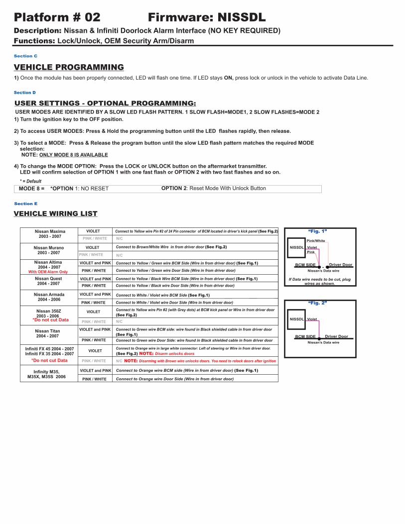
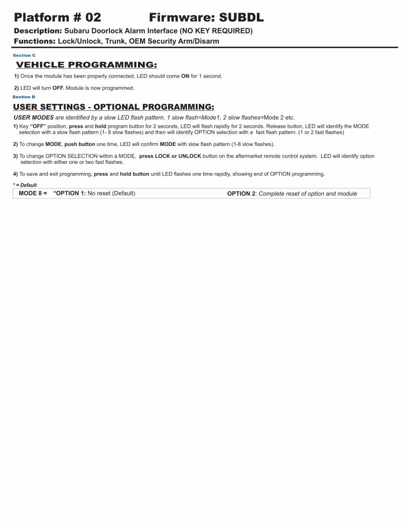
1) Once the module has been properly connected, LED should come ON for 1 second.
2) LED will turn OFF. Module is now programmed.
Section C
MODE 8 = *OPTION 1: No reset (Default) OPTION 2: Complete reset of option and module
* = Default
USER SETTINGS - OPTIONAL PROGRAMMING: USER MODES are identified by a slow LED flash pattern. 1 slow flash=Mode1, 2 slow flashes=Mode 2 etc.
Section D
1) Key “OFF” position, press and hold program button for 2 seconds, LED will flash rapidly for 2 seconds. Release button, LED will identify the MODE selection with a slow flash pattern (1- 8 slow flashes) and then will identify OPTION selection with a fast flash pattern. (1 or 2 fast flashes)
2) To change MODE, push button one time, LED will confirm MODE with slow flash pattern (1-8 slow flashes).
3) To change OPTION SELECTION within a MODE, press LOCK or UNLOCK button on the aftermarket remote control system. LED will identify option selection with either one or two fast flashes.
4) To save and exit programming, press and hold button until LED flashes one time rapidly, showing end of OPTION programming.
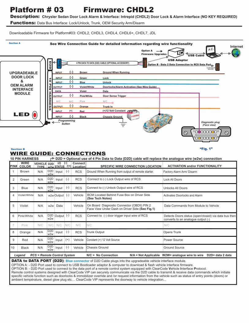
Description: Chrysler Sedan Door Lock Alarm & Interface: Intrepid (CHDL2) Door Lock & Alarm Interface (NO KEY REQUIRED)
Functions: Data Bus Interface: Lock/Unlock, Trunk, OEM Security Arm/Disarm
Platform # 03 Firmware: CHDL2
Red
Orange
Green
Blue
Violet
Black
Violet/White
Pink
Pink/White
Chassis Ground
(+)12 Volt Constant
Trunk In
N/C
Doorlocks/Alarm Activation (See Wire Guide)
Unlock
Programming button
Lock
Brown Ground When Running
D2D
INPUT
INPUT
INPUT
INPUT
INPUT
DATA
(-)
(+)
(-)
(-)
(-)
(-)
4 PIN DATA TO DATA (D2D) CABLE (OPTIONAL ACCESSORY)
(-)
(-)
Data
See Wire Connection Guide for detailed information regarding wire functionality
P.C.
USB Adaptor
USB Cable
Option A
Firmware Upgrades
D2DBlu
e
Brow
n
CLEARCODE VIP DATA PORT
Legend RCS = Remote Control System N/C = No Connection N/A = Not Applicable W2W= analogue wire to wire D2D= data 2 data
(-) /(+)
(-)
VEHICLE TYPE
Input
Input
Input
Input
Input
Input
Data
(-)
WIRECOLOR
Brown
Green
Blue
Violet/White
Violet
Pink/White
Pink
Orange
Red
Black
(-)
(-)
(+)
SPECIFIC WIRE CONNECTION LOCATION
BCM Located Behind Fuse Box on Driver Side(See Tech Notes)
Trunk Output
Constant (+) 12 Volt Source
Chassis Ground
ConnectLocation
RCS
RCS
RCS
Vehicle
Vehicle
Vehicle
(-)
ACTIVATION and/or FUNCTIONALITY
Factory Alarm Arm/ Disarm
Lock All Doors
Unlocks All Doors
Opens Trunk
RCSN/A
N/A
N/A
N/A
N/A
N/A
N/C
N/A
N/A
N/A
Power Source
Ground Source
WIRE GUIDE: CONNECTIONS Section B
Ground When Running from output of remote starter.
PIN#
1
2
3
4
5
6
7
8
9
10
N/CN/C
Diagnostic plug (Face view)
“Fig. 1”
Downloadable Firmware for Platform#03: CHDL2, CHDL3, CHDL4, CHDL6+, CHDL7, JDL
(-) RCSOutput
N/C N/C N/C N/C N/C
Section A
OUTPUT
OUTPUT
Output (-) Vehicle Activates Doorlocks and Alarm
Internet
DATA to DATA PORT (D2D): of D2D Cable plugs into the upgradeable vehicle interface module.
OPTION A: - D2D Port used to connect to USB Bootloader adaptor & computer to download & flash vehicle interface firmware.OPTION B: - D2D Port used to connect to the data port of a remote control system equipped with ClearCode Vehicle Interface Protocol.Remote control systems designed with ClearCode VIP can securely communicate via the D2D cable to transmit & receive data commands which initiate specific vehicle function such as doorlocks & immobilizer override and /or request information from the vehicle such as status of entry points (doors) or ambient température, diesel glow plug etc… ClearCode VIP represents the doorway to vehicle integration...
Blue connector
10 PIN HARNESS
D2Dw2w
I/O STATUS
N/C
Detects Doors status (open/closed) via data bus then converts to an analogue output (-)
On Board Diagnostic Connector (OBDII) PIN 2Face View Under Dash on Driver Side (See Fig.1)
Data Commands from Module to Vehicle
OUTPUT
Connect to (-) door trigger input wire of RCS
Connect to (-) Lock Output wire of RCS
Connect to (-) Unlock Output wire of RCS
Option B - Data 2 Data Connection to RCS Data Port
Door Sense Trigger
+12VDC
10 P
IN
HA
RN
ES
S
LED
UPGRADEABLE DOOR LOCK & OEM ALARM INTERFACE MODULE
D2D = Optional use of 4 Pin Data to Data (D2D) cable will replace the analogue wire (w2w) connection
D2Dw2w
D2Dw2w
D2Dw2w
D2Dw2w
w2w
w2w
D2Dw2w
D2Dw2w
D2Dw2w
Description: Chrysler Sedan Door Lock Alarm & Interface: Intrepid (CHDL2) Door Lock & Alarm Interface (NO KEY REQUIRED)
Functions: Data Bus Interface: Lock/Unlock, Trunk, OEM Security Arm/Disarm
Platform # 03 Firmware: CHDL2
VEHICLE PROGRAMMING:
1) Connect the module, LED will goes on.
2) Turn key ON, LED will turn off. Module is now programmed.
Section C
MODE 7 = MODE 8 = *OPTION 1: No reset (Default)
*OPTION 1: Vehicle with alarm (Default) OPTION 2: Vehicle without alarmOPTION 2: Complete reset of option and module
* = Default
USER SETTINGS - OPTIONAL PROGRAMMING:
USER MODES are identified by a slow LED flash pattern. 1 slow flash=Mode1, 2 slow flashes=Mode 2 etc.
Section D
NOTE: Only MODES 7 & 8 are available.
1) Key “OFF” position, press and hold program button for 2 seconds, LED will flash rapidly for 2 seconds. Release button, LED will identify the MODE selection with a slow flash pattern (1- 8 slow flashes) and then will identify OPTION selection with a fast flash pattern. (1 or 2 fast flashes)
2) To change MODE, push button one time, LED will confirm MODE with slow flash pattern (1-8 slow flashes).
3) To change OPTION SELECTION within a MODE, press LOCK or UNLOCK button on the aftermarket remote control system. LED will identify option selection with either one or two fast flashes. 4) To save and exit programming, press and hold button until LED flashes one time rapidly, showing end of OPTION programming.
TECH NOTES FOR VIOLET/WHITE WIRE
DO NOT ADD RESISTOR’S AS THEY ARE INTERNALDOORLOCKS/ALARM ACTIVATION WIRESEBRING SEDAN: White/Dark Green at BCMALL OTHER MODELS: Light Green/Orange at BCM
IMPORTANT:*On Sebring and Stratus Coupes, you can NOT control the alarm.*On Sebring and Stratus Sedan, you CAN control the alarm.*Do not install module on a metal service.
Section E
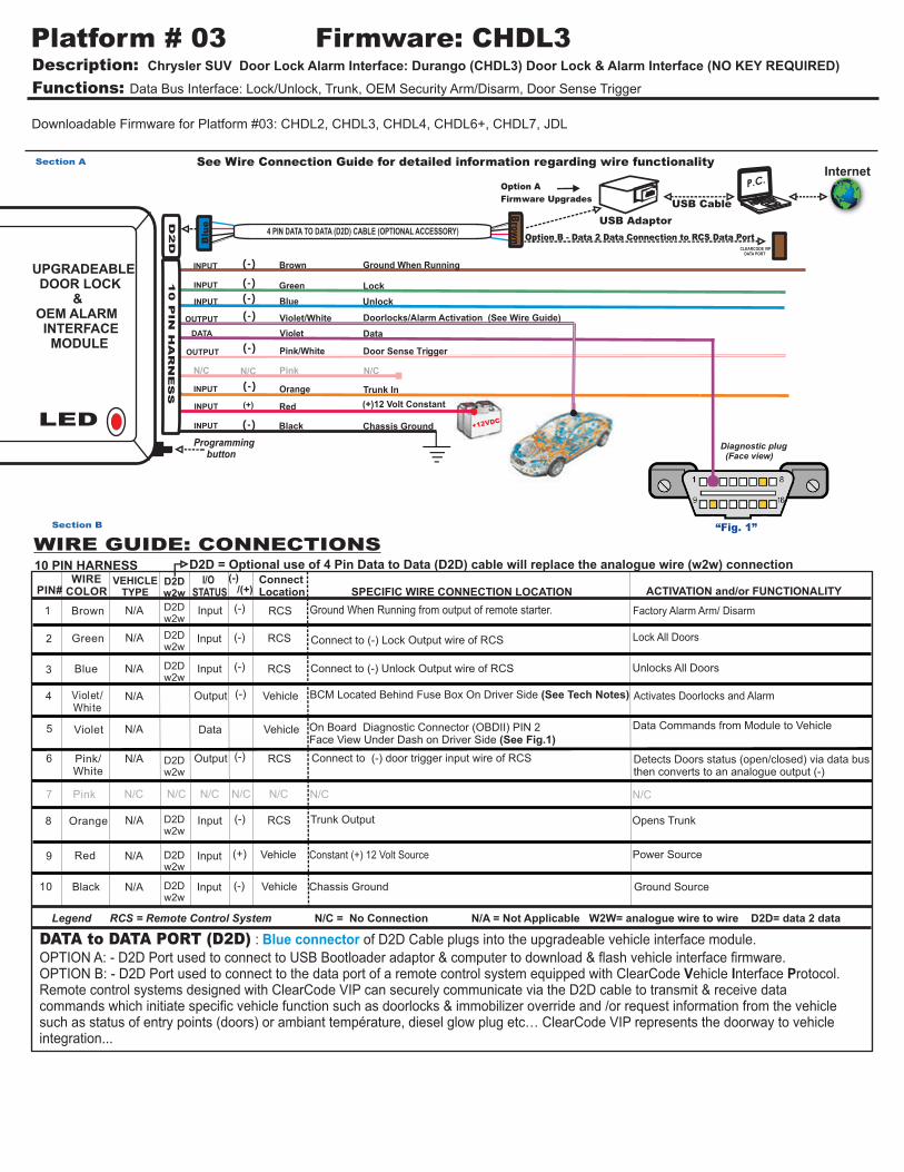
Description: Chrysler SUV Door Lock Alarm Interface: Durango (CHDL3) Door Lock & Alarm Interface (NO KEY REQUIRED)
Functions: Data Bus Interface: Lock/Unlock, Trunk, OEM Security Arm/Disarm, Door Sense Trigger
Platform # 03 Firmware: CHDL3
Red
Orange
Green
Blue
Violet
Black
Violet/White
Pink
Pink/White
Chassis Ground
(+)12 Volt Constant
Trunk In
N/C
Doorlocks/Alarm Activation (See Wire Guide)
Unlock
Programming button
Lock
Brown Ground When Running
D2D
INPUT
INPUT
INPUT
INPUT
INPUT
DATA
(-)
(+)
(-)
(-)
(-)
(-)
4 PIN DATA TO DATA (D2D) CABLE (OPTIONAL ACCESSORY)
(-)
(-)
Data
See Wire Connection Guide for detailed information regarding wire functionality
P.C.
USB Adaptor
USB Cable
Option A
Firmware UpgradesB
lue
Brow
n
CLEARCODE VIP DATA PORT
Legend RCS = Remote Control System N/C = No Connection N/A = Not Applicable W2W= analogue wire to wire D2D= data 2 data
(-) /(+)
(-)
VEHICLE TYPE
Input
Input
Input
Input
Input
Input
Data
(-)
WIRECOLOR
Brown
Green
Blue
Violet/White
Violet
Pink/White
Pink
Orange
Red
Black
(-)
(-)
(+)
SPECIFIC WIRE CONNECTION LOCATION
BCM Located Behind Fuse Box On Driver Side (See Tech Notes)
Trunk Output
Constant (+) 12 Volt Source
Chassis Ground
ConnectLocation
RCS
RCS
RCS
Vehicle
Vehicle
Vehicle
(-)
ACTIVATION and/or FUNCTIONALITY
Factory Alarm Arm/ Disarm
Lock All Doors
Unlocks All Doors
Opens Trunk
RCSN/A
N/A
N/A
N/A
N/A
N/A
N/C
N/A
N/A
N/A
Power Source
Ground Source
WIRE GUIDE: CONNECTIONS
Section B
Ground When Running from output of remote starter.
DATA to DATA PORT (D2D) : of D2D Cable plugs into the upgradeable vehicle interface module. OPTION A: - D2D Port used to connect to USB Bootloader adaptor & computer to download & flash vehicle interface firmware.OPTION B: - D2D Port used to connect to the data port of a remote control system equipped with ClearCode Vehicle Interface Protocol.Remote control systems designed with ClearCode VIP can securely communicate via the D2D cable to transmit & receive data commands which initiate specific vehicle function such as doorlocks & immobilizer override and /or request information from the vehicle such as status of entry points (doors) or ambiant température, diesel glow plug etc… ClearCode VIP represents the doorway to vehicle integration...
Blue connector
Internet
10 PIN HARNESS I/O STATUS
D2Dw2w
On Board Diagnostic Connector (OBDII) PIN 2Face View Under Dash on Driver Side (See Fig.1)
Data Commands from Module to Vehicle
Detects Doors status (open/closed) via data bus then converts to an analogue output (-)
Connect to (-) door trigger input wire of RCS
Connect to (-) Unlock Output wire of RCS
Connect to (-) Lock Output wire of RCS
Option B - Data 2 Data Connection to RCS Data Port
Door Sense Trigger
+12VDC
10 P
IN
HA
RN
ES
S
LED
UPGRADEABLE DOOR LOCK & OEM ALARM INTERFACE MODULE
D2D = Optional use of 4 Pin Data to Data (D2D) cable will replace the analogue wire (w2w) connection
D2Dw2w
D2Dw2w
D2Dw2w
D2Dw2w
D2Dw2w
D2Dw2w
D2Dw2w
N/C
Description: Chrysler SUV Door Lock Alarm Interface: Durango (CHDL3) Door Lock & Alarm Interface (NO KEY REQUIRED)
Functions: Data Bus Interface: Lock/Unlock, Trunk, OEM Security Arm/Disarm
Platform # 03 Firmware: CHDL3
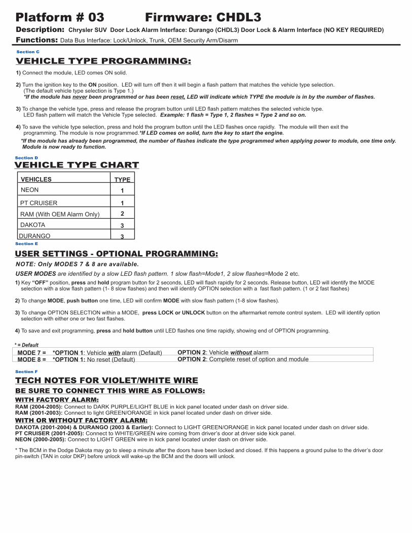
VEHICLE TYPE CHART
1) Connect the module, LED comes ON solid. 2) Turn the ignition key to the ON position. LED will turn off then it will begin a flash pattern that matches the vehicle type selection. (The default vehicle type selection is Type 1.) *If the module has never been programmed or has been reset, LED will indicate which TYPE the module is in by the number of flashes.
3) To change the vehicle type, press and release the program button until LED flash pattern matches the selected vehicle type. LED flash pattern will match the Vehicle Type selected. Example: 1 flash = Type 1, 2 flashes = Type 2 and so on.
4) To save the vehicle type selection, press and hold the program button until the LED flashes once rapidly. The module will then exit the programming. The module is now programmed.*If LED comes on solid, turn the key to start the engine.
VEHICLE TYPE PROGRAMMING:
Section C
*If the module has already been programmed, the number of flashes indicate the type programmed when applying power to module, one time only. Module is now ready to function.
MODE 7 = MODE 8 = *OPTION 1: No reset (Default)
*OPTION 1: Vehicle with alarm (Default) OPTION 2: Vehicle without alarmOPTION 2: Complete reset of option and module
* = Default
USER SETTINGS - OPTIONAL PROGRAMMING:
USER MODES are identified by a slow LED flash pattern. 1 slow flash=Mode1, 2 slow flashes=Mode 2 etc.
Section E
NOTE: Only MODES 7 & 8 are available.
1) Key “OFF” position, press and hold program button for 2 seconds, LED will flash rapidly for 2 seconds. Release button, LED will identify the MODE selection with a slow flash pattern (1- 8 slow flashes) and then will identify OPTION selection with a fast flash pattern. (1 or 2 fast flashes)
2) To change MODE, push button one time, LED will confirm MODE with slow flash pattern (1-8 slow flashes).
3) To change OPTION SELECTION within a MODE, press LOCK or UNLOCK button on the aftermarket remote control system. LED will identify option selection with either one or two fast flashes. 4) To save and exit programming, press and hold button until LED flashes one time rapidly, showing end of OPTION programming.
Section D
Section F
TECH NOTES FOR VIOLET/WHITE WIREBE SURE TO CONNECT THIS WIRE AS FOLLOWS:
WITH FACTORY ALARM:RAM (2004-2005): Connect to DARK PURPLE/LIGHT BLUE in kick panel located under dash on driver side.RAM (2001-2003): Connect to light GREEN/ORANGE in kick panel located under dash on driver side.
WITH OR WITHOUT FACTORY ALARM:DAKOTA (2001-2004) & DURANGO (2003 & Earlier): Connect to LIGHT GREEN/ORANGE in kick panel located under dash on driver side.PT CRUISER (2001-2005): Connect to WHITE/GREEN wire coming from driver’s door at driver side kick panel.NEON (2000-2005): Connect to LIGHT GREEN wire in kick panel located under dash on driver side.
* The BCM in the Dodge Dakota may go to sleep a minute after the doors have been locked and closed. If this happens a ground pulse to the driver’s door pin-switch (TAN in color DKP) before unlock will wake-up the BCM and the doors will unlock.
VEHICLES TYPE
NEON
PT CRUISER
RAM (With OEM Alarm Only)
1
1
2
DAKOTA
DURANGO
3
3
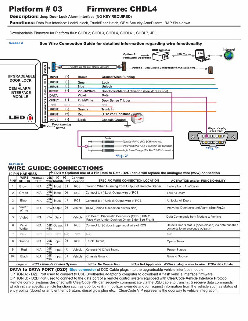
Description: Jeep Door Lock Alarm Interface (NO KEY REQUIRED)
Functions: Data Bus Interface: Lock/Unlock, Trunk/Rear Hatch, OEM Security Arm/Disarm, RAP Shut-down.
Violet/White Doorlocks/Alarm Activation (See Wire Guide)OUTPUT (-)
Violet DATA Data
P.C.
Red (+)12 Volt ConstantINPUT (+)
See Wire Connection Guide for detailed information regarding wire functionality
Option A
Firmware Upgrades
USB Adaptor
USB Cable
4 PIN DATA TO DATA (D2D) CABLE (OPTIONAL ACCESSORY)
Blu
e
Brow
n
Section A
D2D
Programming button
“Fig. 1”
Diagnostic plug (Face view)
N/C
Legend RCS = Remote Control System N/C = No Connection N/A = Not Applicable W2W= analogue wire to wire D2D= data 2 data
(-) /(+)
(-)
VEHICLE TYPE
Input
Input
Input
Input
Input
Input
Data
(-)
WIRECOLOR
Brown
Green
Blue
Violet/White
Violet
Pink/White
Pink
Orange
Red
Black
(-)
(-)
(+)
SPECIFIC WIRE CONNECTION LOCATION
Trunk Output
Constant (+) 12 Volt Source
Chassis Ground
ConnectLocation
RCS
RCS
RCS
Vehicle
Vehicle
Vehicle
(-)
ACTIVATION and/or FUNCTIONALITY
Factory Alarm Arm/ Disarm
Lock All Doors
Unlocks All Doors
Opens Trunk
RCSN/A
N/A
N/A
N/A
N/A
N/A
N/A
N/A
N/A
Power Source
Ground Source
WIRE GUIDE: CONNECTIONS Section B
Ground When Running from Output of Remote Starter.
PIN#
1
2
3
4
5
6
7
8
9
10
Output (-) RCS
N/CN/C N/C N/C N/C N/C
Activates Doorlocks and Alarm (See Fig.2)BCM (Behind fusebox on drivers side) Vehicle(-)Output
OUTPUT
D2D
DATA to DATA PORT (D2D): of D2D Cable plugs into the upgradeable vehicle interface module. OPTION A: - D2D Port used to connect to USB Bootloader adaptor & computer to download & flash vehicle interface firmware.OPTION B: - D2D Port used to connect to the data port of a remote control system equipped with ClearCode Vehicle Interface Protocol.Remote control systems designed with ClearCode VIP can securely communicate via the D2D cable to transmit & receive data commands which initiate specific vehicle function such as doorlocks & immobilizer override and /or request information from the vehicle such as status of entry points (doors) or ambient température, diesel glow plug etc… ClearCode VIP represents the doorway to vehicle integration...
Blue connector
I/O STATUS
D2Dw2w
N/C
10 PIN HARNESS
On Board Diagnostic Connector (OBDII) PIN 2Face View Under Dash on Driver Side (See Fig.1)
Data Commands from Module to Vehicle
Detects Doors status (open/closed) via data bus then converts to an analogue output (-)
Internet
Diode
Pink/Violet (PIN 10) of C2 junction box connector.
Light Green/Orange (PIN 9) of C2 BCM connector.
Tan wire (PIN 4) of C1 BCM connector.
“Fig. 2”
Connect to (-) door trigger input wire of RCS
Connect to (-) Lock Output wire of RCS
Connect to (-) Unlock Output wire of RCS
Option B - Data 2 Data Connection to RCS Data Port
Door Sense Trigger
LED
UPGRADEABLE DOOR LOCK & OEM ALARM INTERFACE MODULE
+12VDC
D2Dw2w
D2Dw2w
D2Dw2w
D2Dw2w
D2Dw2w
D2Dw2w
D2Dw2w
w2w
w2w
D2D = Optional use of 4 Pin Data to Data (D2D) cable will replace the analogue wire (w2w) connection
10 P
IN
H
AR
NE
SS
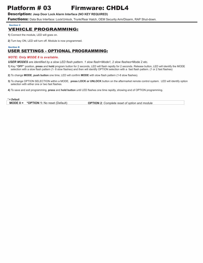
Description: Jeep Door Lock Alarm Interface (NO KEY REQUIRED)
Functions: Data Bus Interface: Lock/Unlock, Trunk/Rear Hatch, OEM Security Arm/Disarm, RAP Shut-down.
Platform # 03 Firmware: CHDL4
VEHICLE PROGRAMMING:
1) Connect the module, LED will goes on.
2) Turn key ON, LED will turn off. Module is now programmed.
Section C
MODE 8 = *OPTION 1: No reset (Default) OPTION 2: Complete reset of option and module
* = Default
USER SETTINGS - OPTIONAL PROGRAMMING:
USER MODES are identified by a slow LED flash pattern. 1 slow flash=Mode1, 2 slow flashes=Mode 2 etc.
Section D
NOTE: Only MODE 8 is available.
1) Key “OFF” position, press and hold program button for 2 seconds, LED will flash rapidly for 2 seconds. Release button, LED will identify the MODE selection with a slow flash pattern (1- 8 slow flashes) and then will identify OPTION selection with a fast flash pattern. (1 or 2 fast flashes)
2) To change MODE, push button one time, LED will confirm MODE with slow flash pattern (1-8 slow flashes).
3) To change OPTION SELECTION within a MODE, press LOCK or UNLOCK button on the aftermarket remote control system. LED will identify option selection with either one or two fast flashes. 4) To save and exit programming, press and hold button until LED flashes one time rapidly, showing end of OPTION programming.
+12VDC
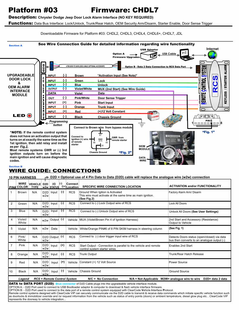
Description: Chrysler Dodge Jeep Door Lock Alarm Interface (NO KEY REQUIRED)
Functions: Data Bus Interface: Lock/Unlock, Trunk/Rear Hatch, OEM Security Arm/Disarm, Starter Enable, Door Sense Trigger
Violet/White MUX (2nd Start) (See Wire Guide) OUTPUT (-)
Violet DATA Data
P.C.
Red (+)12 Volt ConstantINPUT (+)
Platform #03 Firmware: CHDL7
See Wire Connection Guide for detailed information regarding wire functionality
Option A
Firmware Upgrades
USB Adaptor
USB Cable
4 PIN DATA TO DATA (D2D) CABLE (OPTIONAL ACCESSORY)
Blu
e
Brow
n
Section A
D2D
Programming button
WIRE GUIDE: CONNECTIONS Section B
“Fig. 1”
86PIN
1
87
87A
30
8586
“Fig. 2”
Connect to ignition (+) wire of remotestarter
Connect to Brown wire from bypass module.
Chassis Ground
GWR from remote starter
*NOTE: If the remote control system does not have an activation output that turns on at exactly the same time as the 1st ignition, then add relay and install as per Fig.2.Most remote systems GWR or (-) 3rd ignition outputs turn on before the main ignition and will cause diagnostic codes.
D2D
RC
SEM
OTE
ONTR
OL Y
STEM
KE
YLE
SS
/ S
TAR
TE
R/ A
LAR
M
RC
S
DATA WIRE
SKIM MODULE
Internet
Legend RCS = Remote Control System N/C = No Connection N/A = Not Applicable W2W= analogue wire to wire D2D= data 2 data
(-) /(+)
(-)
VEHICLE TYPE
Input
Input
Input
Input
Input
Input
Input
Output
Output
Data
(-)
(-)
WIRECOLOR
Brown
Green
Blue
Violet/White
Violet
Pink/White
Pink
Orange
Red
Black
(-)
(-)
(-)
(+)
SPECIFIC WIRE CONNECTION LOCATION
MUX (Violet/Brown Pin 4 of Ignition Harness)
Trunk Output
Constant (+) 12 Volt Source
Chassis Ground
ConnectLocation
Vehicle
RCS
RCS
RCS
RCS
Vehicle
Vehicle
Vehicle
(-)
ACTIVATION and/or FUNCTIONALITY
Factory Alarm Arm/ Disarm
Lock All Doors
Unlock All Doors (See User Settings)
2nd Start and Accessory (Resistance) Output to Vehicle
Enables 2nd Start
Trunk/Rear Hatch Release
RCS
Start Output - Connection is parallel to the vehicle and remote control system starter wires.
N/A
N/A
N/A
N/A
N/A
N/A
N/A
N/A
N/A
N/A
(See Fig. 1)
(+) RCS
Power Source
Ground Source
I/O STATUSPIN#
1
2
3
4
5
6
7
8
9
10
D2Dw2w
Detects Doors status (open/closed) via data bus then converts to an analogue output (-)
White/Orange PIN#6 of 8 PIN SKIM harness in steering column
10 PIN HARNESS
DATA to DATA PORT (D2D): of D2D Cable plugs into the upgradeable vehicle interface module.
OPTION A: - D2D Port used to connect to USB Bootloader adaptor & computer to download & flash vehicle interface firmware.OPTION B: - D2D Port used to connect to the data port of a remote control system equipped with ClearCode Vehicle Interface Protocol.Remote control systems designed with ClearCode VIP can securely communicate via the D2D cable to transmit & receive data commands which initiate specific vehicle function such as doorlocks & immobilizer override and /or request information from the vehicle such as status of entry points (doors) or ambient température, diesel glow plug etc…ClearCode VIP represents the doorway to vehicle integration...
Blue connector
Ground When Igition is ActivatedThis wire must activate at the same time as main ignition. (See Fig.2)
Connect to (-) door trigger input wire of RCS
Connect to (-) Lock Output wire of RCS
Connect to (-) Unlock Output wire of RCS
D2D = Optional use of 4 Pin Data to Data (D2D) cable will replace the analogue wire (w2w) connection
D2Dw2w
D2Dw2w
D2Dw2w
D2Dw2w
D2Dw2w
D2Dw2w
D2Dw2w
D2Dw2w
w2w
w2w
10 P
IN
H
AR
NE
SSLED
UPGRADEABLE DOOR LOCK & OEM ALARM INTERFACE MODULE
Option B - Data 2 Data Connection to RCS Data Port
Section C
1) Connect the module, LED comes ON solid. 2) Turn key to ON position. LED will turn OFF. Module is now programmed.
VEHICLE PROGRAMMING:
MODE 1 = MODE 8 = *OPTION 1: No reset (Default)
*OPTION 1: 1st pulse unlock all doors (Default) OPTION 2: 1st pulse unlock driver door, 2nd pulse unlock all doors OPTION 2: Complete reset of option and module
* = Default
USER SETTINGS - OPTIONAL PROGRAMMING:
USER MODES are identified by a slow LED flash pattern. 1 slow flash=Mode1, 2 slow flashes=Mode 2 etc.
Section D
NOTE: Only MODES 1 & 8 are available.
1) Key “OFF” position, press and hold program button for 2 seconds, LED will flash rapidly for 2 seconds. Release button, LED will identify the MODE selection with a slow flash pattern (1- 8 slow flashes) and then will identify OPTION selection with a fast flash pattern. (1 or 2 fast flashes)
2) To change MODE, push button one time, LED will confirm MODE with slow flash pattern (1-8 slow flashes).
3) To change OPTION SELECTION within a MODE, press LOCK or UNLOCK button on the aftermarket remote control system. LED will identify option selection with either one or two fast flashes.
4) To save and exit programming, press and hold button until LED flashes one time rapidly, showing end of OPTION programming.
Description: Chrysler Dodge Jeep Door Lock Alarm Interface (NO KEY REQUIRED)
Functions: Data Bus Interface: Lock/Unlock, Trunk/Rear Hatch, OEM Security Arm/Disarm, Starter Enable, Door Sense Trigger
Platform #03 Firmware: CHDL7
Description: Chrysler Dodge Jeep Door Lock Alarm Interface (NO KEY REQUIRED)
Functions: Data Bus Interface: Lock/Unlock, Trunk/Rear Hatch, OEM Security Arm/Disarm, Starter Enable, Door Sense Trigger
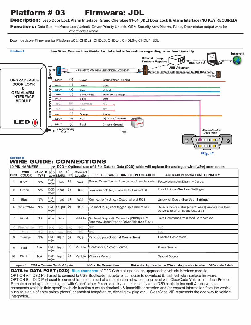
On Board Diagnostic Connector (OBDII) PIN 2Face View Under Dash on Driver Side (See Fig.1)
RCS
N/C N/C N/C N/C N/C
Section A
Door Sense Trigger
N/CN/CN/C
Panic
(-)Output
N/A
N/C N/C N/C N/C
Enables Panic Mode
N/C N/C
OUTPUT
Detects Doors status (open/closed) via data bus then converts to an analogue output (-)
I/O STATUS
D2Dw2w
10 PIN HARNESS
DATA to DATA PORT (D2D): of D2D Cable plugs into the upgradeable vehicle interface module. OPTION A: - D2D Port used to connect to USB Bootloader adaptor & computer to download & flash vehicle interface firmware.OPTION B: - D2D Port used to connect to the data port of a remote control system equipped with ClearCode Vehicle Interface Protocol.Remote control systems designed with ClearCode VIP can securely communicate via the D2D cable to transmit & receive data commands which initiate specific vehicle function such as doorlocks & immobilizer override and /or request information from the vehicle such as status of entry points (doors) or ambient température, diesel glow plug etc… ClearCode VIP represents the doorway to vehicle integration...
Blue connector
Data Commands from Module to Vehicle
D2Dw2w
N/C
N/C
Internet
(-) Orange INPUT
Input (-) RCS
Constant (+) 12 Volt Source
Panic Output (Optional Connection)
Connect to (-) door trigger input wire of RCS
Connect to (-) Unlock Output wire of RCS
Option B - Data 2 Data Connection to RCS Data Port
10 P
IN
H
AR
NE
SS
D2D = Optional use of 4 Pin Data to Data (D2D) cable will replace the analogue wire (w2w) connection
D2Dw2w
D2Dw2w
D2Dw2w
D2Dw2w
D2Dw2w
D2Dw2w
w2w
LED
UPGRADEABLE DOOR LOCK & OEM ALARM INTERFACE MODULE
1) Connect the module, LED comes ON solid. 2) Turn the ignition key to the ON position. LED will turn off. Module is now programmed.
VEHICLE PROGRAMMING:
MODE 1 = *OPTION 1: 1st pulse unlock all doorsMODE 5 = *OPTION 1: Windows roll-up OFFMODE 8 = OPTION 1: Reset mode with unlock button
OPTION 2: 1st pulse unlock driver door, 2nd pulse unlock all doorOPTION 2: Windows roll-up ON
* = Default
Section C
Description: Jeep Door Lock Alarm Interface: Grand Cherokee 99-04 (JDL) Door Lock & Alarm Interface (NO KEY REQUIRED)
Functions: Data Bus Interface: Lock/Unlock, Driver Priority Unlock, OEM Security Arm/Disarm, Panic, Door status output wire for
aftermarket alarm
Platform # 03 Firmware: JDL
USER SETTINGS - OPTIONAL PROGRAMMING: USER MODES are identified by a slow LED flash pattern. 1 slow flash=Mode1, 2 slow flashes=Mode 2 etc.
Section D
1) Key “OFF” position, press and hold program button for 2 seconds, LED will flash rapidly for 2 seconds. Release button, LED will identify the MODE selection with a slow flash pattern (1- 8 slow flashes) and then will identify OPTION selection with a fast flash pattern. (1 or 2 fast flashes)
2) To change MODE, push button one time, LED will confirm MODE with slow flash pattern (1-8 slow flashes).
3) To change OPTION SELECTION within a MODE, press LOCK or UNLOCK button on the aftermarket remote control system. LED will identify option selection with either one or two fast flashes. 4) To save and exit programming, press and hold button until LED flashes one time rapidly, showing end of OPTION programming.
*If module has already been programmed , LED will flash 4 times.