108


Please note:As a result of more stringent legal regulations and judgements regarding product liability, we areobliged to point out certain risks that may arisewhen products are used under extraordinaryoperating conditions.
The mechanical design is based on the environmentalconditions as stipulated in ETS 300 019-1-4, whichinclude the static mechanical load imposed on anantenna by wind at maximum velocity.
Extraordinary operating conditions, such as heavy icing or exceptional dynamic stress (e.g. strain causedby oscillating support structures), may result in thebreakage of an antenna or even cause it to fall to the ground.
These facts must be considered during the site planningprocess.
The details given in our data sheets have to befollowed carefully when installing the antennas andaccessories.In addition, please use our information brochureabout mounting configurations.
The installation team must be properly qualified and also be familiar with the relevant national safetyregulations.
Photo on title page: Flight survaliance on “Koralpe (Austria)”
Catalogue Issue 11/2007
All data published in previous catalog issues hereby becomes invalid.We reserve the right to make alterations in accordance with the requirements of our customers, therefore for binding datas please check valid datasheets!
KATHREIN-Werke KG . Phone +49 8031 184-0 . Fax +49 8031 184-494Anton-Kathrein-Straße 1 – 3 . P.O. Box 10 04 44 . D-83004 Rosenheim . Germany
Internet: http://www.kathrein.de
“Quality leads the way”As the world’s oldest and largest antenna manufacturer, we live up to claim “Qualityleads the way” on a daily basis. One of the fundamental principies is to always be onthe lookout for the best solution for our customers.
Our quality assurance system and our environmental management system apply to theentire company and are certified by TÜV according to EN ISO 9001 and EN ISO 14001.
3
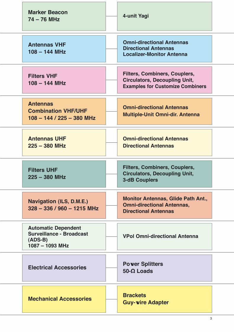
Marker Beacon74 – 76 MHz
Antennas VHF108 – 144 MHz
Filters VHF108 – 144 MHz
AntennasCombination VHF/UHF108 – 144 / 225 – 380 MHz
Antennas UHF225 – 380 MHz
Filters UHF225 – 380 MHz
Navigation (ILS, D.M.E.)328 – 336 / 960 – 1215 MHz
Automatic DependentSurveillance - Broadcast(ADS-B)1087 – 1093 MHz
Electrical Accessories
Mechanical Accessories
4-unit Yagi
Omni-directional AntennasDirectional AntennasLocalizer-Monitor Antenna
Filters, Combiners, Couplers,Circulators, Decoupling Unit,Examples for Customize Combiners
Omni-directional AntennasMultiple-Unit Omni-dir. Antenna
Omni-directional AntennasDirectional Antennas
Filters, Combiners, Couplers,Circulators, Decoupling Unit,3-dB Couplers
Monitor Antennas, Glide Path Ant.,Omni-directional Antennas, Directional Antennas
VPol Omni-directional Antenna
Power Splitters50-Ω Loads
BracketsGuy-wire Adapter

4
Summary of Types
The articles are listed by type number in numerical order.
729 ...
729 803 16, 17
741 ...
741 495 90, 91
742 ...
742 363 107
780 ...
780 231 79
780 265 50
780 266 51
784 ...
784 10025 47
784 10198 43
784 10367 102
784 10470 102
791 ...
791 211 45
791 525 42
791 526 42
791 527 42
791 528 49
791 653 48
791 857 44
791 859 44
791 988 75
792 ...
792 008 76
792 246 77
792 318 44
792 329 44
792 330 44
792 504 42
792 558 42
792 863 52
792 865 52
792 868 52
792 871 52
793 ...
793 094 45
800 ...
800 10228 6
880 ...
880 10002 96, 97
K 51 ...
K 51 26 31 8, 9
K 52 ...
K 52 30 31 28, 29
K 52 31 31 26, 27
K 52 31 37 26, 27
K 53 ...
K 53 18 31 22, 23
K 55 ...
K 55 20 31 14, 15
K 55 21 31 12, 13
K 55 31 31 24, 25
K 55 32 31 30, 31
K 61 ...
K 61 33 3 106
K 61 33 4 106
K 62 ...
K 62 26 11 1 102
K 62 26 20 1 103
K 62 26 20 7 103
K 62 26 21 1 103
K 62 26 21 7 103
K 62 26 30 1 103
K 62 26 30 7 103
K 62 26 31 1 103
Type No. Page Type No. Page Type No. Page Type No. Page
711 ...
711 329 20, 21
713 ...
713 316 B 86, 87
713 645 106
714 ...
714 747 84, 85
715 ...
715 279 90, 91
715 630 82, 83
715 986 88, 89
716 ...
716 192 106
716 405 92, 93
717 ...
717 265 18, 19
717 266 18, 19
717 338 56, 57
718 ...
718 215 10, 11
718 217 62, 63
719 ...
719 543 18, 19
719 557 16, 17
722 ...
722 394 88, 89
723 ...
723 141 66, 67
723 904 58, 59
727 ...
727 463 16, 17
727 728 56, 57
K 62 26 31 7 103
K 62 26 40 1 103
K 62 26 41 1 103
K 62 26 50 1 103
K 62 26 50 7 103
K 62 26 51 1 103
K 62 26 61 1 102
K 62 55 31 100, 101
K 62 56 3 100, 101
K 62 56 31 100, 101
K 62 57 3 100, 101
K 62 57 31 100, 101
K 62 70 31 46
K 63 ...
K 63 55 11 100, 101
K 63 70 11 78
K 64 ...
K 64 12 31 36, 37
K 64 13 31 36, 37
K 64 21 35 1 34, 35
K 64 21 36 1 38, 39
K 64 21 37 1 38, 39
K 64 31 31 40, 41
K 64 32 31 40, 41
K 64 33 31 40, 41
K 65 ...
K 65 13 11 74
K 75 ...
K 75 10 11 64, 65
K 75 31 11 68, 69
K 75 32 11 70, 71
K 75 40 12 1 66, 67
K 75 40 13 1 66, 67
K 75 40 14 1 66, 67
K 75 40 15 1 66, 67
New Products

5
Summary - Marker Beacon74 – 76 MHz
Type Frequency Gain Type No. Height Pagerange [mm]
Yagi Antenna4-unit Yagi Antenna 74 – 76 MHz 125° 7 dBi 800 10228 1980 6
Mar
ker
Bea
con
74 –
76
MH
z
New Products
6
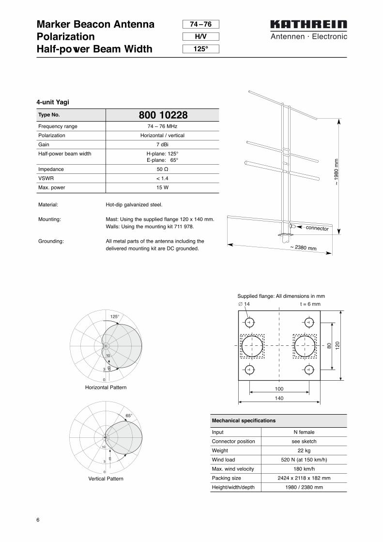
800 10228Frequency range 74 – 76 MHz
Polarization Horizontal / vertical
Gain 7 dBi
Half-power beam width H-plane: 125°E-plane: 65°
Impedance 50 Ω
VSWR < 1.4
Max. power 15 W
Type No.
Material: Hot-dip galvanized steel.
Mounting: Mast: Using the supplied flange 120 x 140 mm.Walls: Using the mounting kit 711 978.
Grounding: All metal parts of the antenna including thedelivered mounting kit are DC grounded.
Marker Beacon AntennaPolarizationHalf-power Beam Width
~ 1
980
mm
~ 2380 mm
74 –76
H/V
125°
Input N female
Connector position see sketch
Weight 22 kg
Wind load 520 N (at 150 km/h)
Max. wind velocity 180 km/h
Packing size 2424 x 2118 x 182 mm
Height/width/depth 1980 / 2380 mm
Mechanical specifications
3 dB
10
0
125°
65°
dB
10
3
0
Horizontal Pattern
Vertical Pattern
4-unit Yagi
connector
100
140
80 120
∅ 14 t = 6 mm
Supplied flange: All dimensions in mm

7
Type Frequency Gain Connector Type No. Height Pagerange [mm]
Omnidirectional Antennas
Omni 116 – 152 MHz 360° 0 dB N-female K 51 26 31 430 8, 9
Omni 118 – 137 MHz 360° 0 dB 7-16 female 718 215 1050 10, 11
Omni 108 – 152 MHz 360° 0 dB N-female K 55 21 31 1300 12, 13
Omni 118 – 137 MHz 360° 0 dB N-female K 55 20 31 1375 14, 15
Omni 118 – 137 MHz 360° 0.5 dB N-female 727 463 4300 16, 17
Omni 116 – 152 MHz 360° 0 dB N-female 719 557 4800 16, 17
Omni 118 – 137 MHz 360° 0.5 dB N-female 729 803 6000 16, 17
Omni 116 – 152 MHz 360° 3 dB N-female 719 543 4600 18, 19
Omni 118 – 137 MHz 360° 3.5 dB N-female 717 265 4000 18, 19
Omni 118 – 137 MHz 360° 4.5 dB N-female 717 266 6000 18, 19
Localizer-Monitor
Directional Antenna 108 – 118 MHz 112° 5 dB N-female 711 329 1105 20, 21
Directional Antennas
Directional Antenna 118 – 144 MHz 120° 4 dB N-female K 53 18 31 1360 22, 23
Directional Antenna 118 – 136 MHz Approx. 240° 5 dB N-female K 55 31 31 2940 24, 25
Directional Antenna 108 – 137 MHz 76° 7 dB N-female K 52 31 31 1600 26, 27
Directional Antenna 108 – 137 MHz 76° 7 dB 7-16 female K 52 31 37 1600 26, 27
Directional Antenna 100 – 160 MHz 62° 8 dB N-female K 52 30 31 1900 28, 29
Directional Antenna 118 – 144 MHz Approx. 240° 8 dB N-female K 55 32 31 6040 30, 31
Summary - Antennas VHF108 – 144 MHz
Omnidirectional Antennas
New Products
An
ten
nas
VH
F10
8 –
144
MH
z

8
Omnidirectional Antenna116 – 152 MHzK 51 26 31
Type No. K 51 26 31Input N female connector in the antenna baseConnector position BottomFrequency range 116 – 152 MHzBandwidth 36 MHzVSWR < 1.6 (118 – 144 MHz)
< 2.0 (116 – 152 MHz)Gain 0 dB (ref. to the half wave dipole)Impedance 50 ΩPolarization VerticalMax. power 60 W (at 50 °C ambient temperature)Weight 1.5 kgWind load 50 N (at 160 km/h)Max. wind velocity
w/o ice 200 km/h1/2″ radial ice 135 km/h
Packing size 100 x 85 x 720 mmHeight L1: 430 mm, L2: 700 mm
Material: Radiator: Heavy duty alodined aluminum.Radials: Stainless steel 8 mm diameter. Base: High strength cast aluminum. All screws and nuts: Stainless steel.
Mounting: The antenna can be mounting by means of a supplied stainless steel clamp in such a manner as to permit the cable to be run either inside a 40 – 54 mm pipe (Fig. A) or outside a 20 – 54 mm pipe (Fig. B).
Grounding: The antenna is DC grounded by a cross sectionof 120 mm2 aluminum.
Scope of supply: Antenna including mounting hardware.
Broadband aluminium groundplane-antenna with stainless steel radials
dB
78°
10
3
0
Radiation Pattern (at mid-band)
Vertical Pattern
3 dB
10
0
Horizonal Pattern
L 1
L 2
A
B

9
Mounting InstructionOmnidirectional AntennaK 51 26 31
Side mounting on a mast
Brackets for pipes of 55 to 105 mm OD are availabe forthis mounting mode:
Distance betweenpipe and antenna 500 mm 1000 mm
Model No. K 61 33 3 K 61 33 4
With this mounting mode the standing wave ratio (VSWR)will be altered somewhat as a factor of clearance and mastdiameter.
A
B
A: For pipes of 40 – 54 mm diameterB: For pipes of 20 – 54 mm diameter

10
Omnidirectional Antenna718 215118 – 137 MHz
● VHF 4-unit omnidirectional antenna.● Each unit consists of 4 dipoles round the mast (diameter
200 – 600 mm), which are combined by an integrated powersplitter.
Type No. 718 215Input 7 -16 female
Frequency range 118 – 137 MHz
Gain (ref. λ/2 dipole) 0 dB
VSWR < 1.5
Horizontal radiation pattern:Deviation from circularity ±1.5 dB
Impedance 50 Ω
Polarisation Vertical
Max. power 400 W (at 50 °C ambient temperature)
Length 1050 mm
Weight 32 kg (for a mast of 500 mm dia.)
Wind load 2.5 kN (at 180 km/h and 4 cm radial ice)
Material: – Hot dip galvanized steel.
Mounting: – On a pipe mast with a dia. of 200 – 600 mm.Please specify exact dia. with order.The cable length needs to stay unchanged!
Grounding: – All metal parts of the antenna including thedelivered mounting kit are DC grounded.
Scope of supply: – Antenna incl. power splitter, cable and mounting clamps (pipe mast not supplied).

11
mast diameter > 200 mm,clamps (supplied):
clamp range 200 – 400 mm (order-no. 131 1484) and clamp range 400 – 600 mm (order-no. 131 1485)
7-16 female
Omnidirectional Antenna718 215118 – 137 MHz
approx. 435 mm
appr
ox.
1050
mm
appr
ox.
920
mm

12
Omnidirectional Antenna108 – 152 MHzK 55 21 31
Type No. K 55 21 31Input N female connector in the antenna baseConnector position BottomFrequency range 108 – 152 MHzBandwidth 44 MHzVSWR < 2.0Gain 0 dB (ref. to the half wave dipole)Impedance 50 ΩPolarization VerticalMax. power 110 W (at 50 °C ambient temperature)Weight 5.2 kgRadome diameter 120 mmWind load 120 N (at 160 km/h)Max. wind velocity 200 km/h (incl. 1/ 2˝ radial ice)Packing size 650 x 130 x 100 mmHeight Approx. 1300 mm
Material: Aluminum radiator in fiberglass radome. Colour: Grey RAL 7001. Hot dip galvanized steel bottom. All screws and nuts: Stainless steel.
Mounting: By means of 4 studs M12 to flange 130 mm dia.
Grounding: The antenna is DC grounded by a cross sectionof 26 mm2 aluminum.
Scope of supply: Antenna including 1 neoprene O-ring and 4 mounting studs, each with 2 nuts and 1 washer.
Broadband omnidirectional antennain fiberglass radome
dB
78°
10
3
0
Radiation Pattern (at mid-band)
Vertical Pattern
3 dB
10
0
Horizonal Pattern
≈13
00 m
m
120 mmdiameter

13
Mounting InstructionOmnidirectional AntennaK 55 21 31
M 12 x 35
100 mm
130 mm
flange 130 mm ∅required metric wrenches:19 mm
14
Omnidirectional Antenna118 – 137 MHzK 55 20 31
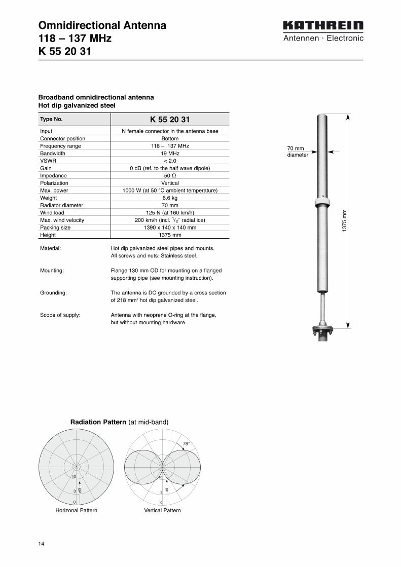
Type No. K 55 20 31Input N female connector in the antenna baseConnector position BottomFrequency range 118 – 137 MHzBandwidth 19 MHzVSWR < 2.0Gain 0 dB (ref. to the half wave dipole)Impedance 50 ΩPolarization VerticalMax. power 1000 W (at 50 °C ambient temperature)Weight 6.6 kgRadiator diameter 70 mmWind load 125 N (at 160 km/h)Max. wind velocity 200 km/h (incl. 1/ 2˝ radial ice)Packing size 1390 x 140 x 140 mmHeight 1375 mm
Material: Hot dip galvanized steel pipes and mounts. All screws and nuts: Stainless steel.
Mounting: Flange 130 mm OD for mounting on a flangedsupporting pipe (see mounting instruction).
Grounding: The antenna is DC grounded by a cross sectionof 218 mm2 hot dip galvanized steel.
Scope of supply: Antenna with neoprene O-ring at the flange, but without mounting hardware.
Broadband omnidirectional antennaHot dip galvanized steel
dB
78°
10
3
0
Radiation Pattern (at mid-band)
Vertical Pattern
3 dB
10
0
Horizonal Pattern
1375
mm
70 mmdiameter

15
Mounting InstructionOmnidirectional AntennaK 55 20 31
Ø 14 mm
100 mm130 mm

16
Omnidirectional Antenna – Multiple-unit116 ... 152 MHz719 557, 727 463, 729 803
Type No. 727 463 719 557 729 803Input N female connector inside of mounting flange
No. of dipoles 2 2 3
Connector position Bottom
Frequency range 118 – 137 MHz 116 – 152 MHz 118 – 137 MHz
Bandwidth 19 MHz 36 MHz 19 MHz
VSWR < 1.8 < 2.0 < 1.8
Gain 0.5 dB 0 dB 0.5 dB(ref. to 3 pole)
Attentuation > 27 dB > 25 dBbetween adjacent dipoles
Horizontal radiation pattern Deviation from circularity ±0.3 dB for each dipole
Impedance 50 Ω
Polarization Vertical
Max. power 100 W (at 50 °C ambient temperature)
Weight 33 kg 48 kg 54 kg
Radome diameter 120 mm 188 mm 120 mm
Wind load 480 N 724 N 700 N(at 160 km/h)
Max. wind velocity 200 km/h
Height 4300 mm 4800 mm 6000 mm
2 or 3-element antenna, consisting of several independent-ly fed dipoles arranged in line
Hei
ght
dB
78°
10
3
0
Radiation Pattern (at mid-band)
Vertical Pattern
3 dB
10
0
Horizonal Pattern
Material: Radiator: Hot dip galvanized steel. Radome: Fiberglas, colour: Brown (RAL 1019).Flange: Aluminum (OD 320 mm). Hot dip galva-nized steel (OD 265 mm). All screws and nuts: Stainless steel.
Mounting: Flange 320 mm OD (719 557).Flange 265 mm OD (727 463, 729 803).
Grounding: The antenna is DC grounded by a cross sectionof 214 mm2 (719 557) and 110 mm2 (727 463,729 803) hot dip galvanized steel.
Scope of supply: Antenna with neoprene O-ring at the flange, butwithout mounting hardware.

17
Mounting InstructionOmnidirectional Antenna719 557, 727 463, 729 803
– Mount the aluminum flange on plane surface only (max. unevenness 0.5 mm)
– Put the O-ring carefully into the circular groove of the flange
– Mounting screws: M16 stainless or hot dip galvanized steelMounting screws: M 16 (min. strength 5.6 accord. DIN 267)Max. torque: 50 Nm (screws should be greased with MoS2)
– Put a stainless steel washer between aluminum flange and screw head or nut
280 mm
320 mm
18 mm
225 mm
265 mm
18 mm
727 463729 803 719 557
18
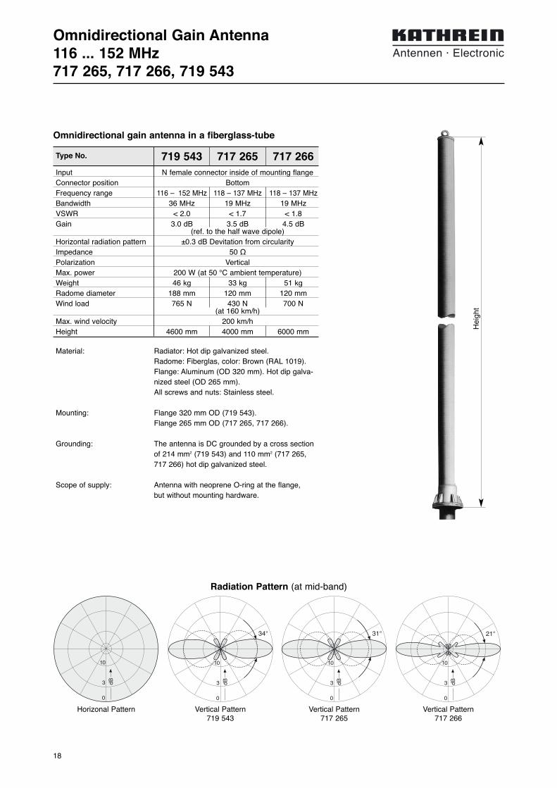
Omnidirectional Gain Antenna116 ... 152 MHz717 265, 717 266, 719 543
Type No. 719 543 717 265 717 266Input N female connector inside of mounting flangeConnector position BottomFrequency range 116 – 152 MHz 118 – 137 MHz 118 – 137 MHzBandwidth 36 MHz 19 MHz 19 MHzVSWR < 2.0 < 1.7 < 1.8Gain 3.0 dB 3.5 dB 4.5 dB
(ref. to the half wave dipole)Horizontal radiation pattern ±0.3 dB Devitation from circularityImpedance 50 ΩPolarization VerticalMax. power 200 W (at 50 °C ambient temperature)Weight 46 kg 33 kg 51 kgRadome diameter 188 mm 120 mm 120 mmWind load 765 N 430 N 700 N
(at 160 km/h)Max. wind velocity 200 km/hHeight 4600 mm 4000 mm 6000 mm
Material: Radiator: Hot dip galvanized steel. Radome: Fiberglas, color: Brown (RAL 1019).Flange: Aluminum (OD 320 mm). Hot dip galva-nized steel (OD 265 mm).All screws and nuts: Stainless steel.
Mounting: Flange 320 mm OD (719 543).Flange 265 mm OD (717 265, 717 266).
Grounding: The antenna is DC grounded by a cross sectionof 214 mm2 (719 543) and 110 mm2 (717 265,717 266) hot dip galvanized steel.
Scope of supply: Antenna with neoprene O-ring at the flange, but without mounting hardware.
Omnidirectional gain antenna in a fiberglass-tube
3 dB
10
0
34°
3 dB
10
0
31°
3 dB
10
0
21°
Radiation Pattern (at mid-band)
Vertical Pattern719 543
3 dB
10
0
Horizonal Pattern Vertical Pattern717 265
Vertical Pattern717 266
Hei
ght

19
Mounting InstructionOmnidirectional Gain Antenna717 265, 717 266, 719 543
– Mount the aluminum flange on plane surface only (max. unevenness 0.5 mm)
– Put the O-ring carefully into the circular groove of the flange
– Mounting screws: M16 stainless or hot dip galvanized steelMounting screws: M 16 (min. strength 5.6 accord. DIN 267)Max. torque: 50 Nm (screws should be greased with MoS2)
– Put a stainless steel washer between aluminum flange and screw head or nut
280 mm
320 mm
18 mm
225 mm
265 mm
18 mm
717 265717 266 719 543

20
≈ 1475
≈ 1105
Directional Antenna108 – 118 MHz711 329
Input N femaleFrequency range 108 – 118 MHzVSWR < 1.3Gain 5 dB (ref. to the half wave dipole)Impedance 50 ΩPolarization HorizontalFront-to-back ratio > 15 dBMax. Power 300 W (at 50 °C ambient temperature)Weight 10 kgWind load 220 N (at 150 km/h)Max. wind velocity 150 km/hPacking size 1525 x 1190 x 92 mm
Type No. 711 329
3-element broadband-yagi, 5 dB gain
Localizer-Monitor
Material: Hot dip galvanized steel.All screws and nuts: Stainless steel.
Mounting: To pipes of 60 – 125 mm diameter by means ofhot dip galvanized steel clamp, supplied.
Lightning protection: All metal parts of this antenna are DC grounded.
dB
120°
10
3
0
3 dB
10
0
64°
in E-plane in H-plane
Radiation Pattern (at mid-band)

21
Directional Antenna108 – 118 MHz711 329
N-female
Clamp range 60 – 125 mm diameter

22
Directional Antenna118 – 144 MHzK 53 18 31
Input N femaleconnector in a weather protective housing
directly at the antennaFrequency range 118 – 144 MHzVSWR < 1.5 Gain (ref. λ/2 dipole) 4 dB Impedance 50 ΩPolarization Usable for horizontal or vertical polarizationMax. Power 160 W (at 50 °C ambient temperature)Weight 10 kgWindload 250 N (at 160 km/h)Max. wind velocity 200 km/h (incl. 1/ 2˝ radial ice)Packing size 1500 x 1150 x 90 mmAntenna height 1360 mm
Type No. K 53 18 31
3-element broadband-yagi, 4dB gain, hot dip galvanized steel
dB
120°
10
3
0
3 dB
10
0
64°
in E-plane in H-plane
1360
mm
≈ 950 mm
Radiation Pattern (at mid-band)
Material: Hot dip galvanized steel.All screws and nuts: Stainless steel.
Mounting: To pipes of 60 – 115 mm OD by means of hotdip galvanized steel clamp, supplied.
Grounding: The antenna is DC grounded by a cross sectionof 256 mm2 hot dip galvanized steel.
Scope of supply: Antenna including mounting hardware.

23
Mounting InstructionDirectional AntennaK 53 18 31
2
1
1: For vertical polarization2: For horizontal polarization

24
Offset Pattern Gain Antenna118 – 136 MHzK 55 31 31
Input N femaleconnector inside of the mounting flange
Frequency range 118 – 136 MHzVSWR < 1.5 Gain (ref. λ/2 dipole) 5 dB Impedance 50 ΩPolarization VerticalMax. Power 280 W (at 50 °C ambient temperature)Weight 20 kgWindload 370 N (at 160 km/h)Max. wind velocity
w/o ice 200 km/h1/2˝ radial ice 150 km/h
Packing size 3000 x 510 x 200 mmAntenna height 2940 mmDistance dipole/mast 370 mm
Type No. K 55 31 31
5 dB offset pattern antenna.Hot dip galvanized steel.
Material: Hot-dip galvanized steel.All screws and nuts: Stainless steel.
Mounting: Flange 190 mm OD for mounting on a flangedpipe (see rearside).
Grounding: The antenna is DC grounded by a cross-sectionof 342 mm2 hot dip galvanized steel.
Scope of supply: Antenna with neoprene O-ring at the flange, but without mounting hardware.
3 dB
10
0
41°
3 dB
10
0
Mast
Horizontal Pattern Vertical Pattern
2940
mm
370 mm
Radiation Pattern (at mid-band)

25
Mounting InstructionOffset Pattern Gain AntennaK 55 31 31
ø 18 mm
150 mm190 mm

26
Directional Antenna108 – 137 MHzK 52 31 31, K 52 31 37
Material: Reflector screen and dipoles: Heavy duty alodi-ned aluminum. Mounting clamps: Hot dip galvanized steel. All screws and nuts: Stainless steel.
Scope of supply: Antenna including mounting hardware.
Mounting: To masts of 60 – 115 mm OD.
Lightning protection: All metal parts of the antenna are DC grounded.
in H-Planein E-Plane
3 dB
10
0
57°76°
3 dB
10
0
Broadband 7 dB directional antenna, weatherresistant aluminum.
Type No. K 52 31 31 K 52 31 37Input N female 7-16 female
connector in a weather protective housingFrequency range 108 – 137 MHzVSWR < 1.4Gain (ref. to λ/2 dipole) 7 dBImpedance 50 ΩPolarization Vertical or horizontal Half-power beam width H-plane: 57°/ E-plane: 76°Max. power input (CW) 1550 W (at 35 °C ambient temperature)
880 W (at 50 °C ambient temperature)Weight 12 kgLateral thrust 560 N at 160 km/hMax. wind velocity
w/o ice 200 km/h1/2˝ radial ice 120 km/h
Width/height/depth 1600 / 1600 / 700 mmPacking size 1620 x 850 x 200 mm
1600 mm
700 mm
Radiation Pattern (at mid-band)
1600
mm

27
Mounting InstructionDirectional AntennaK 52 31 31, K 52 31 37
1
2
3
For horizontal polarizationinstall mounting clamps here
Mounting to pipes of 60 – 115 mm diameter

28
Directional Antenna100 – 160 MHzK 52 30 31
Input N femaleconnector in a weather protective housing
directly at the antennaFrequency range 100 – 160 MHzVSWR < 1.3Gain (ref. λ/2 dipole) 8 dBImpedance 50 ΩPolarization Horizontal or verticalMax. Power 1590 W (at 50 °C ambient temperature)Weight 35 kgWindload 1200 N (at 160 km/h)Max. wind velocity 200 km/h (incl. 1/ 2˝ radial ice)Packing size 2000 x 2000 x 850 mmHeight/width/depth 1900 x 1900 x 640 mm
Type No. K 52 30 31
Material: Hot dip galvanized steel.All screws and nuts: Stainless steel.
Montage: By means of a pair of hot dip gavanized steelclamps K 61 12 0 to pipes of 60 – 115 mm OD or the pair of clamps K 61 13 0 to pipes of 115 – 200 mm.
Grounding: All metal parts of the antenna including themounting kit are DC grounded.
Scope of supply: Panel without mounting hardware.
Special features: The fiberglass cover of the radiators keeps theelectrical characteristics, even under heavy icingconditions, nearly constant.
3 dB
10
0
64°
3 dB
10
0
62°
Horizontal Pattern Vertical Pattern
1900
mm
1900 mm
640 mm
A heavy duty 8 dB gain panel of hot dip galvanized steel for use under heavy icing

29
Mounting InstructionDirectional AntennaK 52 30 31
ø 17
65
42
55
550
250
2
2
1
1
1, 2: Pair of clamps K 61 12 0 for pipes of 60 – 115 mm OD or pair of clamps K 61 13 0 for pipes of 115 – 200 mm OD
Required metric wrenches: 19 mm and 24 mm
30
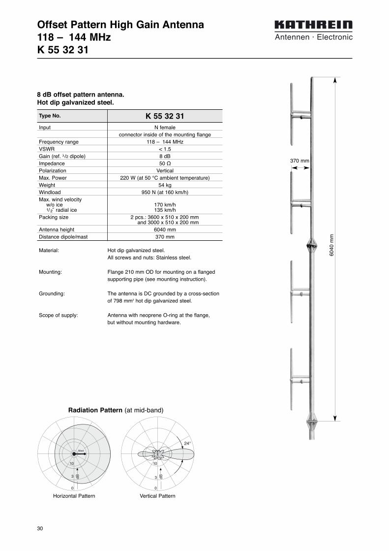
Offset Pattern High Gain Antenna118 – 144 MHzK 55 32 31
Input N femaleconnector inside of the mounting flange
Frequency range 118 – 144 MHzVSWR < 1.5Gain (ref. λ/2 dipole) 8 dBImpedance 50 ΩPolarization VerticalMax. Power 220 W (at 50 °C ambient temperature)Weight 54 kgWindload 950 N (at 160 km/h)Max. wind velocity
w/o ice 170 km/h1/2˝ radial ice 135 km/h
Packing size 2 pcs.: 3600 x 510 x 200 mmand 3000 x 510 x 200 mm
Antenna height 6040 mmDistance dipole/mast 370 mm
Type No. K 55 32 31
8 dB offset pattern antenna.Hot dip galvanized steel.
3 dB
10
0
24°
3 dB
10
0
Mast
Horizontal Pattern Vertical Pattern
6040
mm
370 mm
Radiation Pattern (at mid-band)
Material: Hot dip galvanized steel.All screws and nuts: Stainless steel.
Mounting: Flange 210 mm OD for mounting on a flangedsupporting pipe (see mounting instruction).
Grounding: The antenna is DC grounded by a cross-sectionof 798 mm2 hot dip galvanized steel.
Scope of supply: Antenna with neoprene O-ring at the flange, but without mounting hardware.

31
Mounting InstructionOffset Pattern High Gain AntennaK 55 32 31
ø 18 mm
170 mm210 mm
required metric wrenches:19 mm

32

33
Summary – Filter VHF108 – 144 MHz
Frequency rangeType ... tunable bandwidth Type No. Page
– fixed bandwidth
Band-pass FilterBand-pass Filter 1 cavity 118 ... 144 MHz K 64 21 35 1 34, 35Band-pass Filter 2 cavities 100 ... 156 MHz K 64 12 31 36, 37Band-pass Filter 3 cavities 100 ... 156 MHz K 64 13 31 36, 37
S-P Filter S-P Filter 1 cavitiy 118 ... 144 MHz K 64 21 36 1 38, 39S-P Filter 1 cavitiy 118 ... 144 MHz K 64 21 37 1 38, 39
Band-stop FilterBand-stop Filter 1 cavitiy 118 ... 144 MHz K 64 31 31 40, 41Band-stop Filter 2 cavities 118 ... 144 MHz K 64 32 31 40, 41 Band-stop Filter 3 cavities 118 ... 144 MHz K 64 33 31 40, 41
Filter Transmitter CombinerFilter Transmitter Combiner 2 inputs 118 ... 144 MHz 791 527 42Filter Transmitter Combiner 3 inputs 118 ... 144 MHz 791 526 42Filter Transmitter Combiner 4 inputs 118 ... 144 MHz 791 525 42Filter Transmitter Combiner 5 inputs 118 ... 144 MHz 792 558 42Filter Transmitter Combiner 6 inputs 118 ... 144 MHz 792 504 42Filter Transmitter Combiner 2 inputs 118 ... 144 MHz 784 10198 43
Filter Receiver CombinerFilter Receiver Combiner 2 outputs 118 ... 144 MHz 792 318 44Filter Receiver Combiner 3 outputs 118 ... 144 MHz 791 857 44Filter Receiver Combiner 4 outputs 118 ... 144 MHz 791 859 44Filter Receiver Combiner 5 outputs 118 ... 144 MHz 792 329 44Filter Receiver Combiner 6 outputs 118 ... 144 MHz 792 330 44Filter Receiver Combiner 2 outputs 118 ... 144 MHz 793 094 45Filter Receiver Combiner 3 outputs 118 ... 144 MHz 791 211 45
Coupler3-dB Coupler 100 – 150 MHz K 62 70 31 4610-dB Coupler 100 – 150 MHz 784 10025 47
CirculatorCirculator 118 – 144 MHz 791 653 48
Decoupling unitDecoupling unit 118 – 144 MHz 791 528 49
Receiver MulticouplerReceiver Multicoupler 8 outputs 117.5 – 144 MHz 780 265 50Receiver Multicoupler 16 outputs 117.5 – 144 MHz 780 266 51
Hybrid Transmitter CombinerHybrid Transmitter Combiner 2 intputs 118 – 144 MHz 792 863 52Hybrid Transmitter Combiner 2 intputs 118 – 144 MHz 792 865 52Hybrid Transmitter Combiner 3 intputs 118 – 144 MHz 792 868 52Hybrid Transmitter Combiner 4 intputs 118 – 144 MHz 792 871 52
Examples for customize combinersCombiner System, 6 channels VHF 53Combiner System, 20 channels VHF 54
New Products
Filt
ers
VH
F10
8 –
144
MH
z

34
Type No. K 64 21 35 1
Band-pass Filter118 ... 144 MHz
Frequency range 118 ... 144 MHzInsertion loss 0.5 ... 2 dB, tunableVSWR < 1.5Impedance 50 ΩInput power < 200 WTemperature range –30 … +60 °CConnectors N female, silver-platedMaterial Outer conductor: Aluminium
Inner conductor: Brass, silver-platedInstallation Free standing or
wall mounting with mounting anglesAttached hardware Filter with 2 mounting angles
and 2 connecting piecesWeight 13 kgPacking size 207 mm x 1125 mm x 207 mmDimensions (w x h x d) 190 mm x max. 980 mm x 190 mm (with tuning rod)
Technical Data
The band-pass filter is suitable as receivingor transmitting filter, for one transmitting orreceiving channel.
It can be used:– to improve the input selectivity of receivers
and amplifiers,– to increase the isolation of transmitters,
whose respective antennas are mountedclose together,
– to suppress noise sidebands and inter-modulation products,
– as a component to form combiners.
Design and construction:The band-pass filter is designed as a tempe-rature stabilized λ/4 coaxial resonator. Thepass band frequency as well as the inputand output coupling are adjustable.
Filter characteristics: Narrow pass band range with low insertionloss, high stop band attenuation, variable fil-ter response corresponding to the desiredstop band attenuation.
Combination of several band-pass filters:Several band-pass filters can be intercon-nected using cables of an electrical length ofλ/4. This causes an increase in the edgesteepness of the filter curve as well as thebandwidth of the pass band. The individualfilters are tuned to the center frequency ofthe complete filter.
Insertion loss of the filter combination = Sum insertion loss of the individual filters + cable attenuation of the interconnectingcables (about 0.1 dB per cable). Stop band attenuation of the filter combination = Sum stop band attenuation of individual fil-ters + additional stop band attenuation.
If the stop band attenuation of the individualfilters exceeds 10 dB, approximately the fol-lowing applies: additional stop band attenuation = (n – 1) x 5 dB;n = number of individual filters.For special applications band-pass filters canalso be interconnected with S-P filters.
Tuning:The band-pass filter is tuned to the desiredpass band frequency and insertion loss at thefactory. Please specify desired pass band fre-quency and insertion loss (curve A, B, C, D)when ordering. The pass band filter can also be tuned onsite using the supplied instructions.
770
mm
max
.21
0 m
m
190 mm
190 mm
35
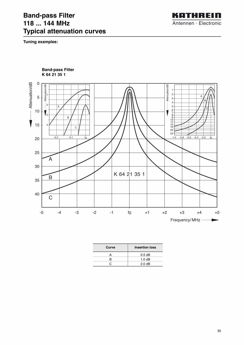
Band-pass Filter118 ... 144 MHzTypical attenuation curves
0
5
10
15
20
25
30
35
40
-5 -4 -3 -2 -1 f0 +1 +2 +3 +4 +5
Atte
nuat
ion/
dB
Frequency/ MHz
A
B
C
K 64 21 35 1
1
2
3
4
-0.2 -0.1 f0
A
B
C
Atte
nuat
ion/
dB
Atte
nuat
ion/
dB
1
2
3
4
56789
101114162024
-1.0 -0.8 -0.6 -0.4 -0.2 f0
A
B
C
Curve Insertion loss
A 0.5 dBB 1.0 dBC 2.0 dB
Tuning examples:
Band-pass FilterK 64 21 35 1
36
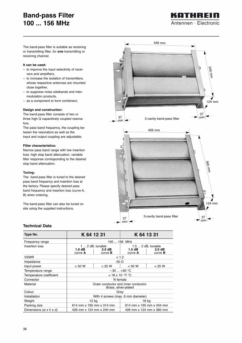
Band-pass Filter100 ... 156 MHz
Technical Data
Type No. K 64 12 31 K 64 13 31Frequency range 100 ... 156 MHzInsertion loss 1 ... 2 dB, tunable 1.5 ... 2 dB, tunable
1.0 dB 2.0 dB 1.5 dB 2.0 dBcurve A curve B curve A curve B
VSWR < 1.2Impedance 50 ΩInput power < 50 W < 25 W < 50 W < 25 WTemperature range – 30 ... +60 °CTemperature coefficient < 18 x 10 –6/ °CConnector N femaleMaterial Outer conductor and inner conductor:
Brass, silver-platedColour GreyInstallation With 4 screws (max. 6 mm diameter)Weight 12 kg 18 kgPacking size 614 mm x 195 mm x 314 mm 614 mm x 195 mm x 434 mmDimensions (w x h x d) 426 mm x 124 mm x 240 mm 426 mm x 124 mm x 360 mm
2-cavity band-pass filter
3-cavity band-pass filter
426 mm
240 mm
37mm
37mm
426 mm
360 mm
37mm
37mm
The band-pass filter is suitable as receivingor transmitting filter, for one transmitting orreceiving channel.
It can be used:– to improve the input selectivity of recei-
vers and amplifiers,– to increase the isolation of transmitters,
whose respective antennas are mountedclose together,
– to suppress noise sidebands and inter-modulation products,
– as a component to form combiners.
Design and construction:The band-pass filter consists of two orthree high Q capacitively coupled resona-tors. The pass band frequency, the coupling be-tween the resonators as well as the input and output coupling are adjustable.
Filter characteristics: Narrow pass band range with low insertionloss, high stop band attenuation, variablefilter response corresponding to the desiredstop band attenuation.
Tuning:The band-pass filter is tuned to the desiredpass band frequency and insertion loss atthe factory. Please specify desired passband frequency and insertion loss (curve A,B) when ordering.
The band-pass filter can also be tuned onsite using the supplied instructions.
124 mm
124 mm

37
Band-pass Filter100 ... 156 MHzTypical attenuation curves
Atte
nuat
ion/
dB
Frequency/MHz
2
4
6
8
10
-0.4 -0.2 f0
A
B
Atte
nuat
ion/
dB
A
B
-8 -6 -4 -2 f0
10
20
30
40
50
60
70
-3 -2 -1 f0
10
20
30
40
50
60
70
A
B
Atte
nuat
ion/
dB
Frequency/MHz
-0.2 -0.1 f0
2
4
6
8
10
A
Atte
nuat
ion/
dB
B
2-cavity band-pass filter K 64 12 31 3-cavity band-pass filter K 64 13 31
Curve Model Insertion Type No.loss
A 2 cavities 1.0 dB K 64 12 31B 2 cavities 2.0 dB K 64 12 31A 3 cavities 1.5 dB K 64 13 31B 3 cavities 2.0 dB K 64 13 31
Tuning examples:

38
Type No. K 64 21 36 1 K64 21 37 1
S-P Filter118 ... 144 MHz
Pass frequency Below stop frequency Above stop frequencyFrequency range 118 ... 144 MHzFrequency separtion
Minimum 0.2 MHzMaximum 5 MHz
Insertion loss 0.5 ±0.15 dBVSWR < 1.5Impedance 50 ΩInput power < 200 WTemperature range –20 … +60 °CEffect of temperature < 0.2 kHz / °CConnectors N femaleMaterial Outer conductor: Aluminium
Inner conductor: Brass, silver-platedInstallation Free standing or
wall mounting with mounting anglesAttached hardware S-P filter with 2 mounting angles
and 2 connecting piecesWeight 13 kgPacking size 207 mm x 1125 mm x 207 mmDimensions (w x h x d) 190 mm x max. 980 mm x 190 mm (with tuning rod)
Technical Data77
0 m
m
max
.21
0 m
m
The S-P filter (Stop-Pass filter) is used toattenuate interfering signals located extreme-ly close to the operational frequency.
It can be used:– in the transmission path to suppress
side band noise and to attenuate inter-modulation products at the receiving fre-quencies,
– in the receiving path to attenuate transmit-ting frequencies,
– as a component for combiners with verylow frequency spacing.
Design and construction:The S-P filter is designed as a high Q tempe-rature stabilized λ/4 coaxial resonator. Usinga special temperature stabilized coupling,high stop band attenuation can be adjustedvery close to the pass band frequency.
Filter characteristics: Narrow pass band range with low insertionloss, high stop band attenuation at the stopband frequency. Even in case of very smallspacing between the pass band and the stopband frequency a high stop band attenuationis achieved, which can not be achievedusing standard band-pass filters of the samesize.
Combination of several S-P filters:Several S-P filters can be interconnected bycables with an electrical length of λ/4.
Insertion loss of the filter combination = Sum insertion loss of the individual filters + cable attenuation of the interconnectingcables (about 0.1 dB per cable). Stop bandattenuation of the filter combination = Sum stop band attenuation of the individualfilters + additional stop band attenuation.
If the stop band attenuation of the individualfilters exceeds 10 dB, approximately the following applies:additional stop band attenuation =(n – 1) x 5 dB;n = number of individual filters.For special applications S-P filters can alsobe interconnected with band-pass filters.
Tuning:The S-P filter is tuned to the desired passband and stop band frequency at the factory.Please specify desired pass band and stopband frequency when ordering.
The S-P filter can also be tuned on site usingthe supplied instructions.
190 mm
190 mm

39
S-P Filter118 ... 144 MHzTypical attenuation curves
CurveFrequency separation
stop band frequency / pass band frequency
A 0.2 MHzB 0.3 MHzC 0.4 MHzD 0.5 MHzE 0.6 MHzF 0.8 MHzG 1.0 MHzH 1.2 MHz
f0 +0.2 +0.4 +0.6 +0.8 +1.0 +1.2
0
5
10
15
20
25
30
35
40
45
-0.3 -0.1 f0
1
2
3
4
dB
ABCDEFGH
A
BC
DE
F
G
H
-0.2 f0 0.1
Frequency/MHz
Atte
nuat
ion/
dB
0
5
10
15
20
25
30
35
40
45-1.2 -1.0 -0.8 -0.6 -0.4 -0.2 f0
f0 +0.2
-0.1 f0 0.2
1
2
3
4
ABCDEFGH
A
B
DE
F
G
H
C
Atte
nuat
ion/
dB
Frequency/MHz
dB
Tuning examples:
K 64 21 36 1Pass frequency below stop frequency
K 64 21 37 1Pass frequency above stop frequency
40
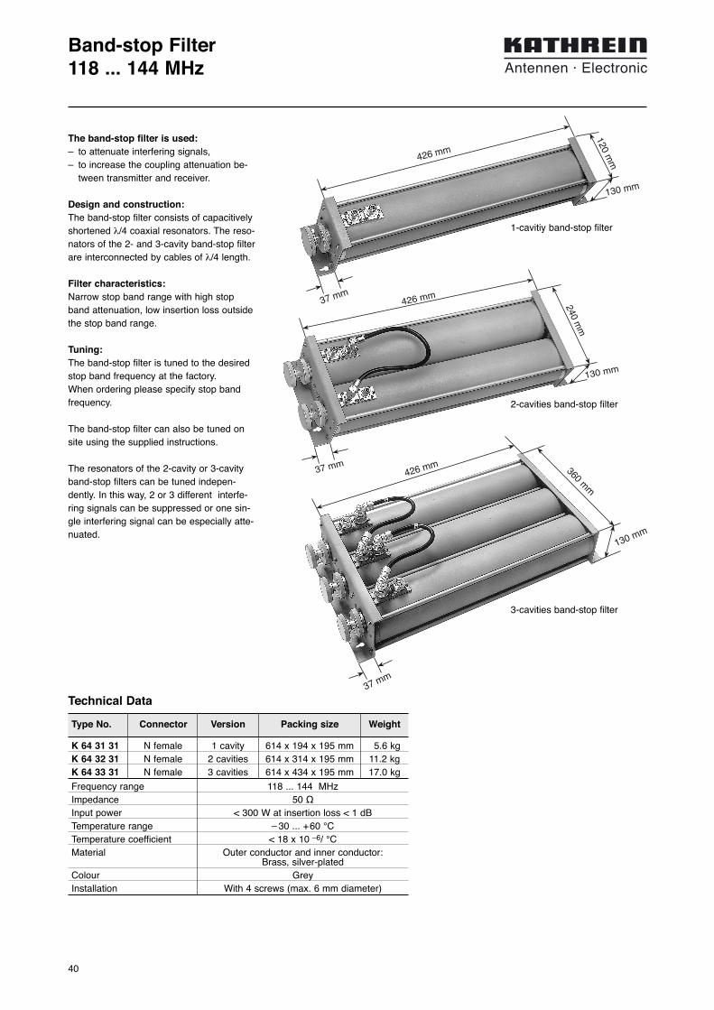
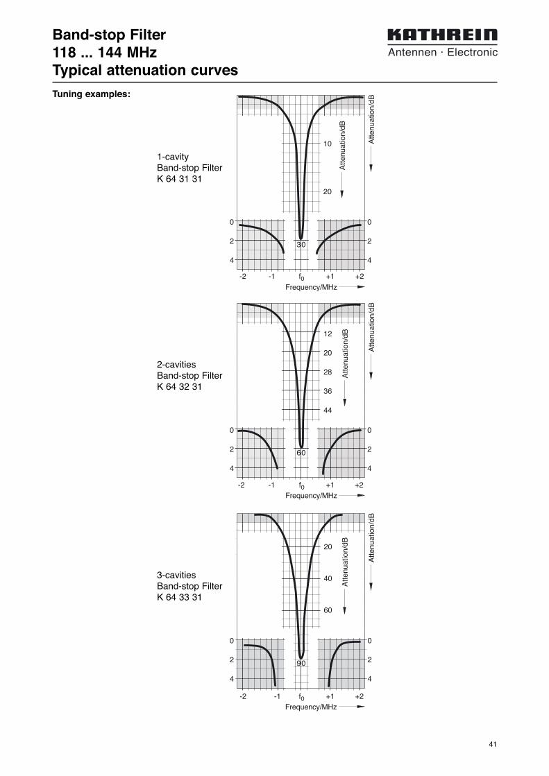
Band-stop Filter118 ... 144 MHz
Technical Data
Type No. Connector Version Packing size Weight
Frequency range 118 ... 144 MHzImpedance 50 ΩInput power < 300 W at insertion loss < 1 dBTemperature range – 30 ... +60 °CTemperature coefficient < 18 x 10 –6/ °CMaterial Outer conductor and inner conductor:
Brass, silver-platedColour GreyInstallation With 4 screws (max. 6 mm diameter)
K 64 31 31 N female 1 cavity 614 x 194 x 195 mm 5.6 kgK 64 32 31 N female 2 cavities 614 x 314 x 195 mm 11.2 kgK 64 33 31 N female 3 cavities 614 x 434 x 195 mm 17.0 kg
426 mm
360 mm
130 mm
426 mm
37 mm
3-cavities band-stop filter
240 mm
130 mm
426 mm
37 mm
2-cavities band-stop filter
The band-stop filter is used:– to attenuate interfering signals,– to increase the coupling attenuation be-
tween transmitter and receiver.
Design and construction:The band-stop filter consists of capacitivelyshortened λ/4 coaxial resonators. The reso-nators of the 2- and 3-cavity band-stop filterare interconnected by cables of λ/4 length.
Filter characteristics: Narrow stop band range with high stopband attenuation, low insertion loss outsidethe stop band range.
Tuning:The band-stop filter is tuned to the desiredstop band frequency at the factory. When ordering please specify stop bandfrequency.
The band-stop filter can also be tuned onsite using the supplied instructions.
The resonators of the 2-cavity or 3-cavityband-stop filters can be tuned indepen-dently. In this way, 2 or 3 different interfe-ring signals can be suppressed or one sin-gle interfering signal can be especially atte-nuated.
120 mm
130 mm
426 mm
37 mm
1-cavitiy band-stop filter
41
Band-stop Filter118 ... 144 MHzTypical attenuation curves
-2 -1 f0 +1 +2
30
0
2
4
0
2
4
10
20
Atte
nuat
ion/
dB
Atte
nuat
ion/
dB
Frequency/MHz
-2 -1 f0 +1 +2
60
0
2
4
0
2
4
12
20
28
36
44
Atte
nuat
ion/
dB
Atte
nuat
ion/
dB
Frequency/MHz
90
0
2
4
0
2
4
-2 -1 f0 +1 +2
20
40
60
Atte
nuat
ion/
dB
Atte
nuat
ion/
dB
Frequency/MHz
1-cavityBand-stop FilterK 64 31 31
2-cavitiesBand-stop FilterK 64 32 31
3-cavitiesBand-stop FilterK 64 33 31
Tuning examples:
42
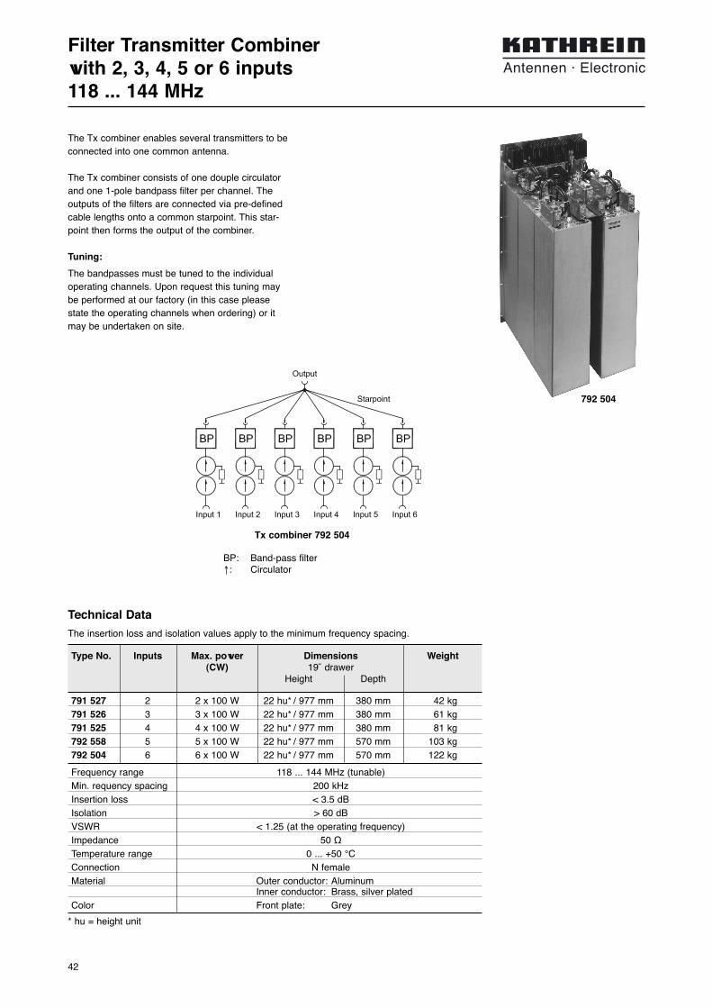
Filter Transmitter Combinerwith 2, 3, 4, 5 or 6 inputs118 ... 144 MHz
Technical Data
The insertion loss and isolation values apply to the minimum frequency spacing.
The Tx combiner enables several transmitters to beconnected into one common antenna.
The Tx combiner consists of one douple circulatorand one 1-pole bandpass filter per channel. Theoutputs of the filters are connected via pre-definedcable lengths onto a common starpoint. This star-point then forms the output of the combiner.
Tuning:
The bandpasses must be tuned to the individualoperating channels. Upon request this tuning maybe performed at our factory (in this case pleasestate the operating channels when ordering) or itmay be undertaken on site.
Type No. Inputs Max. power Dimensions Weight(CW) 19˝ drawer
Height Depth
791 527 2 2 x 100 W 22 hu* / 977 mm 380 mm 42 kg791 526 3 3 x 100 W 22 hu* / 977 mm 380 mm 61 kg791 525 4 4 x 100 W 22 hu* / 977 mm 380 mm 81 kg792 558 5 5 x 100 W 22 hu* / 977 mm 570 mm 103 kg792 504 6 6 x 100 W 22 hu* / 977 mm 570 mm 122 kg
Frequency range 118 ... 144 MHz (tunable)Min. requency spacing 200 kHzInsertion loss < 3.5 dBIsolation > 60 dBVSWR < 1.25 (at the operating frequency)Impedance 50 ΩTemperature range 0 ... +50 °CConnection N femaleMaterial Outer conductor: Aluminum
Inner conductor: Brass, silver platedColor Front plate: Grey
* hu = height unit
Tx combiner 792 504
BP: Band-pass filter↑: Circulator
792 504

43
Filter Transmitter Combinerfor narrow frequency spacing118 ... 144 MHz
Type No. 784 10198Inputs 2Frequency range 118 ... 144 MHz (tunable)Min. frequency spacing 100 kHzInsertion loss < 5.5 dBIsolation > 60 dBVSWR < 1.25Impedance 50 ΩInput power (CW) 2 x 100 WTemperatur range 0 ... +50 °CConnectors N femaleMaterial Outer conductor: Aluminum
Inner conductor: Brass, silver platedColour of front plate GreyWeight 68 kgDimensions 19˝ drawer
(height: 22 hu* = 977 mm, depth: 380 mm)
* hu = height unit
Technical DataThe insertion loss and isolation values apply to the minimum frequency spacing.
The Tx combiner enables two transmitters to becombined to one common antenna output.
The Tx combiner consists of one douple circulatorand two 1 pole band-pass filters per channel.
The outputs of the filters are connected via pre-defined cable lengths onto a common starpoint.This starpoint then forms the output of the combi-ner.
Tuning:
The band-passes must be tuned to the individualoperating channels. Upon request this tuning maybe performed at our factory (in this case please state the operating channels when ordering) or it may be undertaken on site.
BP: Band-pass filter↑: Circulator

44
Filter Receiver Combinerwith 2, 3, 4, 5 or 6 outputs118 ... 144 MHz
Type No. Outputs Dimensions Weight19˝ drawer
Height Depth
792 318 2 22 hu* / 977 mm 190 mm 36 kg791 857 3 22 hu* / 977 mm 380 mm 49 kg791 859 4 22 hu* / 977 mm 380 mm 62 kg792 329 5 22 hu* / 977 mm 570 mm 75 kg792 330 6 22 hu* / 977 mm 570 mm 88 kg
Frequency range 118 ... 144 MHz (tunable)Min. frequency spacing 200 kHzInsertion loss ≤ 2.5 dBIsolation ≥ 18 dBVSWR < 1.5Impedance 50 ΩTemperature range 0 ... +50 °CConnection N femaleMaterial Outer conductor: Aluminum
Inner conductor: Brass, silver platedColor Front plate: Grey
* hu = height unit
Input
Output 2Output 1 Output 3 Output 4
BP BP BP BP
Starpoint
Technical Data
The insertion loss and isolation values apply to the minimum frequency spacing.
The Rx combiner enables several receivers to becombined to one common antenna input.
The Rx combiner consists of one 1-pole band-passfilter per channel.The inputs of the filters are connected via pre-defi-ned cable lengths onto a common starpoint. This starpoint then forms the input of the combiner.
Tuning:
The bandpasses must be tuned to the individualoperating channels. Upon request this tuning maybe performed at our factory (in this case please state the operating channels when ordering) or itmay be undertaken on site.
Rx combiner 791 859BP: Band-pass filter
791 859

45
Filter Receiver Combinerfor narrow frequency spacing118 ... 144 MHz
Type No. 793 094 791 211Outputs 2 3Frequency range 118 ... 144 MHz (tunable)Min. frequency spacing 100 kHzInsertion loss < 4.5 dBIsolation > 18 dBVSWR < 1.25Impedance 50 ΩTemperatur range 0 ... +50 °CConnectors N femaleMaterial Outer conductor: Aluminum
Inner conductor: Brass, silver platedColour of front plate GreyWeight 62 kg 88 kgDimensions 19˝ drawer 19˝ drawer
(22 hu* = 977 mm, depth: 380 mm) (22 hu* = 977 mm, depth: 570 mm)* hu = height unit
Technical DataThe insertion loss and isolation values apply to the minimum frequency spacing.
The Rx combiner enables two receivers to be com-bined to one common antenna output.
The Rx combiner consists of two 1 pole band-passfilters per channel.
The band-pass filter is designed as a temperaturestabilized λ/4 coaxial resonator.
The intputs of the filters are connected via pre-defi-ned cable lengths onto a common starpoint.This starpoint then forms the input of the combiner.
Tuning:
The band-passes must be tuned to the individualoperating channels. Upon request this tuning maybe performed at our factory (in this case please state the operating channels when ordering) or it may be undertaken on site.
793 094
793 094
791 211
BP: Band-pass filter

46
3-dB Coupler (90° Hybrid)100 – 150 MHz
Type No. K 62 70 31Connectors N femaleFrequency range 100 – 150 MHzAttenuation 1 ↔ 2 / 1 ↔ 3 3 ±0.4 dBAttenuation 2 ↔ 3 See diagramDirectivity > 35 dBVSWR < 1.06Impedance 50 ΩMax. power 500 WMaterial Brass, silver-platedColour GreyInstallation With 2 screws (max. 6 mm diameter)Weight 1.6 kgPacking size 931 mm x 54 mm x 126 mmDimensions (w x h x d) 625 mm x 40 mm x 95 mm
(incl. connectors)
Note: VSWR and attenuation are measured when the remaining ports are terminated with 50-Ω loads.
Technical Data
2.5
3.0
3.5
Frequency/MHz
1↔ 2
1↔ 3
150
Typical attenuation 1↔ 2 and 1↔ 3vs frequency
Atte
nuat
ion
1↔
3 /
dB
Atte
nuat
ion
1↔
2 /
dB
1 3
2 4
100
1.0 1.5 2.0
15
20
25
Atte
nuat
ion
2 ↔
3 /
dB
VSWR at port 1(with 50 Ω load at port 4)
Attenuation 2 ↔ 3 vs VSWR at port 1
The 3-dB coupler can be used:– as decoupled power splitter with a ratio
of 1:1,– for the decoupled combining of two trans-
mitters with arbitrarily low frequency spa-cing (at 3-dB loss),
– for the decoupled combining of two recei-vers with arbitrarily low frequency spacing,
– for the decoupled combining of two trans-mitter/receiver units, whose integratedduplexers are within the same frequencyrange, as a frequency independent 90°phase shifter,
– as a component to form combiners.
Design and function:The 3-dB coupler has four ports, two ofwhich are decoupled from each other. For example effective power entering intoport 1 is distributed into ports 2 and 3. Port 4 is decoupled and without power ifports 2 and 3 are ideally matched. In practi-ce an absorber of suitable power is to be planned for according to the mismatchof ports 2 and 3.
Custom versions:On request couplers with a coupling atte-nuation between 3 dB and 10 dB are available.

47
Type No. 784 10025Connectors N femaleFrequency range 100 – 150 MHzAttenuation 1 ↔ 3 (4 ↔ 2) 0.5 ±0.2 dBAttenuation 1 ↔ 2 (4 ↔ 3) 10 ±0.5 dBDirectivity > 30 dBVSWR < 1.1Impedance 50 ΩMax. power 500 WMaterial Brass, silver-platedColour GreyInstallation With 2 screws (max. 6 mm diameter)Weight 1.6 kgPacking size 931 mm x 54 mm x 126 mmDimensions (w x h x d) 625 mm x 40 mm x 95 mm (incl. connectors)
Note: VSWR and attenuation are measured when the remaining ports are terminated with 50-Ω loads.
Technical Data
1 3
2 4
The 10-dB coupler is used as a decoupled split-ter for power splitting purposes at a 1 : 9 ratio. An effective power entering at e.g. port 1 is divi-ded between the ports 2 and 3 at a ratio of 1 : 9. Thus 1/10 of the input power (attenuation: 10 dB)is available at port 2 and 9/10 of the input poweris available at port 3.Port 4 is decoupled and remains free of power ifthe ports 2 and 3 are ideally matched. In practicean absorber of suitable power at port 4 is to beplanned in accordance with the mismatch of ports2 and 3.
Decoupled combining can be achieved via thediagonally opposite ports 2 and 3 respectively 1and 4.
10-dB Coupler (90° Hybrid)100 – 150 MHz
48
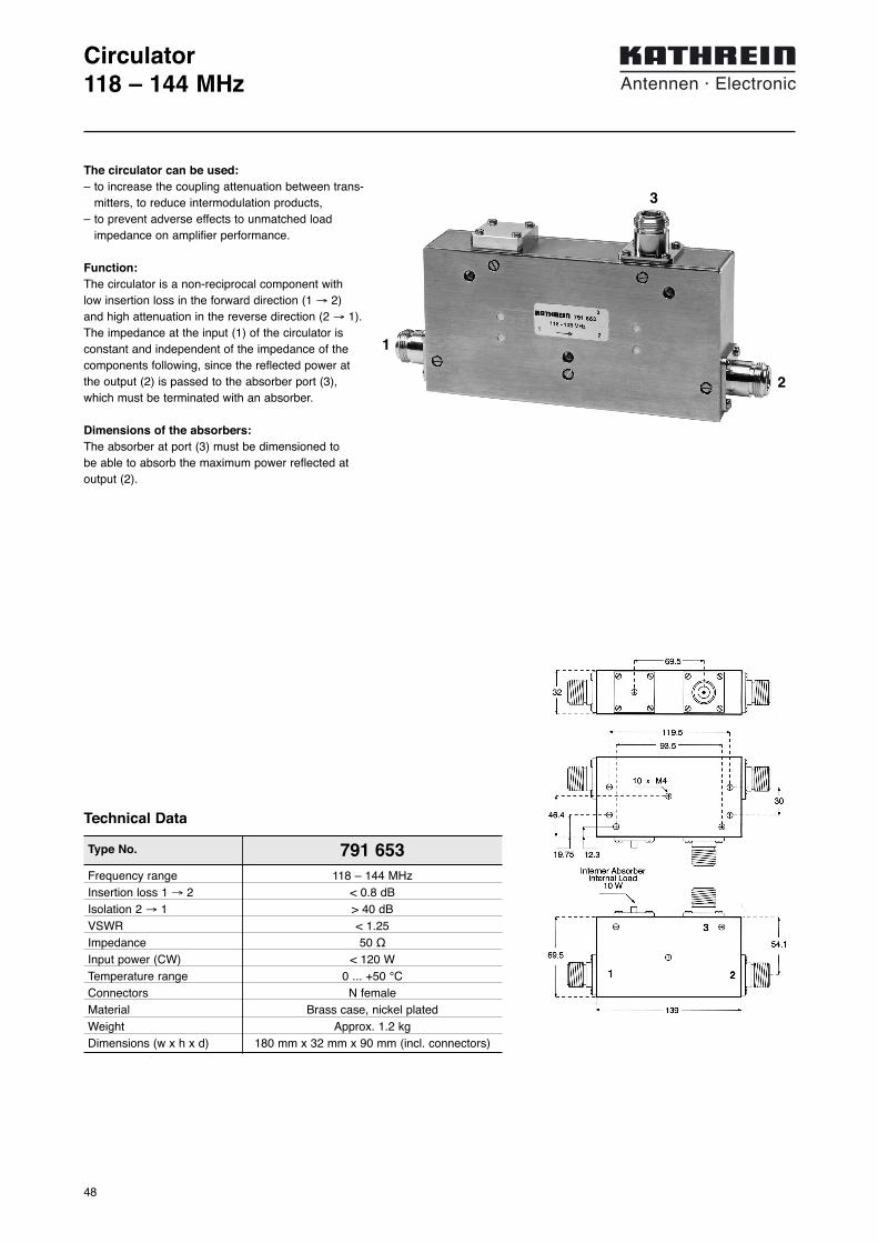
Type No. 791 653
Circulator118 – 144 MHz
Frequency range 118 – 144 MHzInsertion loss 1 → 2 < 0.8 dBIsolation 2 → 1 > 40 dBVSWR < 1.25Impedance 50 ΩInput power (CW) < 120 WTemperature range 0 ... +50 °CConnectors N femaleMaterial Brass case, nickel platedWeight Approx. 1.2 kgDimensions (w x h x d) 180 mm x 32 mm x 90 mm (incl. connectors)
Technical Data
The circulator can be used:– to increase the coupling attenuation between trans-
mitters, to reduce intermodulation products,– to prevent adverse effects to unmatched load
impedance on amplifier performance.
Function:The circulator is a non-reciprocal component with low insertion loss in the forward direction (1 → 2) and high attenuation in the reverse direction (2 → 1).The impedance at the input (1) of the circulator isconstant and independent of the impedance of thecomponents following, since the reflected power atthe output (2) is passed to the absorber port (3),which must be terminated with an absorber.
Dimensions of the absorbers:The absorber at port (3) must be dimensioned to be able to absorb the maximum power reflected atoutput (2).
1
2
3

49
Type No. 791 528
Decoupling unit118 – 144 MHz
Frequency range 118 – 144 MHzInsertion loss 1 ↔ 2 < 0.8 dBIsolation > 40 dBVSWR < 1.25Impedance 50 ΩInput power < 100 WReturn power < 25 WTemperatur range 0 ... +50 °CConnectors N femaleInstallation With 2 screws (max. 4 mm diameter)Weight 1.8 kgPacking size 241 mm x 202 mm x 115 mm
Technical Data
This decoupling unit can be used to increase theisolation between transmitters, if the used antennasare situated very close together.
The decoupling unit consists of a double circulatorand an absorber.
The impedance at the input of the decoupling unit is constant and is independent of the antenna’sVSWR. The signal received or reflected by theantenna is fed to the absorber.
1Input
Output2
25 W
50
178
210

50
Number of inputs 1Number of outputs 8Frequency range 117.5 – 144 MHzGain 3.0 dB ±1.5 dBNoise figure 4.0 dB +0.5 dB3rd order intercept point > 23 dBm (typ. 25 dBm)Isolation > 25 dB (typ. 30 dB) between any two outputsVSWR
Input < 1.4Output < 1.4
Impedance 50 ΩPower supply 230 V +10/–15%, 50 … 60 Hz and/or
+11 … +48 V DCPower consumption < 9 W (230 V, 50 Hz)
< 20 W (+11 … +48 V DC)Temperature range –20 … +50 °CConnectors N femaleColour Front panel: GreyAttached hardware Power cable and 4 pin DC-connectorWeight 3.9 kgPacking size Approx. 540 mm x 105 mm x 410 mmDimensions (w x h x d) 483 mm x 44 mm x 250 mm, 19˝ drawer
Note: Unused outputs have to be terminated using a 50-Ω load in order to comply with the specifications.
Type No. 780 265
Receiver Multicoupler117.5 – 144 MHz, 8 Outputs
Technical Data
The use of the receiver multicoupler 780 265 isappropriate if several receivers are operatedsimultaneously at the same site. With this receivermulticoupler up to 8 receivers can be connected to one common antenna.This results in considerable savings for the antennasystem. The low noise figure and the excellent inter-modulation properties guarantee a high dynamic rangeand thereby improved receiving conditions. This is ofparticular significance in locations where transmitters are also operated next to receivers.
The receiver multicoupler consists of:– a low noise amplifier,– a power splitter,– a voltage supply.
The receiver multicoupler has an active redundancy dueto the two amplifier modules in parallel which are locatedin the low noise amplifier. This means that the receivermulticoupler still supplies all connected receivers even ifone of the amplifier modules fails. The signal levels in thiscase decrease by approximately 6 dB.Each amplifier module is designed for operation with itsown voltage supply of 230 V AC or +11 … +48 V DC.
Receiver multicoupler
Receiver Receiver Receiver Receiver Receiver
117.5 MHz 144
Example receiver multicoupler117.5 – 144 MHz
8 receivers
active redundantamplifier
decoupleddistributing
network
out-puts
Block diagram receiver multicoupler
Front view
Back view

51
Receiver Multicoupler117.5 – 144 MHz, 16 Outputs
Receiver multicoupler
Receiver Receiver Receiver Receiver Receiver
117.5 MHz 144
Example receiver multicoupler117.5 – 144 MHz
16 receivers
active redundantamplifier
decoupleddistributing
network
out-puts
Block diagram receiver multicoupler
Number of inputs 1Number of outputs 16Frequency range 117.5 – 144 MHzGain 1.0 dB ±1.5 dBNoise figure 4.5 dB ±0.5 dB3rd order intercept point > 12 dBm (typ. 16 dBm)Isolation > 25 dB (typ. 30 dB) between any two outputsVSWR
Input < 1.4Output < 1.4
Impedance 50 ΩPower supply 230 V +10/–15%, 50 … 60 Hz and/or
+11 … +48 V DC, minus groundedPower consumption < 9 W (230 V, 50 Hz)
< 20 W (+11 … +48 V DC)Temperature range –20 … +50 °CConnectors N femaleColour Front panel: GreyAttached hardware Power cable and 4 pin DC-connectorWeight 5.9 kgPacking size Approx. 540 mm x 115 mm x 460 mmDimensions (w x h x d) 483 mm x 88 mm x 250 mm, 19˝ drawer
Note: Unused outputs have to be terminated using a 50-Ω load in order to comply with the specifications.
Type No. 780 266
Technical Data
The use of the receiver multicoupler 780 266 isappropriate if several receivers are operatedsimultaneously at the same site. With this receivermulticoupler up to 16 receivers can be connected to one common antenna.This results in considerable savings for the antenna sys-tem. The low noise figure and the excellent inter-modulation properties guarantee a high dynamic rangeand thereby improved receiving conditions. This is ofparticular significance in locations where transmitters are also operated next to receivers.
The receiver multicoupler consists of:– a low noise amplifier,– a power splitter,– a voltage supply.
The receiver multicoupler has an active redundancy dueto the two amplifier modules in parallel which are locatedin the low noise amplifier. This means that the receivermulticoupler still supplies all connected receivers even ifone of the amplifier modules fails. The signal levels in thiscase decrease by approximately 6 dB.Each amplifier module is designed for operation with itsown voltage supply of 230 V AC or +11 … +48 V DC.
780 266 Front view
780 266 Rearside
52
Type No. Inputs Insertion loss Dimensions Input power19˝ drawer per input
height plug-in depth
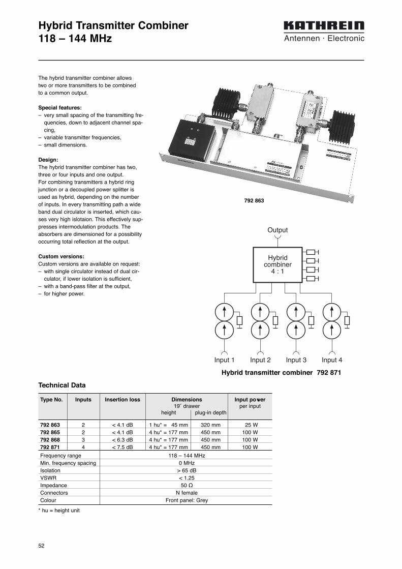
Hybrid Transmitter Combiner118 – 144 MHz
792 863 2 < 4.1 dB 1 hu* = 45 mm 320 mm 25 W792 865 2 < 4.1 dB 4 hu* = 177 mm 450 mm 100 W792 868 3 < 6.3 dB 4 hu* = 177 mm 450 mm 100 W792 871 4 < 7.5 dB 4 hu* = 177 mm 450 mm 100 W
Frequency range 118 – 144 MHzMin. frequency spacing 0 MHzIsolation > 65 dBVSWR < 1.25Impedance 50 ΩConnectors N femaleColour Front panel: Grey
* hu = height unit
Technical Data
The hybrid transmitter combiner allows two or more transmitters to be combined to a common output.
Special features:– very small spacing of the transmitting fre-
quencies, down to adjacent channel spa-cing,
– variable transmitter frequencies,– small dimensions.
Design:The hybrid transmitter combiner has two,three or four inputs and one output. For combining transmitters a hybrid ringjunction or a decoupled power splitter isused as hybrid, depending on the numberof inputs. In every transmitting path a wideband dual circulator is inserted, which cau-ses very high islotaion. This effectively sup-presses intermodulation products. Theabsorbers are dimensioned for a possibilityoccurring total reflection at the output.
Custom versions:Custom versions are available on request:– with single circulator instead of dual cir-
culator, if lower isolation is sufficient,– with a band-pass filter at the output,– for higher power.
792 863
Output
Hybridcombiner
4 : 1
Input 2Input 1 Input 3 Input 4
Hybrid transmitter combiner 792 871

53
Combiner System6 channels VHFExample
Frequency range: 118 ... 144 MHz
Input power: < 100 W
Insertion loss: Tx A: < 3.5 dBB Rx: < 2.5 dB
Isolation: Tx Tx: > 60 dBTx Rx: > 65 dBRx Rx: > 18 dB
6 channelRx filter combiner
792 330
Rx 2 Rx 3Rx 1 Rx 5 Rx 6Rx 4
B
Rx antenna
appr. 50 dB antennascoupling attentuation at
6 meters vertical spacing
6 channelTx filter combiner
792 504
Tx 2 Tx 3Tx 1 Tx 5 Tx 6Tx 4
A
Tx antenna

54
Tx/Rx Combiner20 channels VHFExample
Rx
mul
ticou
pler
780
266
Fre
quen
cy r
ange
: 118
... 1
37 M
Hz
Not
e: R
x si
te is
loca
ted
1000
met
ers
from
Tx
site
.
4 ch
anne
lfil
ter
tran
smitt
er c
ombi
ner
791
525
Tx
2T
x 1
Tx
3T
x 4
Tx
6T
x 5
Tx
7T
x 8
Tx
10T
x 9
Tx
11T
x12
Tx
14T
x13
Tx
15T
x16
Tx
18T
x17
Tx
19T
x20
A 1
A 2
A 3
A 4
A 5
Rx
mul
ticou
pler
780
265
Rx
1 –
Rx
16R
x 17
– R
x 20
Tx
ante
nna
Tx
ante
nna
Rx
ante
nna
appr
. 25
dBan
tenn
as c
oupl
ing
atte
ntua
tion
at 6
met
ers
horiz
onta
l spa
cing
appr
. 65
dBan
tenn
as c
oupl
ing
atte
ntua
tion
at 1
000
met
ers
spac
ing
B 1
B 2
4 x
2 W
K 6
2 26
11
1
Mul
tiple
-uni
tan
tenn
a71
7 58
7
Mul
tiple
-uni
tan
tenn
a71
7 58
7
Mul
tiple
-uni
tan
tenn
a71
7 28
0
Inpu
t pow
er:
< 1
00 W
Inse
rtio
n lo
ss:
Tx
A:
< 3
.5 d
BB
Rx:
> 1
.5 d
B g
ain
Isol
atio
n:T
xT
x:>
60
dBT
xR
x:>
65
dBR
x R
x:>
25
dB
4 ch
anne
lfil
ter
tran
smitt
er c
ombi
ner
791
525
4 ch
anne
lfil
ter
tran
smitt
er c
ombi
ner
791
525
4 ch
anne
lfil
ter
tran
smitt
er c
ombi
ner
791
525
4 ch
anne
lfil
ter
tran
smitt
er c
ombi
ner
791
525

55
OmniOmni 118 – 144 / 225 – 400 MHz 360° 0 dB / 1 dB 2x N-female 717 338 3600 56, 57Omni 118 – 144 / 225 – 400 MHz 360° 0 dB / 1 dB 2x N-female 727 728 3600 56, 57
Multiple-Unit OmniMultiple-Unit Omni 118 – 137 / 225 – 400 MHz 360° 0 dB / 1 dB 4x N-female 723 904 7000 58, 59
Summary – Combination VHF/UHF108 – 144 MHz / 225 – 380 MHz
Type Frequency Gain Connector Type No. Height Pagerange [mm]
An
ten
nas
VH
F/U
HF
Co
mb
inat
ion
New Products
56
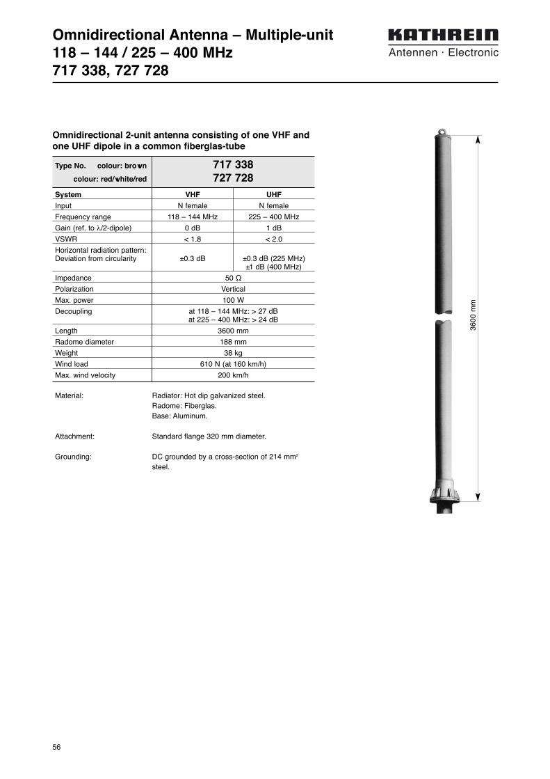
Omnidirectional Antenna – Multiple-unit118 – 144 / 225 – 400 MHz717 338, 727 728
Omnidirectional 2-unit antenna consisting of one VHF andone UHF dipole in a common fiberglas-tube
3600
mm
System VHF UHF
Input N female N female
Frequency range 118 – 144 MHz 225 – 400 MHz
Gain (ref. to λ/2-dipole) 0 dB 1 dB
VSWR < 1.8 < 2.0
Horizontal radiation pattern:Deviation from circularity ±0.3 dB ±0.3 dB (225 MHz)
±1 dB (400 MHz)
Impedance 50 Ω
Polarization Vertical
Max. power 100 W
Decoupling at 118 – 144 MHz: > 27 dBat 225 – 400 MHz: > 24 dB
Length 3600 mm
Radome diameter 188 mm
Weight 38 kg
Wind load 610 N (at 160 km/h)
Max. wind velocity 200 km/h
Type No. colour: brown 717 338colour: red/white/red 727 728
Material: Radiator: Hot dip galvanized steel.Radome: Fiberglas.Base: Aluminum.
Attachment: Standard flange 320 mm diameter.
Grounding: DC grounded by a cross-section of 214 mm2
steel.

57
Mounting InstructionOmnidirectional Antenna717 338, 727 728
– Mount the aluminum flange on plane surface only (max. unevenness 0.5 mm)
– Put the O-ring carefully into the circular groove of the flange
– Mounting screws: M16 stainless or hot dip galvanized steelMounting screws: M 16 (min. strength 5.6 accord. DIN 267)Max. torque: 50 Nm (screws should be greased with MoS2)
– Put a stainless steel washer between aluminum flange and screw head or nut
280 mm
320 mm
18 mm

58
Multiple-Unit Antenna118 – 137 MHz / 225 – 400 MHz723 904
Type No. 723 904System VHF UHFInput 2 x N female 2 x N femaleConnector position Bottom BottomFrequency range 118 – 137 MHz 225 – 400 MHzVSWR < 1.8 < 2.0Horizontal radiation pattern:Deviation from circularity < ±0.3 dB < ±1 dBGain 0 dB 1 dB
(ref. to the half wave dipole)Impedance 50 Ω 50 ΩPolarization Vertical VerticalMax. power 100 W 100 W
(at 50 °C ambient temperature)Decoupling UHF – UHF: > 25 dB
VHF – VHF: > 25 dBUHF – VHF: > 20 dB
Weight 80 kgWind load 900 N (at 160 km/h)Max. wind velocity 200 km/hBending moment (y–y) 2570 Nm (at 160 km/h)
3760 Nm (at 200 km/h)Height Approx. 7000 mm
Material: Hot dip galvanized steel in fiberglass radome.Colour: Red/white/red. All screws and nuts: Stainless steel.
Mounting: Flange 320 mm diameter.
Grounding: The metal parts of the antenna are DC grounded.
Multiple-antenna consisting of 2 VHF and 2 UHF omni-directional antennas

59
Mounting InstructionMulti-Unit Antenna723 904
– Mount the aluminum flange on plane surface only (max. unevenness 0.5 mm)
– Put the O-ring carefully into the circular groove of the flange
– Mounting screws: M16 stainless or hot dip galvanized steelMounting screws: (min. strength 5.6 accord. DIN 267)Max. torque: 50 Nm (screws should be greased with MoS2)
– Put a stainless steel washer between aluminum flange and screw head or nut
280 mm
320 mm
18 mm

60

61
Omni-directional AntennasOmni 225 – 400 MHz 360° 0 dB 7-16 female 718 217 570 62, 63Omni 225 – 400 MHz 360° 0.5 dB N-female K 75 10 11 Approx.1200 64, 65Omni 225 – 400 MHz 360° 2x 1 dB 2x N-female K 75 40 12 1 2650 66, 67Omni 225 – 400 MHz 360° 3x 1 dB 3x N-female K 75 40 13 1 3690 66, 67Omni 225 – 400 MHz 360° 4x 1 dB 4x N-female K 75 40 14 1 4230 66, 67Omni 225 – 400 MHz 360° 5x 1 dB 5x N-female K 75 40 15 1 5570 66, 67Omni 225 – 400 MHz 360° 3 dB N-female 723 141 2650 66, 67
Directional AntennasDirectional Antennas 225 – 400 MHz 180° 5.5 dB N-female K 75 31 11 1380 68, 69Directional Antennas 225 – 400 MHz 180° 8 dB N-female K 75 32 11 2740 70, 71
Summary – Antennas UHF225 – 380 MHz
Type Frequency Gain Connector Type No. Height Pagerange [mm]
An
ten
nas
UH
F22
5 –
380
MH
z
New Products

62
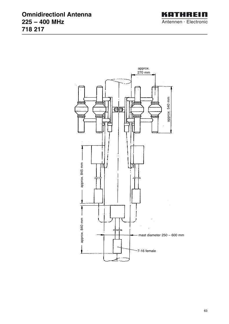
Omnidirectionl Antenna225 – 400 MHz718 217
Input 7-16 femaleFrequency range 225 – 400 MHzVSWR < 2.0Horizontal radiation pattern:
Deviation from circularity Mastdiameter 500 mm:±1.0 dB (225 MHz)±1.5 dB (325 MHz)±3.5 dB (400 MHz)
Gain (ref. λ/2 dipole) 0 dBImpedance 50 ΩPolarization VerticalMax. Power 650 W (at 50 °C ambient temperature)Weight 40 kg (for a mast of 500 mm dia.)Wind load 3.5 kN (at 180 km/h and 4 cm radial ice)Max. wind velocity 200 km/h
Type No. 718 217
Material: Hot-dip galvanized steel.All screws and nuts: Stainless steel.
Mounting: On a pipe mast with a dia. of 400 – 600 mm.Please spezify exact dia. with order.The cable lenth needs to stay unchanged!
Grounding: All parts of the antenna including the deliveredmounting kit are DC grounded.
Scope of supply: Antenna incl. power splitter and cables(pipe mast not supplied).
3 dB
10
0
Vertical Pattern
Radiation Pattern (at mid-band)225 MHz 310 MHz 400 MHz
● 6 dipoles round a mast (diameter 400 – 600 mm), are com-bined by an integrated power splitter.
63
mast diameter 250 – 600 mm
7-16 female
Omnidirectionl Antenna225 – 400 MHz718 217
approx. 270 mm
appr
ox.
540
mm
appr
ox.
845
mm
appr
ox.
840
mm

64
Cone Antenna225 – 400 MHzK 75 10 11
Input N femaleconnector in a weather protective housing
at the end of the support pipeFrequency range 225 – 400 MHzVSWR < 1.8Gain (ref. λ/2 dipole) 0.5 dBImpedance 50 ΩPolarization VerticalMax. Power 290 W (at 50 °C ambient temperature)Weight 9.5 kgWindload 160 N (at 160 km/h)Max. wind velocity 200 km/h (incl. 1/ 2˝ radial ice)Packing size 1250 x 520 x 520 mm
Type No. K 75 10 11
Material: Hot-dip galvanized steel.All screws and nuts: Stainless steel.
Mounting: Parallel mounting at the top of the mast by meansof two butt straps (see mounting instruction).
Grounding: The antenna is DC grounded by a cross-sectionof 400 mm2 hot dip galvanized steel.
Scope of supply: Antenna without mounting hardware.
3 dB
10
0
Vertical Pattern
appr
ox.
500
mm
appr
ox.
700
mm
470 mm
Radiation Pattern (at mid-band)225 MHz 310 MHz 400 MHz

65
Mounting InstructionCone AntennaK 75 10 11
60
25
ø14
50
300

66
Omnidirectional Antenna 225 – 400 MHzK 75 40 1. . , 723 141
Gain (ref. to the 2 x 1 dB 3 x 1 dB 4 x 1 dB 5 x 1 dBλ/2 dipole)
Type No. K 75 40 12 1 K 75 40 13 1 K 75 40 14 1 K 75 40 15 1
Length 2650 mm 3690 mm 4730 mm 5770 mmWeight 29 kg 37 kg 49 kg 67 kgWind load 430 N 590 N 760 N 940 N
at 160 km/hBending moment 560 Nm 1070 Nm 1780 Nm 2690 Nm
at 160 km/h (at attachment point)Radome diameter 188 mmMax. wind velocity 200 km/hFrequency range 225 – 400 MHzBandwidth 175 MHzInput Type N female connectors in the antenna baseVSWR < 2.0Attenuation > 27 dB between adjacent dipolesMax. input power (CW) 110 W (at 50 °C ambient temperature)Polarization Vertical
Gain (ref.to the 3 dBλ/2 dipole)
Type No. 723 141
Material: Radiating elements: Hot dip galvanized steel.Base: Weatherproof aluminum.Radome: Fiberglass, colour: Brown.Intermal screws and nuts: Stainless steel.
Mounting: Flange 320 mm OD for mounting on a flangedsupporting pipe.
Scope of supply: Antenna with neoprene O-ring at the flange, but without screws.
Grounding: The antenna is DC grounded by a cross sectionof 214 mm2 hot dip galvanized steel.
● Multi-element antenna, consisting of several separately fed dipoles arranged in line.
● Special models of gain antennas with an integrated power splitter.
3
0
dB 3
0
dB
78° (45°)
Horizontal Pattern Vertical Pattern
Radiation Pattern 225 MHz .......... 400 MHz
Standard models: Multiple-unit antenna
Special models I: Omni-directional gain antenna
For standard models
Hei
ght

67
Omnidirectional Antenna 225 – 400 MHzK 75 40 1. . , 723 141
– Mount the aluminum flange on plane surface only (max. unevenness 0.5 mm)
– Put the O-ring carefully into the circular groove of the flange
– Mounting screws: M16 stainless or hot dip galvanized steelMounting screws: (min. strength 5.6 according DIN 267)Max. torque: 50 Nm (screws should be greased with MoS2)
– Put a stainless steel washer between aluminum flange and screw head or nut
280 mm
320 mm
18 mm
K 75 40 12 1

68
Offset Pattern Gain Antenna225 – 400 MHzK 75 31 11
Input N femaleconnector inside of the mounting flange
Frequency range 225 – 400 MHzVSWR < 1.7 Gain (ref. λ/2 dipole) 5.5 dB Impedance 50 ΩPolarization VerticalMax. Power 260 W (at 50 °C ambient temperature)Radiation pattern Preferred direction: Mast to radiator.Weight 18 kgWindload 200 N (at 160 km/h)Max. wind velocity 200 km/h (incl. 1/ 2˝ radial ice)Packing size 1450 x 400 x 200 mmAntenna height Approx. 1380 mmDistance dipole/mast 250 mm
Type No. K 75 31 11
5.5 dB offset pattern antennaHot dip galvanized steel
Material: Hot dip galvanized steel.All screws and nuts: Stainless steel.
Mounting: Via standard flange 130 mm diameter. The upper flange is suitable for installation of an obstruction light.
Grounding: All metal parts of the antenna including the mounting kit are DC grounded.
3 dB
10
0
39°/ 29°
3 dB
10
0
180°
Mast
Horizontal Pattern Vertical Pattern
appr
ox.
1380
mm
250 mm
Radiation Pattern (at mid-band)225 MHz 400 MHz

69
Mounting InstructionOffset Pattern Gain AntennaK 75 31 11
100 mm130 mm
ø 14 mm
100 mm130 mm
ø 39 mm
ø 14 mm

70
Offset Pattern High Gain Antenna225 – 400 MHzK 75 32 11
Input N femaleconnector inside of the mounting flange
Frequency range 225 – 400 MHzVSWR < 1.7 Gain (ref. λ/2 dipole) 8 dB Impedance 50 ΩPolarization VerticalMax. Power 300 W (at 50 °C ambient temperature)Weight 40 kgWindload 450 N (at 160 km/h)Max. wind velocity 200 km/h (incl. 1/ 2˝ radial ice)Packing size 2800 x 400 x 200 mmAntenna height 2740 mmDistance dipole/mast 250 mm
Type No. K 75 32 11
8 dB offset pattern antenna.Hot dip galvanized steel.
Material: Hot dip galvanized steel.All screws and nuts: Stainless steel.
Mounting: Via standard flange 190 mm diameter. The upper flange is suitable for installation of an obstruction light.
Grounding: All metal parts of the antenna including the mounting kit are DC grounded.
3 dB
10
0
24°/ 16°
3 dB
10
0
180°
Mast
Horizontal Pattern Vertical Pattern
2740
mm
250 mm
Radiation Pattern (at mid-band)225 MHz 400 MHz

71
Mounting InstructionOffset Pattern High Gain AntennaK 75 32 11
ø 14 mm
100 mm130 mm
ø 39 mm
ø 17 mm
150 mm190 mm
required metric wrenches:19 mm

72
73
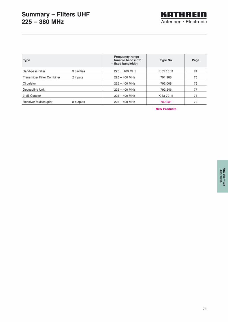
Band-pass Filter 3 cavities 225 ... 400 MHz K 65 13 11 74
Transmitter Filter Combiner 2 inputs 225 – 400 MHz 791 988 75
Circulator 225 – 400 MHz 792 008 76
Decoupling Unit 225 – 400 MHz 792 246 77
3-dB Coupler 225 – 400 MHz K 63 70 11 78
Receiver Multicoupler 8 outputs 225 – 400 MHz 780 231 79
Summary – Filters UHF225 – 380 MHz
Filt
ers
UH
F22
5 –
380
MH
z
Frequency rangeType ... tunable bandwidth Type No. Page
– fixed bandwidth
New Products

74
237
mm
300 mm
105 mm
Band-pass Filter225 ... 400 MHz
The band-pass filter is suitable as receivingor transmitting filter, for one transmitting orreceiving channel.
It can be used:– to improve the input selectivity of recei-
vers and amplifiers,– to increase the isolation of transmitters,
whose respective antennas are mountedclose together,
– to suppress noise sidebands and inter-modulation products,
– as a component to form combiners.
Design and construction:The band-pass filter consists of three high Q capacitively coupled resonators. The pass band frequency, the coupling be-tween the resonators as well as the input and output coupling are adjustable.
Filter characteristics: Narrow pass band range with low insertionloss, high stop band attenuation, variablefilter response corresponding to the desiredstop band attenuation.
Tuning:The band-pass filter is tuned to the desiredpass band frequency and insertion loss atthe factory. Please specify desired passband frequency and insertion loss (curve A,B) when ordering.
The band-pass filter can also be tuned onsite using the supplied instructions.
Technical Data
Type No. K 65 13 11Frequency range 225 ... 400 MHzInsertion loss 1 ... 2 dB, tunable
1.0 dB 2.0 dBcurve A curve B
VSWR < 1.2Impedance 50 ΩInput power < 50 W < 25 WTemperature range – 30 ... +60 °CTemperature coefficient < 15 x 10 –6/ °CConnector N femaleMaterial Outer conductor: Aluminium
Inner conductor: Brass, silver-platedWeight 6.5 kgMounting Via 4 screws (max. 6 mm diameter)Packing size 372 mm x 205 mm x 292 mmDimensions (w x h x d) 300 mm x 105 mm x 237 mm
Atte
nuat
ion/
dB
-6 -4 -2 f0
10
20
30
40
50
60
70
A
B
2
4
6
8
10
-0.8 -0.4 f0
A
B
Atte
nuat
ion/
dB
3-cavities Band-pass Filter K 65 13 11
Tuning example:
Typical attenuation curves
75
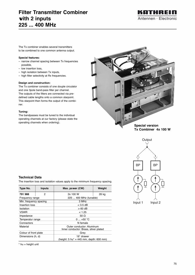
Type No. Inputs Max. power (CW) Weight
Filter Transmitter Combinerwith 2 inputs225 ... 400 MHz
791 988 2 2x 100 W 26 kgFrequency range 225 ... 400 MHz (tunable)Min. frequency spacing 3 MHzInsertion loss < 3.5 dBIsolation > 60 dBVSWR < 1.25Impedance 50 ΩTemperatur range 0 ... +50 °CConnectors N femaleMaterial Outer conductor: Aluminum
Inner conductor: Brass, silver platedColour of front plate GreyDimensions (h, d) 19˝ drawer
(height: 5 hu* = 445 mm, depth: 600 mm)
* hu = height unit
Technical DataThe insertion loss and isolation values apply to the minimum frequency spacing.
The Tx combiner enables several transmitters to be combined to one common antenna output.
Special features:– narrow channel spacing between Tx frequencies
possible,– low insertion loss,– high isolation between Tx inputs,– high filter selectivity at Rx frequencies.
Design and construction:The Tx combiner consists of one douple circulatorand one 3pole band-pass filter per channel. The outputs of the filters are connected via pre-defined cable lengths onto a common starpoint.This starpoint then forms the output of the combi-ner.
Tuning:The bandpasses must be tuned to the individualoperating channels at our factory (please state theoperating channels when ordering).
Output
Input 2Input 1
BP BP
Special versionTx Combiner 4x 100 W

76
Type No. 792 008
Circulator225 – 400 MHz
Frequency range 225 – 400 MHzInsertion loss 1 → 2 < 1.5 dBIsolation 2 → 1 > 38 dBVSWR < 1.3Impedance 50 ΩInput power (CW) < 100 WTemperature range –20 ... +60 °CConnectors N femaleMaterial Brass case, nickel platedWeight Approx. 1.2 kgDimensions (w x h x d) 180 mm x 32 mm x 90 mm (incl. connectors)
Technical Data
The circulator can be used:– to increase the coupling attenuation between trans-
mitters, to reduce intermodulation products,– to prevent adverse effects to unmatched load
impedance on amplifier performance.
Function:The circulator is a non-reciprocal component with low insertion loss in the forward direction (1 → 2) and high attenuation in the reverse direction (2 → 1).The impedance at the input (1) of the circulator isconstant and independent of the impedance of thecomponents following, since the reflected power atthe output (2) is passed to the absorber port (3),which must be terminated with an absorber.
Dimensions of the absorbers:The absorber at port (3) must be dimensioned to be able to absorb the maximum power reflected atoutput (2).
1
2
3

77
Type No. 792 246
Decoupling unit225 – 400 MHz
Frequency range 225 – 400 MHzInsertion loss 1 ↔ 2 < 1.5 dBIsolation > 38 dBVSWR < 1.3Impedance 50 ΩInput power < 100 WReturn power < 25 WTemperatur range –20 ... +60 °CConnectors N femaleInstallation With 2 screws (max. 4 mm diameter)Weight 1.6 kgPacking size 241 mm x 202 mm x 115 mmDimensions See figure
Technical Data
This decoupling unit can be used to increase theisolation between transmitters, if the used antennasare situated very close together.
The decoupling unit consists of a double circulatorand an absorber.
The impedance at the input of the decoupling unit is constant and is independent of the antenna’sVSWR. The signal received or reflected by theantenna is fed to the absorber.
1Input
Output2
25 W
50
178
210
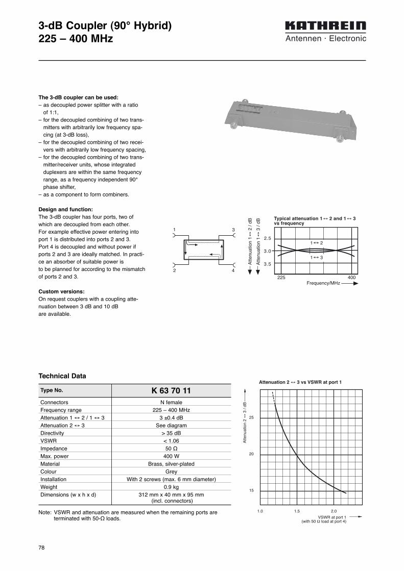
78
3-dB Coupler (90° Hybrid)225 – 400 MHz
Type No. K 63 70 11Connectors N femaleFrequency range 225 – 400 MHzAttenuation 1 ↔ 2 / 1 ↔ 3 3 ±0.4 dBAttenuation 2 ↔ 3 See diagramDirectivity > 35 dBVSWR < 1.06Impedance 50 ΩMax. power 400 WMaterial Brass, silver-platedColour GreyInstallation With 2 screws (max. 6 mm diameter)Weight 0.9 kgDimensions (w x h x d) 312 mm x 40 mm x 95 mm
(incl. connectors)
Note: VSWR and attenuation are measured when the remaining ports are terminated with 50-Ω loads.
Technical Data
The 3-dB coupler can be used:– as decoupled power splitter with a ratio
of 1:1,– for the decoupled combining of two trans-
mitters with arbitrarily low frequency spa-cing (at 3-dB loss),
– for the decoupled combining of two recei-vers with arbitrarily low frequency spacing,
– for the decoupled combining of two trans-mitter/receiver units, whose integratedduplexers are within the same frequencyrange, as a frequency independent 90°phase shifter,
– as a component to form combiners.
Design and function:The 3-dB coupler has four ports, two ofwhich are decoupled from each other. For example effective power entering intoport 1 is distributed into ports 2 and 3. Port 4 is decoupled and without power ifports 2 and 3 are ideally matched. In practi-ce an absorber of suitable power is to be planned for according to the mismatchof ports 2 and 3.
Custom versions:On request couplers with a coupling atte-nuation between 3 dB and 10 dB are available.
2.5
3.0
3.5
Frequency/MHz
1↔ 2
1↔ 3
400
Typical attenuation 1↔ 2 and 1↔ 3vs frequency
Atte
nuat
ion
1↔
3 /
dB
Atte
nuat
ion
1↔
2 /
dB
1 3
2 4
225
1.0 1.5 2.0
15
20
25
Atte
nuat
ion
2 ↔
3 /
dB
VSWR at port 1(with 50 Ω load at port 4)
Attenuation 2 ↔ 3 vs VSWR at port 1

79
Number of inputs 1Number of outputs 8Frequency range 225 – 400 MHzGain 3.0 dB ±1.5 dBNoise figure 4.0 dB +0.5 dB3rd order intercept point > 23 dBm (typ. 25 dBm)Isolation > 25 dB (typ. 30 dB) between any two outputsVSWR
Input < 1.4Output < 1.4
Impedance 50 ΩPower supply 230 V +10/–15%, 50 … 60 Hz and/or
11 … 48 V = floatingPower consumption < 9 W (230 V, 50 Hz)
< 20 W (11 … 48 V =)Temperature range –20 … +50 °CConnectors N femaleColour Front panel: GreyAttached hardware Power cable and 4 pin DC-connectorWeight 3.9 kgPacking size Approx. 540 mm x 105 mm x 410 mmDimensions (w x h x d) 483 mm x 44 mm x 250 mm, 19˝ drawer
Note: Unused outputs have to be terminated using a 50-Ω load in order to comply with the specifications.
Type No. 780 231
Receiver Multicoupler225 – 400 MHz, 8 Outputs
Technical Data
The use of the receiver multicoupler 780 231 isappropriate if several receivers are operatedsimultaneously at the same site. With this receivermulticoupler up to 8 receivers can be connected to one common antenna.This results in considerable savings for the antennasystem. The low noise figure and the excellent inter-modulation properties guarantee a high dynamic rangeand thereby improved receiving conditions. This is ofparticular significance in locations where transmitters are also operated next to receivers.
The receiver multicoupler consists of:– a low noise amplifier,– a power splitter,– a voltage supply.
The receiver multicoupler has an active redundancy dueto the two amplifier modules in parallel which are locatedin the low noise amplifier. This means that the receivermulticoupler still supplies all connected receivers even ifone of the amplifier modules fails. The signal levels in thiscase decrease by approximately 6 dB.Each amplifier module is designed for operation with itsown voltage supply of 230 V ~ or 11 … 48 V =.
Receiver multicoupler
Receiver Receiver Receiver Receiver Receiver
225 MHz 400
Example receiver multicoupler225 – 400 MHz
8 receivers
active redundantamplifier
decoupleddistributing
network
out-puts
Block diagram receiver multicoupler
Front view
Back view

80
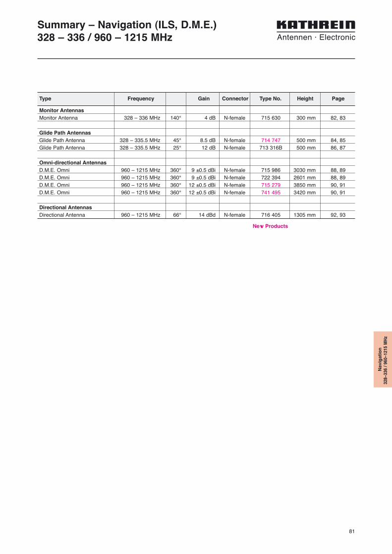
81
Monitor AntennasMonitor Antenna 328 – 336 MHz 140° 4 dB N-female 715 630 300 mm 82, 83
Glide Path AntennasGlide Path Antenna 328 – 335.5 MHz 45° 8.5 dB N-female 714 747 500 mm 84, 85Glide Path Antenna 328 – 335.5 MHz 25° 12 dB N-female 713 316B 500 mm 86, 87
Omni-directional AntennasD.M.E. Omni 960 – 1215 MHz 360° 9 ±0.5 dBi N-female 715 986 3030 mm 88, 89D.M.E. Omni 960 – 1215 MHz 360° 9 ±0.5 dBi N-female 722 394 2601 mm 88, 89D.M.E. Omni 960 – 1215 MHz 360° 12 ±0.5 dBi N-female 715 279 3850 mm 90, 91D.M.E. Omni 960 – 1215 MHz 360° 12 ±0.5 dBi N-female 741 495 3420 mm 90, 91
Directional AntennasDirectional Antenna 960 – 1215 MHz 66° 14 dBd N-female 716 405 1305 mm 92, 93
Summary – Navigation (ILS, D.M.E.)328 – 336 / 960 – 1215 MHz
Type Frequency Gain Connector Type No. Height Page
Nav
igat
ion
328–
336
/ 960
–121
5 M
Hz
New Products
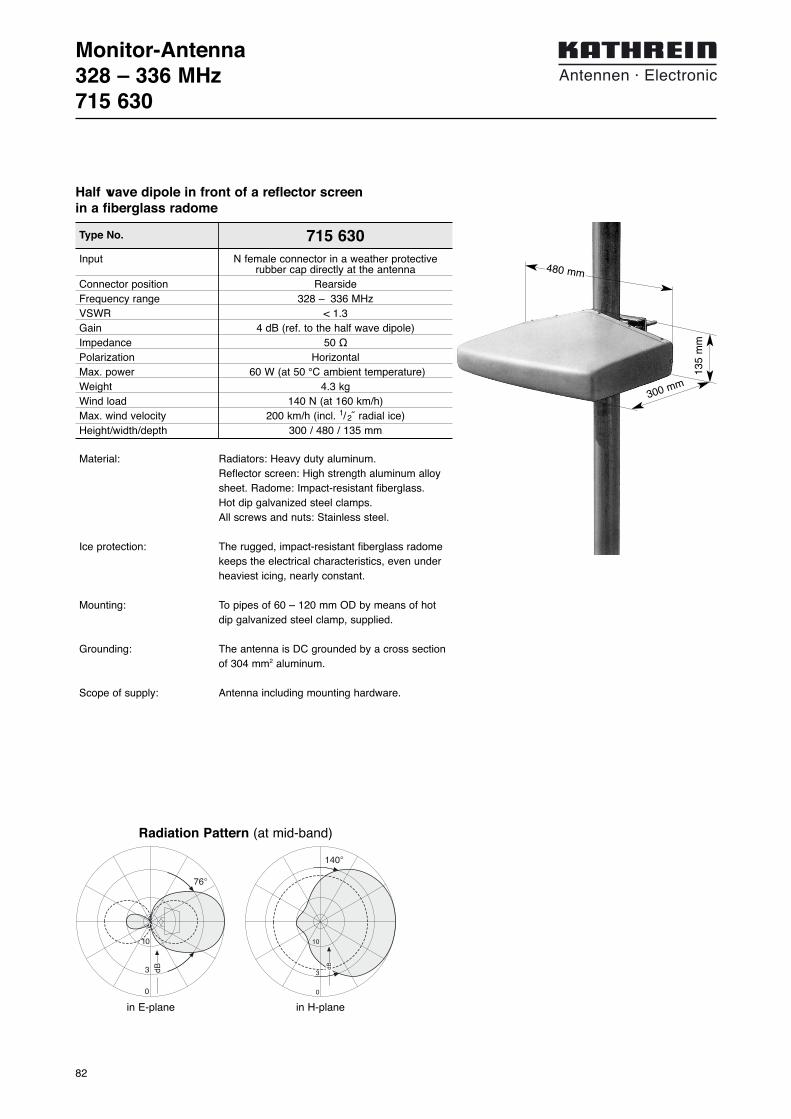
82
Monitor-Antenna328 – 336 MHz715 630
Type No. 715 630Input N female connector in a weather protective
rubber cap directly at the antennaConnector position RearsideFrequency range 328 – 336 MHzVSWR < 1.3Gain 4 dB (ref. to the half wave dipole)Impedance 50 ΩPolarization HorizontalMax. power 60 W (at 50 °C ambient temperature)Weight 4.3 kgWind load 140 N (at 160 km/h)Max. wind velocity 200 km/h (incl. 1/ 2˝ radial ice)Height/width/depth 300 / 480 / 135 mm
Material: Radiators: Heavy duty aluminum. Reflector screen: High strength aluminum alloysheet. Radome: Impact-resistant fiberglass. Hot dip galvanized steel clamps. All screws and nuts: Stainless steel.
Ice protection: The rugged, impact-resistant fiberglass radomekeeps the electrical characteristics, even underheaviest icing, nearly constant.
Mounting: To pipes of 60 – 120 mm OD by means of hotdip galvanized steel clamp, supplied.
Grounding: The antenna is DC grounded by a cross sectionof 304 mm2 aluminum.
Scope of supply: Antenna including mounting hardware.
10
3
0
140°
dB
Radiation Pattern (at mid-band)
in H-plane
76°
3 dB
10
0
in E-plane
Half wave dipole in front of a reflector screen in a fiberglass radome
300 mm
135
mm
480 mm

83
Mounting InstructionMonitor-Antenna715 630

84
Glide Path Antenna328 – 335.5 MHz714 747
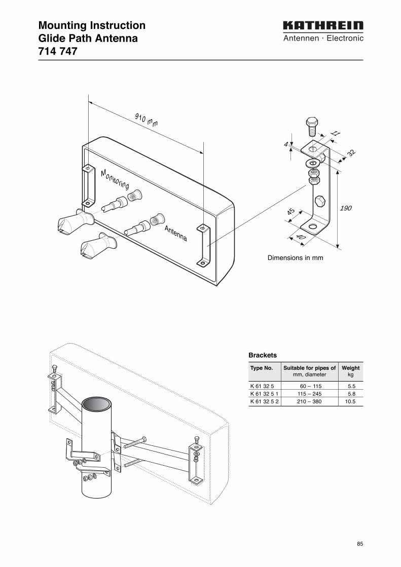
85
K 61 32 5 60 – 115 5.5K 61 32 5 1 115 – 245 5.8K 61 32 5 2 210 – 380 10.5
Mounting InstructionGlide Path Antenna714 747
11
32
45
4
40
910 mm
190
Dimensions in mm
Antenna
Monitoring
Type No. Suitable for pipes of Weightmm, diameter kg
Brackets
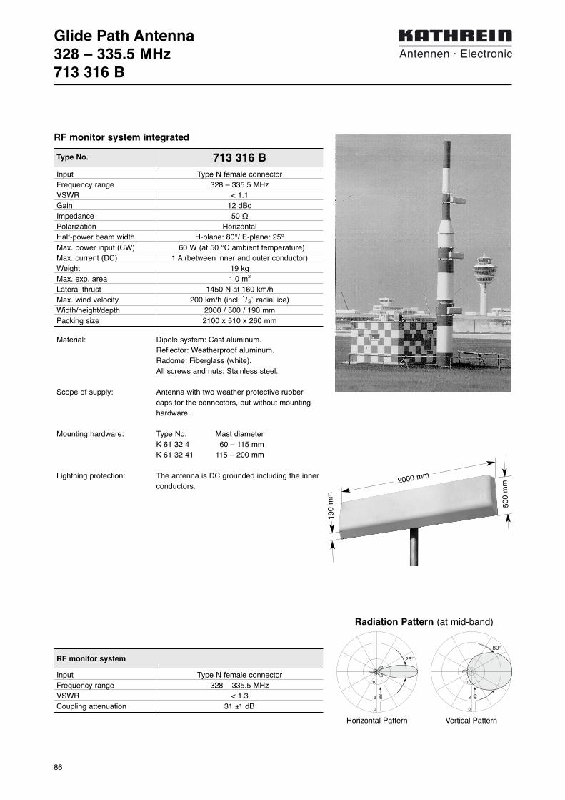
86
Glide Path Antenna328 – 335.5 MHz713 316 B
Material: Dipole system: Cast aluminum.Reflector: Weatherproof aluminum.Radome: Fiberglass (white).All screws and nuts: Stainless steel.
Scope of supply: Antenna with two weather protective rubber caps for the connectors, but without mountinghardware.
Mounting hardware: Type No. Mast diameterK 61 32 4 60 – 115 mmK 61 32 41 115 – 200 mm
Lightning protection: The antenna is DC grounded including the innerconductors.
Vertical PatternHorizontal Pattern
80°
3 dB
10
0
25°
3 dB
10
0
RF monitor system integrated
Type No. 713 316 BInput Type N female connectorFrequency range 328 – 335.5 MHzVSWR < 1.1Gain 12 dBdImpedance 50 ΩPolarization Horizontal Half-power beam width H-plane: 80°/ E-plane: 25°Max. power input (CW) 60 W (at 50 °C ambient temperature)Max. current (DC) 1 A (between inner and outer conductor)Weight 19 kgMax. exp. area 1.0 m2
Lateral thrust 1450 N at 160 km/hMax. wind velocity 200 km/h (incl. 1/ 2˝ radial ice)Width/height/depth 2000 / 500 / 190 mmPacking size 2100 x 510 x 260 mm
RF monitor system
Input Type N female connectorFrequency range 328 – 335.5 MHzVSWR < 1.3Coupling attenuation 31 ±1 dB
2000 mm
500
mm
190
mm
Radiation Pattern (at mid-band)
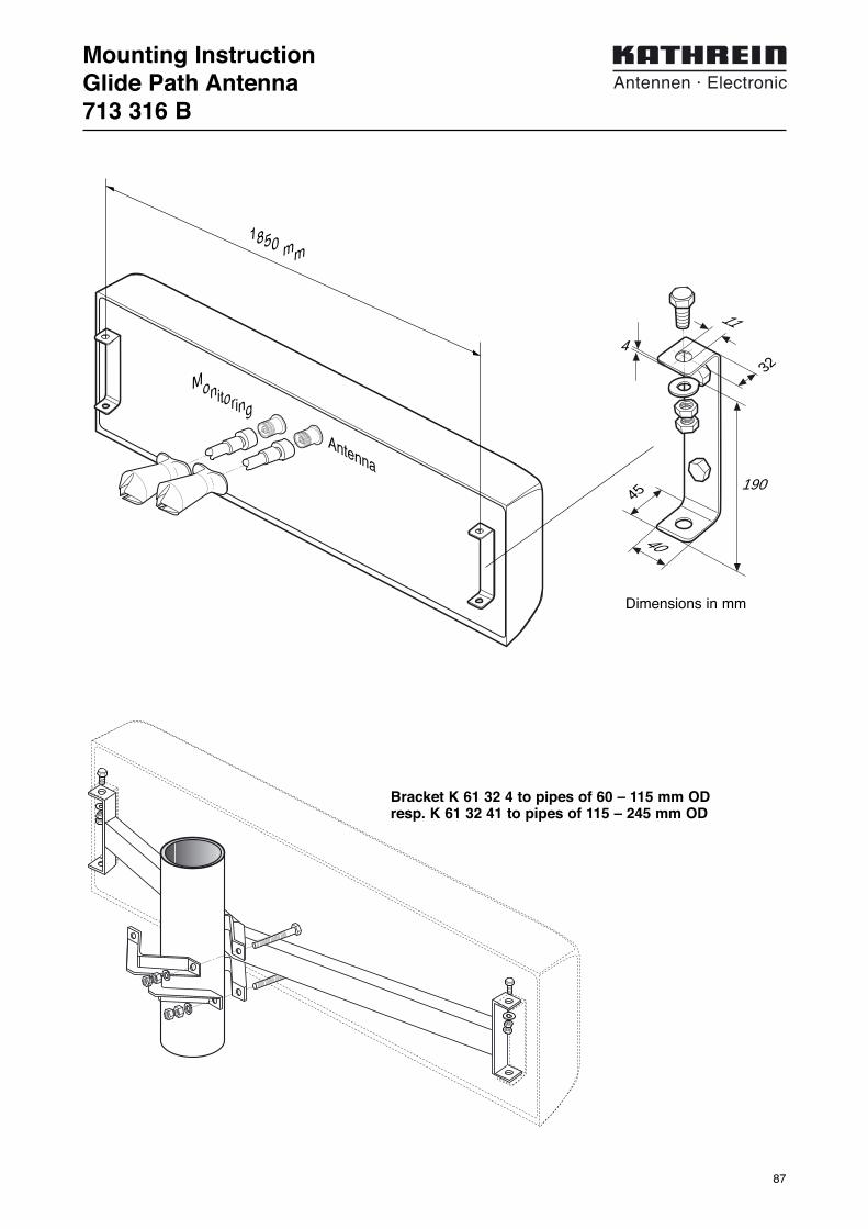
87
Mounting InstructionGlide Path Antenna713 316 B
11
32
45
4
40
1850 mm
190
Bracket K 61 32 4 to pipes of 60 – 115 mm ODresp. K 61 32 41 to pipes of 115 – 245 mm OD
Dimensions in mm
Antenna
Monitoring

88
D.M.E. Omnidirectional Gain Antenna960 – 1215 MHz715 986, 722 394
Type No. 715 986 722 394Obstruction light Yes NoInput (antenna/monitors) N femaleConnector position BottomFrequency range 960 – 1215 MHzBandwidth 255 MHzVSWR < 1.8 (antenna input)Gain 9 ±0.5 dBiImpedance 50 ΩHorizontal pattern Omnidirectional: Devitation from omni
better ±1.5 dBVertical pattern uptilt 3 ±0.5°Coupling attention 25 ±3 dB (antenna/monitor probes)R. F. peak power 10 kW, modulated as per ICAO recommendationPolarization VerticalTemperature range –40 to +60 °C ambientWeight 28 kg 21 kgWind load 400 N 270 N
(at 150 km/h with 12 mm radial ice)Max. wind velocity 150 km/h 200 km/h
(incl. 12 mm radial ice)Radome diameter 86 mm
Material: Dipoles, decoupling elements, supporting tubeand transformer: High quality brass.Base: Weather-resistant aluminum.Radome: Fiberglass, colour: Grey.All screws and nuts: Stainless steel.
Mounting: To pipes of 60 – 62 mm OD by means of moun-ting clamps, supplied.
Grounding: The antenna is DC grounded by a cross sectionof 98 mm2 brass.
10
3
0
dB
Radiation Pattern (at mid-band)
Vertical Pattern
dB
10
3
0
Horizonal Pattern
The antenna consists of a number of identical, decoupled half-wave dipoles,phase-feeding cables and transformer.Each dipole is mounted onto a central supporting brass tube. The horizontalpattern is obtained by the circular characteristic of the single dipole, the verticalpattern varying phase and distance of the single dipoles.All metal parts are DC grounded and, therefore, widely immune to damage from lightning. The top of the antenna is fitted with a dual obstruction light (type no. 715 986).Two antenna monitor probes are located inside the fiberglass tube. All feedlinesand monitor cables descend inside the supporting brass tube.

89
Mounting InstructionD.M.E. Omnidirectional Gain Antenna715 986, 722 394
60
ø62
M 12
M 2
M 1OLA
MS 310 2 R-12s-3p
5/8" 24G NEF
140
3080
656
3030
1945
956
ø 8
6E
lect
r. ce
nter
obst
ruct
ion
light
2 x
60 W
att
M12
obst
ruct
ion
light
2 x
60 W

90
D.M.E. Omnidirectional Gain Antenna960 – 1215 MHz715 279, 741 495
Type No. 715 279 741 495Obstruction light Yes NoInput (antenna/monitors) N femaleConnector position BottomFrequency range 960 – 1215 MHzBandwidth 255 MHzVSWR < 1.8 (antenna input)Gain 12 ±0.5 dBiImpedance 50 ΩHorizontal pattern Omnidirectional: Devitation from omni
better ±1.5 dBVertical pattern uptilt 3 ±0.5°Coupling attention 25 ±3 dB (antenna/monitor probes)R. F. peak power 10 kW, modulated as per ICAO recommendationPolarization VerticalTemperature range –40 to +60 °C ambientWeight 33 kg 26 kgWind load 480 N 350 N
(at 150 km/h with 12 mm radial ice)Max. wind velocity 150 km/h 200 km/h
(incl. 12 mm radial ice)Radome diameter 86 mm
Material: Dipoles, decoupling elements, supporting tubeand transformer: High quality brass.Base: Weather-resistant aluminum.Radome: Fiberglass, colour: Grey.All screws and nuts: Stainless steel.
Mounting: To pipes of 60 – 62 mm OD by means of moun-ting clamps, supplied.
Grounding: The antenna is DC grounded by a cross sectionof 98 mm2 brass.
10
3
0
dB
Radiation Pattern (at mid-band)
Vertical Pattern
dB
10
3
0
Horizonal Pattern
The antenna consists of a number of identical, decoupled half-wave dipoles,phase-feeding cables and transformer.Each dipole is mounted onto a central supporting brass tube. The horizontalpattern is obtained by the circular characteristic of the single dipole, the verticalpattern varying phase and distance of the single dipoles.All metal parts are DC grounded and, therefore, widely immune to damage from lightning. The top of the antenna is fitted with a dual obstruction light (type no. 715 279).Two antenna monitor probes are located inside the fiberglass tube. All feedlinesand monitor cables descend inside the supporting brass tube.

91
Mounting InstructionD.M.E. Omnidirectional Gain Antenna715 279, 741 495
60
ø62
M 12
M 2
M 1OLA
MS 310 2 R-12s-3p
5/8" 24G NEF
140
3080
656
3850
2764
1366
ø 8
6E
lect
r. ce
nter
obst
ruct
ion
light
2 x
60 W
att
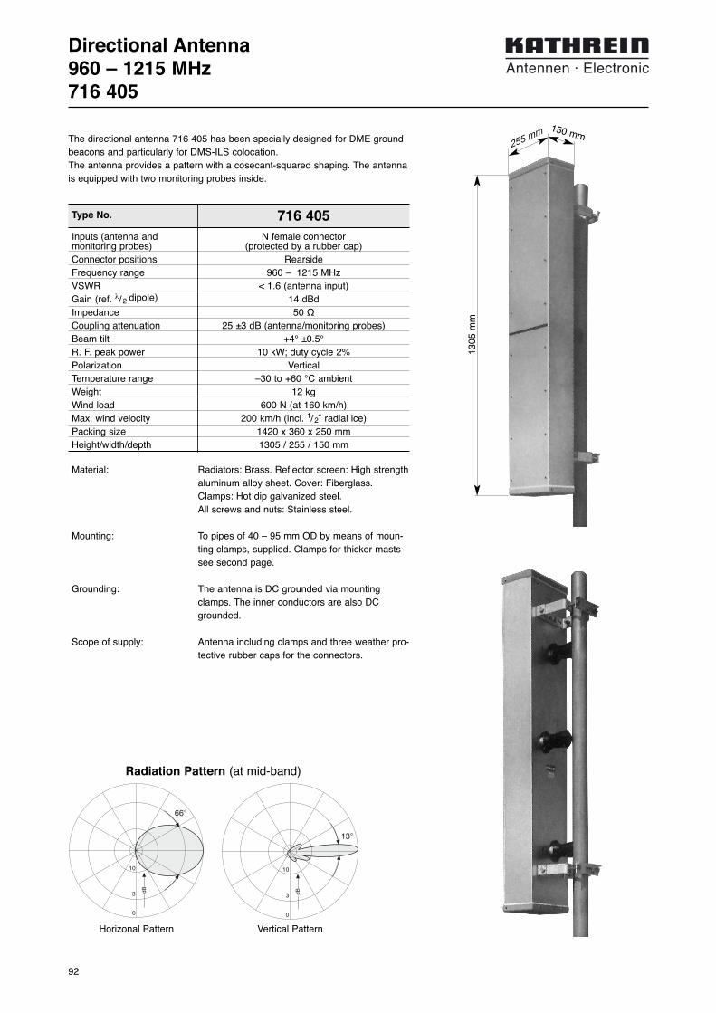
92
Directional Antenna960 – 1215 MHz716 405
Type No. 716 405Inputs (antenna and N female connectormonitoring probes) (protected by a rubber cap)Connector positions RearsideFrequency range 960 – 1215 MHzVSWR < 1.6 (antenna input)Gain (ref. λ/ 2 dipole) 14 dBdImpedance 50 ΩCoupling attenuation 25 ±3 dB (antenna/monitoring probes)Beam tilt +4° ±0.5°R. F. peak power 10 kW; duty cycle 2%Polarization VerticalTemperature range –30 to +60 °C ambientWeight 12 kgWind load 600 N (at 160 km/h)Max. wind velocity 200 km/h (incl. 1/ 2˝ radial ice)Packing size 1420 x 360 x 250 mmHeight/width/depth 1305 / 255 / 150 mm
Material: Radiators: Brass. Reflector screen: High strengthaluminum alloy sheet. Cover: Fiberglass. Clamps: Hot dip galvanized steel. All screws and nuts: Stainless steel.
Mounting: To pipes of 40 – 95 mm OD by means of moun-ting clamps, supplied. Clamps for thicker mastssee second page.
Grounding: The antenna is DC grounded via mountingclamps. The inner conductors are also DCgrounded.
Scope of supply: Antenna including clamps and three weather pro-tective rubber caps for the connectors.
10
3
0
13°
dB
Radiation Pattern (at mid-band)
Vertical Pattern
10
3
0
66°
dB
Horizonal Pattern
The directional antenna 716 405 has been specially designed for DME groundbeacons and particularly for DMS-ILS colocation.The antenna provides a pattern with a cosecant-squared shaping. The antennais equipped with two monitoring probes inside.
1305
mm
150 mm255 mm

93
Mounting InstructionDirectional Antenna716 405
Accessories (order separately)
K 61 14 02 2 clamps Mast: 60 – 115 mm diameter 1.6 kg 1K 61 14 03 2 clamps Mast: 116 – 210 mm diameter 4.0 kg 1K 61 14 04 2 clamps Mast: 210 – 380 mm diameter 7.2 kg 1
Type No. Description RemarksWeight Units perapprox. antenna
K 61 14 03
TOP
M1
A
M2
M1, M2 = connectorsmonitoring system
A = connector RF input
required metric wrenches: 17 mm

94
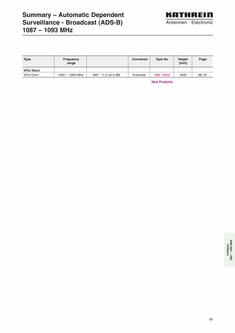
95
VPol OmniVPol Omni 1087 – 1093 MHz 360° 11.5 ±0.5 dBi N-female 880 10002 3420 96, 97
Summary – Automatic Dependent Surveillance - Broadcast (ADS-B) 1087 – 1093 MHz
Type Frequency Connector Type No. Height Pagerange [mm]
Co
llisi
on
1087
– 1
093
MH
z
New Products

96
Type No. 880 10002Frequency range 1087 – 1093 MHz
Polarization Vertical
Gain 11.5 ±0.5 dBi
Impedance 50 Ω
VSWR < 1.8 (antenna input)
Horizontal pattern Omnidirectional: Deviation from omnibetter ±1.5 dB
Vertical pattern uptilt 2° ±0.5°
Coupling attention 25 ±3 dB (antenna/monitor probes)
R. F. peak power 1 kW, modulated as per ICAO recommendation
Temperature range –55 to +70 °C ambient
Material: Dipoles, decoupling elements, supporting tubeand transformer: High quality brass.Base: Weather-resistant aluminum.Radome: Fiberglass, colour: Grey.All screws and nuts: Stainless steel.
Mounting: To pipes of 60 – 62 mm OD by means of moun-ting clamps, supplied.
Grounding: The antenna is DC grounded by a cross sectionof 98 mm2 brass.
10
3
0
dB
Radiation Pattern (at mid-band)
Vertical Pattern
dB
10
3
0
Horizonal Pattern
The antenna consists of a number of identical, decoupled half-wave dipoles,phase-feeding cables and transformer.Each dipole is mounted onto a central supporting brass tube. The horizontalpattern is obtained by the circular characteristic of the single dipole, the verticalpattern varying phase and distance of the single dipoles.All metal parts are DC grounded and, therefore, widely immune to damage from lightning.Two antenna monitor probes are located inside the fiberglass tube. All feedlinesand monitor cables descend inside the supporting brass tube.
VPol Omni 1087–1093 360° 11.5dBi
VPol Omnidirectional AntennaVertical Polarization
1087–1093
V
Input (antenna/monitors) N female
Connector position Bottom
Weight 26 kg
Wind load 350 N(at 150 km/h with 12 mm radial ice)
Max. wind velocity 200 km/h
Packing size 3500 x 200 x 220 mm
Height 3420 mm
Radome diameter 86 mm
Mechanical specifications

97
Mounting InstructionVPol Omnidirectional Antenna880 10002
60
ø62
M 12
M 2
M 1
A
5/8" 24G NEF
140
3080
656
2764
1366
ø 8
6E
lect
r. ce
nter
M12

98
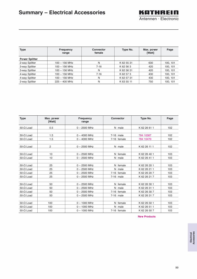
99
Power Splitter2-way Splitter 100 – 156 MHz N K 62 55 31 630 100, 1013-way Splitter 100 – 156 MHz 7-16 K 62 56 3 420 100, 1013-way Splitter 100 – 156 MHz N K 62 56 31 420 100, 1014-way Splitter 100 – 156 MHz 7-16 K 62 57 3 430 100, 1014-way Splitter 100 – 156 MHz N K 62 57 31 430 100, 1012-way Splitter 225 – 400 MHz N K 63 55 11 750 100, 101
Summary – Electrical Accessories
Type Frequency Connector Type No. Max. power Pagerange female [Watt]
50-Ω Load 0.5 0 – 2500 MHz N male K 62 26 61 1 102
50-Ω Load 1.5 0 – 4000 MHz 7-16 male 784 10367 10250-Ω Load 1.5 0 – 4000 MHz 7-16 female 784 10470 102
50-Ω Load 2 0 – 2500 MHz N male K 62 26 11 1 102
50-Ω Load 10 0 – 2500 MHz N female K 62 26 40 1 10350-Ω Load 10 0 – 2500 MHz N male K 62 26 41 1 103
50-Ω Load 25 0 – 2500 MHz N female K 62 26 20 1 10350-Ω Load 25 0 – 2500 MHz N male K 62 26 21 1 10350-Ω Load 25 0 – 2500 MHz 7-16 female K 62 26 20 7 10350-Ω Load 25 0 – 2500 MHz 7-16 male K 62 26 21 7 103
50-Ω Load 50 0 – 2500 MHz N female K 62 26 30 1 10350-Ω Load 50 0 – 2500 MHz N male K 62 26 31 1 10350-Ω Load 50 0 – 2500 MHz 7-16 female K 62 26 30 7 10350-Ω Load 50 0 – 2500 MHz 7-16 male K 62 26 31 7 103
50-Ω Load 100 0 – 1000 MHz N female K 62 26 50 1 10350-Ω Load 100 0 – 1000 MHz N male K 62 26 51 1 10350-Ω Load 100 0 – 1000 MHz 7-16 female K 62 26 50 7 103
Type Max. power Frequency Connector Type No. Page[Watt] range
Ele
ctri
cal
Acc
esso
ries
New Products

100
Power Splitter100 – 156 MHz / 225 – 400 MHz
Frequency For Length L Max. Type No. for female connectionrange connecting approx. power *) (equipment and antenna side)MHz ... antennas mm W 7-16 N
100 – 156 2 660 630 K 62 55 313 720 420 K 62 56 3 K 62 56 314 760 430 K 62 57 3 K 62 57 31
225 – 400 2 870 750 K 63 55 11*) at 50 °C ambient temperature
Impedance: 50 Ω
Input and output: N female or 7-16 female connector.
VSWR: < 1.15
Insertion loss: < 0.05 dB (of the transformation line)
Material: Protective case on the antenna side: Cast aluminum.Weather protection on the equipment side: UV-resistantelastomere.Transformation tube: Aluminum and brass.All parts are protected with paint.All screws and nuts: Stainless steel.
Mounting: On tubular masts of 60 – 320 mm by means of stainlesssteel tightening band 1020 x 20 x 1 mm, supplied.Transformers with a total length of more than 700 mm aredelivered with a supporting clamp.
Example of 4-way antenna transformer
Power Splitters for low-loss connection of several antennas:
Ant.1 Ant.2 Ant.3 Ant.4
K K K K
Equipment
K: 50 Ω-cablesof the sameelectrical length
160 mm
160 mm
L
210
mm
K: 50-Ω cablesof the sameelectrical length

101
Mounting InstructionPower SplitterK 62 55 31, K 62 56 3., K 62 57 3., K 63 55 11
1 2
3 4

102
Connector N maleFrequency range 0 – 2500 MHzVSWR 0 – 1000 MHz < 1.08VSWR1000 – 2000 MHz < 1.15VSWR2000 – 2500 MHz < 1.20Application IndoorWeight 40 gPacking size 90 mm x 60 mm x 25 mmDimensions 33 mm / 21 mm diameter
Load50 Ω
50-Ω loads are suited as absorbers for small and medium power.
They are used:– as termination for transmitters or amplifiers used for testing,
measuring or tuning,– as termination for circulators, directional couplers, hybrid
ring junctions and decoupled power splitters.
Special features of the loads are:– very low VSWR within a wide frequency range,– high stability and RF shielding due to the closed aluminium
construction,– arbitrary installation position because of convectional
cooling,– 50 W and 100 W models can be installed on front or rear
panels of electrical equipment for heat dissipation.
Type No. K 62 26 61 1
0.5 Watt *)
Type No. 784 10367 784 10470Connector 7-16 male 7-16 femaleFrequency range 0 – 4000 MHzVSWR 0 – 2000 MHz < 1.10
VSWR 2000 – 4000 MHz < 1.30IP rating IP65Application OutdoorWeight 120 gPacking size Approx. 50 mm x 90 mm x 100 mmDimensions 40 mm / 32 mm diameter 42 mm / 29 mm diameter
1.5 Watt *)
K 62 26 61 1
784 10367
Type No. K 62 26 11 1Connector N maleFrequency range 0 – 2500 MHzVSWR 0 – 1000 MHz < 1.08
VSWR 1000 – 2000 MHz < 1.15VSWR 2000 – 2500 MHz < 1.20Application IndoorWeight 40 gPacking size 90 mm x 60 mm x 25 mmDimensions 30 mm / 21 mm diameter
2 Watt *)
K 62 26 11 1
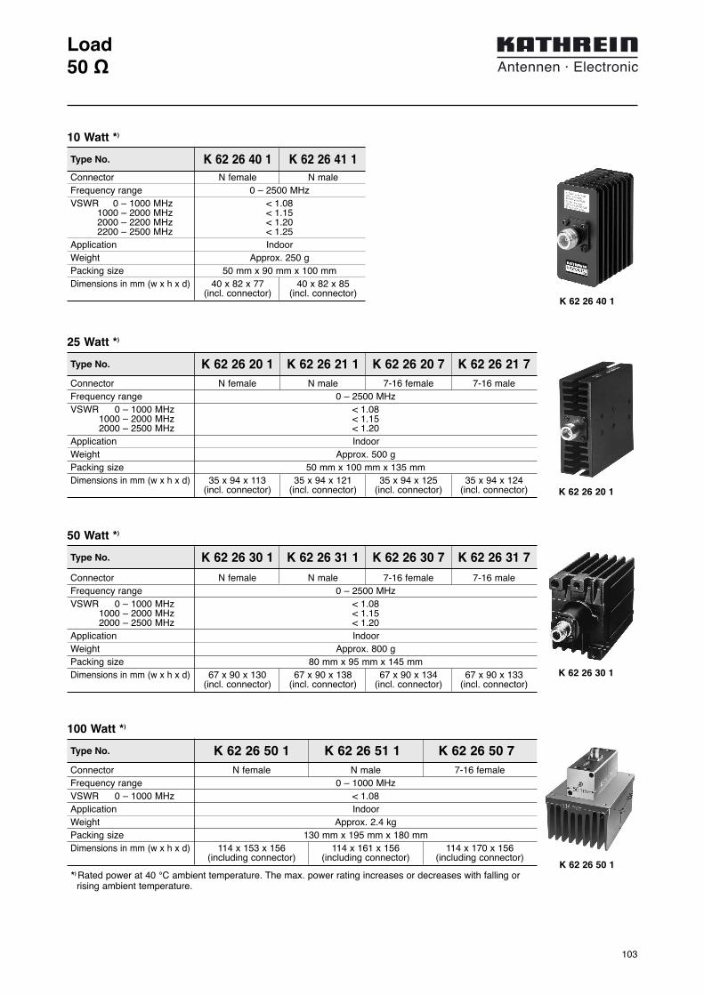
103
Connector N female N maleFrequency range 0 – 2500 MHzVSWR 0 – 1000 MHz < 1.08
V 1000 – 2000 MHz < 1.15VSW R2000 – 2200 MHz < 1.20VSW R2200 – 2500 MHz < 1.25Application IndoorWeight Approx. 250 gPacking size 50 mm x 90 mm x 100 mmDimensions in mm (w x h x d) 40 x 82 x 77 40 x 82 x 85
(incl. connector) (incl. connector)
Load50 Ω
Type No. K 62 26 30 1 K 62 26 31 1 K 62 26 30 7 K 62 26 31 7Connector N female N male 7-16 female 7-16 maleFrequency range 0 – 2500 MHzVSWR 0 – 1000 MHz < 1.08VSWR1000 – 2000 MHz < 1.15VSWR2000 – 2500 MHz < 1.20Application IndoorWeight Approx. 800 gPacking size 80 mm x 95 mm x 145 mmDimensions in mm (w x h x d) 67 x 90 x 130 67 x 90 x 138 67 x 90 x 134 67 x 90 x 133
(incl. connector) (incl. connector) (incl. connector) (incl. connector)
50 Watt *)
Type No. K 62 26 50 1 K 62 26 51 1 K 62 26 50 7Connector N female N male 7-16 femaleFrequency range 0 – 1000 MHzVSWR 0 – 1000 MHz < 1.08Application IndoorWeight Approx. 2.4 kgPacking size 130 mm x 195 mm x 180 mmDimensions in mm (w x h x d) 114 x 153 x 156 114 x 161 x 156 114 x 170 x 156
(including connector) (including connector) (including connector)
*) Rated power at 40 °C ambient temperature. The max. power rating increases or decreases with falling or rising ambient temperature.
100 Watt *)
Type No. K 62 26 20 1 K 62 26 21 1 K 62 26 20 7 K 62 26 21 7Connector N female N male 7-16 female 7-16 maleFrequency range 0 – 2500 MHzVSWR 0 – 1000 MHz < 1.08VSWR1000 – 2000 MHz < 1.15VSWR2000 – 2500 MHz < 1.20Application IndoorWeight Approx. 500 gPacking size 50 mm x 100 mm x 135 mmDimensions in mm (w x h x d) 35 x 94 x 113 35 x 94 x 121 35 x 94 x 125 35 x 94 x 124
(incl. connector) (incl. connector) (incl. connector) (incl. connector)
25 Watt *)
K 62 26 30 1
K 62 26 50 1
K 62 26 20 1
Type No. K 62 26 40 1 K 62 26 41 1
10 Watt *)
K 62 26 40 1

104

105
Bracket K 61 33 3 500 mm 55 – 105 mm 106Bracket 716 192 500 mm 105 – 265 mm 106Bracket K 61 33 4 1000 mm 55 – 105 mm 106Bracket 713 645 1000 mm 105 – 265 mm 106
Summary – Mechanical Accessories
Type Type No. Distance to mast Mast diameter Page
Side mounting brackets for Omnidirectional Antennas
Guy-wire adapter 742 363 107
Type Type No. Page
Guy-wire adapter
Mec
han
ical
Acc
esso
ries
New Products
New Products

106
Weight 6.6 kg 13.7 kg 6 kgDistance A:
min. 125 mm 100 mmmax. 680 mm 240 mm
Suitable for antennas with mounting kit to pipe masts of20 – 54 mm 30 – 90 mm 50 – 94 mm
diameter diameter
Attachment By means of mounting kit (supplied) to pipes of55 mm – 105 mm 40 – 105 mm
diameter diameter
Material Hot-dip galvanized steel.Wind load 45 N 100 N 65 N
(at 150 km/h) (at 150 km/h) (at 150 km/h)
L 30 x 4
100 to240 mm
Pipe70 x 4 mmfree length250 mm
L 30 x 4
245 mm
1
2
AccessoriesStand-off Brackets
1015 mm
515 mm
K 61 33 3
K 61 33 4
95
pipe diameter
44.5 x 2.6 mm
pipe diameter
44.5 x 2.6 mm
When mounted to the tip of a mast, the antennas described in this catalogue radiate horizontally ina circular fashion. However, they can also be mounted laterally to a mast by using an extensionbracket. Depending on the spacing and the mast diameter, various types of radiation patterns canbe achieved. (For further information please see the “Technical Information” part of our catalogue on pages 95 and 96)
Weight 2 kg 7 kg 3.2 kg 8.5 kg
Distance A: 500 mm 1000 mm
Suitable for antennas with amaximum wind load of 215 N (at 150 km/h) 85 N (at 150 km/h)
Suitable for antennas with mounting kit to pipe masts of 20 – 54 mm diameter.
Attachment By means of mounting kit (supplied)to pipes of diameter:
55 mm – 105 mm – 55 mm – 105 mm –105 mm 265 mm 105 mm 265 mm
Material Hot-dip galvanized steel.
Wind load 36 N (at 150 km/h) 60 N (at 150 km/h)
Type No. K 61 33 3 716 192 K 61 33 4 713 645
Bracket with fixed spacing
Bracket with adjustable spacing A
Implementation Stand-off Double stand-offfig. A fig. B fig. C
Type No. K 61 33 11 K 61 33 21 737 398
40 x 40 mm
740 mm
125 to680 mm
Pipe48.3 x 2.6 mm(100 mm length)free length65 mm
40 x 40 mm
125 to680 mm
Pipe76.1 x 2.6 mmfree length180 mm
40 x 40 mm
740 mm
1
2
fig. A fig. B fig. C
A
D
A: 125 … 680 mmD: 450 mm
Double Bracket
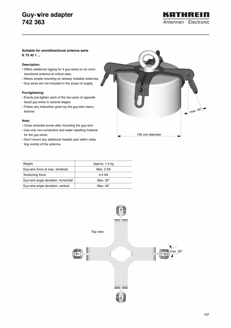
107
Guy-wire adapter742 363
Weight Approx. 1.2 kg
Guy-wire force at max. windload Max. 3 kN
Tensioning force 0.4 kN
Guy-wire angle deviation, horizontal Max. 30°
Guy-wire angle deviation, vertical Max. 45°
max. 30°
Top view
max. 45°
Suitable for omnidirectional antenna serie K 75 40 1 ...
Description:
• Offers additional rigging for 4 guy-wires on an omni-
directional antenna at critical sites.
• Allows simple mounting on already installed antennas.
• Guy-wires are not included in the scope of supply.
Pre-tightening:
• Evenly pre-tighten each of the two pairs of opposite
faced guy-wires in several stages.
• Follow any instruction given by the guy-wire manu-
facturer.
Note:
• Close schackle-screw after mounting the guy-wire.
• Use only non-conductive and water repelling material
for the guy-wires.
• Don’t mount any additional metallic part within radia-
ting vicinity of the antenna.
195 mm diameter

Professional Antennas
Professional Antennas areavailable for virtually all operating conditionsencountered in actual practice. They willcontinue to operate even under severe weatherconditions and can withstand extremely highwind velocities. In addition to corrosion-resistantmaterials, sturdy design and electrical andmechanical quality control testing of each andevery antenna, a safety factor of 2 againstmechanical failure is your guarantee ofmaximum reliability and years of maintenance-free operation.
For this reason, we guarantee the full service-ability of our antennas for at least 5 years.However experience has shown that theantennas require absolutely no mainte-nance whatsoever for up to 15 years andlonger.This catalogue includes standard antennasand accessories for antenna systems forground to air communications and navigation.In addition, we also manufacture many typesof special models, matched to your specifi-cations or specific conditions.
KATHREIN-Werke KG . Phone +49 80 31 184-0 . Fax +49 80 31 184-494Anton-Kathrein-Straße 1 – 3 . P.O. Box 10 04 44 . D-83004 Rosenheim . Germany
Internet: http://www.kathrein.de
9981
0.66
9/11
07/2
/ZW
/PF
Sub
ject
to
alte
ratio
n.
Airport Munich II


