Pneumatic cylinders aerospace climate control electromechanical filtration fluid & gas handling hydraulics pneumatics process control sealing & shielding Series P1E According to ISO and VDMA Cylinder diameters 160 and 200 mm Catalogue PDE2580TCUK November 2010
Transcript
Pneumatic cylinders
aerospaceclimate control electromechanicalfiltrationfluid & gas handlinghydraulicspneumaticsprocess controlsealing & shielding
Series P1EAccording to ISO and VDMACylinder diameters 160 and 200 mmCatalogue PDE2580TCUK November 2010
2
P1E Cylinders
08.03
www.parker.com/euro_pneumatic
SALE CONDITIONSThe items described in this document are available for sale by Parker Hannifin Corporation, its subsidiaries or its authorized distributors. Any sale contract entered into by Parker will be governed by the provisions stated in Parker’s standard terms and conditions of sale (copy available upon request).
WARNING
FAILURE OR IMPROPER SELECTION OR IMPROPER USE OF THE PRODUCTS AND/OR SYSTEMS DESCRIBED HEREIN OR RELATED ITEMS CAN CAUSE DEATH, PERSONAL INJURY ANDPROPERTY DAMAGE.This document and other information from Parker Hannifin Corporation, its subsidiaries and authorized distributors provide product and/or system options for further investigation by users having technical expertise. It is important that you analyze all aspects of your application and review the information concerning the product or system in the current product catalog. Due to the variety of operating conditions and applications for these products or systems, the user, through its own analysis and testing, is solely responsible for making the final selection of the products and systems and assuring that all performance, safety and warning requirements of the application are met. The products described herein, including without limitation, product features, specifications, designs, availability and pricing, are subject to change by Parker Hannifin Corporation and its subsidiaries at any time without notice.
NoteAll technical data in this catalogue are typical data only.Air quality is essential for maximum cylinder service life (see ISO 8573).
ImportantBefore attempting any external or internal work on the cylinder or any connected components, make sure the cylinder is vented and dis connect the air supply in order to ensure isolation of the air supply.
Features Air Hydraulic Electro cylinder cylinder mechanical actuators
Overload safe *** *** *
Easy to limit force *** *** *
Easy to vary speed *** *** *
Speed *** ** **
Reliability *** *** ***
Robustness *** *** *
Installation cost *** * **
Ease of service *** ** *
Safety in damp environments *** *** *
Safety in explosive atmospheres *** *** *
Safety risk with electrical installations *** *** *
Risk of oil leak *** * ***
Clean, hygienic *** ** *
Standardised measurements *** *** *
Service life *** *** *
Hydraulic system required *** * ***
Weight ** ** **
Purchase price *** ** *
Power density ** *** *
Noise level during operation ** *** **
High force for size ** *** *
Positioning possibilities * *** ***
Total energy consumption * ** ***
Service interval * ** ***
Compressor capacity required * *** ***
* = good, **=average, ***=excellent
3
P1E Cylinders
08.03
www.parker.com/euro_pneumatic
Contents PageP1E Series, general .......................................................................................4Cylinder forces ...............................................................................................6Main data ........................................................................................................6Material specification .....................................................................................6Working medium, air quality ..........................................................................6Cushioning characteristics .............................................................................6Order key ........................................................................................................7Stroke length ..................................................................................................7Order code standard strokes double-acting P1E-T .......................................7Guide for selecting suitable tubing ................................................................8Dimensions ...................................................................................................10Cylinder mountings .................................................................................11-13Sensors ...................................................................................................14-16Connecting cables with one connector ........................................................17Male connectors for connecting cables .......................................................17Ready to use connecting cables with connectors at each end ...................17Connection block Valvetronic 110 ................................................................18Repair kits .....................................................................................................19Grease for P1E .............................................................................................19
4
P1E Cylinders
08.03
www.parker.com/euro_pneumatic
ISO Cylinders – P1EThe P1E Series of I.S.O. cylinders are precision made to the most exacting standards to provide the finest pneumatic cylinders available with the widest choice of options.
Installation dimensions according to international ISO/VDMA standardsThe new P1E complies with the current ISO 6431, ISO 15552, VDMA 24562 and AFNOR installation dimension standards. For customer reassurance world-wide.
High qualityAs with our other products, the P1E has been developed with quality in all aspects – specification, design, plan-ning, purchasing, production, distribution and service.We have been certified under the ISO 9001 QA standard since 1992. Quality in all our products and services is our prime aim.
Adaptability for use with electronicsP1E Cylinders are equipped as standard with magnetic pistons for position sensing. A full range of sensors enables the cylinders to be integrated into the most advanced automation systems. The sensors can be fitted at any position along the cylinder stroke.
DesignIn the development of P1E cylinders, great emphasis was placed on the importance of long service life, and operation with unlubricated air, characteristics essential for applications in demanding environments.
Long service lifeProven sealing systems and pre-lubricated bearings, together with surface smoothness and precise toler-ances in all constituent parts, provide long, safe and reliable service life.
Acetal wear strip on piston aids smooth operation. A magnetic strip is housed within the wear strip as standard.
High fibre nitrile piston rod seal and poly-urethane wiper ring.
Combined cushion/ non return seal for fast breakaway speed of the piston.
Anodised aluminium cylinder bore for high strength and low weight
Die cast aluminium end plates.
Retained cushion adjusting screw allows a high degree of cushion control and will not blow out during adjustment.
Stainless steel piston rod as standard.
Spigots on front and rear plates ensures precise location of mounting.
Oil retaining bronze bearing ensures extreme piston rod accuracy.
Extra long acetal cushion sleeves for improved life and long cushion length.
Polyurethane piston seals prelubricated for outstanding non-lube operation.
5
P1E Cylinders
08.03
www.parker.com/euro_pneumatic
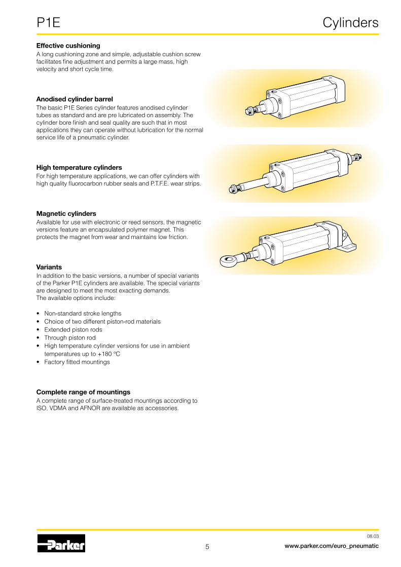
Effective cushioningA long cushioning zone and simple, adjustable cushion screw facilitates fine adjustment and permits a large mass, high velocity and short cycle time.
Anodised cylinder barrelThe basic P1E Series cylinder features anodised cylinder tubes as standard and are pre lubricated on assembly. The cylinder bore finish and seal quality are such that in most applications they can operate without lubrication for the normal service life of a pneumatic cylinder.
High temperature cylindersFor high temperature applications, we can offer cylinders with high quality fluorocarbon rubber seals and P.T.F.E. wear strips.
Magnetic cylindersAvailable for use with electronic or reed sensors, the magnetic versions feature an encapsulated polymer magnet. This protects the magnet from wear and maintains low friction.
VariantsIn addition to the basic versions, a number of special variants of the Parker P1E cylinders are available. The special variants are designed to meet the most exacting demands.The available options include:
Main data: P1ECylinder Cylinder Piston rod Total mass Mass moving parts Air con- Conn. beteckning bore area dia. area thread at 0 mm Supplement at 0 mm Supplement sump- thread stroke per 10 mm stroke per 10 mm tion stroke stroke mm cm2 mm cm2 kg kg kg kg litre
1)Free air consumption per 10 mm stroke for a double stroke at 6 bar
Material specificationPiston rod Stainless steel, X 10 CrNiS 18 9Piston rod seal PolyurethanePiston rod bearing Oil Retaining BronzeEnd cover Black anodised aluminiumTie Rods Zinc Plated SteelTie Rod Nuts Zinc Plated SteelO-ring, internal Nitrile rubber, NBRCylinder barrel HardanodisedaluminiumPiston AluminiumPiston seal PolyurethanePiston bearing PolyurethaneMagnetic ring Plastic bound magnetic material
Variants:
High-temperature version, type F:
Piston rod seal Fluorocarbon rubber, FPMPiston seal Fluorocarbon rubber, FPMO-rings Fluorocarbon rubber, FPM
Operation data Working pressure Max 10 barWorking temperature max +70 °C min –10 °C
Hightempversion max+180°C min 0 °C
Greased for life, does not normally need additional lubrication. If extra lubrication is given, this must always be continued.
Cushioning characteristicsThe diagram below is used for dimensioning of cylinders re-lated to the cushioning capacity. The maximum cushioning capacity shown in the diagram assumes the following:
The load is the sum of internal and external friction, plus any gravitational forces. At high relative load (pressure drop excee-ding 1 bar), we recommend that for any given speed, the mass should be reduced by a factor of 2.5, or for a given mass, the speed should be reduced by a factor of 1.5. This is in relation to the maximum performance given in the diagram
Speed [m/s]
Mass [kg]
Note!Select a theoretical force 50-100% larger than the force required
+ = Outward stroke- = Return stroke
Working medium, air quality Working medium Dry, filtered compressed air to ISO 8573-1 class 3.4.3.
Recommended air quality for cylinders
For best possible service life and trouble-free operation, ISO 8573-1 quality class 3.4.3 should be used. This means 5 µm filter (standard filter) dew point +3 ºC for indoor operation (a lower dew point should be selected for outdoor operation) and oil concentration 1.0 mg oil/m3, which is what a standard compressor with a standard filter gives.
ISO 8573-1 quality classes
Quality Pollution Water Oil class particle max con- max. press. max con- size centration dew point centration (µm) (mg/m³) (°C) (mg/m³)
Guide for selecting suitable tubingThe selection of the correct size of tubing is often based on experience, with no great thought to optimizing energy effi-ciency and cylinder velocity. This is usually acceptable, but making a rough calculation can result in worthwhile economic gains.
The following is the basic principle:1. The primary line to the working valve could be over sized
(this does not cause any extra air consumption and conse-quently does not create any extra costs in operation).
2. The tubes between the valve and the cylinder should, however, be optimized according to the principle that an insufficient bore throttles the flow and thus limits the cylin-der speed, while an oversized pipe creates a dead volume which increases the air consumption and filling time.
The chart below is intended to help when selecting the correct size of tube to use between the valve and the cylinder.
The following prerequisites apply:The cylinder load should be about 50% of the theoretical force (= normal load). A lower load gives a higher velocity and vice versa. The tube size is selected as a function of the cylinder bore, the desired cylinder velocity and the tube length between the valve and the cylinder.
If you want to use the capacity of the valve to its maximum, and obtain maximum speed, the tubing should be chosen so that they at least correspond with the equivalent restric-tion diameter (see description below), so that the tubing does not restrict the total flow. This means that a short tubing must have at least the equivalent restriction diameter. If the tubing is longer, choose it from the table below. Straight fittings should be chosen for highest flow rates. (Elbow and banjo fittings cause restriction.)
1) The “equivalent throttling bore“ is a long throttle (for example a tube) or a series of throttles (for example, through a valve) converted to a short throttle which gives a corresponding flow rate. This should not be confused with the “orifice“ which is sometimes specified for valves. The value for the orifice does not normally take account of the fact that the valve contains a number of throttles.
2) Qn is a measure of the valve flow capacity, with flow measured in litre per minute (l/min) at 6 bar(e) supply pressure and 1 bar pressure drop across the valve.
Example 1 : Which tube diameter should be used?A 50 mm bore cylinder is to be operated at 0.5 m/s. The tube length between the valve and cylinder is 2 m. In the diagram we follow the line from 50 mm bore to 0.5 m/s and get an “equi-valent throttling bore“ of approximately 4 mm. We continue out to the right in the chart and intersect the line for a 2 m tube bet-ween the curves for 4 mm (6/4 tube) and 6 mm(8/6 tube). This means that a 6/4 tube throttles the velocity somewhat, while an 8/6 tube is a little too large. We select the 8/6 tube to obtain full cylinder velocity.
Example 2 : What cylinder velocity will be obtained?A 80 mm bore cylinder will be used, connected by 8 m 12/10 tubetoaP2L-Bvalve.Whatcylindervelocitywillweget?Werefer to the diagram and follow the line from 8 mm tube length up to the curve for 12/10 tube. From there, we go horizontally to the curve for the Ø80 cylinder. We find that the velocity will be about 0.5 m/s.
Example 3 : What is the minimum inner diameter and maximum lenght of tube?For a application a 125 mm bore cylinder will be used. Maxi-mum velocity of piston rod is 0.5 m/s. The cylinder will be con-trolledbyaP2L-Dvalve.Whatdiameteroftubecanbeusedand what is maximum lenght of tube.We refer to the diagram. We start at the left side of the diagram cylinder Ø125. We follow the line until the intersection with the velocity line of 0.5 m/s. From here we draw a horizontal line in the diagram. This line shows us we need an equivalent thrott-ling bore of approximately 10 mm. Following this line horizon-tally we cross a few intersections. These intersections shows us the minimum inner diameter (rightside diagram) in combina-tion with the maximum length of tube (bottomside diagram).
For example: Intersection one: When a tube (14/11) will be used, the maximum length of tube is 0.7 meter. Intersection two: When a tube (—/13) will be used, the maximum length of tube is 3.7 meter. Intersection three: When a tube (—/14) will be used, the maximum length of tube is 6 meter.
Example 4 : Determining tube size and cylinder ve-locity with a particular cylinder and valve?For an application using a 40 mm bore cylinder with a valve with Qn=800 Nl/min. The distance between the cylinder and valve has been set to 5 m.Tube dimension: What tube bore should be selected to obtain themaximumcylindervelocity?Startatpipelength5m,followthe line up to the intersection with 800 Nl/min. Select the next largest tube diameter, in this case Ø10/8 mm.Cylinder velocity: What maximum cylinder velocity will be obtained?Followthelinefor800Nl/mintotheleftuntilitinter-sects with the line for the Ø40 mm cylinder. In this example, the speed is just above 1.1 m/s.
Cyl.bore MM KK* AM* ØB WH VD VE ZJ VA PJ X Y KV3 KW2 Ø mm Ø +0/-2 e11 A/F
160 40 M36x2 72 65 80 7 52 260 5 132 0 104 55 18
200 40 M36x2 72 75 95 7 60 275 5 132 0 119 55 18
Cyl. bore EE DD KV1 BG KV2 KW E TG ZM Ø mm A/F min A/F
160 G3/4 M16 30 24 36 16 179 140 340
200 G3/4 M16 30 24 36 16 216 175 370
Dimensions
* According to ISO 6431
AM WH
KW
AM
EE VA
ØB
X
BGVE
AM
VDWH
YKW2
KV2
ØB
ØM
M
ØK
KDDKV3
E
TG
E TG KV1
ZM + 2 x stroke
PJ+stroke
ZJ+stroke
11
P1E Mountings
08.03
www.parker.com/euro_pneumatic
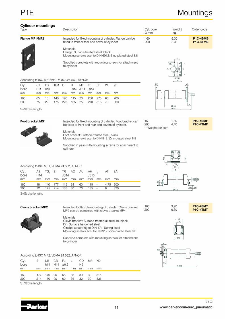
Flange MF1/MF2 Intended for fixed mounting of cylinder. Flange can be fitted to front or rear end cover of cylinder. Materials Flange: Surface-treated steel, black Mounting screws acc. to DIN 6912: Zinc-plated steel 8.8 Supplied complete with mounting screws for attachment to cylinder.
According to ISO MF1/MF2, VDMA 24 562, AFNOR
Cyl. d1 FB TG1 E R MF TF UF W ZFbore H11 H13 JS14 JS14 JS14mm mm mm mm mm mm mm mm mm mm mm
Foot bracket MS1 Intended for fixed mounting of cylinder. Foot bracket can be fitted to front and rear end covers of cylinder. Materials Foot bracket: Surface-treated steel, black Mounting screws acc. to DIN 912: Zinc-plated steel 8.8 Supplied in pairs with mounting screws for attachment to cylinder .
According to ISO MS1, VDMA 24 562, AFNOR
Cyl. AB TG1 E TR AO AU AH l7 AT SAbore H14 JS14 JS15mm mm mm mm mm mm mm mm mm mm mm
Clevis bracket MP2 Intended for flexible mounting of cylinder. Clevis bracket MP2 can be combined with clevis bracket MP4. Materials Clevis bracket: Surface-treated aluminium, black Pin: Surface hardened steel Circlips according to DIN 471: Spring steel Mounting screws acc. to DIN 912: Zinc-plated steel 8.8 Supplied complete with mounting screws for attachment to cylinder .
According to ISO MP2, VDMA 24 562, AFNOR
Cyl. E UB CB FL L CD MR XDbore h14 H14 ±0,2 H9mm mm mm mm mm mm mm mm mm
160 1,60 P1C-4SMF200 4,40 P1C-4TMF** Weight per item
160 3,90 P1C-4SMT200 6,80 P1C-4TMT
Cylinder mountingsType Description Cyl. bore Weight Order code Ø mm kg
12
P1E Mountings
08.03
www.parker.com/euro_pneumatic
Clevis bracket MP4 Intended for flexible mounting of cylinder. Clevis bracket MP4 can be combined with clevis bracket MP2. Materials Clevis bracket: Surface-treated aluminium, black Mounting screws acc. to DIN 912: Zinc-plated steel 8.8 Supplied complete with mounting screws for attachment to cylinder .
According to ISO MP4, VDMA 24 562, AFNOR
Cyl. E EW FL L CD MR XD bore ±0,2 H9 mm mm mm mm mm mm mm mm
Pivot bracket for MT4 Intended for use together with central trunnion MT4. Material Pivot bracket: Surface-treated aluminium Bearing acc. to DIN 1850 C: Sintered oil-bronze bushing Supplied in pairs.
According to ISO, VDMA 24 562, AFNOR
Cyl. B1 B2 A C d1 d2 H1 H2 fx45°lbore H13 min mm mm mm mm mm mm mm mm mm mm
Centre trunnion MT4 Intended for articulated mounting of cylinder. The trunnion is factory-fitted in the centre of the cylinder or at an optio-nal location specified by the XV-measure – see the order code key on page 7. Combined with pivot bracket for MT4. Material: Trunnion: zinc plated steel Trunnion centred The central trunnion is ordered with letter D in position.See the order code key at pages 7. Trunnion with optional locationPlease contact customer service for other XV dimensions
According to ISO MT4, VDMA 24 562, AFNOR
Cyl. TM TL TD R UW L1 X1* XV*min X2*bore h14 h14 e9mm mm mm mm mm mm mm mm mm mm
Cylinder mountingsType Description Cyl. bore Weight Order code Ø mm kg
13
P1E Mountings
08.03
www.parker.com/euro_pneumatic
Swivel rod eye Swivel rod eye for articulated mounting of cylinder. Swivel rod eye can be combined with clevis bracket GA. Maintenance-free. Materials Swivel rod eye: Zinc-plated steel SwivelbearingaccordingtoDIN648K:Hardenedsteel
According to ISO 8139
Cyl. A B B CE CN EN ER KK LE N O Z bore min max H9 h12 min mm mm mm mm mm mm mm mm mm mm mm mm
Nut Intended for fixed mounting of accessories to the piston rod.Material: Zinc-plated steel The cylinders are delivred with a zinc-plated steel piston rod nut
According to DIN 439 B
Cyl. d M S bore mm mm mm
160 M36x2 18 55200 M36x2 18 55
160 2,00 P1C-4SRS200 2,00 P1C-4SRS
160 4,30 P1C-4SRC200 4,30 P1C-4SRC
160 0,110 9128985606200 0,110 9128985606
S M
d
ØCK
B
ER
CELEA
CL
CM O
KK
M
ØCN
B
N
Z
ACE
LE
O
KK
EN
ER
ZM
Cylinder mountingsType Description Cyl. bore Weight Order code Ø mm kg
14
P1E Sensors
08.03
www.parker.com/euro_pneumatic
New drop-in sensors The completely new ”drop-in” sensors can easily be installed from the side in the sensor groove, at any position along the piston stroke. The sensors are completely recessed and thus mechanically protected. Choose between electronic or reed sensors and several cable lengths and 8 mm and M12 con-nectors. There is a double jointed adapter for the tie-rod ver-sion, which offers simple and flexible use of standard sensors.
Electronic sensors The new electronic sensors are ”Solid State”, i.e. they have no moving parts at all. They are provided with short-circuit protec-tion and transient protection as standard. The built-in electro-nics make the sensors suitable for applications with high on and off switching frequency, and where very long service life is required.
Technical dataDesign GMR (Giant Magnetic Resistance) magneto-resistive functionInstallation From side, down into the sensor groove, so-called drop-inOutputs PNP, normally open (also available in NPN design, normally closed, on request)Voltage range 10-30 VDC 10-18 V DC, ATEX sensorRipple max 10%Voltage drop max 2,5 VLoadcurrent max 100 mAInternal consumption max 10 mAActuating distance min 9 mmHysteresis max 1,5 mmRepeatability accuracy max 0,2 mmOn/off switching frequency max5kHzOn switching time max 2 msOff switching time max 2 msEncapsulation IP 67 (EN 60529)Temperature range –25 °C to +75 °C –20 °C to +45 °C, ATEX sensorIndication LED,yellowMaterial housing PA 12Material screw Stainless steelCable PVC or PUR 3x0.25 mm2
see order code respectively
Reed sensors The sensors are based on proven reed switches, which offer reliable function in many applications. Simple installation, a protectedpositiononthecylinderandclearLEDindicationareimportant advantages of this range of sensors.
Technical dataDesign Reed elementMounting From side, down into the sensor groove, so-called drop-inOutput Normally open , or normally closedVoltage range 10-30 V AC/DC or 10-120 V AC/DC 24-230 V AC/DCLoadcurrent max 500 mA for 10-30 V or max 100 mA for 10-120 V max 30 mA for 24-230 VBreaking power (resistive) max 6 W/VAActuating distance min 9 mmHysteresis max 1,5 mmRepeatability accuracy 0,2 mmOn/off switching frequency max400HzOn switching time max 1,5 msOff switching time max 0,5 msEncapsulation IP 67 (EN 60529)Temperature range –25 °C to +75 °CIndication LED,yellowMaterial housing PA12Material screw Stainless steelCable PVC or PUR 3x0.14 mm2
see order code respectively
15
P1E Sensors
08.03
www.parker.com/euro_pneumatic
Sensors Adapter
3515,7 A
B
Cyl. bore A B mm mm mm160 95 90200 112 107
31,5
37
M8x
1M
8x1
4,3
6,1
4,6
9,7
31,5 - 36
1
4
3DC
Brown
Black
Blue
1
4
3AC/DC
1
4
3+(–) V AC/DC
Signal
–(+) V AC/DC
Brown
Black
Blue
AC/DC
Brown
Blue
P8S-GRFLX / P8S-GRFLX2
143
+(–) V AC/DC
Signal–(+) V AC/DC
M8 M12
1
4
3+V DC
Signal
– V DC143
+ V DC
Signal– V DC
M8 M12
Electronic sensors Reed sensors
AC/DC
P8S-GCFPX
Brown
Blue
Dimensions
16
P1E Sensors
08.03
www.parker.com/euro_pneumatic
Ordering data
Output/function Cable/connector Weight Order code kg
Electronic sensors , 10-30 V DC
PNP type, normally open 0,27 m PUR-cable and 8 mm snap-in male connector 0,007 P8S-GPSHXPNP type, normally open 1,0 m PUR-cable and 8 mm snap-in male connector 0,013 P8S-GPSCXPNP type, normally open 1,0 m PUR-cable and M8 screw male connector 0,013 P8S-GPCCXPNP type, normally open 0,27 m PUR-cable and M12 screw male connector 0,015 P8S-GPMHXPNP type, normally open 3 m PVC-cable without connector 0,030 P8S-GPFLXPNP type, normally open 10 m PVC-cable without connector 0,110 P8S-GPFTX
Electronic sensor 18-30 V DC ATEX-certified See ATEX information in P1D catalogue
Type PNP , normally open 3 m PVC-cable without connector 0,030 P8S-GPFLX/EX
Reed sensors , 10-30 V AC/DC
Normally open 0,27 m PUR-cable and 8 mm snap-in male connector 0,007 P8S-GSSHXNormally open 1,0 m PUR-cable and 8 mm snap-in male connector 0,013 P8S-GSSCXNormally open 1,0 m PUR-cable and M8 male connector 0,013 P8S-GSCCXNormally open 0,27 m PUR-cable and M12 screw male connector 0,015 P8S-GSMHXNormally open 1,0 m PUR-cable and M12 screw male connector 0,023 P8S-GSMCXNormally open 3 m PVC-cable without connector 0,030 P8S-GSFLXNormally open 10 m PVC-cable without connector 0,110 P8S-GSFTXNormally closed 5m PVC-cable without connector 1) 0,050 P8S-GCFPX
Reed sensors, 10-120 V AC/DC
Normally open 3 m PVC-cable without connector 0,030 P8S-GRFLX
Reed sensorer, 24-230 V AC/DC
Normally open 3 m PVC-cable without connector 0,030 P8S-GRFLX2
1)WithoutLED
Adapter for tie-rod design
Description Weight Order code kg
Double jointed adapter 0,07 P8S-TMA0X
II3G EEx nA II T4X II3D 135 °C IP67
17
P1E Sensors
08.03
www.parker.com/euro_pneumatic
Type of cable Cable/connector Weight Order code kg
Cables for sensors, complete with one female connector
Cable, Flex PVC 3 m, 8 mm Snap-in connector 0,07 9126344341Cable, Flex PVC 10 m, 8 mm Snap-in connector 0,21 9126344342Cable, Super Flex PVC 3 m, 8 mm Snap-in connector 0,07 9126344343Cable, Super Flex PVC 10 m, 8 mm Snap-in connector 0,21 9126344344Cable, Polyurethane 3 m, 8 mm Snap-in connector 0,01 9126344345Cable, Polyurethane 10 m, 8 mm Snap-in connector 0,20 9126344346Cable, Polyurethane 5 m, M12 screw connector 0,07 9126344348Cable, Polyurethane 10 m, M12 screw connector 0,20 9126344349
Male connectors for connecting cablesCable connectors for producing your own connecting cables. The connectors can be quickly attached to the cable without special tools. Only the outer sheath of the cable is removed. The connectors are available for M8 and M12 screw connectors and meet protection class IP 65.
Connecting cables with one connectorThe cables have an integral snap-in female connector.
18
P1E Sensors
08.03
www.parker.com/euro_pneumatic
Connection block Valvetronic 110The Valvetronic 110 is a connection block that can be used for collecting signals from sensors at various points on a machine and connecting them to the control system via a multicore cable. Valvetronic 110 can also be used for central connection of the multi-core cable to the outputs of a control system, and can be laid to a machine where the output signals can be connected. The connection block has ten 8 mm snap-in circular connectors and a multi-core cable which is available in lengths of 3 or 10 m. The connections on the block are numbered from 1 to 10. Blan-king plugs are available for unused connections, as labels for marking the connections of each block.
Electrical data:Voltage 24 VDC (max. 60 V AC/75 V DC)Insulation group according to DIN 0110 class CLoad max.1Aperconnection total max. 3 A
Cable:Length 3 m or 10 mTypeofcable LifYY11YConductor 12Area 0.34 mm2
Colour marking According to DIN 47 100
32
1
32
1
Mechanical dataEnclosure IP 67, DIN 40050 with fitted contacts and/or blanking plugs.Temperature –20 °C to +70 °C
MaterialBody PA6,6VDaccordingtoUL94Contact holder PBTPSnap-inring LDPEMoulding mass EpoxySeal NBRScrews Plated steel
Industrial durabilityGood chemical and oil resistance. Tests should be performed in aggressive environments.
Ordering data
Designation Weight Order code kg
Connection block Valvetronic 110 with 3 m cable 0,32 9121719001 Connection block Valvetronic 110 with 10 m cable 0,95 9121719002
Blanking plugs (pack of 10) 0,02 9121719003 Use blanking plugs to close unused connections.
Labels(packof10) 0,02 9121719004 White labels to insert in grooves on the side of the connection
Dimensions and wiring diagrams
Conductor Colour Input Output
1 Pink Signal 1 Signal 1 2 Grey Signal 2 Signal 2 3 Yellow Signal 3 Signal 3 4 Green Signal 4 Signal 4 5 White Signal 5 Signal 5 6 Red Signal 6 Signal 6 7 Black Signal 7 Signal 7 8 Violet Signal 8 Signal 8 9 Grey-Pink Signal 9 Signal 9 10 Red-Blue Signal 10 Signal 10 A Blue 0 V 0 V B Brown +24 V PE
19
P1E Cylinders
08.03
www.parker.com/euro_pneumatic
Repair kits= Included in repair kit
Apply threadlocking adhesive to the grade stated= below where symbol indicates (241 multi purpose locking and sealing).