International Journal of Greenhouse Gas Control 16 (2013) 271–277
Contents lists available at SciVerse ScienceDirect
International Journal of Greenhouse Gas Control
j ourna l h o mepage: www.elsev ier .com/ locate / i jggc
ost-combustion capture of CO2 at an integrated steel mill – Part I:echnical concept analysis
ntti Arastoa,∗, Eemeli Tsuparia, Janne Kärkia, Erkki Pisiläb, Lotta Sorsamäkia
VTT Technical Research Centre of Finland, P.O. Box 1000, FI-02044 VTT, FinlandRuukki Metals Oy, Rautaruukintie 155, 92100 Raahe, Finland
r t i c l e i n f o
rticle history:eceived 19 January 2012eceived in revised form 21 August 2012ccepted 22 August 2012vailable online 9 October 2012
eywords:CS
ron and steel industryost-combustion capturelast furnacespen Plus
a b s t r a c t
In this study different possibilities for applying post-combustion capture at an integrated steel mill inorder to reduce carbon dioxide emissions were studied. Implications of different amounts of CO2 captured,different solvents for post-combustion capture and different heat supply options for solvent regenerationto the energy balance and greenhouse gas emissions of the steel mill are compared to that of the basecase for the steel mill.
The case study is based on Ruukki Metals Ltd.’s Raahe steel mill that is situated on the coast of the Gulfof Bothnia. It is the largest integrated steel mill in the Nordic countries producing hot rolled steel platesand coils. It is also the largest CO2 point source in Finland emitting approximately 4 Mt/year.
Carbon capture processes were modelled using Aspen Plus process modelling software and results wereused to estimate the potential for reducing CO2 emissions at an integrated steel mill from a plant oper-ator’s point of view. Different heat integration options and heat utilization scenarios were investigated.The heat available for solvent regeneration varied between these heat utilization scenarios and thus par-
tial capture of CO2 was investigated with the CO2 amount captured depending on the heat available forsolvent regeneration in the different case studies.
The results of the study show a significant CO2 reduction potential using CCS. Approximately 50–75% ofthe emissions from the site could be captured using post-combustion capture. Capturing a larger amountof emissions would be technically less feasible due to the large number of small stacks around the large,
integrated steel mill site.
. Introduction
It has been generally acknowledged that climate change is onef the most serious environmental threats that humankind is fac-ng and that greenhouse gas emissions (GHG’s) should be reducedn every field of activities. The iron and steel industry is responsi-le for about 10% of worldwide CO2 emissions from fossil fuel useIEA, 2008), which corresponds to about 5% of the overall globalHG emissions. CO2 emissions from iron and steel industry origi-ate mainly from the two most common steel making processes:he Blast Furnace and Basic Oxygen Furnace-based route (BF + BOFoute) and the Electric Arc Furnace route (EAF route). Togetherhese processes are responsible for about 99% of the global crude
teel production (Worldsteel, 2010). The EAF route results in sig-ificantly smaller CO2 emissions per ton of steel produced than theF + BOF route, but the EAF route is often based on recycled steel and
has a smaller unit size. In the previous decade, the growth in globalsteel production resulted mostly from the growth in production bythe BF + BOF route (Worldsteel, 2010). In addition, direct reductioniron production processes (DRI) are already used commercially, buttheir portion of the global iron production is still minimal.
Because the BF + BOF route utilizes the iron oxide found in ironore, a powerful reducing agent is needed in the blast furnace. Atypical reducing agent is coke, which eventually results in relativelyhigh CO2 emissions (due to subsequent combustion of blast furnacegas). In addition, the production of coke results in coke oven gas andeventually in CO2 emissions. Numerous improvements in the com-plicated BF + BOF-based steel mills are possible, but the reductionsin CO2 emissions are typically small in comparison to the overallCO2 emissions from the mills. By Carbon Capture and Storage (CCS),CO2 emissions could be reduced to a large extent. CCS is gener-ally recognized as one of the key climate change mitigation optionand the technology can be utilized in the steel industry as well.Due to large unit sizes, relatively high CO2 concentrations, current
utilization of pure oxygen and recoverable heat, CCS may becomeeconomically feasible in steel mills considering the likely futurecosts for CO2, for example in the EU Emission Trading Scheme (EUETS). In principle, each of the three main CCS technologies, namely
ost-combustion, pre-combustion and oxyfuel can be utilized inteel mills. Economically feasible options for reducing CO2 emis-ions are of high interest to European steel producers because ofhe additional costs due to the EU ETS. While the market for powers typically national or regional, the market for steel is global. Thedditional production costs due to emission trading can thereforeot be transferred to the product price in order for steel to stayompetitive in the global market. Therefore, the additional costsue to CCS are even more challenging for the steel industry.
Ruukki Metal Oy’s Raahe steel mill is situated on the cost of theulf of Bothnia. It is the largest integrated steel mill in the Nordicountries producing hot rolled steel plates and coils. It is also theargest CO2 point source in Finland. In 2008, before the economicown term and blast furnace revisions, the CO2 emissions fromhe mill were 4.5 Mt/year (EMV, 2011). Replacing sinters by pelletsrom 2011 onwards reduced the direct CO2 emissions from the sitey 0.4 Mt/a.
In this study, different possibilities for reducing carbon dioxidemissions at an integrated steel mill by applying post-combustionapture (PCC) for were studied, using the Raahe steel mill as a basease. Technical implications of different post-combustion captureethods and different amounts of CO2 captured as well as energy
alances are presented in this paper. Based on the technical solu-ions described in this paper, the economics of the solutions andheir net effect on the greenhouse gas emissions are assessed inhe second part of the study (Tsupari et al., 2012).
. Methods
.1. General
The CO2 capture processes and the steelmaking processes wereodelled using Aspen Plus modelling software and the results were
sed to estimate the CO2 emission reduction potential using PCCechnologies at an integrated steel mill. Only the parts of the steel-
aking processes affected by the CO2 capture were modelled withspen Plus. Different CO2 capture amounts were investigated with
he amount captured depending on solvent properties and heatvailable for solvent regeneration using two different heat produc-ion solutions.
.2. Boundaries of evaluation
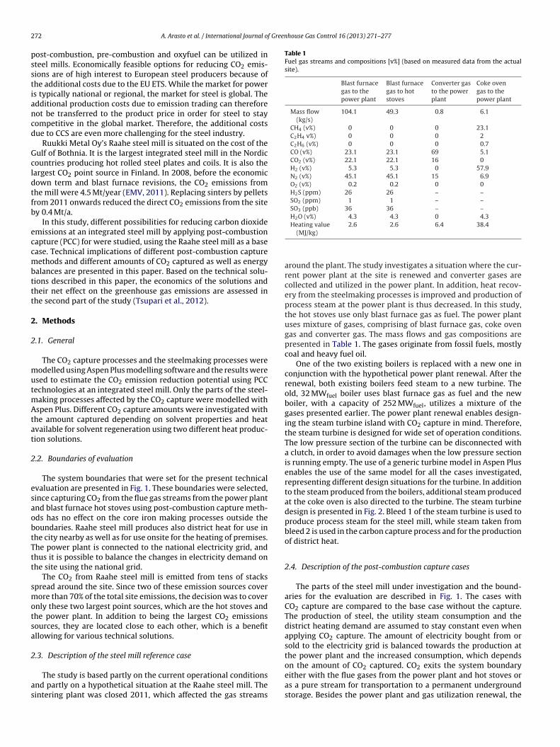
The system boundaries that were set for the present technicalvaluation are presented in Fig. 1. These boundaries were selected,ince capturing CO2 from the flue gas streams from the power plantnd blast furnace hot stoves using post-combustion capture meth-ds has no effect on the core iron making processes outside theoundaries. Raahe steel mill produces also district heat for use inhe city nearby as well as for use onsite for the heating of premises.he power plant is connected to the national electricity grid, andhus it is possible to balance the changes in electricity demand onhe site using the national grid.
The CO2 from Raahe steel mill is emitted from tens of stackspread around the site. Since two of these emission sources coverore than 70% of the total site emissions, the decision was to cover
nly these two largest point sources, which are the hot stoves andhe power plant. In addition to being the largest CO2 emissionsources, they are located close to each other, which is a benefitllowing for various technical solutions.
.3. Description of the steel mill reference case
The study is based partly on the current operational conditionsnd partly on a hypothetical situation at the Raahe steel mill. Theintering plant was closed 2011, which affected the gas streams
Heating value(MJ/kg)
2.6 2.6 6.4 38.4
around the plant. The study investigates a situation where the cur-rent power plant at the site is renewed and converter gases arecollected and utilized in the power plant. In addition, heat recov-ery from the steelmaking processes is improved and production ofprocess steam at the power plant is thus decreased. In this study,the hot stoves use only blast furnace gas as fuel. The power plantuses mixture of gases, comprising of blast furnace gas, coke ovengas and converter gas. The mass flows and gas compositions arepresented in Table 1. The gases originate from fossil fuels, mostlycoal and heavy fuel oil.
One of the two existing boilers is replaced with a new one inconjunction with the hypothetical power plant renewal. After therenewal, both existing boilers feed steam to a new turbine. Theold, 32 MWfuel boiler uses blast furnace gas as fuel and the newboiler, with a capacity of 252 MWfuel, utilizes a mixture of thegases presented earlier. The power plant renewal enables design-ing the steam turbine island with CO2 capture in mind. Therefore,the steam turbine is designed for wide set of operation conditions.The low pressure section of the turbine can be disconnected witha clutch, in order to avoid damages when the low pressure sectionis running empty. The use of a generic turbine model in Aspen Plusenables the use of the same model for all the cases investigated,representing different design situations for the turbine. In additionto the steam produced from the boilers, additional steam producedat the coke oven is also directed to the turbine. The steam turbinedesign is presented in Fig. 2. Bleed 1 of the steam turbine is used toproduce process steam for the steel mill, while steam taken frombleed 2 is used in the carbon capture process and for the productionof district heat.
2.4. Description of the post-combustion capture cases
The parts of the steel mill under investigation and the bound-aries for the evaluation are described in Fig. 1. The cases withCO2 capture are compared to the base case without the capture.The production of steel, the utility steam consumption and thedistrict heating demand are assumed to stay constant even whenapplying CO2 capture. The amount of electricity bought from orsold to the electricity grid is balanced towards the production atthe power plant and the increased consumption, which dependson the amount of CO2 captured. CO2 exits the system boundary
either with the flue gases from the power plant and hot stoves oras a pure stream for transportation to a permanent undergroundstorage. Besides the power plant and gas utilization renewal, the
A. Arasto et al. / International Journal of Greenhouse Gas Control 16 (2013) 271–277 273
ill for
is
uait(fcgpccofltt
Fig. 1. System boundaries at Raahe steel m
nstallation of the carbon capture island takes place in an existingite infrastructure.
Blast furnace gas represents by far the largest fuel gas streamtilized within the boundaries of this study (Table 1). Since themounts of other fuel gases used are small, there are no signif-cant differences between the flue gases of the power plant andhe hot stoves regarding composition, CO2 content and impuritiesTable 3). Because of this, no significant advantage would be gainedrom treating these gas streams in separate capture units. A singleapture island could be used thanks to the close location of the flueas stream sources and the steady operation of the both sourcerocess units. In addition to this, only a single location suitable foronstructing a capture island on could be found within a reasonablylose proximity of the sources. This also justifies the combination
f the two flue gas streams into a single capture island. When theseue gases are combined, the total maximum CO2 flow to the cap-ure unit is 103 kg/s. In all CO2 capture cases, a 90% capture rate ofhe CO2 in the flue gases treated was targeted for.
the energy balance and CO2 capture study.
Heat integration opportunities for CO2 capture process arebased on matching the heat levels, heat sources and sinks. Heatcan be recovered from steelmaking processes or generated in theboilers at the steel mill site. The heat can be utilized in electricityproduction and for solvent regeneration. Other utility consump-tions of heat, the demand of district heat and the utilization ofprocess steam on-site are considered to be equal in all modelledcases. As heat integrations play a significant role in the study, theavailable heat streams were divided into four categories for facili-tating heat integration according to temperature and level of exergy(Table 2). The process steam that can be utilized in steelmaking pro-cesses is ranked as highest quality heat and set to category 1, whilethe lowest quality heat (that is still good for preheating the returnstream from district heating) is set to category 4. The heat streams
were integrated for maximizing CO2 recovery, within the boundaryconditions. The integration was adjusted so that the demands forprocess steam and district heat were always satisfied. In additionto the utilization of heat as process steam, in solvent regeneration
274 A. Arasto et al. / International Journal of Greenhouse Gas Control 16 (2013) 271–277
Fig. 2. Design parameters and turbine design for Raahe steel mill.
Table 2Categorization of heat streams available based on temperature.
Category Temperature level Description Sources
1 Over 180 ◦C Superheated 8 bar process steam 8 bar bleed from turbine◦ t heat
re solvting
abt
gagtm
ctut
TT
2 Over 130 C MEA regeneration, distric3 Over 80 ◦C Advanced low temperatu4 Over 60 ◦C Preheating for district hea
nd for district heating, the heat was also utilized for preheating ofoiler feed water for improving the steam and electricity produc-ion efficiency.
The starting point for capturing carbon dioxide from the flueases was a conventional MEA based solvent scrubbing process. Inddition to this, the usage of two alternative solvents was investi-ated with a rough, conceptual study. This was performed to studyhe possible effects and benefits for CO2 capture in the future when
ore advanced methods have been developed.Sulphur removal from the flue gases prior to the post-
ombustion CO2 capture unit is generally required. At the steel mill,
he blast furnace gas is already purified with a wet scrubber prior totilization in the hot stoves and the power plant boiler. This leadso a rather low SOx concentration in the flue gases of the power
ing 3 bar bleed, mill heat recovery (steam, hot water)ent regeneration 3 bar bleed, mill heat recovery (steam, hot water)
Mill and CCS heat recovery (steam, hot water)
plant and the hot stoves. The investment required for an additionalSO2 scrubber was considered to be a trade-off to avoid an increasedMEA makeup and corrosion in the CO2 scrubber. However, the SO2content in the flue gases was according to the simulations 17 ppm-v, which is in line with the level that can be found in the literaturefor an acceptable concentration suitable for a CO2 scrubber (NETL,2007, 2009; EPRI, 2007). Therefore, no additional sulphur removalunits were needed. The sulphur content could also be further low-ered slightly by improving the existing SO2 removal. The simulatedNOx concentration in the flue gas was very low, approximately12 ppm.
2.4.1. MEA capture processThe amine capture process was modelled using a standard 30%
MEA solvent. The capture process consists of an absorber unitand a stripper unit, pumps and heat exchangers. The process wasmodelled with an equilibrium model found in the Aspen Plus pro-cess simulation software (Fig. 3). Rate-based simulation models areknown to be superior to equilibrium-state models for MEA mod-elling (Zhang et al., 2009; Taylor et al., 2003). However, a simplerequilibrium model was considered to be sufficiently accurate forthe accuracy needed in this level of concept analysis, where thecapture process is only one component of many.
The absorber was modelled using a Sulzer Mellapak structuredpacking. The flue gas is cooled down with a wet scrubber before theabsorber unit. In the absorber, the CO2 of the flue gas is absorbed by
the MEA solvent to form stable chemical compounds. The absorberis operated near atmospheric pressure. According to Abu-Zahraet al. (2007) the optimum feed temperature for the solvent is 40 ◦C.The absorber was modelled as a packed colon with 10 ideal trays
A. Arasto et al. / International Journal of Greenhouse Gas Control 16 (2013) 271–277 275
mode
a0svCptswis
waimt2
ifPen
2
afticNapoii(
Fig. 3. Aspen Plus process
nd an L/G ratio of 4.2 l/m3, with the solvent lean loading being.22 mol/mol. The rich solvent from the absorber is led into thetripper unit via a cross heat exchanger. The loading of the rich sol-ent was 0.49 mol/mol. In the stripper unit the chemically boundO2 is released from the solvent by heating it to 122 ◦C with lowressure steam at 133–160 ◦C (3.0–6.2 bar). The CO2 exiting fromhe top of the stripper is led to a condenser to remove the water andolvent from the gas and return it for use in the process. Part of theater is removed from the process at this stage. The lean solvent
s then led back to the absorber unit via cross heat exchanger. Thetripper is operated at approximately 2 bar pressure.
A small amount of solvent and water is lost from the processith the exiting flue gas flow from the absorber unit. In addition,
small amount of solvent is removed from the system to removempurities and degraded solvent. Because of this, water and solvent
akeup is added to the process. The amount of solvent consump-ion was set to be 1.5 kg/tcaptured (similarly to Abu-Zahra et al.,007).
According to the simulations, the regeneration energy neededn the process is approximately 3.4 MJ/kg captured CO2. This is byar the largest energy consumer in the flue gas scrubbing process.ower is also needed in the capture process for pumps and blow-rs for flue gas and solvent recirculation in addition to the powereeded for CO2 compression.
.4.2. Alternative solvent optionsThe standard MEA solvent can to some extent be considered
s outdated and not the best performing state-of-the-art solventor new CO2 removal processes. Because of this, two other cap-ure processes were conceptually evaluated to reflect likely futuremprovements in solvent scrubbing technologies and their impli-ations to carbon capture processes with steel mill integration.evertheless, MEA solvent-based processes are the most evaluatednd best known processes, providing a baseline reference to com-are results with other studies. However, these alternative solvent
ptions reflect better the solvent options available for a steel milln the future. As the CO2 concentration in the flue gas in this cases higher than in the alternative solvent studies used as referenceFortum, 2009; Zhang et al., 2010), the results from the regeneration
l of MEA capture process.
energy requirement calculations may be conservative in compari-son to the real potential of alternative solvents in CO2 capture plantsin steel mills. These evaluations are based partly on current opera-tional conditions and partly on hypothetic assumptions, and madeto reflect the impact of possible future improvements in solventscrubbing technologies in the future.
The evaluation of the first of the two alternative solvents is basedon public information available on the Siemens amino acid salt CO2capture technology (referred to as “advanced” later on in the text).This technology was chosen in the Fortum FINNCAP project target-ing to the demonstration of CO2 capture at Meri-Pori condensingpower plant (Fortum, 2009). The most significant benefit with thissolvent in comparison to MEA solvents is the low regenerationenergy requirements of 2.7 MJ/kg CO2 (Fortum, 2010). In addition,the operational costs associated are expected to be slightly lowercompared to baseline MEA. This was mainly due to a lower sol-vent make up consumption which was, based on the environmentalimpact assessment of FINNCAP project (Fortum, 2010), estimatedto be only 13% of the consumption estimated for MEA.
The second evaluation with an alternative solvent is based onan imaginary solvent (referred to as “low-T” later on in the text),able to be regenerated at a significantly lower temperature thanbaseline MEA. This is assumed to be the result of solvent develop-ment work in the future. Having a lower regeneration temperature,even at the expense of relatively high regeneration energy, couldopen up new opportunities for CO2 capture implementation, espe-cially in the process industry, where low-temperature waste heatstreams are readily available. The regeneration is set to occur at70 ◦C, which enables a significantly larger share of the waste heatstreams to be utilized for solvent regeneration and thus increase theamount of CO2 that can be captured. In theory, it could be possible todevelop these kinds of solvents (Zhang et al., 2010) if the advantagesachieved with low temperature regeneration would compensatefor other disadvantages. Regeneration energy of 3.0 MJ/kg CO2 wasassumed based on Zhang et al. (2010).
2.4.3. CO2 processingSince there is no capacity for geological storage of CO2 in
Finland the CO2 has to be transported and stored outside Finland’s
276 A. Arasto et al. / International Journal of Greenhouse Gas Control 16 (2013) 271–277
ression train for ship transportation.
bmssantiisstoitsspt
2
afitc
nbr
bfcftssl
srtag
sbola
Table 4The calculated energy balance for different scenarios with each solvent studied.
Heat used for solvent regeneration [GWh/a]MEA 0 1795 2581Advanced 0 1795 2198
Fig. 4. A seven staged CO2 comp
orders (Teir et al., 2011). Ship transportation from Finland is theost economical solution for transporting of CO2 from a single CO2
ource to a storage site outside Finland (Kujanpää et al., 2011). Forhip transportation CO2 has to be pressurized and cooled down topproximately 6.5 bar and −52 ◦C. To reach these conditions withormal cooling water temperatures CO2 has first to be compressedo approximately 60 bar. CO2 is cooled down to −52 ◦C by flash-ng the pressurized CO2 to 6.5 bar. When CO2 is flashed, part of its evaporated. The evaporated part is returned to the compressiontage for the corresponding pressure level. Compression is done ineven stages, to enable an efficient heat recovery (Fig. 4). An isen-ropic efficiency of 0.8 was used in the compressors models. Mostf the energy in CO2 compression is used for liquefying CO2. CO2s cooled down to 15 ◦C between the compression stages. Some ofhis low temperature level heat can be utilized to preheat the returntream from district heating network. The power requirement forhip transportation is not much smaller than that for pipeline trans-ortation despite the pressure difference. This is because of theemperature requirements and thus recompression needed.
.5. Scenarios
Using the parameters, assumptions and modelling describedbove, the energy balance and CO2 emissions could be calculatedor the steel mill. As described above, the approach allowed thenvestigation of energy and carbon dioxide emission balances withhree different heat production scenarios resulting in different CO2apture scenarios:
Scenario 1: no carbon capture. This is the baseline scenario, witho carbon capture process in place. The plant operates according tousiness as usual, and the power and heat are produced at a normalate.
Scenario 2: turbine back pressure operation. The size of the car-on capture installation is designed for utilizing the steam availablerom the steam turbine in back pressure operation. This enablesapture of CO2 and heat production for covering the heat demandor both the still mill and the district heating network. In addi-ion, some electricity generation is possible with the high pressureteam. The sizing of the capture plant is based on the amount ofteam going to the low pressure section of the turbine in the base-ine scenario.
Scenario 3: no electricity production. The carbon capture plant isized for a case where all available thermal power is utilized foregeneration of the solvent. Only the steam and heat demands ofhe steel mill are satisfied and all other heat is utilised for regener-tion of the solvent. In this scenario there is no on-site electricityeneration.
The implications of the CO2 capture on the energy balance of theteel mill site are presented in Table 4. District heat sold from the
oundary was constant in every case, 300 GWh/a, which is basedn the district heat demand in the surrounding city of the mill. Theargest captured CO2 amounts (2.9 Mt/a) were in the cases wherell available fuel power was used for regenerating the solvent. With
Low-T 0 2041 2442
only the low pressure steam available for solvent regeneration thecaptured amounts were in the range of 1.9–2.4 Mt/a. The amountsof CO2 captured are presented in Fig. 5. In addition to the steamconsumption in regeneration of solvent, also power is consumedin the process. The total power consumption of CCS processes wasestimated to be 0.41 MJ/kg CO2 captured. This comprises of pumps,compressors and other auxiliaries. Most of the electricity is con-sumed in the CO2 compression.
As the amount of captured CO2 gets higher, the capacity for elec-tricity production on the power plant gets smaller, as the steam isutilized for regeneration of the solvent instead of utilized in thelow pressure section of the steam turbine. In the reference casethe annual electricity production is around 1200 GWh/a. When lowpressure steam is utilized for solvent regeneration, the electricityproduction decreases by 40% to 730 GWh/a. When all fuel poweris utilized to produce steam for regeneration, no electricity is pro-duced on site.
When different solvent options are considered, the low tem-perature solvent was found to be the best CO2 capture option, eventhough it had a higher regeneration energy than the advanced sol-vent. This is due to the higher ability to utilize low exergy heat thatis widely available at site and cannot be utilized in large extent withother solvents considered. In addition, all measures for low temper-ature heat recovery were not mapped at the site, so it is possiblethat even more CO2 could be captured using the low temperaturesolvent than what was found in these calculations. In industrialapplications, such as for steel mills, where large amounts of lowquality heat are available, utilization of a solvent regenerable ata low temperature would cover for a number of other possibledrawbacks with the particular solvent, such as a higher nominalregeneration energy, higher circulation rates or faster degradation.In terms of the amount of CO2 that could be captured, the advancedsolvent proved to be almost as good as the low temperature sol-vent with only a minimal difference. When comparing MEA with
the advanced solvent roughly 8% less CO2 could be captured withthe same integrations and utilization scenarios.
A. Arasto et al. / International Journal of Greenhouse Gas Control 16 (2013) 271–277 277
-4.0
-3.0
-2.0
-1.0
0.0
1.0
2.0
3.0
ssure
CO2
[Mt/
a]
Captured, MEA
Captured,advanced
Captured, Low-T
tured
3
gcseyaaaadl
pimpecootttp
A
nafFnbAEpe
process modeling study of CO2 capture with aqueous monoethanolamine
No carbon capture Turbine back pre
Fig. 5. The effect of CCS on the amount of CO2 that can be cap
. Conclusion and discussion
As a technical option, it is possible to significantly lowerreenhouse gas emissions from the steel industry with the postombustion capture technologies covered in this study. Theolutions are technically realisable already in the near future. Nev-rtheless, no commercial application for such a large scale existset. The larger capture amounts studied (2–3 Mt CO2/a) account forpproximately 50–75% of the CO2 emissions from the site. If largermounts of emissions were to be captured it would be technicallynd economically significantly less feasible in comparison to onlypplying CCS for the largest emission sources on the site. This isue to the large number of small stacks scattered around the fairly
arge production site.There are other carbon abatement options for iron and steel
roduction. CO2 emissions can be lowered for example by utiliz-ng bio char as a reducing agent, applying different energy saving
easures, etc. The high level of integration typical in modern steellants makes further energy saving measures of any significantxtent difficult. Large-scale bio char utilization is restricted byonstrained resources and sustainability questions. Generally, alsother CO2 emission reduction options, such as electric arc furnacesr DRI processes, exists, but these are only applicable for certainypes of steel mills. While being important and cost effective at best,hese measures are generally of smaller scale, when compared tohe order of millions of tons of CO2 emission reductions that areossible with CCS.
cknowledgements
This paper is published as a part of research in Finnishational technology programmes Climbus and CCSP on carbonbatement options for steel mills covering also oxygen blasturnace. The research was carried out in a project called CCSinland (2008–2011). The project was coordinated by VTT Tech-ical Research Centre of Finland with participation and financingy Geological Survey of Finland (GTK), Tekes (the Finnish Funding
gency for Technology and Innovation), Fortum, Foster Wheelernergy, Metso Power, Pohjolan Voima, Ruukki, and Vapo. All theartners are sincerely acknowledged. The authors want to acknowl-dge also Lauri Kujanpää and Reetta Sorsa from VTT Technical
opera�on No electricity produc�on
with the studied solvents at the chosen boundary conditions.
Research Centre of Finland for their valuable contribution in thework.
References
Abu-Zahra, M.R.M., Niederer, J.P.M., Feron, P.H.M., Versteeg, G.F., 2007. CO2 capturefrom power plants. Part II. A parametric study of the economical performancebased on mono-ethanolamine. International Journal of Greenhouse Gas Control1 (2), 135–142.
EMV, 2011. Emission Allowance Balance. Energy Market Authority of Finland,http://www.emvi.fi/files/paastooikeustase2010.pdf (in Finnish).
EPRI, 2007. Review of CO2-Capture Development Activities for Coal-Fired PowerGeneration Plants. EPRI, Palo Alto, CA, 1012239.
Fortum, 2009. Presentation in Application of CCS in Finland , Seminar 28th October,2009 by Mikko Iso-Tryykäri, Available at: http://www.vtt.fi/files/projects/ccsfinland/seminaari2009/6-iso-tryykari-fortum.pdf (in Finnish).
Fortum, 2010. Environmental Impact Assessment for Carbon Capture in Meri-Pori Power Plant, Available at: http://www.ely-keskus.fi/fi/ELYkeskukset/varsinaissuomenely/Ymparistonsuojelu/YVA/paattyneet/energiansiirto/Documents/forhiiliv/Forhiili YVAselostus.pdf (in Finnish).
IEA, 2008. CO2 Capture and Storage. A Key Carbon Abatement Option. InternationalEnergy Agency, France, 266p. ISBN 978-92-64-041400.
Kujanpää, L., Rauramo, J., Arasto, A., 2011. Cross-border CO2 infrastructureoptions for a CCS demonstration in Finland. Energy Procedia 4, 2425–2431,http://dx.doi.org/10.1016/j.egypro.2011.02.136.
NETL, 2007. Cost and Performance Baseline for Fossil Energy Plants, Volume 1: Bitu-minous Coal and Natural Gas to Electricity Final Report (Original Issue Date,May 2007) Revision 1, August 2007, DOE/NETL-2007/1281. National EnergyTechnology Laboratory.
NETL, 2009. Assessment of Power Plants That Meet Proposed Greenhouse Gas Emis-sion Performance Standards, November 5, 2009, DOE/NETL-401/110509. U.S.Depatement of Energy, National Energy Technology Laboratory.
Taylor, R., Krishna, R., Kooijman, H., 2003. Real-world modeling of distillation. Chem-ical Engineering Progress 99, 28–39.
Teir, S., Arasto, A., Tsupari, E., Koljonen, T., Kärki, J., Kujanpää, L., Lehtilä, A., Niem-inen, M., Aatos, S., 2011. Hiilidioksidin talteenoton ja varastoinnin (CCS:n)soveltaminen Suomen olosuhteissa. Espoo, VTT. 76 s.+liitt. 3 s. VTT Tiedot-teita – Research Notes 2576, ISBN 978-951-38-7697-5, 978-951-38-7698-2http://www.vtt.fi/inf/pdf/tiedotteet/2011/T2576.pdf
Tsupari, K., Arasto, P., 2012. Post combustion carbon capture at an integrated steelmill – part II: economic feasibility. International Journal of Greenhouse GasControl, http://dx.doi.org/10.1016/j.ijggc.2012.08.017, in press.
Zhang, J., Chen, J., Misch, R., Agar, D., 2010. Carbon dioxide absorption in biphasicamine solvents with enhanced low temperature solvent regeneration. ChemicalEngineering Transactions 21, 169–174, http://dx.doi.org/10.3303/CET1021029.