18
POST HOLE DIGGER OPERATION, SERVICE, & PARTS MANUAL FOR MODEL D60 September 2006 FORM :D60Digger

POST HOLE DIGGER
OPERATION, SERVICE, & PARTS MANUAL
FORMODEL D60
September 2006
FORM :D60Digger

TABLE OF CONTENTS
Introduction ................................................... 1
Preparation ................................................... 2
Safety Information ........................................ 3
Assembly Instructions ................................... 4
3-Point Hitch Adjustments ........................... 5
Operating Digger ........................................... 6
Lubrication & General Maintenance ............ 7
Components D60 ......................................... 8-9
Gearbox Breakdown .................................. 10-11
Eurocardan Driveline Breakdown ............... 12
ITG Driveline Breakdown ............................ 13
Down Force Kit .......................................... 14-15
Limited Warranty ......................................... 16

Thank you for purchasing a Gearmore Digger.
In order to be able to safely and properly operate this digger, it will be necessary for you to familiarize yourself with the contents of the entire manual before you attempt to assemble and operate your digger.
Please read all safety and assembly instructions before attempting to operate digger.
Date of Purchase: ________________________
Model Number: __________________________
Serial Number: __________________________
1
INTRODUCTION

WARNINGTo prevent possible personal injury or death during assembly, installation, operation, adjustment, or removal of implement, DO NOT wear loose cloth-ing, always wear gloves and safety glasses or face shield. Keep other persons a minimum of twenty-fi ve feet (25') away from any unit under power.
READ THIS BEFORE OPERATING DIGGER
TRAINING:
Know your controls. Read this operator's manual and the manual provided with your tractor. Learn how to stop the tractor, engine and digger quickly, in case of an emer-gency.
DO NOT allow children to operate machine, or adults to operate it without proper instructions.
PREPARATION:
♦ Clear area of debris.
♦ Never permit any person other than the operator to ride on board the tractor at any time.
♦ DO NOT allow riders on digger at any time.
♦ Operate only in daylight or good artifi cial light.
♦ Ensure all safety shielding is properly installed.
♦ Always wear relatively tight and belted clothing when operating digger. Loose clothing should not be worn, as it could get caught in the moving parts or controls.
2
PREPARATION

OPERATIONAL SAFETY:♦ Guards and safety shields are for your protection. DO NOT operate equipment unless they are in place.♦ Always operate tractor PTO (power take-off) at recommended RPM (revolutions per minute).
♦ Disengage tractor PTO and shift into neutral before attempting to start engine.
♦ Read and observe all safety decals on the tractor and digger.
♦ NEVER allow anyone within 25' of machine while it is in operation.
♦ Do not stop or start suddenly when going uphill or downhill. Avoid operation on steep slopes.
♦ Be alert for holes in terrain and other hidden hazards. Always drive slowly over rough ground.
♦ Reduce speed on slopes and in sharp turns to prevent tipping or loss of control. Be careful when changing direction on slopes.
♦ Stop digger and tractor immediately upon striking an obstruction. Turn off engine, inspect digger, and repair any damage before resuming operation.
♦ Disengage power to digger and stop engine before dismounting from tractor, before making any repairs or adjustments, transporting, or unclog- ging digger.
♦ Take all possible precautions when leaving tractor unattended: Disengage PTO, lower digger, shift into neutral, set parking brake, stop engine and remove key from ignition.
♦ Front tractor weights or front tire ballast should be used to enhance front end stability on small tractors.
♦ Check to make sure PTO is properly connected and that the driveline is correct to prevent bottoming out or pulling apart during the full lift range of the hitch.
♦ This implement is designed for a one-man operation. It is the responsibility of the tractor operator to see that no one is in the proximity of the imple- ment when it is started. DO NOT operate the implement with another person within 25' of the implement, PTO drive, or auger.
3
SAFETY INFORMATION

ASSEMBLY INSTRUCTIONS
4
The Gearmore Diggers are shipped disassembled in three (3) pieces.
1. The gearbox assembly. Gearbox is shipped with no oil.
2. The yoke assembly.
3. The boom assembly and driveshaft assembly with pins and operating instructions packet.
Please assemble in the following manner:
1. Attach end of boom to upper 3-point link bracket of the tractor.
2. Attach yoke lift pins into bottom lift arms of tractor. Attach with lynch pins (not supplied).
3. Bolt yoke to boom with 3/4" x 5-1/2" grade 5 bolt & nyloc nut.4. Raise gearbox assembly up and attach it to the boom with the supplied pin, fasten into place with two cotter pins.
5. Slide driveshaft onto input shaft of gearbox and secure with 3/8" x 2-1/4" shear bolt.
6. Install safety roll pin on implement yoke. This will prevent driveshaft from coming off input shaft if shear bolt shears.
7. Install input shaft shield onto gearbox.
8. Install other end of driveshaft to tractor PTO. Raise and lower digger assembly to verify driveshaft is not bottoming out or pulling apart during the full lift range of the hitch.
9. Slide auger adapter shield onto auger to be used.
10. Attach auger to output shaft using 1/2"x3 1/2" grade 2 bolt.
11. Make sure all bolts and pins are in place and secure before operating digger.

The average operating range of the digger should be between 5" and 65" above ground level. It is recommended that the 3-point hitch be adjusted toward the minimum required operating range, due to the fact that the greater the operating range, the less force there is available for raising the auger in diffi cult soil conditions.
CAUTION
Any time an adjustment is made to the 3-point hitch, reference should be made to the 3-point hitch section of the tractor operator's manual. Af-ter any adjustments, the digger should be carefully raised and lowered through its operating range and checked for interference.
To change vertical limits of the digger (transport height and digging depth).
1. Attach front end of boom to a hole in the upper link bracket. Upper holes will lower the digger; lower holes will raise the digger.2. Check tractor hydraulic system to be sure it is raising and lowering to its maximum and minimum recommended heights. Transport height and digging depth can be limited by adjusting lift control handle limit stops.3. If the front end of the boom strikes some part of the tractor when digger is raised or lowered: a. Make adjustments under Ref. 1. b. If at all possible, relocate or adjust the part of the tractor that is causing the interference.4. If the tractor has diffi culty raising the digger, decrease the lift range.5. If the tractor hitch raises or lowers rapidly during hydraulic functions, refer to hydraulic adjustment section of the tractor manual.
3-POINT HITCH ADJUSTMENTS
5

OPERATING DIGGER
6
WARNING
Never operate digger without gloves and eye protection. Keep other per-sons a minimum of twenty-fi ve feet (25') away from the digger operation.
TO OPERATE DIGGER1. With your digger correctly assembled and attached to the tractor, engage the tractor PTO at idling speed to give the digger a test run. Then disengage tractor PTO. 2. Place the auger at a vertical position at the desired location of the fi rst hole. 3. Set tractor brake to hold the tractor at the correct position and to prevent damage to the digger. 4. Make sure gloves are on, eye protection is in place, and that nobody is within twenty-fi ve feet (25') of the operation. Engage PTO with the engine at a little more than idle (this speed will depend on soil conditions and experience will help determine proper speed).5. Slowly lower digger to the ground. After the auger goes a foot or so into the ground, raise auger almost out of the hole, this allows the auger to clean itself of loose soil. Then drill deeper and raise the auger again. Repeat this procedure until the desired hole depth is reached. Do Not raise digger too high with PTO running, as it will damage the PTO shaft.6. When desired hole depth is reached, disengage PTO and raise auger from the hole. For tractors that require PTO engagement to produce lifting power, allow auger to turn at idle while raising it from the hole.7. If shear bolt breaks: a. Shut-off tractor engine and allow PTO shaft to come to a complete stop. b. Remove broken shear bolt. c. Install new shear bolt (part # 633154), then tighten the shear bolt nut securely. 8. If auger becomes lodged on an obstruction under ground, shut-off PTO and tractor engine. Turn the auger several revolutions in reverse. Never attempt to use hydraulic lift of tractor to dislodge auger.
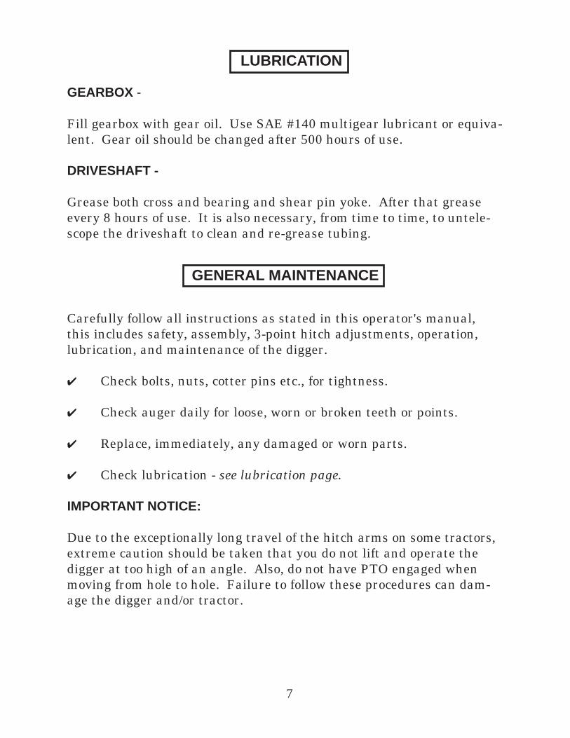
GEARBOX -
Fill gearbox with gear oil. Use SAE #140 multigear lubricant or equiva-lent. Gear oil should be changed after 500 hours of use.
DRIVESHAFT -
Grease both cross and bearing and shear pin yoke. After that grease every 8 hours of use. It is also necessary, from time to time, to untele-scope the driveshaft to clean and re-grease tubing.
Carefully follow all instructions as stated in this operator's manual, this includes safety, assembly, 3-point hitch adjustments, operation, lubrication, and maintenance of the digger.
Check bolts, nuts, cotter pins etc., for tightness.
Check auger daily for loose, worn or broken teeth or points.
Replace, immediately, any damaged or worn parts.
Check lubrication - see lubrication page.
IMPORTANT NOTICE:
Due to the exceptionally long travel of the hitch arms on some tractors, extreme caution should be taken that you do not lift and operate the digger at too high of an angle. Also, do not have PTO engaged when moving from hole to hole. Failure to follow these procedures can dam-age the digger and/or tractor.
GENERAL MAINTENANCE
7
LUBRICATION

D60 DIGGER BREAKDOWN
8

PARTS LISTING
9
REF # QTY. PART NO. DESCRIPTION
1 1 634150 Gearbox, Complete with Shields 2 1 634039 Boom 3 1 640624 Lift Bracket 4 2 634042 Cat. I & II Hitch Pin 5 1 634167 Pin w/Cotter Pin, Gearbox to Boom (7/8" x 7 3/4") 6 1 634041 Lift Bracket Bolt 3/4" x 5 1/2" w/Locknut 7 1 630030 Auger Adapter Shield Output Shaft 8 1 681035 Gearbox Shield, Input Shaft 9 1 500101 Auger Bolt 1/2" x 3 1/2" 5-Pack 10 633154 Shear Bolt PTO 3/8" x 3" (not shown)
Parts For 660, 960, 1260, & 1860 Augers
11 1 600660 Point Bolt 1/2" x 3" 12 1 600530 Point, Auger w/Bolt 13 As Req'd 630223 Tooth, Standard w/Bolts As Req'd 630222 Tooth, Hardfaced w/Bolts
Parts For "P" Series TriMax Augers - Pengo
14 1 135088 Pilot Bit Tri-Flow 15 As Req'd 35 Tooth - Standard 16 As Req'd 37 Tooth - Gage
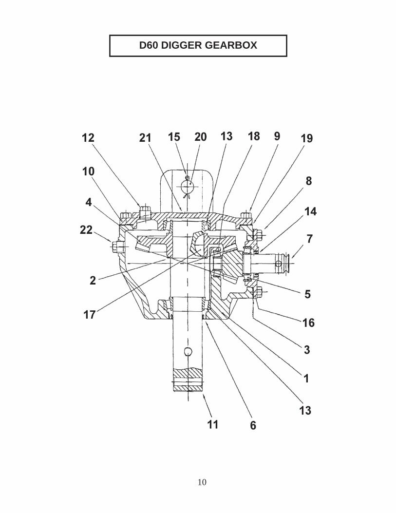
D60 DIGGER GEARBOX
10

REF # PART # QTY. DESCRIPTION 1 634150 1 Gearbox Complete, (Comer) L-196J 2 634151 1 Housing 0.196.0300.00 3 634152 1 Shim 0.195.7500.00 4 634154 1 Ring Gear Z35 0.196.6000.00 5 LM67048 1 Bearing Cone 5 LM67010 1 Bearing Cup 6 20263TLH 1 Seal Output 2" x 2 5/8" x 5/16" 8.7.1.02529 7 634156 1 Pinion Gear 11T 0.196.5000.00 8 634157 4 Bolt Front Cap M10 x 40 8.1.1.00745 9 634158 6 Bolt Top Cap M10 x 30 8.1.1.00073 10 634159 1 Top Cap 0.196.1300.00 11 634160 1 Output Shaft 0.196.3001.00 12 634161 1 Oil Plug 1/2" 8.6.5.00203 13 LM104949 2 Bearing Cone 13 LM104911 2 Bearing Cup 14 12172TB 1 Input Seal 1 1/4" x 1 3/4" x 5/16" CR12371 15 634163 2 Cotter Pin 3/16" x 1" 16 634164 1 Front Cap 0.196.1301.00 17 634165 1 Woodruff Key 7.94 x 16.28 0.196.7000.00 18 LM11910 1 Bearing Cup 18 LM11949 1 Bearing Cone 19 634166 1 Front Gasket Kit 0.196.7200.00 20 634167 1 Pin Gearbox to Boom 7/8" x 7 3/4" 22 634168 1 Solid Plug 3/8" 0.196.1302.00
D60 DIGGER GEARBOX
11

12
DRIVELINE BREAKDOWN (EUROCARDAN)
REF # PART # QTY. DESCRIPTION
35733 1 Driveline Complete (Eurocardan) 1 31373 1 Yoke Assembly 1 3/8" x 6 Sp Tractor End 2 31370 2 Repair Kit #4 Metric 3 31378 1 Yoke Outer Tube 4 36573 1 Roll Pin Outer 8 x 60 5 33060 1 Outer Tube #4 6 33052 1 Inner Tube #4 7 33046 1 Roll Pin Inner 8 x 55 8 31379 1 Yoke Inner Tube 9 32206 1 Yoke Assembly 1 1/4" Rnd Impl. End 10 633154 1 Shear Bolt 3/8" x 3" 11 1/4-20x1/2 1 Set Screw 12 35066 1 Tube Bearing Lock 13 35070 1 Outer Tube Rigid Cone 14 35073 1 Cone Standard 15 35072 2 Stop Rotation Pin 16 33994 2 Anti-Rotation Chain 17 33075 1 Soft Cone 18 35071 1 Inner Tube Rigid Cone 19 35069 1 Tube Bearing 20 36728 1 Complete Shield
(Yellow Shield)

13
DRIVELINE BREAKDOWN (ITG)
REF # PART # QTY. DESCRIPTION
35-182 1 Driveline Complete (ITG) 1 26-015 1 Yoke Assembly 1 3/8" x 6 Sp Tractor End 2 09-017 1 Grease Zerk M6 x 1 3 23-005 1 Yoke 1 1/4" Round Bore Implement End 4 26-001 2 Cross Kit 5 28-045 1 Inner Tube And Yoke 6 26-021 1 Collar Kit 7 13-001 1 Warning Label 8 28-090 1 Outer Tube And Yoke 9 27-062 1 Complete Shield 10 633154 1 Shear Bolt 3/8" x 3" (Not Shown) 11 1/4-20x1/2 1 Set Screw (Not Shown) 12 04-043 1 Outer Tube Bearing Lock 13 24-014 1 Outer Tube Rigid Cone 14 24-015 1 Cone, Standard 15 12-014 6 Locking Pin 16 33994 2 Anti-Rotation Chain 17 24-012 1 Soft Cone 18 24-011 1 Inner Tube Rigid Cone 19 04-042 1 Inner Tube Bearing Lock
(Black Shield)

14
DOWN FORCE KIT
INSTALLATION:
1. Refer to the parts illustration and install the Down force Kit as shown. The pin attaching the boom to the yoke is replaced by a 3/4” x 6” hex head bolt and lock nut.
2. Use a good grade hydraulic thread sealant and install the hydraulic components.
3. Install the hydraulic cylinder and boom clamp. The cylinder rod should be retracted and the boom clamp installed loosely so that it can slip on the boom. Raise the Post Hole Digger to it’s full up position. Now tighten the boom clamp bolts to 300 ft. lbs. torque. It may be necessary to retighten the bolts after initial use to keep the clamp from slipping.
4. Connect the return hose (item #16) directly to the tractor hydraulic reservoir fi ll opening. NOTE: DO NOT CONNECT THE RETURN HOSE TO A REMOTE OUTLET. The remote outlet valve ports are blocked in the neutral position and will damage the hydraulic cylinder when the boom is raised.
OPERATION:
Lower the Post Hole Digger in the usual manner and allow the auger to dig. As down force is needed, apply it carefully and in small amounts by using the control level on the tractor remote outlet. It will be necessary to continue lowering the lift arms as the auger digs. Applying too much down force at one time can stall the auger and possibly cause the shear bolt on the post hole digger input shaft to shear. NOTE: REPLACE THE SHEAR BOLT WITH A GRADE #2 (SOFT) BOLT ONLY. Using a (HARD) bolt can damage the auger, PTO driveline or gearbox and void any warranty.
The boom can be raised in the normal manner without relieving the down force cylinder pressure.
NOTE: If the return hydraulic hose is connected to the other tractor remote instead of directly to the tractor hydraulic reservoir, severe damage will possibly occur to the hydraulic cylinder and post hole digger when the boom is raised. Make sure hydraulic hoses are connected correctly.
FOR D60 DIGGERMODEL #634200

15
DOWN FORCE KIT
REF # QTY. PART NO. DESCRIPTION 1 2 634201 Pivot Plate 2 2 634202 Bolt 3/4" x 6" Hex Head Grade 5 3 2 634203 Nut 3/4" Hex Nylock 4 1 634204 Long Spacer 3/4" x 3 7/8" 5 2 634205 Short Spacer 1" I.D. x 11/16" Wide 6 1 634206 Upper Clamp Weldment 7 1 634207 Lower Clamp Half 8 2 634208 Bolt 5/8" x 3" Hex Head Grade 5 9 2 634209 Lock Washer 5/8" 10 2 634210 Nut Hex 5/8" 11 1 634211 Hydraulic Cylinder 2 x 4 - 14 1/2 12 1 634212 Pin 1" x 3" 13 1 634213 Lock Clip 14 1 634214 Relief Valve RD-1850-H 15 1 634215 60" Pressure Hose 1/2 MPT - 3/8 FMPT 90o
16 1 634216 72" Return Hose 1/2 MPT - 3/8 FMPT 90o
17 3 634217 Adapter Fitting 3/8" x 1/2" 18 1 634218 Pin 1" x 5" 19 1 522113 Lynch Pin 1/4"

GEARMORE, INC., warrants each new Gearmore product to be free from defects in material and workmanship for a period of twelve (12) months from date of purchase to the original purchaser. This warranty shall not apply to implements or parts that have been subject to misuse, negligence, accident, or that have been altered in any way.
Our obligation shall be limited to repairing or replacement of any part, provided that such part is returned within thirty (30) days from date of failure to Gearmore through the dealer from whom the purchase was made, transportation charges prepaid.
This warranty shall not be interpreted to render us liable for injury or damages of any kind or nature, direct, consequential or contingent, to person or property. This warranty does not extend to loss of crops, loss because of delay in harvesting or any other expenses, for any other reasons.
Gearmore in no way warranties engines, tires, or other trade accessories, since these items are warranted separately by these respective manufacturers.
Gearmore reserves the right to make improvements in design or changes in specifi cation at any time, without incurring any obligations to owners or units previously sold.
GEARMORE, INC.13477 Benson Ave.
Chino, CA 91710Always refer to and heed machine operating warning decals on machine.
16
LIMITED WARRANTY
The serial number of this product is stored in our computer database, thus sub-mitting a warranty registration card is not required.


