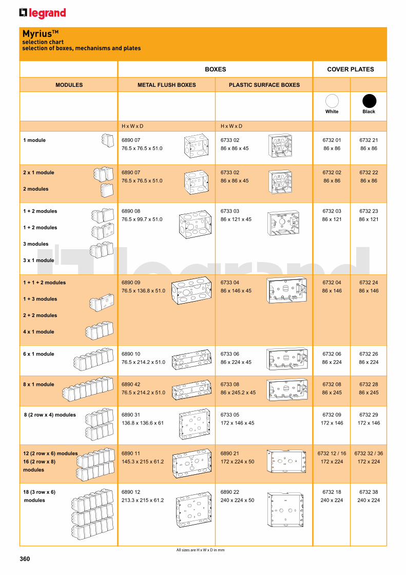
360 All sizes are H x W x D in mm BOXES COVER PLATES Myrius TM selection chart selection of boxes, mechanisms and plates MODULES METAL FLUSH BOXES PLASTIC SURFACE BOXES White Black H x W x D H x W x D 1 module 6890 07 6733 02 6732 01 6732 21 76.5 x 76.5 x 51.0 86 x 86 x 45 86 x 86 86 x 86 2 x 1 module 6890 07 6733 02 6732 02 6732 22 76.5 x 76.5 x 51.0 86 x 86 x 45 86 x 86 86 x 86 2 modules 1 + 2 modules 6890 08 6733 03 6732 03 6732 23 76.5 x 99.7 x 51.0 86 x 121 x 45 86 x 121 86 x 121 1 + 2 modules 3 modules 3 x 1 module 1 + 1 + 2 modules 6890 09 6733 04 6732 04 6732 24 76.5 x 136.8 x 51.0 86 x 146 x 45 86 x 146 86 x 146 1 + 3 modules 2 + 2 modules 4 x 1 module 6 x 1 module 6890 10 6733 06 6732 06 6732 26 76.5 x 214.2 x 51.0 86 x 224 x 45 86 x 224 86 x 224 8 x 1 module 6890 42 6733 08 6732 08 6732 28 76.5 x 214.2 x 51.0 86 x 245.2 x 45 86 x 245 86 x 245 8 (2 row x 4) modules 6890 31 6733 05 6732 09 6732 29 136.8 x 136.6 x 61 172 x 146 x 45 172 x 146 172 x 146 12 (2 row x 6) modules 6890 11 6890 21 6732 12 / 16 6732 32 / 36 16 (2 row x 8) 145.3 x 215 x 61.2 172 x 224 x 50 172 x 224 172 x 224 modules 18 (3 row x 6) 6890 12 6890 22 6732 18 6732 38 modules 213.3 x 215 x 61.2 240 x 224 x 50 240 x 224 240 x 224
Transcript
pour exemple : xxxxxxxxxxxxxxx
360All sizes are H x W x D in mm
BOXES COVER PLATES
MyriusTM selection chart selection of boxes, mechanisms and plates
MODULES METAL FLUSH BOXES PLASTIC SURFACE BOXES
White Black
H x W x D H x W x D
1 module 6890 07 6733 02 6732 01 6732 21 76.5 x 76.5 x 51.0 86 x 86 x 45 86 x 86 86 x 86
2 x 1 module 6890 07 6733 02 6732 02 6732 22 76.5 x 76.5 x 51.0 86 x 86 x 45 86 x 86 86 x 86 2 modules
1 + 2 modules 6890 08 6733 03 6732 03 6732 23 76.5 x 99.7 x 51.0 86 x 121 x 45 86 x 121 86 x 121 1 + 2 modules 3 modules 3 x 1 module
1 + 1 + 2 modules 6890 09 6733 04 6732 04 6732 24 76.5 x 136.8 x 51.0 86 x 146 x 45 86 x 146 86 x 146 1 + 3 modules 2 + 2 modules 4 x 1 module
6 x 1 module 6890 10 6733 06 6732 06 6732 26 76.5 x 214.2 x 51.0 86 x 224 x 45 86 x 224 86 x 224
8 x 1 module 6890 42 6733 08 6732 08 6732 28 76.5 x 214.2 x 51.0 86 x 245.2 x 45 86 x 245 86 x 245
8 (2 row x 4) modules 6890 31 6733 05 6732 09 6732 29 136.8 x 136.6 x 61 172 x 146 x 45 172 x 146 172 x 146
12 (2 row x 6) modules 6890 11 6890 21 6732 12 / 16 6732 32 / 36 16 (2 row x 8) 145.3 x 215 x 61.2 172 x 224 x 50 172 x 224 172 x 224 modules
18 (3 row x 6) 6890 12 6890 22 6732 18 6732 38 modules 213.3 x 215 x 61.2 240 x 224 x 50 240 x 224 240 x 224
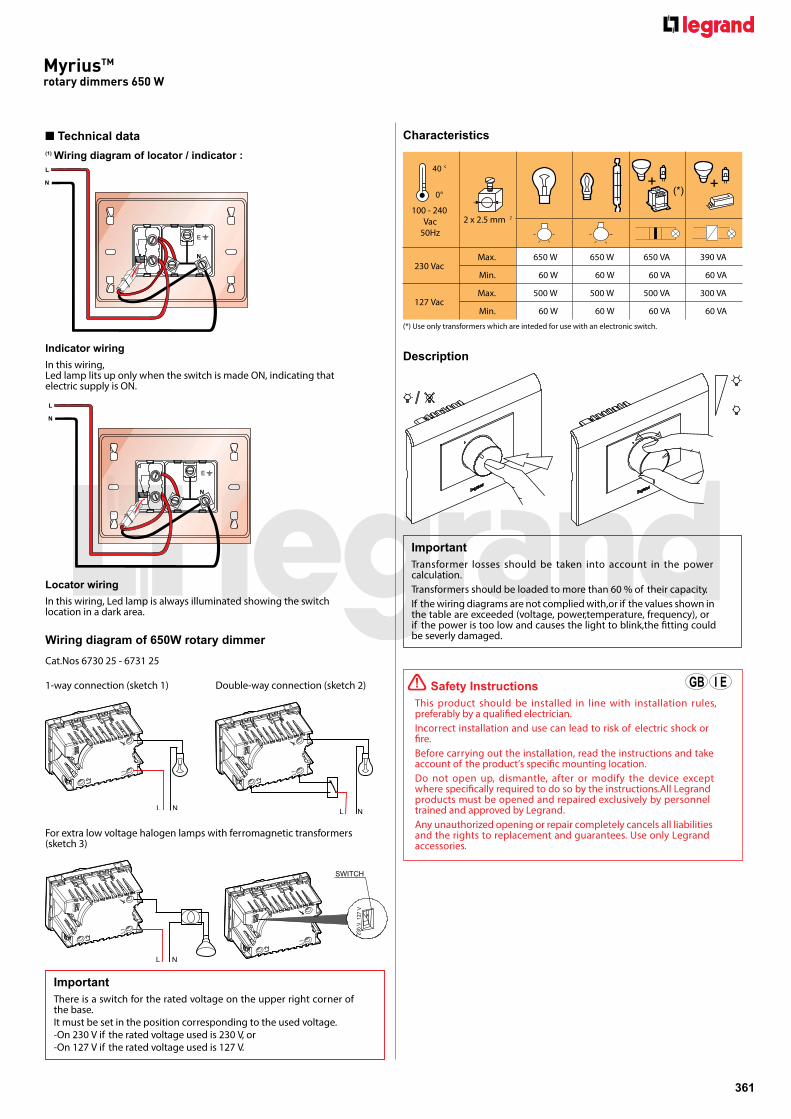
(*) Use only transformers which are inteded for use with an electronic switch.
ImportantThere is a switch for the rated voltage on the upper right corner of the base.It must be set in the position corresponding to the used voltage.-On 230 V if the rated voltage used is 230 V, or-On 127 V if the rated voltage used is 127 V.
For extra low voltage halogen lamps with ferromagnetic transformers (sketch 3)
Locator wiringIn this wiring, Led lamp is always illuminated showing the switch location in a dark area.
Technical data(1) Wiring diagram of locator / indicator :
Indicator wiringIn this wiring, Led lamp lits up only when the switch is made ON, indicating that electric supply is ON.
Description
ImportantTransformer losses should be taken into account in the power calculation.Transformers should be loaded to more than 60 % of their capacity.If the wiring diagrams are not complied with,or if the values shown in the table are exceeded (voltage, power,temperature, frequency), or if the power is too low and causes the light to blink,the �tting could be severly damaged.
! Safety InstructionsThis product should be installed in line with installation rules, preferably by a quali�ed electrician. Incorrect installation and use can lead to risk of electric shock or �re.Before carrying out the installation, read the instructions and take account of the product’s speci�c mounting location.Do not open up, dismantle, after or modify the device except where speci�cally required to do so by the instructions.All Legrand products must be opened and repaired exclusively by personnel trained and approved by Legrand.Any unauthorized opening or repair completely cancels all liabilities and the rights to replacement and guarantees. Use only Legrand accessories.
(*) Use only transformers which are intended for use with an electronic switch.
364
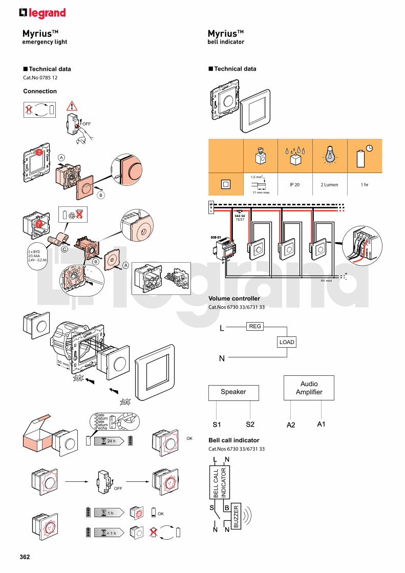
pour exemple : xxxxxxxxxxxxxxxMyriusTM
infrared sensor - 300 W
Settings
Operation
Precautions of use
! Safety InstructionsThis product should be installed in line with installation rules, preferably by a quali�ed electrician. Incorrect installation and use can lead to risk of electric shock or �re.Before carrying out the installation, read the instructions and take account of the product's speci�c mounting location.Do not open up, dismantle, alter or modify the device except where speci�cally required to do so by the instructions. All Legrand products must beopened and repaired exclusively by personnel trained and approved by LEGRAND. Any unauthorised opening or repair completely cancels all liabilities and the rights to replacement and guarantees.Use only Legrand brand accessories.
! Safety InstructionsThis product should be installed in line with installation rules, preferably by a quali�ed electrician. Incorrect installation and use can lead to risk of electric shock or �re.Before carrying out the installation, read the instructions and take account of the product’s speci�c mounting location.Do not open up, dismantle, alter or modify the device except where speci�cally required to do so by the instructions. All Legrand products must be opened and repaired exclusively by personnel trained and approved by Legrand.Any unauthorised opening or repair completely cancels all liabilities and the rights to replacement and guarantees.Use only Legrand brand accessories.
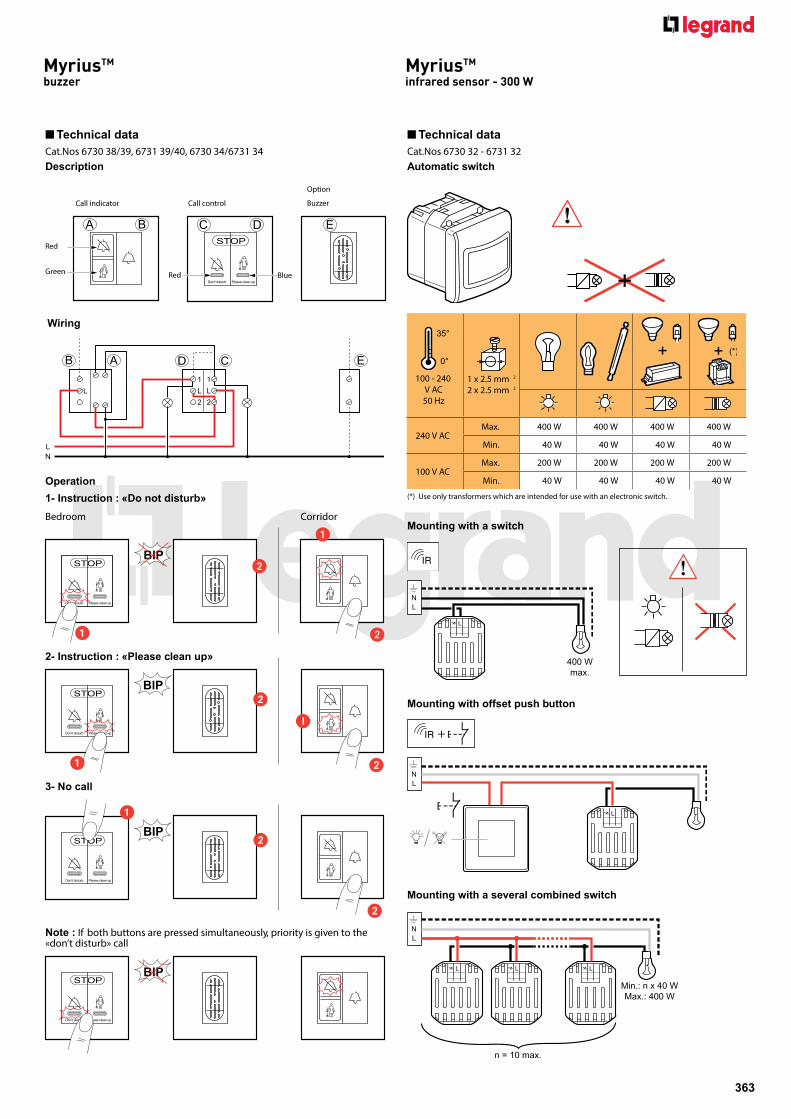
1. Incandescent bulbs.2. Halogen lamp 230 V A 3. Low voltage halogen lamps. 4. Fluorescent tube light. 5. 120 Watts Ceiling Fan (OFF + 10 Variable speed steps)
240 V AC50Hz
Max. 1 x 2.5 mm2
400 VA 200 VA 200 VA 150 VA 120 W
Utilization
0000000000000000000000000000000000000xxxxxxxx
366
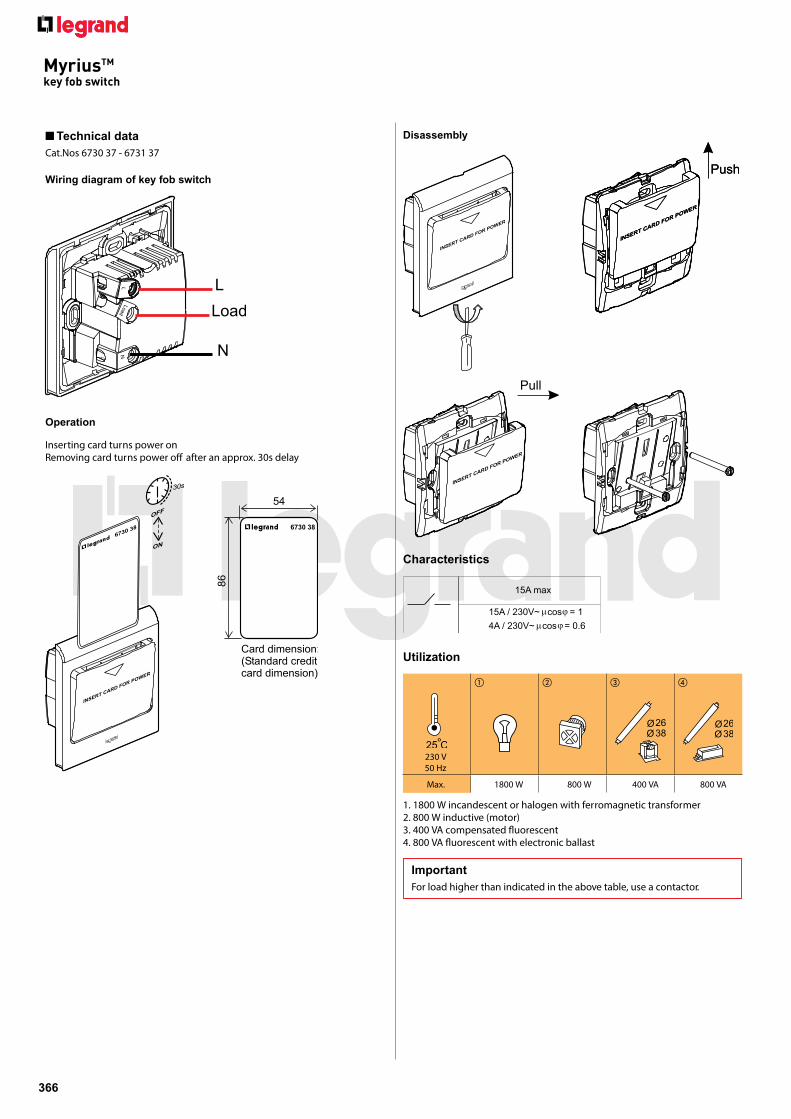
MyriusTM
key fob switch
Technical dataCat.Nos 6730 37 - 6731 37
Utilization
230 V 50 Hz
Max. 1800 W 800 W 400 VA 800 VA
ImportantFor load higher than indicated in the above table, use a contactor.
1. 1800 W incandescent or halogen with ferromagnetic transformer2. 800 W inductive (motor)3. 400 VA compensated �uorescent4. 800 VA �uorescent with electronic ballast
Disassembly
Wiring diagram of key fob switch
Operation
Inserting card turns power onRemoving card turns power o� after an approx. 30s delay
Characteristics
pour exemple XXXXXXxxxxxxxxxxxxxx
367
MyriusTM
TV/SAT/FM socket
Technical dataCat.Nos 6730 51 - 6731 51
Wiring diagram of TV/SAT/FM socket
TV/SAT/FM socket
! Safety InstructionsThis product should be installed in line with installation rules, preferably by a quali�ed electrician. Incorrect installation and use can lead to risk of electric shock or �re. Before carrying out the installation, read the instructions and take account of product’s speci�c mounting location.Do not open up, dismantle, alter or modify the device except where speci�cally required to do so by the instructions,All Legrand products must be opened and repaired exclusively by personnel trained and approved by Legrand. Any unauthorised opening or repair completely cancels all liabilities and the rights to replacement and guarantees. Use only Legrand brand accessories.
! Safety InstructionsThis product should be installed in line with installation rules, preferably by a quali�ed electrician. Incorrect installation and use can lead to risk of electric shock or �re.Before carrying out the installation, read the instructions and take account of the product’s speci�c mounting location.Do not open up, dismantle, alter or modify the device except where speci�cally required to do so by the instructions. All Legrand products must be opened and repaired exclusively by personnel trained and approved by Legrand.Any unauthorised opening or repair completely cancels all liabilities and the rights to replacement and guarantees.Use only Legrand brand accessories.
MyriusTM
audio video connector
Technical dataCat.Nos 6730 57 - 6731 57
AV connector
Wiring diagram
MyriusTM
RJ 45
pour exemple : xxxxxxxxxxxxxxx
pour exemple : xxxxxxxxxxxxxxx
370
MyriusTM
audio video connector
AV connector
! Safety InstructionsThis product should be installed in line with installation rules, preferably by a quali�ed electrician. Incorrect installation and use can lead to risk of electric shock or �re. Before carrying out the installation, read the instructions and take account of product’s speci�c mounting location.Do not open up, dismantle, alter or modify the device except where speci�cally required to do so by the instructions,All Legrand products must be opened and repaired exclusively by personnel trained and approved by Legrand. Any unauthorised opening or repair completely cancels all liabilities and the rights to replacement and guarantees. Use only Legrand brand accessories.
MyriusTM
audio video connector
Technical dataCat.Nos 6730 59 - 6731 59
Wiring diagram of projector connector
pour exemple XXXXXXxxxxxxxxxxxxxx
371
Projector connector
Terminal block legend(Connector legend)
VGA FULL PIN1 Red coax (red)6 Red braid (red ground)2 Green coax (green)7 Green braid (green ground)3 Blue coax (blue)8 Blue braid (blue ground)9 White14 Green (VS)10 Blue (HS-VS ground)13 Grey (HS)11 Brown (ID Bit 0)12 Yellow (ID Bit 1)4 Orange (ID Bit 2)15 Black (ID Bit 3)5 Red (Gnd) General ground
VGA RGB HS VS1 Red coax (red)6 Red braid (red ground)2 Green coax (green)7 Green braid (green ground)3 Blue coax (blue)8 Blue braid (blue ground)14 Yellow coax (VS)10 Yellow braid + white (HS-VS ground)13 White coax (HS) General ground
! Safety InstructionsThis product should be installed in line with installation rules, preferably by a quali�ed electrician. Incorrect installation and use can lead to risk of electric shock or �re.Before carrying out the installation, read the instructions and take account of the product’s speci�c mounting location.Do not open up, dismantle, after or modify the device except where speci�cally required to do so by the instructions. All Legrand products mustbe opened and repaired exclusively by personnel trained and approved by Legrand. Any unauthorized opening or repair completely cancels all liabilities andthe rights to replacement and guarantees. Use only Legrand accessories.
Projector connector
MyriusTM
audio video connector
pour exemple : xxxxxxxxxxxxxxx
pour exemple : xxxxxxxxxxxxxxx
372
MyriusTM
VSP
! snoitcurtsnI ytefaS This product should be installed preferably by a quali�ed electrician.Incorrect installation and use can entail risk of electric shock or �re.Before carrying out the installation, read the instructions and take account of the product’s speci�c mounting location.Do not open up the device. All Legrand products must be exclusively opened and repaired by personnel trained and approved by LEGRAND. Any unauthorised opening or repair completely cancels all liabilities and the rights to replacement and guarantees.Only use genuine accessories.
Technical data
Cat.Nos 6730 70 - 6731 70
VSP
Installation Method
Operation
230 V~
Up 1 kV
Uc (L/N - L/PE)(N - PE)
250 V~max230 V~
In (8/20) 2 kA
Icc max. 2,5 kA
IL
10A
I max (8/20). 4 kA
Make sure the power supply is disconnected before any intervention. Strictly comply with instructions for installation and use. !
Green indicator lampOperationalprotection
RecommendationRegularly check that the green LED is on.-When LED is o�, change the product