41
Power Generation and Distribution Analysis of a 5.5KVA Commercial Aircraft Electrical System Jian Huang, Scott Stanton - Ansoft Corporation Kaz Furmanczyk - Crane Aerospace & Electronics*

Power Generation and Distribution
Analysis of a 5.5KVA Commercial
Aircraft Electrical System Jian Huang, Scott Stanton - Ansoft Corporation
Kaz Furmanczyk - Crane Aerospace & Electronics*
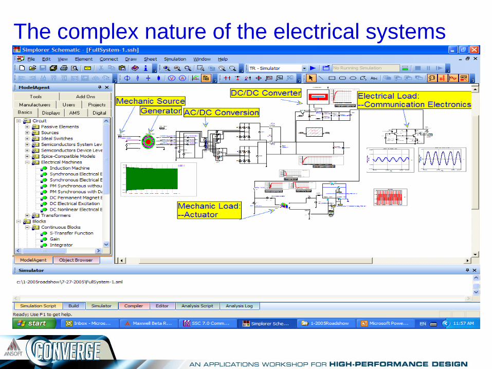
The complex nature of the electrical systems
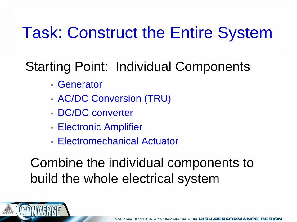
Task: Construct the Entire System
Generator
AC/DC Conversion (TRU)
DC/DC converter
Electronic Amplifier
Electromechanical Actuator
Starting Point: Individual Components
Combine the individual components to
build the whole electrical system
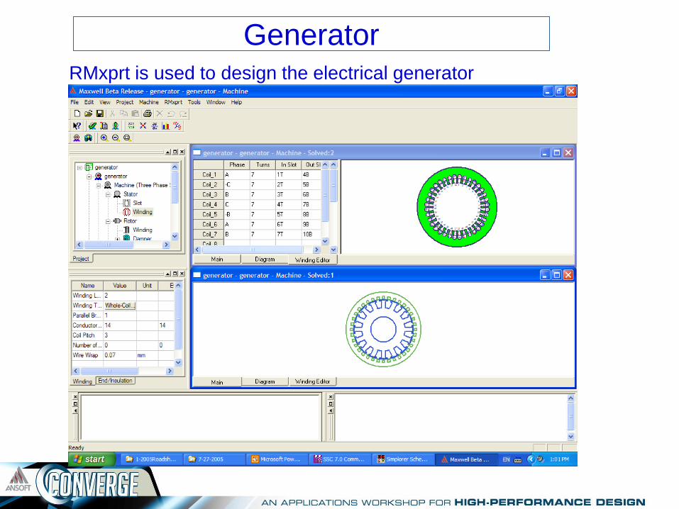
Generator RMxprt is used to design the electrical generator
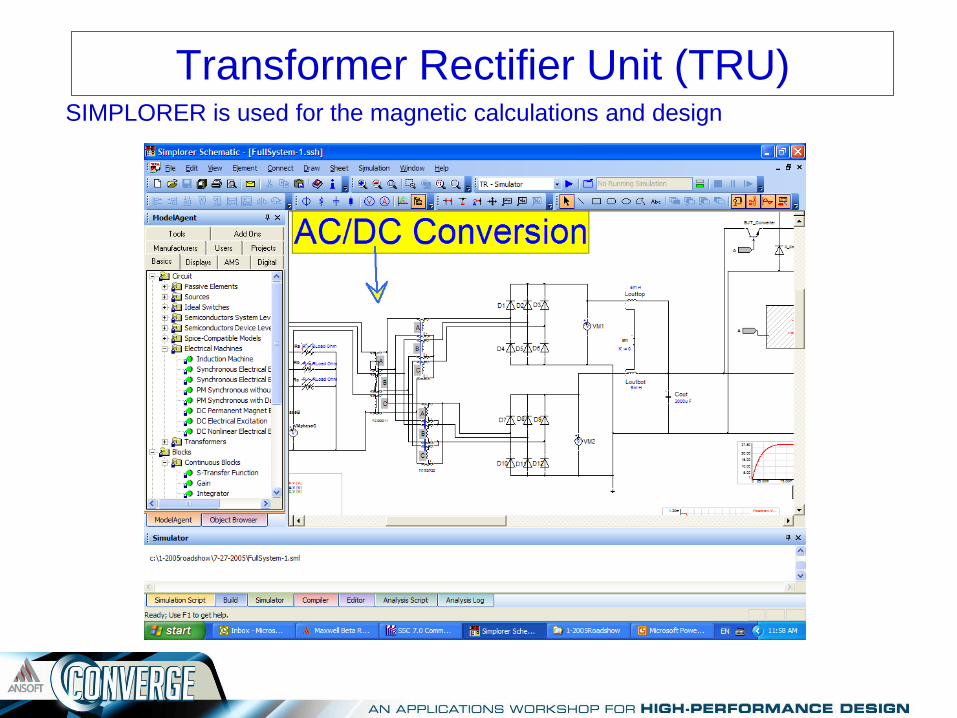
Transformer Rectifier Unit (TRU) SIMPLORER is used for the magnetic calculations and design

DC/DC converter PExprt is used to design the high frequency fly back magnetic converter

Amplifier
SIMPLORER is used for the amplifier design

Electromechanical loads Maxwell 3D and Optimetrics are used to generate electromechanical loads

Power Generation – A Systems
Engineering Perspective
Known Quantities:
Output Power: 5.5 KVA
Efficiency: 80%
Output Voltage: 115 V
Power Factor: 0.75
Rated Speed: 3000 rpm
Frequency: 400 Hz
Outside Diameter: 250 mm
Length : 60mm
Three Phase System
Total Harmonic Distortion THD: 5%
Calculated/Assumed Quantities
Number of Poles = 120 * f / n = 16
f is the frequency: 400 Hz
n is the rated speed: 3000 rpm
Steel Type: 1010
Stacking Factor: 0.97
Number of Slots: N_Poles * Phase = 48
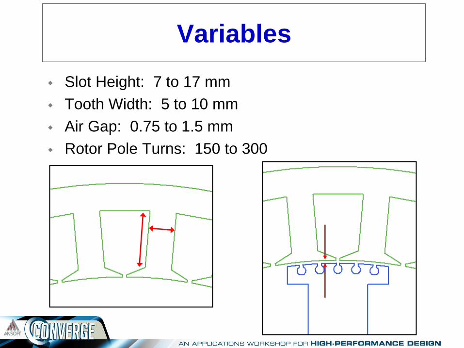
Variables
Slot Height: 7 to 17 mm
Tooth Width: 5 to 10 mm
Air Gap: 0.75 to 1.5 mm
Rotor Pole Turns: 150 to 300
RMxprt Auto Design
Stator:
Number of Turns per Phase
Number of Wires per Conductor
Wire Gauge
Rotor
Number of Wires per Conductor
Wire Gauge
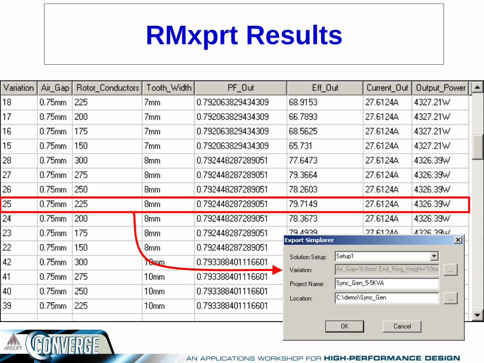
RMxprt Results
Transformer Rectifier Unit (TRU) design
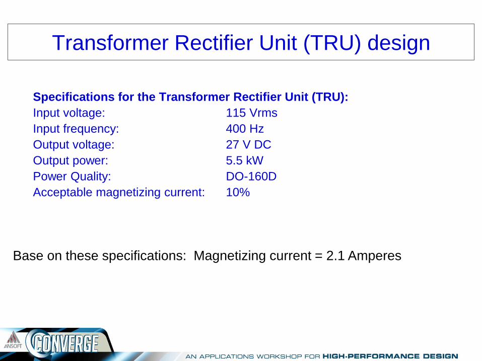
Specifications for the Transformer Rectifier Unit (TRU):
Input voltage: 115 Vrms
Input frequency: 400 Hz
Output voltage: 27 V DC
Output power: 5.5 kW
Power Quality: DO-160D
Acceptable magnetizing current: 10%
Base on these specifications: Magnetizing current = 2.1 Amperes

The Nonlinear TRU Model This nonlinear model is based on the nonlinear core material BH curve:

Parameterized electromagnetic design The core cross section and primary turns are parameterized based on the equations:
Criteria for the practical design
1. The magnetizing current will be at the same range as
specifications even at 320 Hz.
2. The operating point will be close to the core material
saturation point (to minimize weight of the TRU)

Two designs to study
Design 1: The flaw design with too small core cross section.
Design 2: The successful design with optimized parameters.
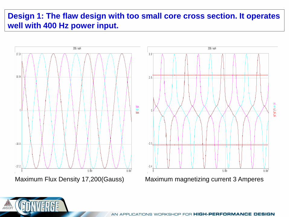
Design 1: The flaw design with too small core cross section. It operates
well with 400 Hz power input.
Maximum Flux Density 17,200(Gauss) Maximum magnetizing current 3 Amperes
- 17. 20k
17. 20k
- 10. 00k
0
10. 00k
0 8. 00m5. 00m
2DG r aphSel2
bpe. . . bpe. . . bpe. . .
- 3. 48
3. 50
- 2. 00
0
2. 00
0 8. 00m5. 00m
2DG r aphSel2
I A. . . . I B. . . . I C. . . . Tar . . . Tar . . .

Design 1: The flaw design with too small core cross section. It fails with
320 Hz power input.
The huge magnetizing current will damage the TRU very quickly
- 392. 00
395. 00
- 200. 00
0
200. 00
0 8. 00m5. 00m
2DG r aphSel2
I A. . . . I B. . . . I C. . . . Tar . . . Tar . . .
-21.60k
21.60k
0
0 8.00m5.00m
2DGraphSel2
bpeak... bpeak... bpeak...
Maximum Flux Density 21,000(Gauss) Maximum magnetizing current 395 Amperes

Design 1: The flaw design with too small core cross section. It fails with
320 Hz power input.
The amplifier fails with extreme low power supply
Amplifier fails
input output
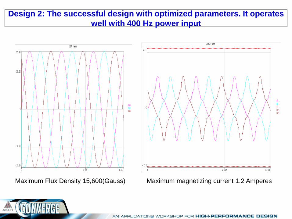
Design 2: The successful design with optimized parameters. It operates
well with 400 Hz power input
Maximum Flux Density 15,600(Gauss) Maximum magnetizing current 1.2 Amperes
- 15. 60k
15. 60k
- 10. 00k
0
10. 00k
0 8. 00m5. 00m
2DG r aphSel2
bpe. . . bpe. . . bpe. . .
- 2. 12
2. 12
0
0 8. 00m5. 00m
2DG r aphSel2
I A. . . . I B. . . . I C. . . . Tar . . . Tar . . .
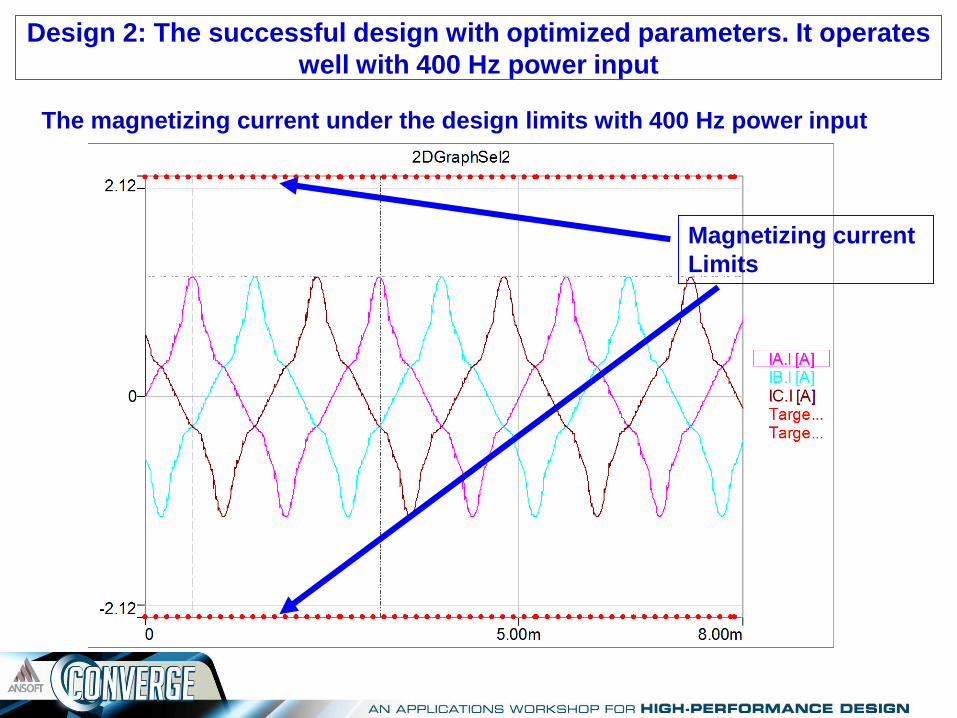
Design 2: The successful design with optimized parameters. It operates
well with 400 Hz power input
The magnetizing current under the design limits with 400 Hz power input
Magnetizing current
Limits
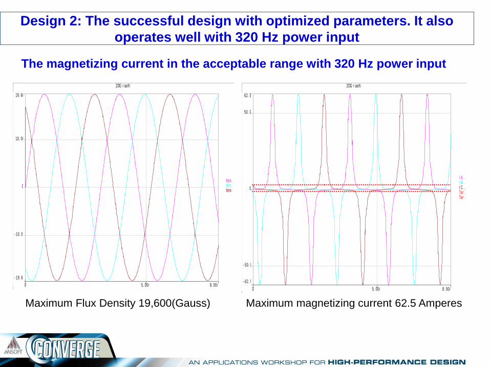
Design 2: The successful design with optimized parameters. It also
operates well with 320 Hz power input
The magnetizing current in the acceptable range with 320 Hz power input
Maximum Flux Density 19,600(Gauss) Maximum magnetizing current 62.5 Amperes
- 19. 60k
19. 60k
- 10. 00k
0
10. 00k
0 8. 00m5. 00m
2DG r aphSel2
bpe. . . bpe. . . bpe. . .
- 62. 50
62. 50
- 50. 00
0
50. 00
0 8. 00m5. 00m
2DG r aphSel2
I A. . . . I B. . . . I C. . . . Tar . . . Tar . . .
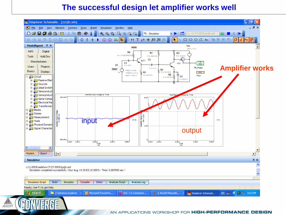
The successful design let amplifier works well
Amplifier works
input
output
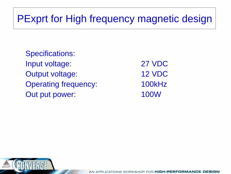
PExprt for High frequency magnetic design
Specifications:
Input voltage: 27 VDC
Output voltage: 12 VDC
Operating frequency: 100kHz
Out put power: 100W
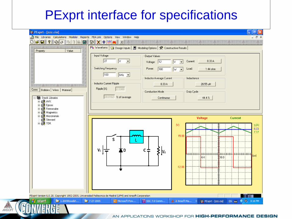
PExprt interface for specifications

PExprt optimized design
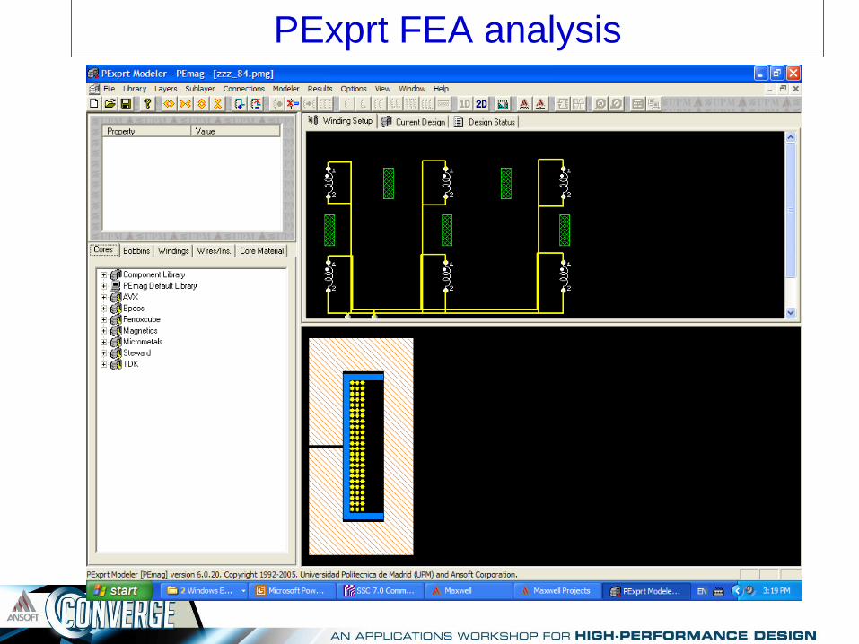
PExprt FEA analysis

Load PExprt model to SIMPLORER
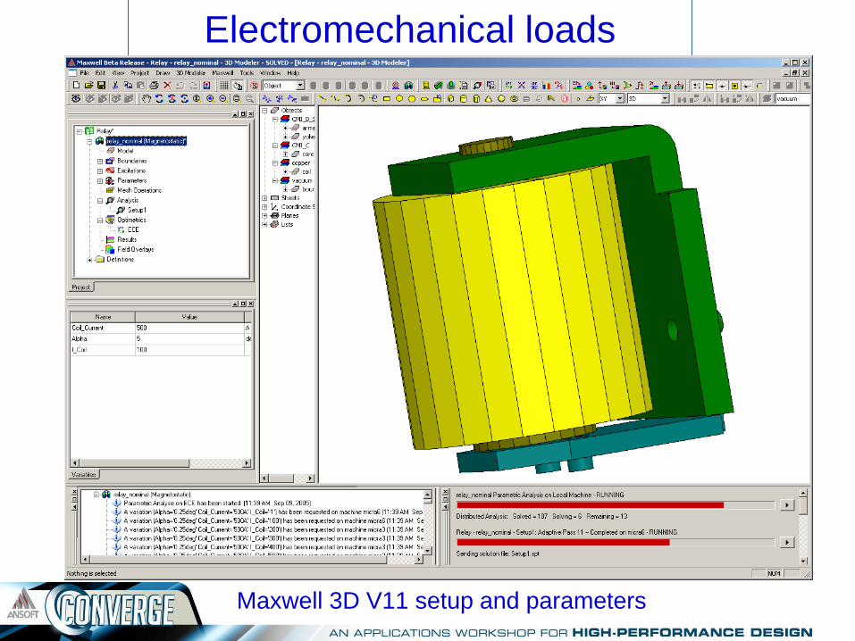
Electromechanical loads
Maxwell 3D V11 setup and parameters
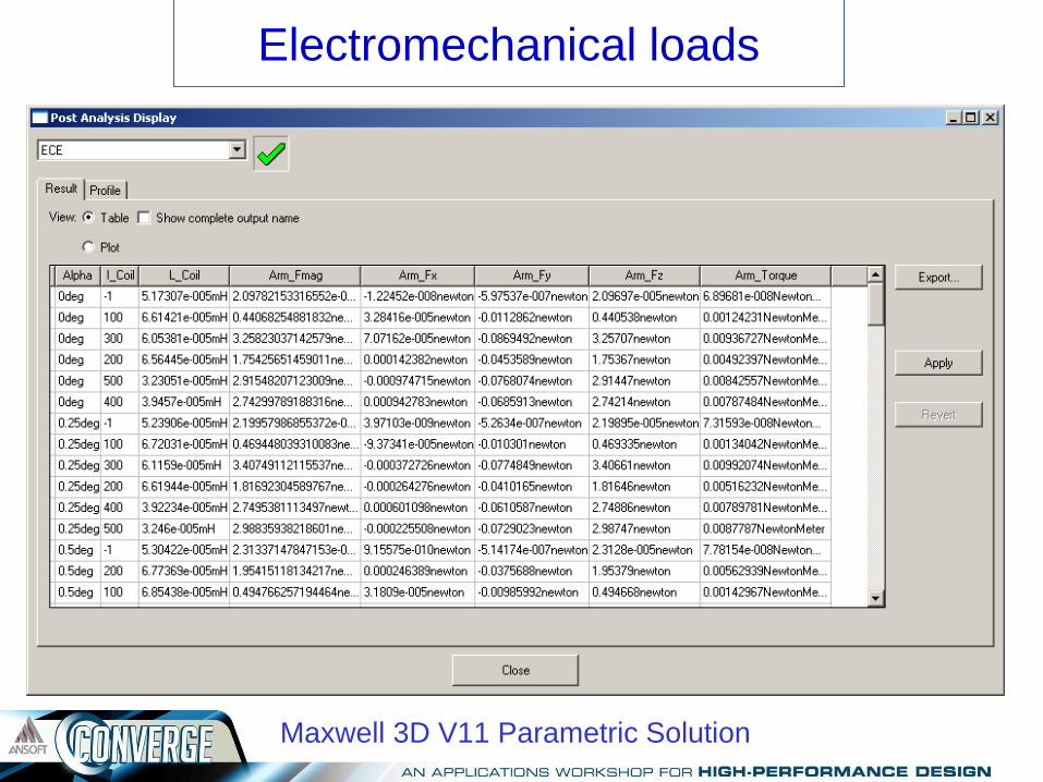
Electromechanical loads
Maxwell 3D V11 Parametric Solution

Maxwell V11 new function:
Distributed Analysis The power of ten licenses for the price of two Maxwell V11
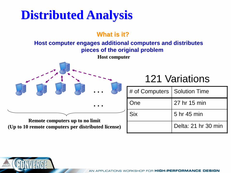
Distributed Analysis
What is it?
Host computer engages additional computers and distributes
pieces of the original problem
…
…
Host computer
Remote computers up to no limit
(Up to 10 remote computers per distributed license)
121 Variations # of Computers Solution Time
One 27 hr 15 min
Six 5 hr 45 min
Delta: 21 hr 30 min
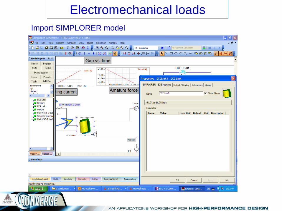
Electromechanical loads
Import SIMPLORER model
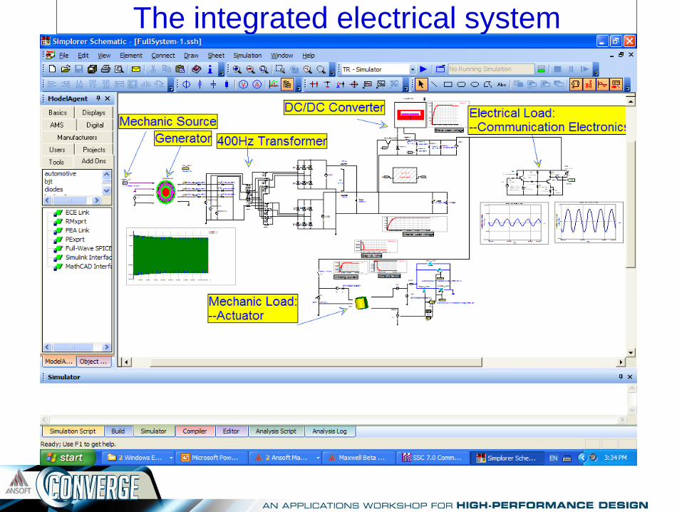
The integrated electrical system
Conclusion
1. The commercial aircraft electrical system is
constructed with individual components. Each
component is designed with a corresponding
specific tool.
2. The system performance is analyzed using
an integrated tool suite.

Any Question?
Thanks for your attention

* Crane Aerospace & Electronics specialize in design and manufacturing of power
conversion equipment for aerospace applications
Information: Web side: www.craneaerospace.com
Technical Support: Kaz Furmanczyk, Principal Engineer
Tel. 425-743-8106
e-mail: [email protected]