Power Quality and Utilisation Guide Section 8 – Distributed Generation Small Hydro Power – Investor Guide * Wladyslaw Bobrowicz , Koncern Energetyczny SA Autumn 2006 * c European Copper Institute and Koncern Energetyczny SA. Reproduction is authorised provided the material is unabridged and the source is acknowledged. 1
Transcript
Power Quality and Utilisation GuideSection 8 – Distributed Generation
The European Union has no uniform classification criteria for small hydro power (SHP).As a rule, the installed power capacity is the main classification criterion. Accordingto the ESHA (European Small Hydro Association), the European Commission and theUNIPEDE (International Union of Producers and Distributors of Electricity), SHP refersto units up to 10 MW. However, this limit is set at 3 MW in Italy, 8 MW in France, and5 MW in the UK.
A distinction is often made for the ‘Mini-hydro’ subgroup, which comprises units between100 kW and 1 MW. Sometimes the term Mini-hydro is used to refer to units in the rangeof 100-300 kW, which feed local loads not connected to the distribution network andwhich are usually located in rural areas.
2 European drivers of SHP development
The European Commission (EC) supports the development of renewable resources, in-cluding hydropower and SHP, by introducing suitable directives and recommendations. In1997, the EC published the White Paper ’Energy For The Future: Renewable Sources OfEnergy’ [1], whose main purpose was to establish suitable circumstances for the develop-ment of renewable resources. In 2001, the EU Parliament adopted 2001/77/EC Directive(RES) concerning ’the promotion of electricity produced from renewable energy sources inthe internal electricity market ’, which established the objective of producing 22.1% of thetotal electricity consumption in the Community from renewable energy sources by 2010.Following the EU’s expansion to 25 countries, this indicative objective is now set at thelevel of 21%.
The main aims of RES development are:
• to reduce environmental impacts,
• to increase the security of the power supply,
• to create sustainable energy systems.
As a rule, large hydropower station schemes involve large-scale environmental integrationactivities, which have subsequent consequences. These problems are almost non-existentin the case of SHP up to 10 MW. In general, SHP can be integrated more easily into localecosystems. Small hydro power stations require modern dedicated equipment to meet thehigh requirements regarding energy generation efficiency and simplicity and environmentalprotection.
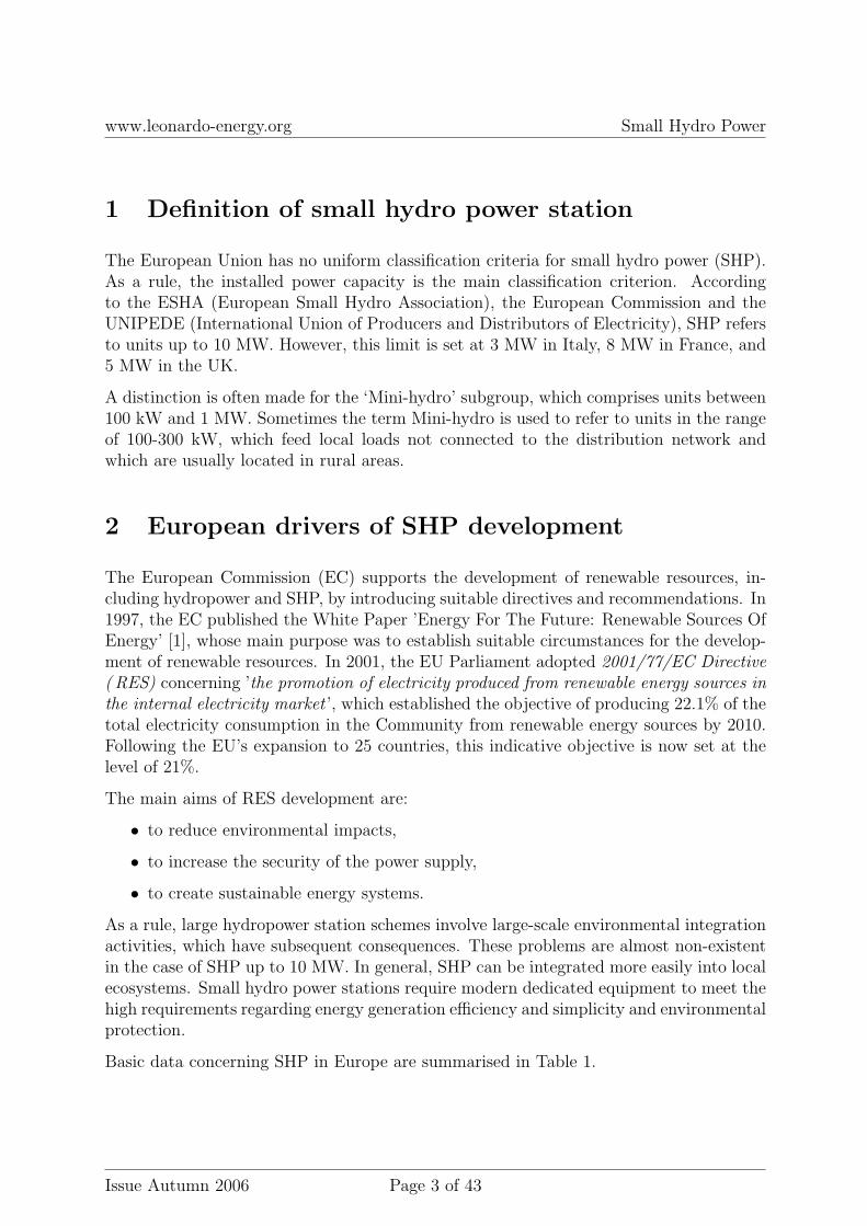
Basic data concerning SHP in Europe are summarised in Table 1.
EU - 15 EU - 10 EU – new candidatesQuantity 14 000 2 800 400Installed power 10 GW 830MW 600 MWAverage installed power 700 kW 300 kW 1.6 MWAnnual production 40 TWh 2,3 TWh 1.4 TWh
Table 1: EU data on SHP potential
In the EU-25, the SHP potential is concentrated mainly in Italy (21%), France (17%),and Spain (16%). New SHP resources are located primarily in Norway and Switzerland[2, 3].
The EU objective for SHP is 14GW of installed capacity and 55 TWh/a of electricalenergy production by the year 2010 (White Paper).
Special attention should be given to modernising existing installations: it is estimatedthat more than 70% of today’s installations are over 40 years old. The European SmallHydropower Association (ESHA) represents this business sector.
3 Why SHP?
There are many reasons for the great interest in small hydro power. The potency ofthe arguments is relative to the type and scale of the benefits. The most importantconditions to be considered by the investor / producer are stable incomes and a relativelyhigh rate of return. These conditions are fulfilled by adequate support mechanisms (e.g.green certificates). From the environmental point of view, reducing CO2 is of greatimportance as well as helping preserve catchment areas. Very often, abandoned dams arerestored and some micro retention objects are renewed, which improves the soil moistureconditions in the adjacent areas. SHP growth can be a valuable part of the so-called‘region sustainable development policy’ widely supported by the EU. The main aim ofthis policy is to ensure supply of energy while protecting the environment and maintainingenergy quality parameters at prices acceptable to the general public.
SHP projects should not have to cover the overall cost of new dam construction andhydrologic equipment, as such financial burdens could cancel the economic efficiency ofthe entire project. Extra benefits from SHP development can be achieved as a result ofa synergy of efforts on the local, national and European levels. The adequate financialstreams should be a part of this.
Why SHP? Because everyone benefits, but for the investor it could meanbusiness
In order to secure return on investment, every potential investor should accurately definethe basic parameters of the investment: in particular, the scale of the investment, potentialproblems, potential sources of financing, rate of return, basic categories of costs, andoperating costs. Therefore, initially, a simplified feasibility study of the project should bedeveloped, which contains the balance of costs and expected benefits. The primary basisof such a preliminary analysis is an accurate estimation of hydro-technical parametersat the site of the power station. Hence, measurement data from competent hydrologicalservices should be used. Where there is no such data, flows can be estimated (interpolated)on the basis of measurements in other points of the catchment area, or the investor canperform his own measurements. This, however, may prove to be too expensive. One of theelements in estimating hydro-power potential is the determination of the Flow DurationCurve. It is also important to become familiar with the conditions of the connection tothe grid and to evaluate the project execution schedule and exploitation conditions of theinvestment.
The initial analysis should answer the following questions:
Potential and kinetic energy of a mass of water flowing from a higher level to a lower levelcan be converted into electrical energy. The hydrological potential of water is determinedby two parameters: head (H) and flow (Q). Head is crucial, especially for SHP. It is notreally necessary to have the water flowing rapidly.
The Gross Head (H) is the maximum difference between the levels of falling water. Theturbine’s actual head is less than the maximum, due to losses caused by friction withconstruction elements and the internal friction of the water. Sites are classified accordingto head size:
• ’low head’, for H <10 m,
• ’medium head’, for H ranging between 10 - 50 m,
• ’high head’, for H >50 m.
The Flow (Q) - expressed in m3/s - is the volume of water flowing through a givencross-section of the stream per second.
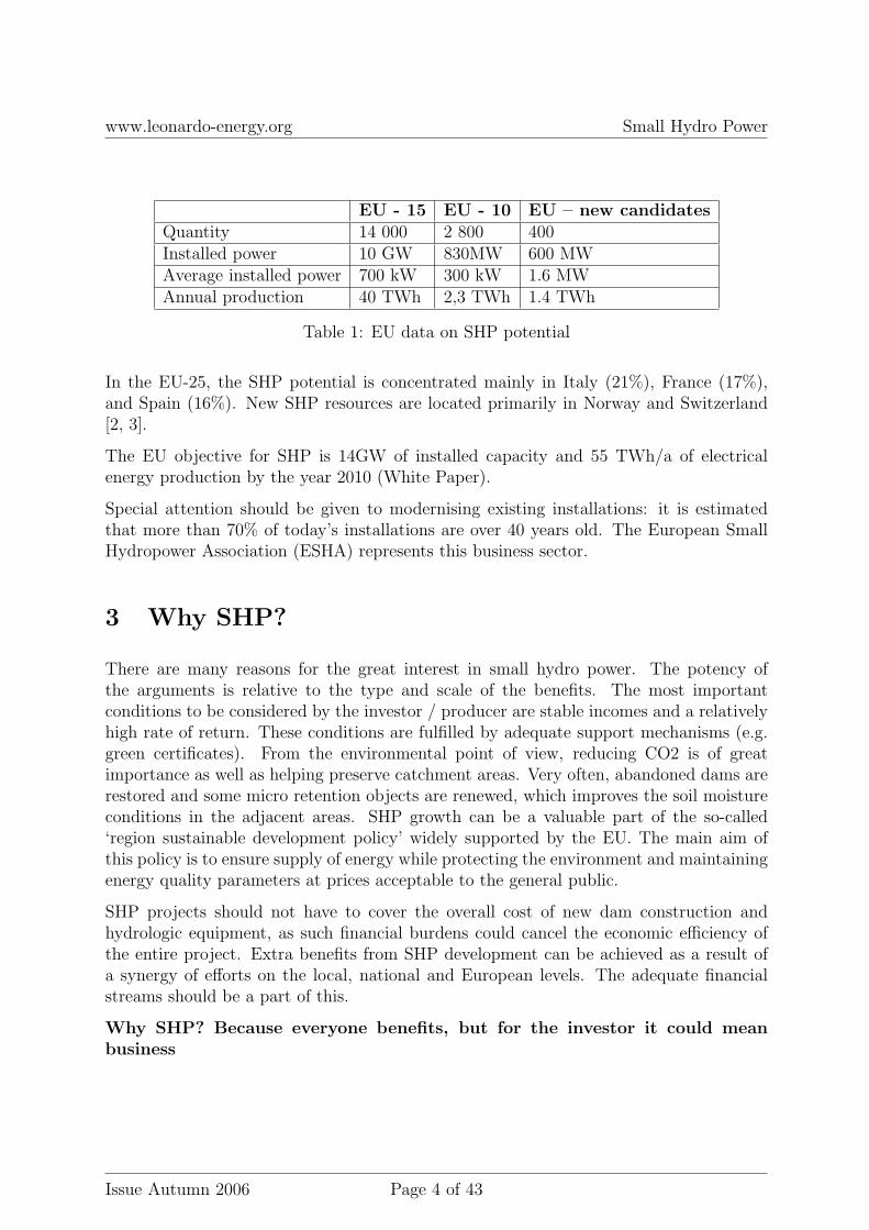
Electrical power and energy Energy is the amount of work done in a fixed timeinterval. A turbine converts water pressure energy into the mechanical energy of theturbine shaft, which drives a generator to produce electrical energy. The energy unit isJoule (J); and the electrical energy unit is the kilowatt-hour (kWh): 1 kWh = 3600 J.Power is the amount of energy per time interval unit. Therefore, the electrical power ofthe generator is defined by the following formula:
P = η · ρ · g ·Q ·H (1)
where:
P - electrical power [W],η - hydraulic efficiency of the turbine,ρ - water density, .ρ=1000 kg/m3,g - acceleration of gravity, g=9.81m/s2,Q - flow – volume of water flowing through the turbine in time unit, [m3/s],H - head – effective pressure of water flowing into the turbine [m].
Turbine technology is a mature technology characterised by relatively high efficiency. Theefficiency of large hydropower units reaches the level of 80 - 90%. The efficiency of smallerhydro units (<100kW) is about 10-20% less. When estimating the power of small hydro
units (e.g. micro-turbines), turbine efficiency is usually assumed to be .η = 70-75%. Thus,electrical power can be estimated by the following formula:
P ≈ 7÷ 8 ·Q ·H (2)
P = [kW], Q = [m3/s], H = [m]. To estimate energy, assume 4 500 working hours withthe power output defined by equation 2:
E ≈ 4500 · P (3)
where: E = energy [kWh].
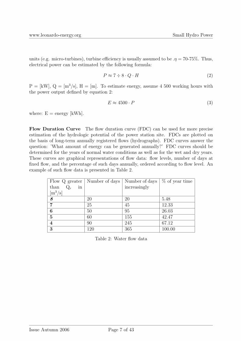
Flow Duration Curve The flow duration curve (FDC) can be used for more preciseestimation of the hydrologic potential of the power station site. FDCs are plotted onthe basis of long-term annually registered flows (hydrographs). FDC curves answer thequestion: ’What amount of energy can be generated annually?’ FDC curves should bedetermined for the years of normal water conditions as well as for the wet and dry years.These curves are graphical representations of flow data: flow levels, number of days atfixed flow, and the percentage of such days annually, ordered according to flow level. Anexample of such flow data is presented in Table 2.
Figure 1: Flow Duration Curve (probability of flows greater than Qr)
Energy is a measure of power maintained at a fixed level over a particular time interval.Hence, the FDC curve determines the probability of the event: ’Over how many days willa given level of flow be attained ’. The area below the FDC curve is the amount of energygenerated. This area should be as large as possible. Good flow systems are characterisedby a rather flat curve high above the X-axis, which corresponds to stable and uniformflows over all the days of the year.
Analysis of water resources and production – chosen elements A basic knowl-edge of fluid mechanics and hydraulic equipment engineering is useful for estimating thewater potential. The energy of the jet of water flowing through a pipe is specified byBernoulli’s rule for so-called laminar flow. Without details:
The energy of the water defined by Bernouli’s rule is the sum of:
• potential energy described by head,
• energy of a pressure,
• kinetic energy.
In practice, during the flow some energy is lost due to friction against the walls of thechannel and specific internal friction determined by the viscosity of the liquid. These
energy losses can be calculated by specialists. The friction coefficient of the channel walls(determined by the material the wall is made of) is of great importance. For the laminarflows and tubular draught of inlet water, the energy losses are proportional to the speedof the water and inversely proportional to the square of the diameter of the pipe.
In the cases of non-laminar flows, the friction coefficient for the energy losses in the watercan be calculated from the Moody graph [4]. This parameter is an empirical function ofthe quantity e/D, where e is the so-called roughness factor and D is the diameter of thechannel. The value of the roughness factor is determined empirically: e.g., for new steele=0.025, for wood e=0.6, for concrete e=0.18. The energy losses for channels with wallsmade of wood can be significant, and they can be even greater on various kinds of bendsand valves. In this case, the diameters of the channels should be enlarged.
Knowledge about the places where energy is lost and about the possibilities ofreducing these losses - taking the local conditions of the plant site into account- is one of the major determinants of project optimisation.
Water flows in open canals For the purposes of water flow analysis and the properestimation of the flow (Q) in the canals , it is very important to determine the averageflow velocity.
The distribution of the flow velocity depends on the flow profile. Examples of differentprofile shapes are shown in Figure 2.
3m3/s 2m3/s 1m3/s
Figure 2: The distribution of water velocity for various flow profiles (iso-velocity lines)
For the steady flows (i.e. for which the depth, cross-section, and velocity in a given placedo not change), the flow velocity can be calculated using more or less complicated math-ematical formulas [4]. This velocity depends on channel roughness parameters, shapes(hydraulic radius), and the slope of the canal.
One of the major challenges is the selection of canal parameters - e.g. the depth or levelof water in the canal.
One of the most important parameters of hydro power stations is the head, which is thedifference in meters between the level of inlet water (i.e. useful water) and the level ofoutlet water.
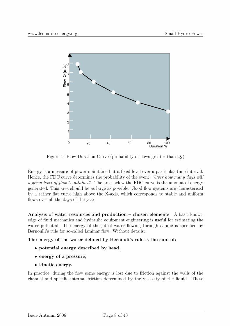
A scheme of a hydro power station with a high head is shown in Figure 3.
The construction of a power station depends on the head profile and geomorphology ofthe location. These parameters determine the type of turbines to be used, their poweroutput, the number required and their configuration. Depending on the way the waterenters the hydro station and on the location of the hydro technical objects, hydro powerstations can be classified into three groups:
• near dam,
• with canal derivation,
• with pipe derivation.
1
1
2
2
3
3
9
4
8
7
4
7
5
5
6
6
8
Figure 3: Hydro power station scheme with high head (1- lake, 2- dam, 3- canal, 4- tunnel,5- intake, 6- penstock, 7- powerhouse, 8- outlet, 9- river)
Small investors are generally interested in the near-dam power stations or in the stationswith pipe derivation. Hydro power stations with canal derivation are usually much larger,attracting larger institutional investors. Near-weir SHPs are usually built in the lowlandswhere the natural head is rather small. They often work as a damming element. Near-weirhydro power station turbines are often installed in dam pillars. Such a solution allows forsavings on building materials. Turbines can be built in the dam construction – in this
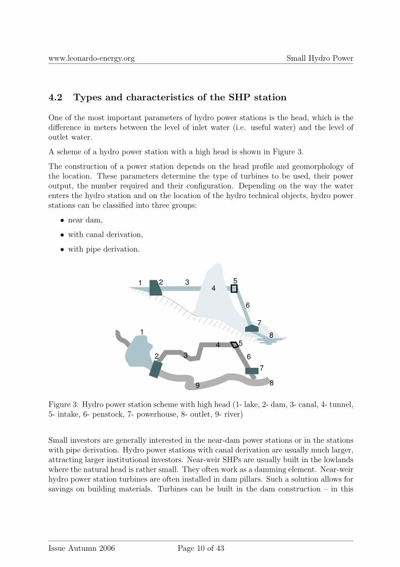
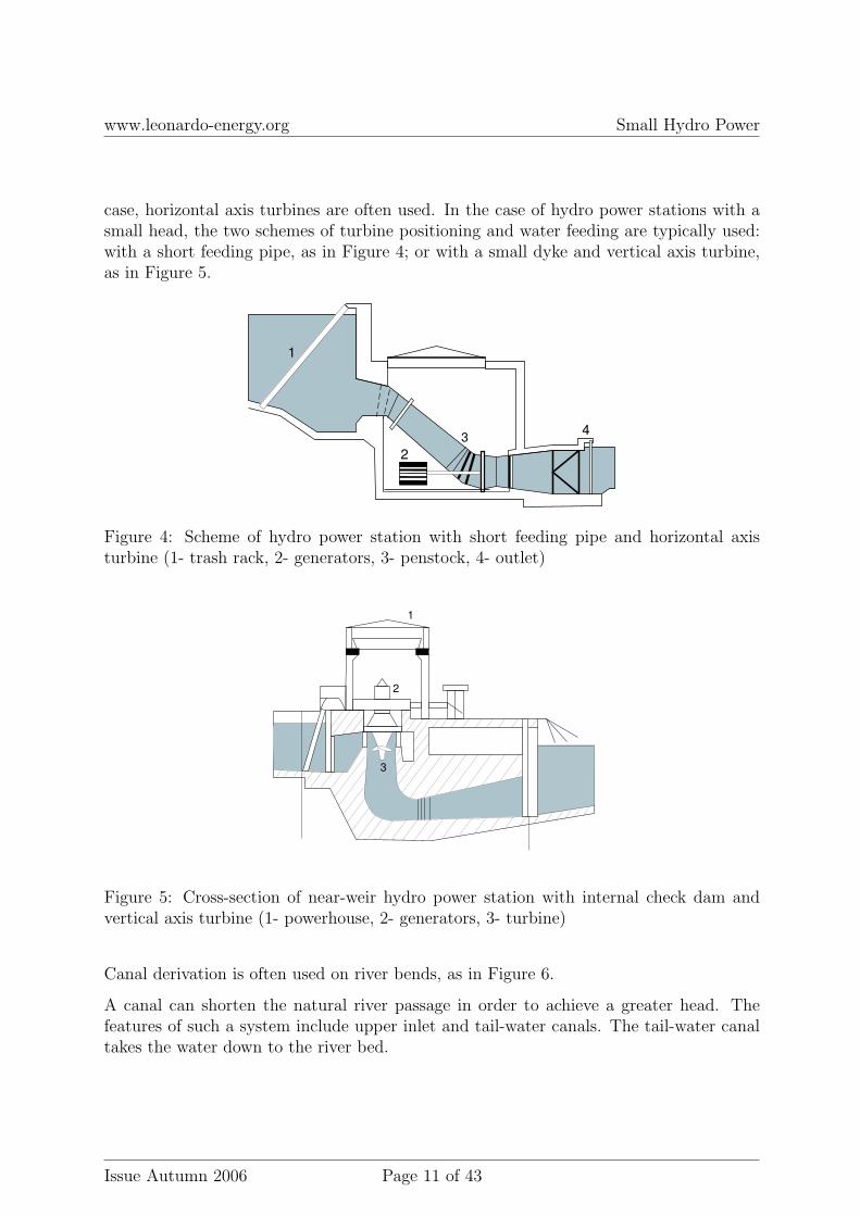
case, horizontal axis turbines are often used. In the case of hydro power stations with asmall head, the two schemes of turbine positioning and water feeding are typically used:with a short feeding pipe, as in Figure 4; or with a small dyke and vertical axis turbine,as in Figure 5.
1
2
34
Figure 4: Scheme of hydro power station with short feeding pipe and horizontal axisturbine (1- trash rack, 2- generators, 3- penstock, 4- outlet)
1
2
3
Figure 5: Cross-section of near-weir hydro power station with internal check dam andvertical axis turbine (1- powerhouse, 2- generators, 3- turbine)
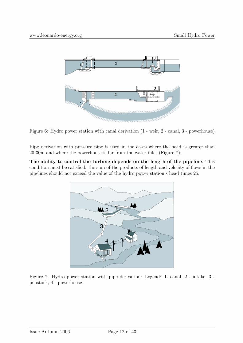
Canal derivation is often used on river bends, as in Figure 6.
A canal can shorten the natural river passage in order to achieve a greater head. Thefeatures of such a system include upper inlet and tail-water canals. The tail-water canaltakes the water down to the river bed.
Figure 6: Hydro power station with canal derivation (1 - weir, 2 - canal, 3 - powerhouse)
Pipe derivation with pressure pipe is used in the cases where the head is greater than20-30m and where the powerhouse is far from the water inlet (Figure 7).
The ability to control the turbine depends on the length of the pipeline. Thiscondition must be satisfied: the sum of the products of length and velocity of flows in thepipelines should not exceed the value of the hydro power station’s head times 25.
12
3
4
Figure 7: Hydro power station with pipe derivation: Legend: 1- canal, 2 - intake, 3 -penstock, 4 - powerhouse
Near-dam hydro power stations In the case of large heads, between 30 - 100 m, near-dam hydro power station schemes can be considered. They are often incorporated intothe dam construction to form an integral complex. The pipelines are generally arrangedin a reinforced concrete gallery.
Figure 8: Illustration of near-dam hydro power station
1 2
3
4
Figure 9: Typical scheme of near-dam hydro power station (Legend: 1- overflow, 2- pipe,3- powerhouse, 4- dam)
Turbine technology and parameters Selecting the suitable type of turbine for spe-cific local circumstances is the key to success. This selection depends mainly on the valuesof the water stream’s head and flow. Other important parameters to be taken into ac-count include the assumed speed of the turbine and the ability to work in states of lowerflows. Due to the different mechanisms used in the energy conversion process, two typesof turbines can be distinguished: impulse turbines, which take advantage of the velocityenergy of water; and reaction turbines, which make use of the pressure energy of water.
Energy parameters of the turbine The state of turbine movement is determinedmainly by the following energy parameters: head H [m], turbine flow Q [m3/s], power Pt
[kW], and rotational speed of turbine ηt [rev/min]. One can distinguish between levelling(gross) head Hn and usable (net) head Hu. The gross head is the maximum availablevertical fall of the water, from the upstream level to the downstream level. Net head isthe difference in energy between the intake level and the tail-water level.
Turbine flow Q defines the volume of water flowing into the turbine in the time unit,including all leakages and water taken into the system that decrease the pressure on theaxis.
The theoretical turbine power Ptdepends on the net head and flow:
Pt = 9.81 ·Qt ·Hu[kW ] (4)
The available power of the turbine Pu is the power on the turbine shaft, which dependson the theoretical power and the efficiency of the turbine η as defined by formula 1.
The efficiency of the turbine is the ratio of the available power to the net power. Thisefficiency is the product of the volume efficiency ηv, hydraulic efficiency ηh, and mechanicefficiency ηm:
ηt = ηv · ηh · ηm (5)
The volume efficiency is affected by the volume losses resulting from fissure leaks andleaks in the rotor relief system. The hydraulic efficiency is affected by the losses resultingfrom the water striking the turbine blades, whirls at the discharge edge, and flows throughthe blade channels.
One of the essential elements in estimating SHP productivity is the proper calculationof power on the turbine shaft. The power depends on the head, water speeds at the
upper and lower basins, and the losses resulting from leaks and the water flows throughhydraulic equipment.
For the initial, simplified calculation, formula 1 can be used.
Mechanical losses are caused mainly by the friction of the shaft against the turbine bear-ings and in glands and by the friction of rotating elements in the water. The hydraulicefficiency generally ranges from ηh=0.88-0.95, whereas the mechanical efficiency of theturbine is in the range of ηm=0.98-0.99. The efficiency of the generators can be estimatedas ηg=0.94-0.97, and that of the power output system as ηu=0.98-0.99.
Types of turbines The head and flow at the SHP site are critical factors for selectingthe turbine type. Other factors to be taken into consideration when selecting the turbineinclude:
• depth of the turbine seating in the SHP’s hydro-technic construction,
• efficiency,
• costs.
Pelton turbine Impulse turbines use the water’s velocity to move the shaft and unloadthe water pressure to the atmospheric pressure. The turbine rotor consists of blades inthe shape of buckets mounted around the wheel.
Figure 10: Pelton turbine: a) idea of operation, b) turbine
Impulse turbines are mainly used at the high heads A representative of thisgroup is the Pelton turbine, which is usually used where the high head ranges between30 - 400 m. Pelton turbines can be mounted on both horizontal and vertical shafts. Thewheel and the number of discharge jets can be varied to create different solutions. Ingeneral, these turbines can work in a wide range of flow levels - from 5 to 100%.
Banki-Michell turbine Flow turbines are usually shaped like a cylinder, with bladesmounted in the special chamber or directly in the derivation canal. The constructionof the blades often enables doubly effective flow through the blades, which improves theefficiency of the turbine.
Banki-Michell turbines can have discharge capacity from 20 dm3/s to 10m3/s and theyare used at heads ranging from 1 to 200 m.
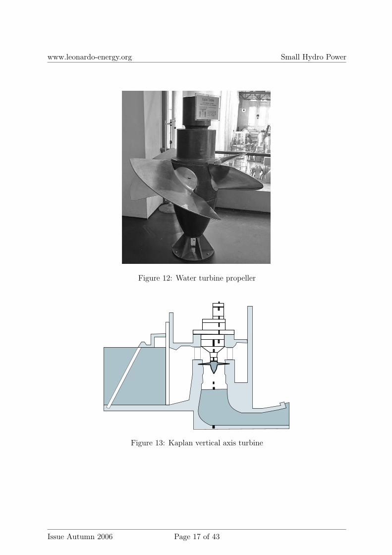
Kaplan turbine Reaction turbines generate power using both the pressure and themovement of the water. The driving mechanism is submerged in the water. The waterstream flows over the blades, not hitting them directly. As compared to impulseturbines, reaction turbines are generally used at sites with a small head andgreater flow. Propeller turbines belong to this class. Propeller turbines have their driveelement equipped with three or six blades, which have uniform contact with the water.The blades’ angle of contact is adjustable.
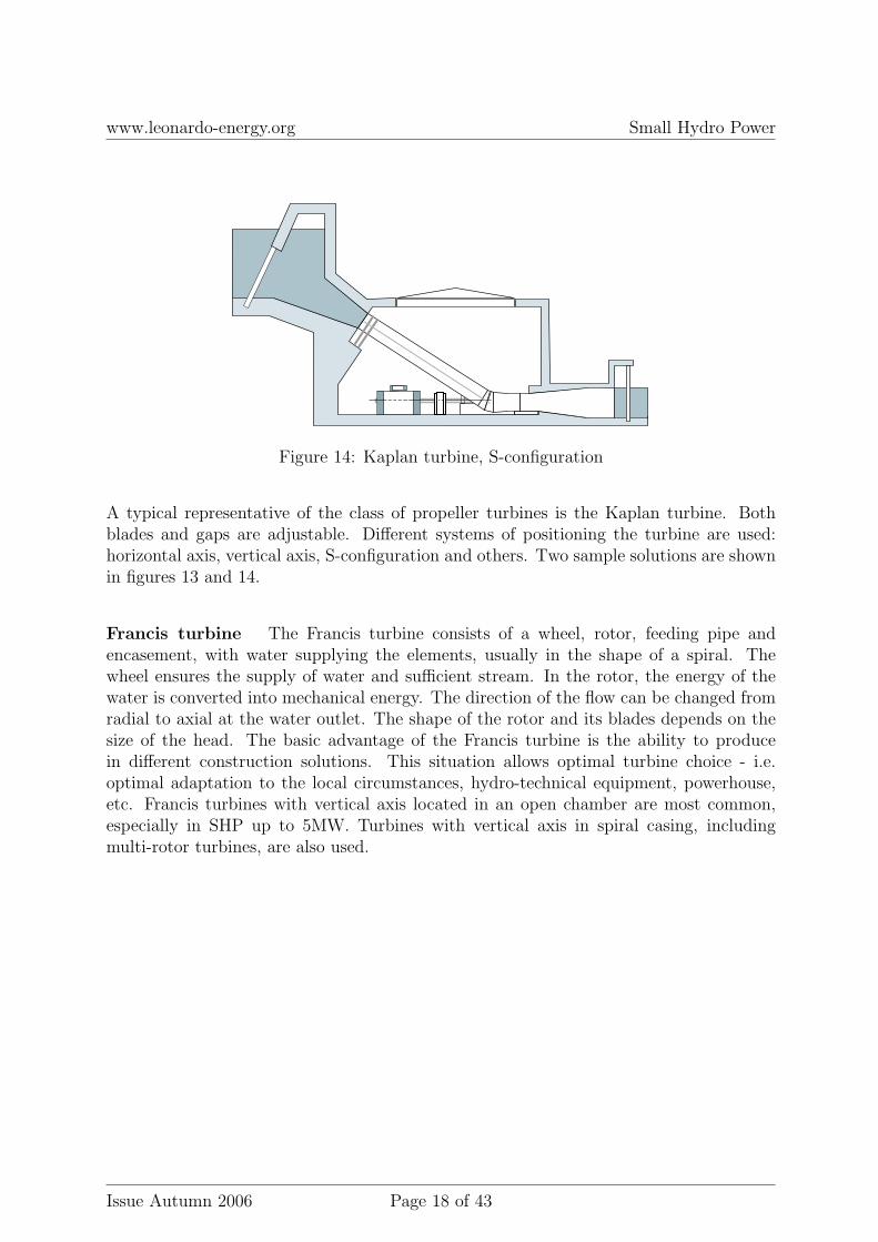
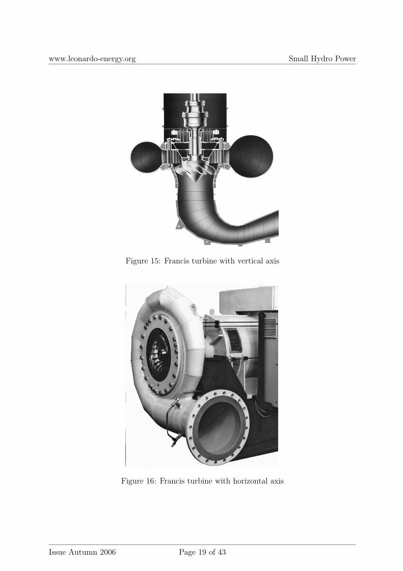
A typical representative of the class of propeller turbines is the Kaplan turbine. Bothblades and gaps are adjustable. Different systems of positioning the turbine are used:horizontal axis, vertical axis, S-configuration and others. Two sample solutions are shownin figures 13 and 14.
Francis turbine The Francis turbine consists of a wheel, rotor, feeding pipe andencasement, with water supplying the elements, usually in the shape of a spiral. Thewheel ensures the supply of water and sufficient stream. In the rotor, the energy of thewater is converted into mechanical energy. The direction of the flow can be changed fromradial to axial at the water outlet. The shape of the rotor and its blades depends on thesize of the head. The basic advantage of the Francis turbine is the ability to producein different construction solutions. This situation allows optimal turbine choice - i.e.optimal adaptation to the local circumstances, hydro-technical equipment, powerhouse,etc. Francis turbines with vertical axis located in an open chamber are most common,especially in SHP up to 5MW. Turbines with vertical axis in spiral casing, includingmulti-rotor turbines, are also used.
Kinetic turbines Kinetic turbines are classic cross-flow systems with the so-called freeflow. The kinetic energy of the flowing water is converted into electrical energy. Inthis case, potential energy resulting from the head is small. The advantage of suchsolutions is that they do not require any additional canals or major hydro-technical works. Existing hydro-technical structures - such as bridges, dams, weirs, andcanals - are suitable for setting up such a hydro power station.
Type ofturbine
Range of speed [rpm] Range of head[m]
Kaplan
L 350-500 30-40M 501-750 10-30F 751-1100 ≤ 10
Francis
L 50-150 110-300M 151-251 50-110F 251-450 ≤ 50
Pelton
L 2-15 1000-1300M 16-25 700-1000F 26-50 100-700
Banki-Michell 30-200 5-100
Table 3: Classification of turbines according to speed and head
L - low-speed turbine,
M - medium-speed turbine,
F - fast-speed turbine
4.4 Electrical diagram, automation and protection
The circuitry of the hydro power station usually consists of a generator circuit and a sta-tion service circuit, which are connected to the bus-bar. The bus-bar is usually connectedto the power grid system through the power output line and transformer. The main loadsconnected to the station service circuit include:
The station switch gear can be equipped with a metering system to measure power loadand output, a hydro-generator control system and a reactive power compensation system.The battery of capacitors should be switched on/off automatically after the main circuitbreaker has been switched on/off.
The hydro-power station can be fully automated with the full control of the hydro-generator according to the amount of water available to maximise the production ofelectrical energy.
In the case of isolated island operation, the control of flow through the turbine is carriedout to stabilize the speed of the generator. The speed controller is used in this case.Controllers with a centrifugal sensor of rotation speed are usually used in SHP stations.In the case of grid connection, the power controller is used, which cooperates with thesensor of the top water level. The frequency in this case is maintained by the power grid,and the aim of the controller is to stabilize the top water level.
The automation of the hydro power station should include:
• hydro generator emergency shut-off,
• monitoring of hydro generator operation and signalling of emergency states,
• control of the angle of the wheel blades in function of the top water level,
• automatic re-connection of hydro generator to the grid.
Many SHP stations are quipped only with the simple and absolutely necessary automaticcontrol and protection systems. This situation is improving because new micro-processorcontrol devices and relatively cheap automation systems are now available on the market.More and more investors realise the need to install modern and efficient control systems.As SHP stations are often built in remote areas, this is one of the reasons for focusingthe attention of investors on remote control systems. Such systems should be able tocontinuously optimise the generation process without any staff intervention, which wouldenable the maximisation of profits. The factors directly increasing the economic efficiencyof hydro power stations - and thus justifying the necessity of applying modern controlsystems - include the following:
• reduction of SHP station downtime after emergency shutdown (e.g. as a result ofvoltage collapse in the electrical grid) through automatic start-up of the generatorand its reconnection to the grid,
• continuous maintenance of the nominal top water level by changing the turbineopening, and continuous maximisation of the output power for a given water flow,
• monitoring of the generator’s operational parameters to identify and properly reactto emergency states and, consequently, extending the failure-free working time of
The necessity to maximise efforts to use available resources and to develop technologyoffers an acceptable return on investment period. The investment in automation andcontrol systems yields a return on investment period of 1 to 2 years. This period isshorter in the case of larger power stations and may be longer for smaller hydro powerstations.
Various media are used for remote transmission, including radio. The use of mobile phoneswith digital file transmission (GPRS) is a quite popular solution.
The automatic protection and control systems for the network, circuits and equipmentof SHP stations are usually installed within the minimum scope required to meet therequirements for the technical conditions of the connection and to ensure the correctoperation of the hydro power station.
The use of asynchronous generators, or even asynchronous engines as generators, in SHPstations requires resolving unusual problems, such as those associated with overheatingof mechanical elements.
Protection of power network Every power station, including SHP, is equipped withprotection systems. The basic types of protection used in SHP stations include:
• Over-frequency protection (activated when frequency exceeds the upper-frequencylimit).
• Under-frequency protection (activated when frequency drops below the lower-frequencylimit).
• Over-voltage protection.
• Under-voltage protection.
• Protection from voltage dips on the low voltage bus-bar.
An initial step in the SHP project analysis should cover these three basic areas:
1. determination of available water resources, including annual energy for differentaverage states of stream (i.e. for wet, medium and dry years).
2. determination of the investment range, obtaining applicable permissions and licencesfrom the competent water service, local or regional administration, environmentprotection.
3. determination of electrical parameters: loads, connection, cooperation with the grid.
The project analysis should also determine the basic economic indicators, including thebalance of costs and revenues, ways of financing, and environmental interaction. Thefollowing parameters should be defined in the technical part of the project analysis:
• water levels (high, medium and low),
• water head (so-called gross head),
• flow in the stream for fixed cross-section of dam,
• installed gullet of the turbine - i.e. maximal volume of water flowing across turbinein unit of time (based on the medium annual flow),
• nominal power of hydro power station,
• turbine and transmission gear parameters,
• generator parameters,
• structure and type of switch gear,
• control systems, automatic control and protection systems,
• parameters of the line and transformer sub-station connecting the hydro powerstation to the power grid,
• annual energy production volume estimated on the basis of knowledge of the volatil-ity of the water flow,
• time of power utilization from the power station.
5.1 Analysis of hydrological potential of the site
One of the categories of data that should be obtained from adequate hydro-meteorologyservices are characteristic flows. These quantities should be determined on the basis oflong-term statistics, or, in the case of lack of direct data, interpolated from the site. Thegroup of characteristic flows includes:
HOF – highest observed flow,
AOMaxF – average from observed maximal flows,
AOTF – average from observation time,
AOMinF – average from observed minimal flow,
LOF – lowest observed flow.
The next group of data includes maximum flows with the fixed probability of occurrence –Flow Duration Curve (FDC) – see Table 4.1. Maximum flows should be determined withthe following probability levels of occurrence: 0.1%, 0.3%, 1%, 10%, 50%. These quantitiesshould be used for determining the FDC curves (see Figure ??). For the determinationof flow estimation errors, FDC curves should be determined for at least a wet, a mediumand a dry year.
5.2 Scheme and location of planned SHP
Planning the location and scheme of SHP is a complicated iterative process that entailstaking environmental effects into consideration and analysing different technological op-tions from the point of view of economic efficiency. In particular, the following issuesshould be addressed in the document called ’Feasibility study ’:
• topography and geo-morphology of the SHP site,
• site selection and method of exploiting water resources,
• basic solutions for hydro-technical equipment and powerhouse,
• evaluation of the project’s economic efficiency and financing possibilities,
• description of administrative procedures with regard to obligatory permissions andlicences.
The important step, particularly when designing a completely new hydro-technical infras-tructure for the hydro power station, is choosing the method of feeding the turbine withwater and, consequently, the selection of the turbine. The investment in hydro-technical
equipment can be the critical cost component that determines the success of the invest-ment. This includes the selection of shapes and parameters for the canals or penstock,the water basins, and construction of the dam and gullet. Knowing the parameters ofthis equipment is essential to correctly evaluating the power productivity. Hydro-technicalstructures at the SHP site must guarantee the maintenance of the watercourse parametersin accordance with the environmental requirements and licenses granted. One of theseparameters is the so-called compensation flow: i.e. the minimum amount of water thatmust be left in the watercourse for biological and societal reasons. The value of this pa-rameter may affect the evaluation of the power station’s productivity and its exploitation.The quantity of compensation flow is strongly related to the quantity of overflow abovethe top edge of the weir. Maintaining overflows at the required levels is an administrativerequirement resulting from environmental regulations. In the case of small inflows, theoverflow can be minimal or even non-existent. Control of the overflow can have significantimpact on the level of power plant production, because, at small overflows, the feedingcanals may have to be closed and the generator shut down.
Fish passes and sluices The construction, structure and maintenance of fish passesdepend on specific local circumstances and are one of the major environmental require-ments. Like the maintenance of overflows, maintaining a continuous flow through the fishpass is a challenge. The flow through the fish pass depends on the medium flow value inthe watercourse.
The next element to be taken into account in some solutions is sluices. In the case ofsluice analysis, it is necessary to consider the number of crossings through the sluice, ifsuch crossings exist, and turnover of sectors (up and down). Sluice crossings can decreaseenergy production considerably due to variations in the water level and the possibility ofhaving to shut down the machines (e.g. at minimal water levels).
The choice of the turbine type and its parameters - size, rotational speed, and suction -depends on the flow and head at the site of the power station. For the reaction hydropower stations, this mainly depends on maximum and medium flows and FDC curves.At this stage, the cost-price effectiveness components should also be taken into account.The optimisation of the costs per 1kWh as a function of turbine power should be carriedout. This stage of analysis is illustrated in Figure 17.
Production kWh/year
Tota
l co
st
Marginal cost
Market price
Minimal cost
P 1
Figure 17: Cost optimisation in function of turbine power. P1 determines the point ofreturn on investment
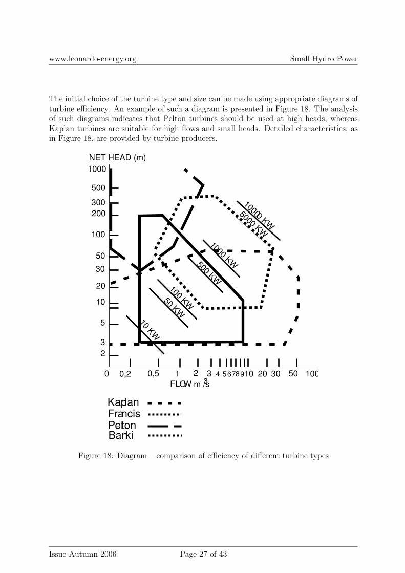
The initial choice of the turbine type and size can be made using appropriate diagrams ofturbine efficiency. An example of such a diagram is presented in Figure 18. The analysisof such diagrams indicates that Pelton turbines should be used at high heads, whereasKaplan turbines are suitable for high flows and small heads. Detailed characteristics, asin Figure 18, are provided by turbine producers.
Kaplan FrancisPeltonBanki
1000
500
300
200
100
50
30
20
10
5
3
2
0 0,2 0,5 1 2 3 4 567 9108 20 30 50 100
10 KW
50 KW
100 KW
500 KW
1000 KW
NET HEAD (m)
5000 KW
10000 KW
FLOW m /s3
Figure 18: Diagram – comparison of efficiency of different turbine types
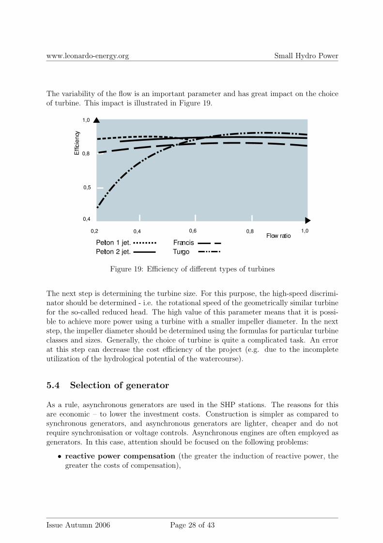
The variability of the flow is an important parameter and has great impact on the choiceof turbine. This impact is illustrated in Figure 19.
0,2 0,4 0,6 0,8 1,0Flow ratio
Effic
iency
0,4
0,5
0,8
1,0
Pelton 1 jet.
Pelton 2 jet. Turgo
Francis
Figure 19: Efficiency of different types of turbines
The next step is determining the turbine size. For this purpose, the high-speed discrimi-nator should be determined - i.e. the rotational speed of the geometrically similar turbinefor the so-called reduced head. The high value of this parameter means that it is possi-ble to achieve more power using a turbine with a smaller impeller diameter. In the nextstep, the impeller diameter should be determined using the formulas for particular turbineclasses and sizes. Generally, the choice of turbine is quite a complicated task. An errorat this step can decrease the cost efficiency of the project (e.g. due to the incompleteutilization of the hydrological potential of the watercourse).
5.4 Selection of generator
As a rule, asynchronous generators are used in the SHP stations. The reasons for thisare economic – to lower the investment costs. Construction is simpler as compared tosynchronous generators, and asynchronous generators are lighter, cheaper and do notrequire synchronisation or voltage controls. Asynchronous engines are often employed asgenerators. In this case, attention should be focused on the following problems:
• reactive power compensation (the greater the induction of reactive power, thegreater the costs of compensation),
• profile of current paths (the necessity of using larger profiles),
• generator loads (operation in lower power range, higher working temperature ofgenerators),
• necessity of rebuilding the power output.
These problems can increase both investment and operational costs.
Three-phase synchronous generators with permanent magnet may also be used in smallhydro power stations. These generators have high efficiency (up to 97%), which is muchhigher than asynchronous generators or direct current generators.
5.5 Automation and protection
Choosing suitable automation and protection systems is one of the major steps in the pro-cess of selecting SHP parameters. The functions to be performed by the automatic controlsystems depend on construction, operational mode (e.g. isolated network operation), andremote control. The primary aim should be to maximise the generation of electric en-ergy. The basic purpose of SHP automation is to ensure safe operation (e.g. emergencyshutdown of the generator and regulation in response to varying water conditions).
More and more investors are realising the need to install modern control systems. BecauseSHP stations are often built in remote areas, investors focus their attention on the remotecontrol systems.
Such a system ensures the continuous optimisation of power generation, without any staffintervention, and thus maximises profit.
Protection of power grid Power grid protection requirements are defined by the ownerof the local network (power distribution company) to which the SHP station is to be con-nected. The SHP protection devices are usually required in their minimum configurationas specified by the network operator, even though the cost share of protection devices inthe total investment costs is small. The growing requirements regarding grid security andconnected customer equipment are contributing to the installation of more modern andreliable protection systems.
Project documentation should contain the rationale of the investment and its profitability.The positive balance of costs and returns, as well as good return on investment, is thebasis for obtaining the necessary investment funds and bank loans.
P R O J E C T
INCOMES
INVESTMENTS
EXPLOITATION OTHER EXPLOITATION
PRODUCTION
COSTS
Figure 20: Project preparation: analysis of costs and revenues
Methodology and procedures For chosen pipe profiles, passages, sluices and canals,the water flows should be determined according to the following procedure:
• estimate the depth and speed of the water flow in the canal,
• determine the heights of the flow control structures - e.g. dams, weirs, places ofpotential overflows,
• analyse return flows and the impact of dams on such flows,
• establish the height and width of transport canals,
• determine whether the flow is sub-critical or super-critical (this allows the level offlow stability and irregularity to be predicted),
• determine the slope of the canal to minimise turbulences,
• establish optimal canal parameters from the point of view of cost (i.e. determinethe best dimensions for maintaining the required level of flow),
• calculate the required smoothness of the canal; reduce costs by using suitable ma-terial for canal formwork, which should assure maximum depths,
• determine the minimum size of the pipe in order to avoid increased pressure flows,
• compare different shapes without changing the intake levels.
The documentation of the project and its implementation should be prepared and carriedout according to applicable standards and requirements.
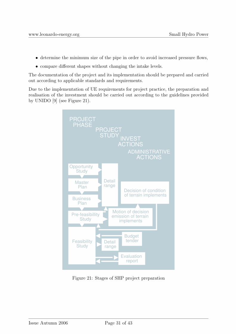
Due to the implementation of UE requirements for project practice, the preparation andrealisation of the investment should be carried out according to the guidelines providedby UNIDO [9] (see Figure 21).
The RES Directive of the European Parliament provides general requirements concerningadministrative actions for the promotion of energy from renewable sources. The provi-sions of this Directive oblige administrative bodies to reduce all barriers limiting energyproduction from renewable sources.1
The rules of SHP investment preparation are similar in almost all of the EU countrieswhere licenses concerning land use and environment are required. In general, specialisedagencies and local communities need to be consulted regarding the way environmentalresources are to be used, especially in the case of large projects. Official permissions areknown as licences. The content of these documents is defined by applicable laws (e.g.the Water Law). The superior regulations are defined in the so-called Water Directive(WFD)2 of the European Parliament. In Norway, where almost all energy is producedfrom hydro power stations, licences are issued pursuant to the Water Regulation Act andEnergy Act. The procedure for obtaining a licence is quite long and complicated, and isoverseen at many stages. For SHP projects, the duration of this procedure ranges from1 to 5 years (2-3 years on average)3. This process also needs to be approved by the localcommunities. A project may have to be changed (e.g. its scope may have to be limited)before the licence is finally issued by the proper authorities (MPE).
In Greece, obtaining appropriate licences also requires community consultations and isquite complicated. Licences are authorised by the Ministry of Development followingtheir acceptance by the energy commission - RAE (Regularity Authority for Energy).The procedure usually lasts from 6 to 12 months.
In Austria, where the energy market is fully open 4, licences are issued by the provincialauthorities, but for SHP schemes up to 500kW, such licences are not required.5.However,the local distribution company is not obliged to purchase SHP energy, and the sale ofenergy is done using market prices.
In Switzerland, the certification of SHP projects is in accordance with green hydrostandards, where SHP projects have to meet the environmental standards. For SHPschemes, the procedures for acquiring licences and certifications are simplified - someSHP types do not require licences.
1 DIRECTIVE 2001/77/EC of 27 September 2001 on the promotion of electricity produced fromrenewable energy sources in the internal electricity market
2 DIRECTIVE 2000/60/EC of 23 October 2000 establishing a framework for Community action inthe field of water policy
3 The Licensing Procedures for Hydropower Development in Norway, http://www.nve.no4 The Energy Liberalization Act – ”Energieliberalisierungsgesetz” (BGBl I 2000/121; in the following
”ELG”)5 The Transposition of Directive 96/62/EC on the Internal Market in Electricity into Austrian Law,
• Abstraction Licence, for hydro power stations with derivation canals,
• Impoundment Licence, for all hydro-technical structures affecting water rela-tions,
• Water and Drainage Consent, if any works are to be carried out in the mainchannel,
Section 158 Agreement contains certain further requirements [12].
In Poland, the use of water resources is regulated by the ’Water Law’ [7], which sets outthe obligations of administrative bodies with respect to water management. These bodiesissue required water-law permits, which define the aim and range of water utilisation andfurther environmental, social and economic requirements. The application for a water-lawpermit is submitted with an additional document called the ’Water-Law Survey’, whichcontains:
• characteristics of the waters covered by the water-law permit,
• determination of impact of water utilisation on the surface and underground waters,
• procedures to be carried out in certain operational cases, accidents, etc.,
• layout of water equipment and functional diagram.
Financing sources Financing of SHP projects is incorporated in the mechanisms ofthe support and financing of RES. Evidence of RES support are the applicable EU Di-rectives and resulting national development plans. Financial support of RES comes fromboth private and public sources. The range of finance fluctuates from macro- to micro-scale, depending on project size, as in the case of home-based and micro hydro stations.Recently, more and more banks are interested in financing RES projects, as this is seenas a good business opportunity. A significant role is played by bank institutions, with theEuropean Investment Bank and the European Bank for Reconstruction and Development(EBRD) as examples of such institutions in the EU. Financial support also comes fromdifferent kinds of organisations and government agencies, e.g. the German DevelopmentFinance Group (KfW). In 2004, the KfW managed about 180 million euro for RES devel-opment. In this case, the German government allots about 500 million euro to the KfWfor RES support in the developing countries. In the case of smaller investments, somefinancial support for RES can be expected from various non-government organisations(e.g. industrial networks, private foundations). A good example is the Renewable EnergyPolicy Network (RENv21). There are also other financial instruments of great importancesuch as grants, subsidies, preferences, facilities and taxes. These instruments may dependon local or regional conditions.
In Poland, one of the major financing sources for RES, including SHP, is the NationalFund for Environment Protection and Water Management. The Bank of EnvironmentalProtection grants preferential loans for investment in the area of environmental protection.
The major channels of SHP support include the so-called Norway Financial Mechanismand the European Industry Area Financial Mechanism. These sources of finance areadditional to the EU Structural Funds, which benefit the new EU countries. Norway,Iceland and Liechtenstein (EFTA) are the donors.
Conditions of financing When creating a financial plan for SHP, the following shouldbe taken into consideration:
• large costs of hydro-technical infrastructure,
• project lifetime of SHP is longer than period of capital return.
In the case of SHP, a major cost component can be the preparation of project documen-tation and the feasibility study - this can even amount to 50% of the costs. In the project,inexpensive and typical solutions should be applied. The contractor may have a substan-tial cost impact, so this must be fully authorised. The investment loans of 60-80% of theproject value may be granted, and they come mainly from government institutions. The
projects are often co-financed by local institutions, industry, and financial institutionsinterested in long-term financing.
Most investors do not have sufficient resources for project investment. Due to the highrisk of investment, the cost of acquired capital can be expensive. It may be obtainedfrom several sources, which can also increase the costs. Because this is regarded as ahigh risk investment, banks may require additional guarantees or special supervision ofthe development process. In some cases, a consumer loan is also possible. The period ofcapital return on investment is estimated to be 10 to 20 years, and up to 10 years in thecase of commercial banks. The key to success is a properly prepared project, includingan accurate estimation of future revenues.
8 Economy
Cost of investment The costs of an SHP project depend on:
• type of SHP (run of river, reservoir),
• installed power and number of hydro-generators,
• useable head,
• capacity of water reservoir,
• local circumstances (terrain configuration, length and height of any basin embank-ment, hydrological conditions, costs of land use, etc.).
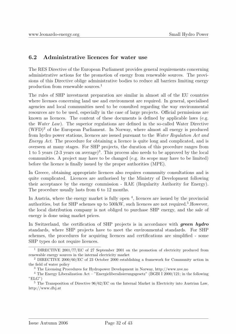
Unit investment costs for SHP are illustrated in Figure 22.
Figure 22: Unit investment costs of SHP (for head of H=10m)
A general SHP project cost level is very difficult to present, because projects are neitheruniform nor comparable. Depending on the local environmental conditions, differentsolutions are used for different locations, hydro-technical constructions, turbines, andelectrical equipment.
The percentage contribution of the main costs to the total cost of investment is shown infigure 23:
HYDROTECHNICALCONSTRUCTION
TURBINES
BUILDINGS
ELECTRICAL EQUIPMENT
COSTS OF EXPLOITATION
Elements of investment Participation Up to %
60
25
5
100,50
Figure 23: Investment cost breakdown
SHP Business Plan A simplified version of the business plan for an SHP project ispresented in [8]. This plan refers to the construction of a basic hydro power station with
basic automation. It was assumed that the construction of the powerhouse and the turbineinstallation will be very cheap, and future energy prices will not drop below the presentprices.
Equipment and parameters
Lever turbine without control of impeller blades. Three blades ∅1000 mm in diameter.
Power on the clamps of generator 32KW
Fixed water gullet (turbine flow) 2.5m3/s
Turbine rotational speed 238 rpm.
Transmission belt.
Simplified cost calculations (based on Polish prices) :
For construction purposes, it is proposed to borrow G-4 larsen whetstone (40m of wall tothe depth of 4 m). Costs about e6 500.
General costs:
Materials e7 200Labour e7 200Turbine + belt gear e37,500Automation for turbine e1 250Bars on the inlet e1 250Generator e1 500Total construction costs e55,900 (gross)
The VAT tax is recoverable from the above total. The total net cost of an SHP projectwill usually be less than e50 000.
The balance of costs and revenues should be related to the local water circumstances.To estimate revenues, the energy price of PLN 0.09 c/kWh may be assumed. When theturbine efficiency is assumed to be 70%, the revenues will be:
8640 · 0.7 · 32 · 0.09 ≈ 17500e/year (6)
In such a case, the payback period is about 3 years.
A business plan of the full project with a Kaplan turbine and a generator of a similar sizeis presented in [13]. The total project cost was approximately $ 200 000 - i.e. $ 2 097/per kW installed power. These are obviously quite different cost levels. The costlevel of 1 000-2 000 e/kW is typical.
9 Environment
As a rule of thumb, water management is conducted according to communityinterests and to avoid environmental pollution.
Fish protection Fish protection is one of the major problems faced by SHP investors.SHP stations must be equipped with the hydro-technical equipment designed for thesepurposes. Such equipment includes the following:
• fish-passes, fish ladders/lifts,
• by-pass canals,
• screen plates, cover bars.
Fish-passes can vary in construction.
They are often built in the form of multi chamber, cascade canals. The canal withchambers covers the entire head, from high to low water level, and may be used to limitthe water speed in the case of fast flow. Such a solution is presented in Figure 24.
The most often used and efficient way of fish protection from the upstream level arescreen plates made of steel bars with a clearance of 1-1.5 cm. These screens have to be ofadequate size and should be mounted far away from the turbine inlet.
The recommended speed of the water near the bars should be at the level of 0.30-0.40m/s.The fixed bar screens should stop the fish and direct them to the opposite river bank oronto the surface. Apart from the fixed screens, screens in the shape of rotated net gatesare also mounted.
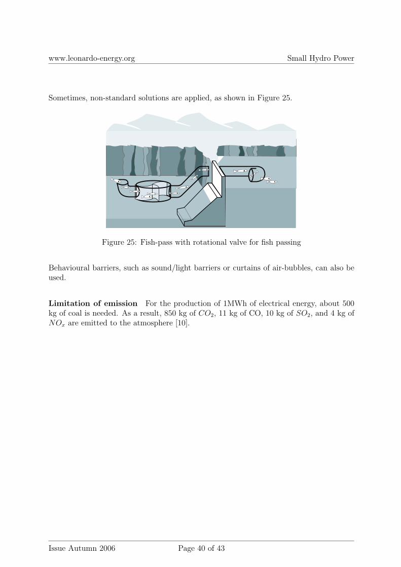
Sometimes, non-standard solutions are applied, as shown in Figure 25.
Figure 25: Fish-pass with rotational valve for fish passing
Behavioural barriers, such as sound/light barriers or curtains of air-bubbles, can also beused.
Limitation of emission For the production of 1MWh of electrical energy, about 500kg of coal is needed. As a result, 850 kg of CO2, 11 kg of CO, 10 kg of SO2, and 4 kg ofNOx are emitted to the atmosphere [10].
There are some associations and specialty organisations that can provide help and con-sultation to SHP investors at the stage of project preparation and realisation. The EUleading organisation is the European Small Hydropower Association (ESHA) [11]. TheESHA is the platform for information exchange on the European scale. In the countriesin which SHPs are built, national organisations have been established (e.g. the BritishHydropower Association (BHA) in the UK). Scientific and research organisations are alsoavailable.
11 Summary – essential requirements and threats
Initial stage (before realisation)Question: What to do? Remarks
• determine expectations con-cerning SHP:
• financial,• with regard to realisation,• with regard to operations,• become familiar with:• electrical energy trade condi-
’the myth of flowing water’ which is only thesource of revenues should be opposed to solid anal-ysis of expectations, which should be fulfilled ateach stage of project implementation
choice of types and number of turbines de-pending on the flow should guarantee the full useof the energy potential of the site and optimiseelectrical energy production
prepare business plan, feasibilitystudy, financial security of invest-ment
correct determination of costs for each part ofthe project enables the planned technical level ofSHP to be reached
realisation of investment before starting the project, it is advisable toconsult a broad group of specialists in each area,while taking into account high investment costs
technical acceptance, putting intooperation
it is essential to fulfil the requirements concern-ing security of operations, grid protection, me-tering and settlement system, protection againstflooding,
contract on sale and receipt of elec-trical energy
market analysis, contract preparation, fulfil-ment of energy trade requirements
operations requirements:• formal and legal, concerning trade of energy,• technical, connected with operations and en-
vironment,• financial, connected with operating costs,
[1] Communication from the Commission ENERGY FOR THE FUTURE: RENEW-ABLE SOURCES OF ENERGY, White Paper for a Community Strategy and ActionPlan, COM(97) 599 final (26/11/1997).
[2] Small hydropower – A proven technology for a clean and sustainable energy future ,http://www.erec-renewables.org/
[3] ESHA, www.esha.be/BlueAge.pdf
[4] Laymans guidebook – how to develop a small hydro site, www.esha.com.
[5] J. Terrien and other, Fish passage at small hydro sites, IEA Technical Report. March2000.
[6] ydanowicz J., Namiotkiewicz M., Kowalewski B., Zabezpieczenia i automatyka wenergetyce, WNT, Warsaw 1985.
[7] Nowelizacja Ustawy ,,Prawo wodne’, Dz.U. z 2005 r. Nr 130, poz. 1087.


![Electrical Power Quality and Utilisation, Journal Vol. …2].pdf7 Electrical Power Quality and Utilisation, Journal Vol. XV, No. 2, 2009 Power Quality and EMC in Smart Grid Magnus](https://static.documents.pub/doc/80x56/5ae959477f8b9aee0790b36c/electrical-power-quality-and-utilisation-journal-vol-2pdf7-electrical-power.jpg)
![Electrical Power Quality and Utilisation, Journal Vol. …2].pdf47 Electrical Power Quality and Utilisation, Journal Vol. XV, No. 2, 2009 Estimation of Optimum Value of Y-Capacitor](https://static.documents.pub/doc/80x56/5ae959477f8b9aee0790b35d/electrical-power-quality-and-utilisation-journal-vol-2pdf47-electrical-power.jpg)


