33
Power Quality Case Studies: Power Quality Case Studies: Voltage Sag/Voltage Drop Music City Power Quality Group Meeting November 28 th , 2012 Ed M Sti tt PE CEM Ed M. Stinnett, P .E., CEM

Power Quality Case Studies:Power Quality Case Studies:Voltage Sag/Voltage Drop
Music City Power Quality Group MeetingNovember 28th, 2012
Ed M Sti tt P E CEMEd M. Stinnett, P.E., CEM

Objecti esObjecti es Case St d #1Case St d #1ObjectivesObjectives--Case Study #1Case Study #1Describe the thought process behind solving a power quality issueDescribe the thought process behind solving a power quality issue
while analyzing data in the order we received it.
Discuss what to look for when control circuits are a possible causeDiscuss what to look for when control circuits are a possible cause
of power quality problems.
Discuss ESTOP circuits with ice cube relaysDiscuss ESTOP circuits with ice cube relays.
Identify whether a relay is AC or DC from an elementary diagram
of a control circuitof a control circuit.

Problem #1Problem #1 –– Voltage SagVoltage SagProblem #1 Problem #1 Voltage SagVoltage SagA large industrial customer has two “identical” processA large industrial customer has two identical process lines adjacent to each other in a manufacturing facility. The first process line (Good Line) is fed from a 1500kVA, 480Y/277V transformer and never has any i iissues where equipment drops out or loses power.The second process line (Bad Line) is fed from a second 1500kVA, 480Y/277V “identical” transformer. Th B d Li l lThe Bad Line constantly loses power.“Losing power” is defined as the dropping out of the controls and motors involved with the second process liline. Power loss causes the customer thousands of dollars of lost production each time it happens.

Initial Thoughts on Causes of the Initial Thoughts on Causes of the PQ Issues:PQ Issues:
The problem must be because the utility transformer isThe problem must be because the utility transformer is defective.
• The Bad Line transformer was replaced less than a year agoyear ago.
• If the “identical” Good Line works fine with a duplicate transformer, the point of failure has to be the Bad Line transformer.
There are issues with the incoming medium voltage feeder to the transformer in question.feeder to the transformer in question.
• Bad arrestor?• Tree trimming issues causing voltage sags?

Single Line Diagram of SystemSingle Line Diagram of SystemSingle Line Diagram of SystemSingle Line Diagram of System

Step 1: Meter Incoming UtilityStep 1: Meter Incoming Utility(Good Line)(Good Line)(Good Line)(Good Line)
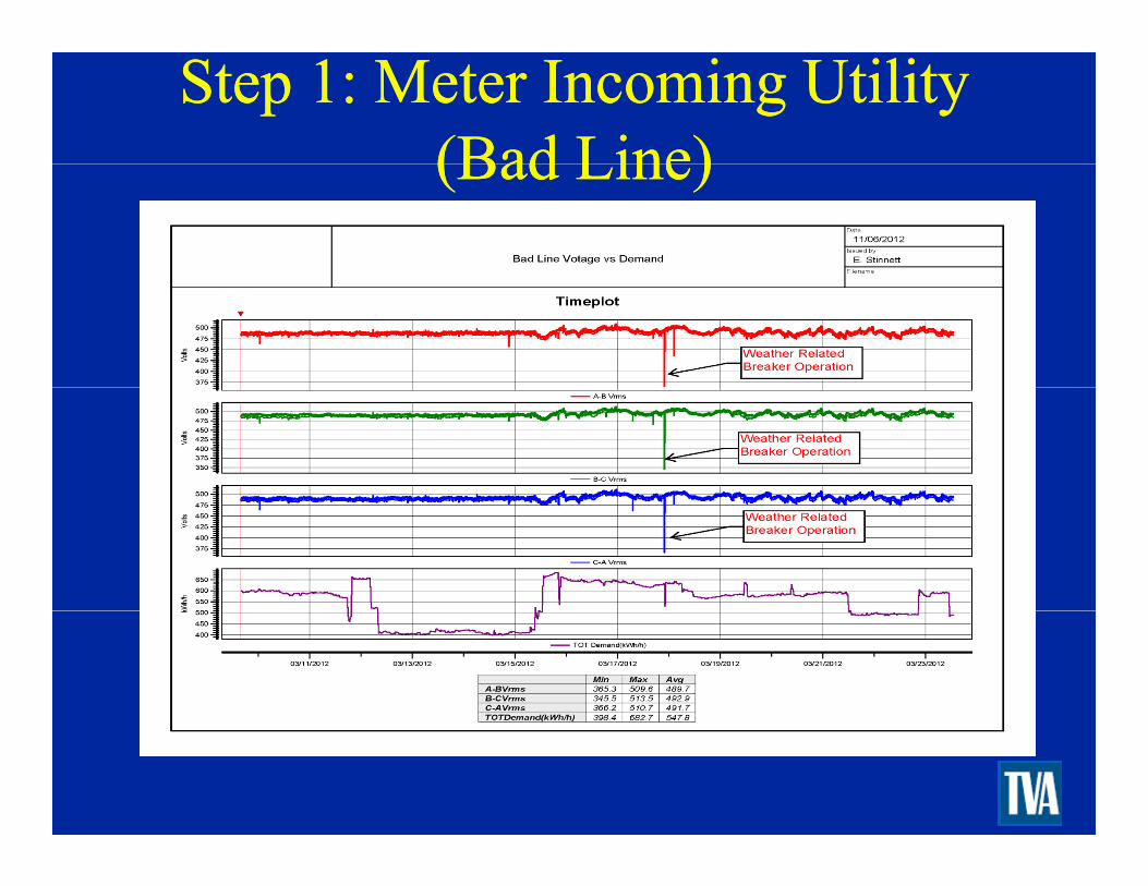
Step 1: Meter Incoming UtilityStep 1: Meter Incoming Utility(Bad Line)(Bad Line)(Bad Line)(Bad Line)

Conclusions Post MeteringConclusions Post MeteringWe can most likely rule out utility line issues because both transformers are fed from the same utilityboth transformers are fed from the same utility feeder. A sag on the line is seen by both transformers.The Bad Line transformer seems to maintain a
t t 480V lt d i th it i i dconstant 480V voltage during the monitoring period. Voltage sags measured at the Bad Line were identical to those on the Good Line.Maybe both process lines are not identical. Solution to their problems might be traced to a point where both lines are different.Time to go into the plant a look at the layout of the two lines.

Interior Layout of Both LinesInterior Layout of Both LinesBoth lines are fed from separate switchboards.B th li j it l d (M t l d )Both lines are majority conveyor loads (Motor loads) with some process loads to manufacture and move product.The control systems of both lines are separate and are comprised of several large PLC cabinets coupled with motor control cabinets.
• These motor control cabinets house the overcurrent protection and contactors necessary to turn motors on and off.turn motors on and off.

Interior Layout of both LinesInterior Layout of both LinesThe first difference between the two lines is noted:
Th G d Li t b l f• The Good Line must be a couple of years newer than the Bad Line. How do I know this?
- The Good Line is using Allen Bradley ControlLogix PLCs.
- The Bad Line is using Allen Bradley SLC 500 PLCs.PLCs.

New Information from Actual New Information from Actual Operator of the Bad LineOperator of the Bad LineOperator of the Bad LineOperator of the Bad Line
When an outage occurs, the PLC and remote IO racks do not necessarily lose power.do not necessarily lose power.
• Control screen is running when the operator shows up to restart the line.
All of the motor loads do lose power or drop out.• This causes the operator to have to press an
acknowledge button on his control screen.acknowledge button on his control screen.• Once the acknowledge has been pushed, the
operator can then restart all of the motors to put the s stem back onlinethe system back online.
• Something must be dropping out the master control relays (MCR) within the motor panel.

And the Weak Link Is…And the Weak Link Is…Emergency Stop (ESTOP) buttons or pull cords are circuits designed to shutdown lines or sections of linescircuits designed to shutdown lines or sections of lines anytime there is an emergency.
• A relay within an ESTOP circuit is wired back to MCR ithi t l B i b ttMCRs within motor panels. By pressing a button (usually a big red one) or by pulling a pull-cord, the hardwired circuit is broken and an ESTOP rela coil is de energi edrelay coil is de-energized.
• Once the ESTOP coil is de-energized the MCR within a motor panel drops out and all of the motors on that circuit shut down instantly to prevent injury or damage to equipment.

RelaysRelaysRelaysRelays

The SolutionThe SolutionA comparison of ESTOP circuitry between the Good Line and the Bad Line showed that the Good Line wasLine and the Bad Line showed that the Good Line was utilizing DC relays while the Bad Line was using AC relays for their ESTOP circuits.Th AC E St l f th B d LiThe AC E-Stop relays from the Bad Line were replaced with DC relays a month after study was done. Process outages due to momentary voltage sags have ceased even during summer storm months.

What does an ESTOP circuit look What does an ESTOP circuit look like?like?like?like?

What does an ESTOP circuit look What does an ESTOP circuit look like?like?like?like?

Where do you find the relays?Where do you find the relays?

ConclusionsConclusions
Be weary of “identical” systems.Be weary of “identical” systems.Be weary of identical systems.Be weary of identical systems.When groups of motors drop offline at the same time, When groups of motors drop offline at the same time, try to identify whether they are controlled by a single try to identify whether they are controlled by a single Mater Control RelayMater Control RelayMater Control Relay.Mater Control Relay.Master Control Relays are usually designed to drop Master Control Relays are usually designed to drop out when Eout when E--Stop circuits lose power.Stop circuits lose power.Obtain Elementary or Riser diagrams when possible to Obtain Elementary or Riser diagrams when possible to trace controls circuits and locate AC relays.trace controls circuits and locate AC relays.

Questions?Questions?Questions?Questions?

Objecti esObjecti es Case St d #2Case St d #2ObjectivesObjectives--Case Study #2Case Study #2Present an obvious voltage drop issue feeding a motor withPresent an obvious voltage drop issue feeding a motor with
undersized wire.
Look at the metered voltage and current data at both the motorLook at the metered voltage and current data at both the motor
terminals and the panel feeding the motor.
Discuss NEC requirements for overload protectionDiscuss NEC requirements for overload protection.
Discuss NEC requirements for cable sizing.
Discuss possible options other than resizing cable.

Problem #2Problem #2 –– Voltage DropVoltage DropProblem #2 Problem #2 Voltage DropVoltage DropA small commercial customer owns a property that hasA small commercial customer owns a property that has several automatic gates.All of the gates work fine except for one that constantly trips its internal overload device.trips its internal overload device.All of the circuits/gates/parts are identical (Awesome…Another “identical” system).All of the components of the gate have been changedAll of the components of the gate have been changed out and replaced (motors, gears, breaker, etc) except for the feeder to the motor.Motor is a 1/2hp 120V with integral overloadMotor is a 1/2hp, 120V, with integral overload protection. Motor is fed by 550 ft of 2#8, #10G-1/2”C

Initial Thoughts on Causes of the Initial Thoughts on Causes of the PQ Issues:PQ Issues:
Motor/gate assembly is mechanically failingMotor/gate assembly is mechanically failing• Mechanical impedance of the motor shaft is
increasing current drawOverloads are undersizedSpikes from the utility are causing the overloads to tripVoltage Drop issuesVoltage Drop issues
Diagram of SystemDiagram of SystemDiagram of SystemDiagram of System

Metered Data at PanelMetered Data at PanelMetered Data at PanelMetered Data at Panel

Voltage at Motor TerminalsVoltage at Motor TerminalsVoltage at Motor TerminalsVoltage at Motor Terminals
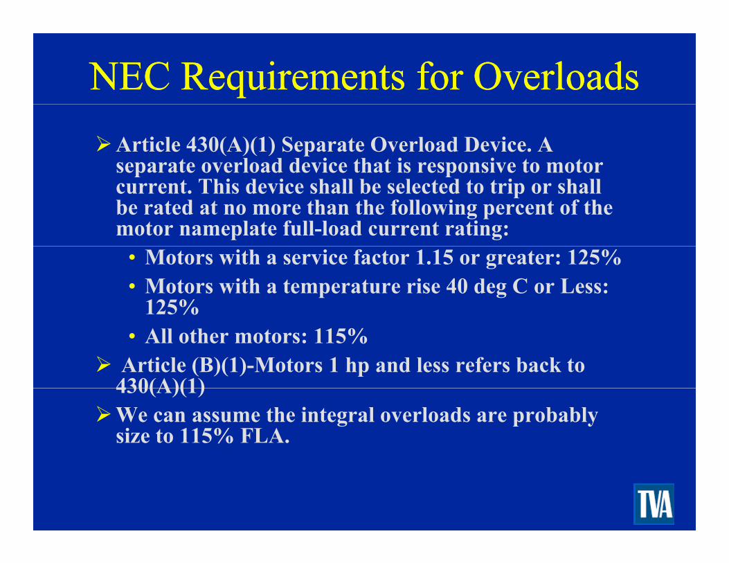
NEC Requirements for OverloadsNEC Requirements for OverloadsArticle 430(A)(1) Separate Overload Device. A separate overload device that is responsive to motor p pcurrent. This device shall be selected to trip or shall be rated at no more than the following percent of the motor nameplate full-load current rating:
• Motors with a service factor 1.15 or greater: 125%• Motors with a temperature rise 40 deg C or Less:
125%• All other motors: 115%
Article (B)(1)-Motors 1 hp and less refers back to 430(A)(1)430(A)(1)We can assume the integral overloads are probably size to 115% FLA.

Overloads (Cont.)Overloads (Cont.)Using motor full load values from NEC table 430.250, we can estimate what current trips the overloadwe can estimate what current trips the overload assuming it’s sized at 115%:
• FLA=9.8A at 115V• 9.8A x 1.15% = 11.27A
Our metered data explains why the overload works sometimes and trips at others.sometimes and trips at others.

Metered Data at PanelMetered Data at PanelMetered Data at PanelMetered Data at Panel

NEC Voltage Drop NEC Voltage Drop RecommendationsRecommendationsRecommendationsRecommendations
NEC recommends no more than 3% voltage drop for either feeder circuits or branch circuits where theeither feeder circuits or branch circuits where the maximum total voltage drop on both feeders and branch circuits to the furthest device does not exceed 5%5%Voltage Drop Calculation for our circuit to the motor:
• Vdrop = (2xLengthxResistancexI)/1000• Vdrop = (2x550ftx0.778x9.8A)/1000 = 8.39V• 8.39V/120V = 6.9% VD

What is the correct size?What is the correct size?After substituting in the resistance values (Chapter 9, Table 8 in the NEC) for larger cables, we find that #4Table 8 in the NEC) for larger cables, we find that #4 AWG reduces the voltage drop to acceptable levels.Voltage Drop Calculation for our circuit to the motor:
• Vdrop = (2xLengthxResistancexI)/1000• Vdrop = (2x550ftx0.308x9.8A)/1000 = 3.32V
3 32V/120V 2 76% VD• 3.32V/120V = 2.76% VD
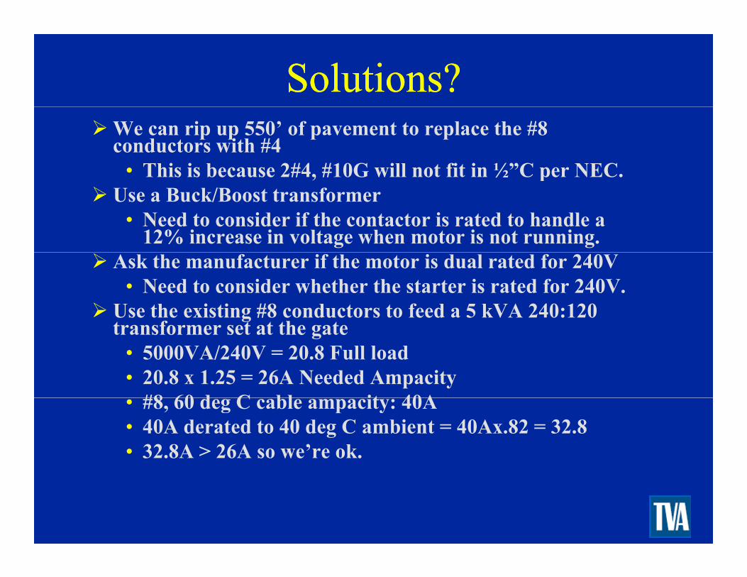
Solutions?Solutions?We can rip up 550’ of pavement to replace the #8 conductors with #4
• This is because 2#4, #10G will not fit in ½”C per NEC., pUse a Buck/Boost transformer
• Need to consider if the contactor is rated to handle a 12% increase in voltage when motor is not running.
Ask the manufacturer if the motor is dual rated for 240V• Need to consider whether the starter is rated for 240V.
Use the existing #8 conductors to feed a 5 kVA 240:120 transformer set at the gatetransformer set at the gate
• 5000VA/240V = 20.8 Full load• 20.8 x 1.25 = 26A Needed Ampacity
#8 60 d C bl it 40A• #8, 60 deg C cable ampacity: 40A• 40A derated to 40 deg C ambient = 40Ax.82 = 32.8 • 32.8A > 26A so we’re ok.

Solutions (Cont.)Solutions (Cont.)New voltage drop calculation with 240V single phase transformer:transformer:
• Vdrop = (2xLengthxResistancexI)/1000• Vdrop = (2x550ftx0.778x4.9A)/1000 = 4.19V• 4.18V/240V = 1.7% VD
Other Considerations:• Make sure there is space for a 2 pole breaker in the
panel• Cost of pulling up cable versus cost of outdoorCost of pulling up cable versus cost of outdoor
rated dry type transformer

Questions?Questions?Questions?Questions?


