68
Power Quality Design Issues for AC Drives Keith Benson IEEE- MCPQ 2/1/2005
Power Quality Design Issuesfor
AC Drives
Keith BensonIEEE- MCPQ2/1/2005

“Power Quality is not a problem for AC Drives unless it is a problem!”
Either
• PQ creates Drive ProblemsOr
• Drive creates PQ problems for
other connected equipment
PQ Issues
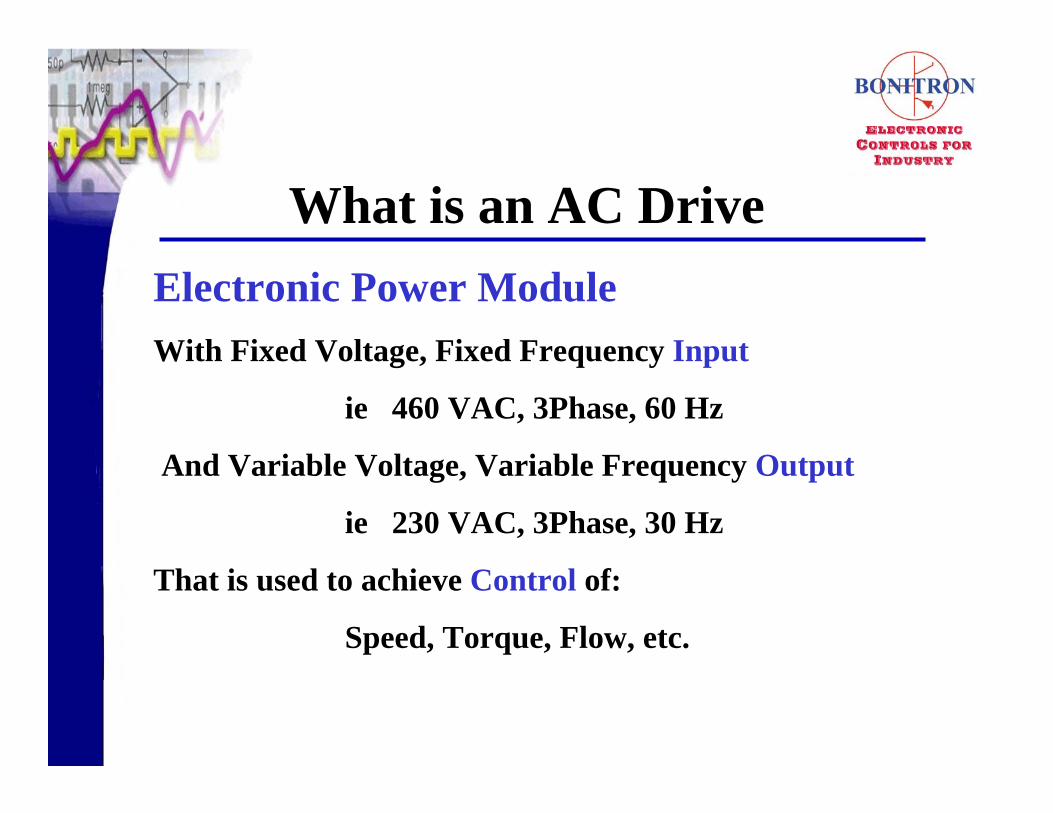
Electronic Power ModuleWith Fixed Voltage, Fixed Frequency Input
ie 460 VAC, 3Phase, 60 Hz
And Variable Voltage, Variable Frequency Output
ie 230 VAC, 3Phase, 30 Hz
That is used to achieve Control of:
Speed, Torque, Flow, etc.
What is an AC Drive
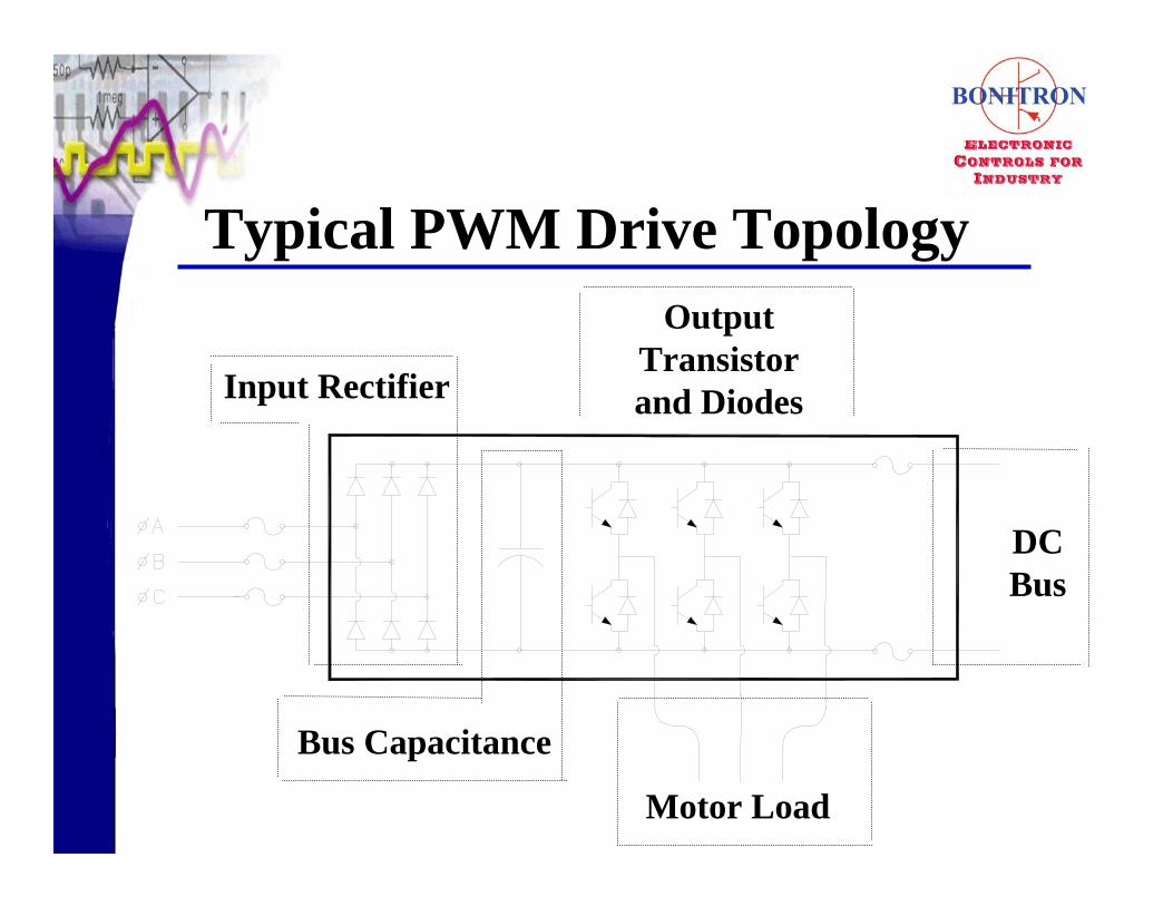
Output Transistor and Diodes
Motor Load
Bus Capacitance
Input Rectifier
DC Bus
Typical PWM Drive Topology

Equal
• Kw
Not Equal
•KVA, Current, Power Factor, Harmonics, etc.
AC Drive Input/Output
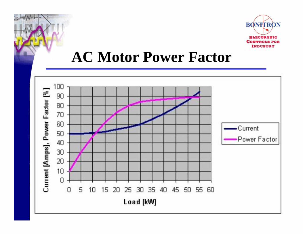
AC Motor Power Factor
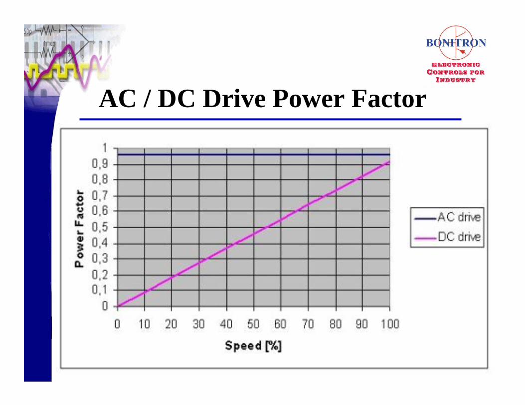
AC / DC Drive Power Factor

• Loss of Drive Enable
• Component Failure
• Over Voltage
• Under Voltage
Drive PQ Problems
What
• Initiates drive shutdown commandWhen
• Loss of 24 VDC I/O supply
• Loss of Interlock Contactor
Loss of Drive Enable

• Fuse
• Capacitor
• Transistor
• Precharge
• MOV
Component PQ Failures

Output Transistor and Diodes
Motor Load
Bus Capacitance
Input Rectifier
DC Bus
Typical PWM Drive Topology

Why
• High RMS CurrentsWhen
• Single Phasing
• Line Unbalance
Fuse PQ Failures
Why
• High Ripple CurrentsWhen
• Single Phasing
• Line Unbalance
Capacitor PQ Failures
Why
• VDC > 2x Nominal
• High Frequency TransientsWhen
• Power factor Capacitor Switching
• SCR Ringing
Transistor PQ Failure Causes
What
• Contacts welding
When
• On Power Dip Recovery
High surge Currents
Precharge Circuit PQ Failures
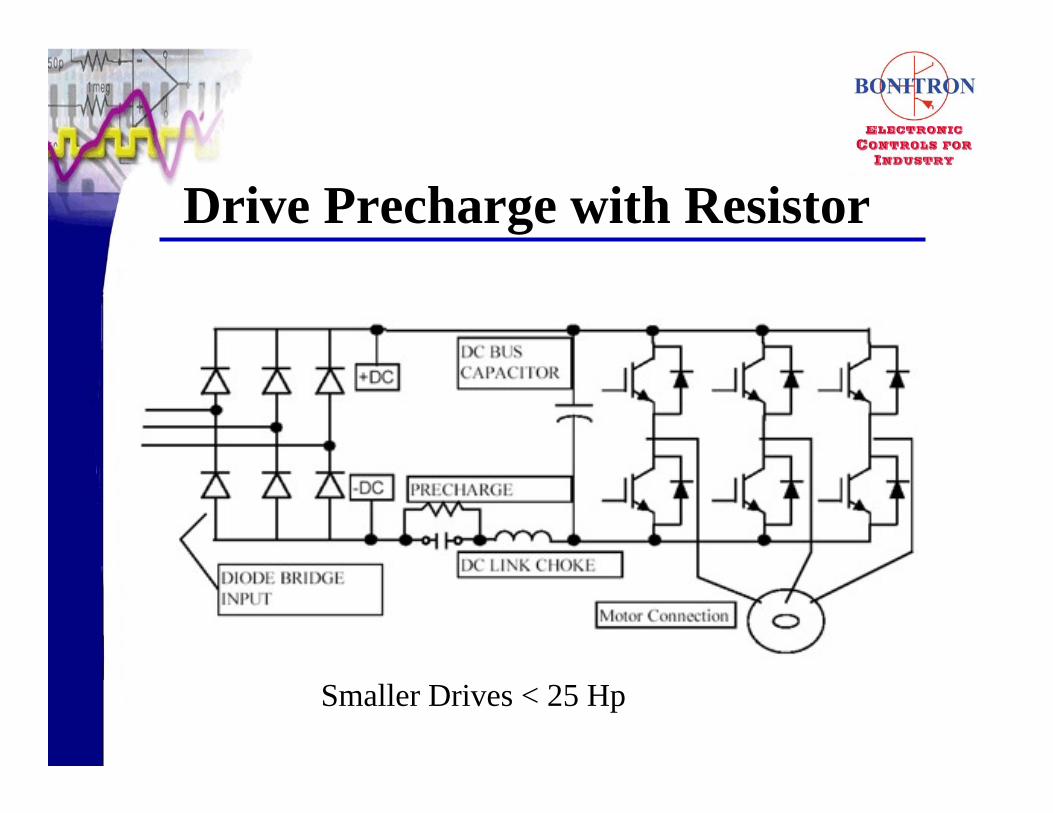
Drive Precharge with Resistor
Smaller Drives < 25 Hp
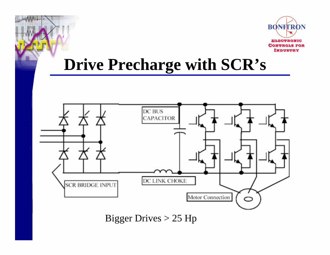
Drive Precharge with SCR’s
Bigger Drives > 25 Hp

Why
• High Peak Over VoltageWhen
• Line Surges and Swells
• Repetitive Transients
• Ring Waves
MOV PQ Failures
Over and Under Voltage Faults
What
• PQ shutdowns are Voltage related,
not Current RelatedHow Sensed
• DC Bus

Output Transistor and Diodes
Motor Load
Bus Capacitance
Input Rectifier
DC Bus
Typical PWM Drive Topology
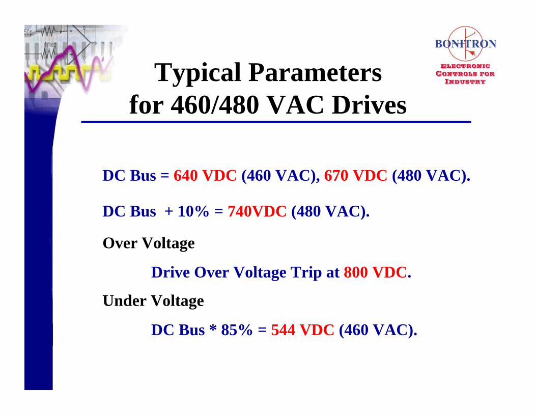
DC Bus = 640 VDC (460 VAC), 670 VDC (480 VAC).
DC Bus + 10% = 740VDC (480 VAC).
Over Voltage
Drive Over Voltage Trip at 800 VDC.
Under Voltage
DC Bus * 85% = 544 VDC (460 VAC).
Typical Parametersfor 460/480 VAC Drives

3 Phase Input
-800
-600
-400
-200
0
200
400
600
800
0 180 360 540 720
A to BB to CC to A
Volta
ge
Degrees
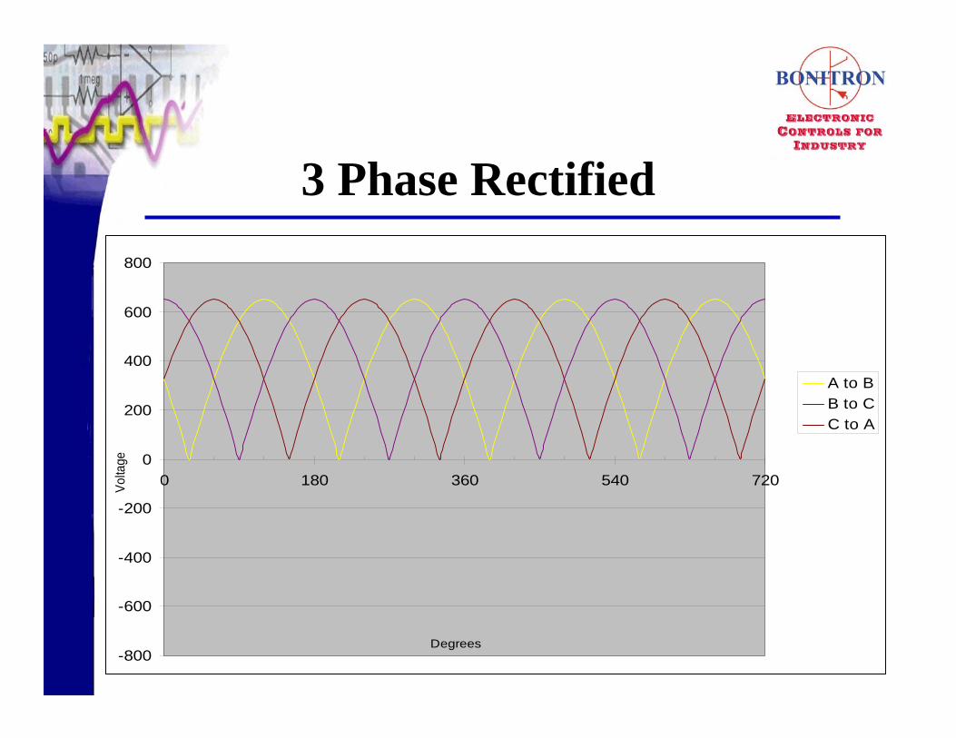
3 Phase Rectified
-800
-600
-400
-200
0
200
400
600
800
0 180 360 540 720
A to BB to CC to A
Volta
ge
Degrees

3 Phase AC, Rectified & DC
-800
-600
-400
-200
0
200
400
600
800
0 180 360 540 720
A to BB to CC to AA to BB to CC to ADC Bus
Volta
ge
Degrees

3 Phase Filtered
-800
-600
-400
-200
0
200
400
600
800
0 180 360 540 720
DC Bus
Volta
ge
Degrees
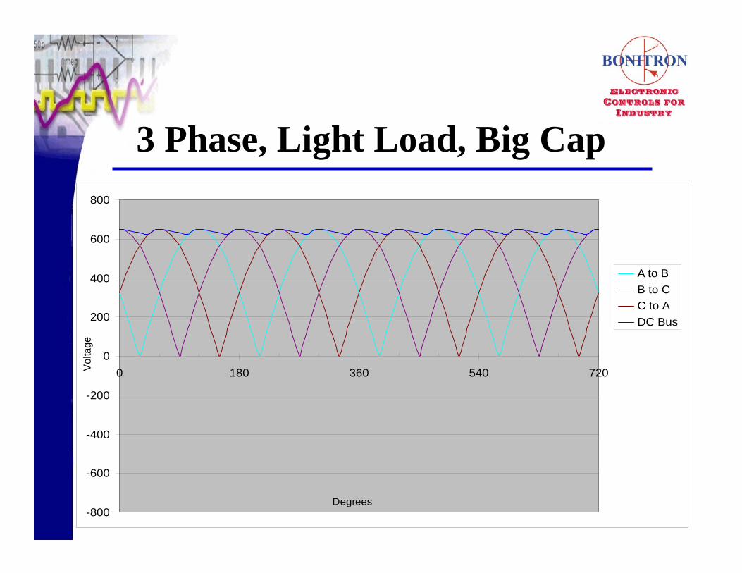
3 Phase, Light Load, Big Cap
-800
-600
-400
-200
0
200
400
600
800
0 180 360 540 720
A to BB to CC to ADC Bus
Volta
ge
Degrees

3 Phase, Heavier Load, small Cap
-800
-600
-400
-200
0
200
400
600
800
0 180 360 540 720
A to BB to CC to ADC Bus
Volta
ge
Degrees
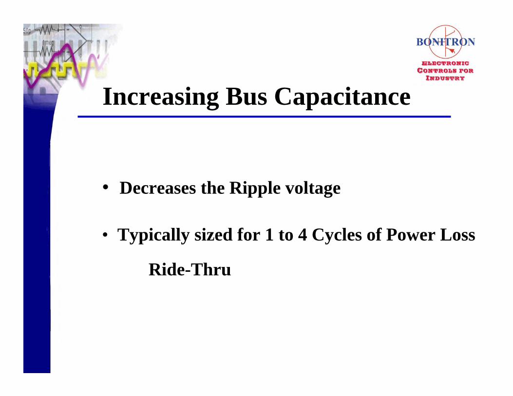
• Decreases the Ripple voltage
• Typically sized for 1 to 4 Cycles of Power Loss
Ride-Thru
Increasing Bus Capacitance

Over and Under Voltage Faults?
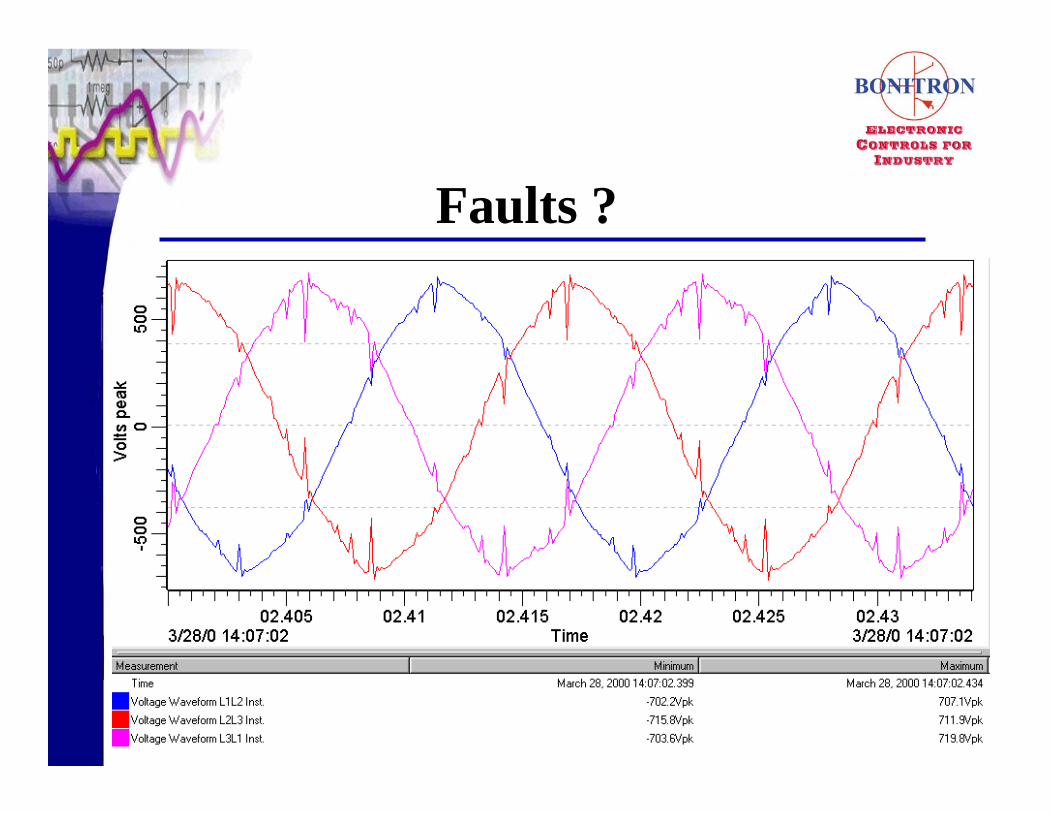
Faults ?
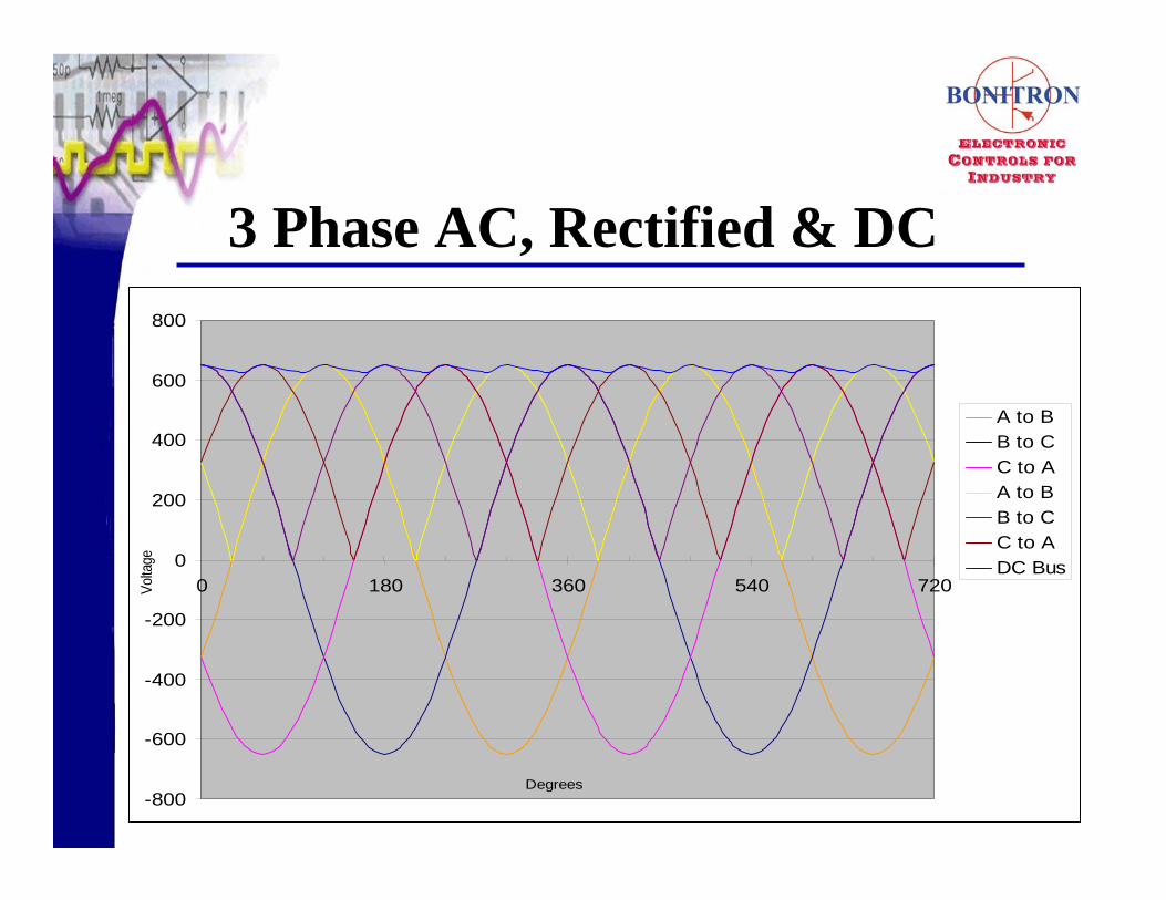
3 Phase AC, Rectified & DC
-800
-600
-400
-200
0
200
400
600
800
0 180 360 540 720
A to BB to CC to AA to BB to CC to ADC Bus
Volta
ge
Degrees
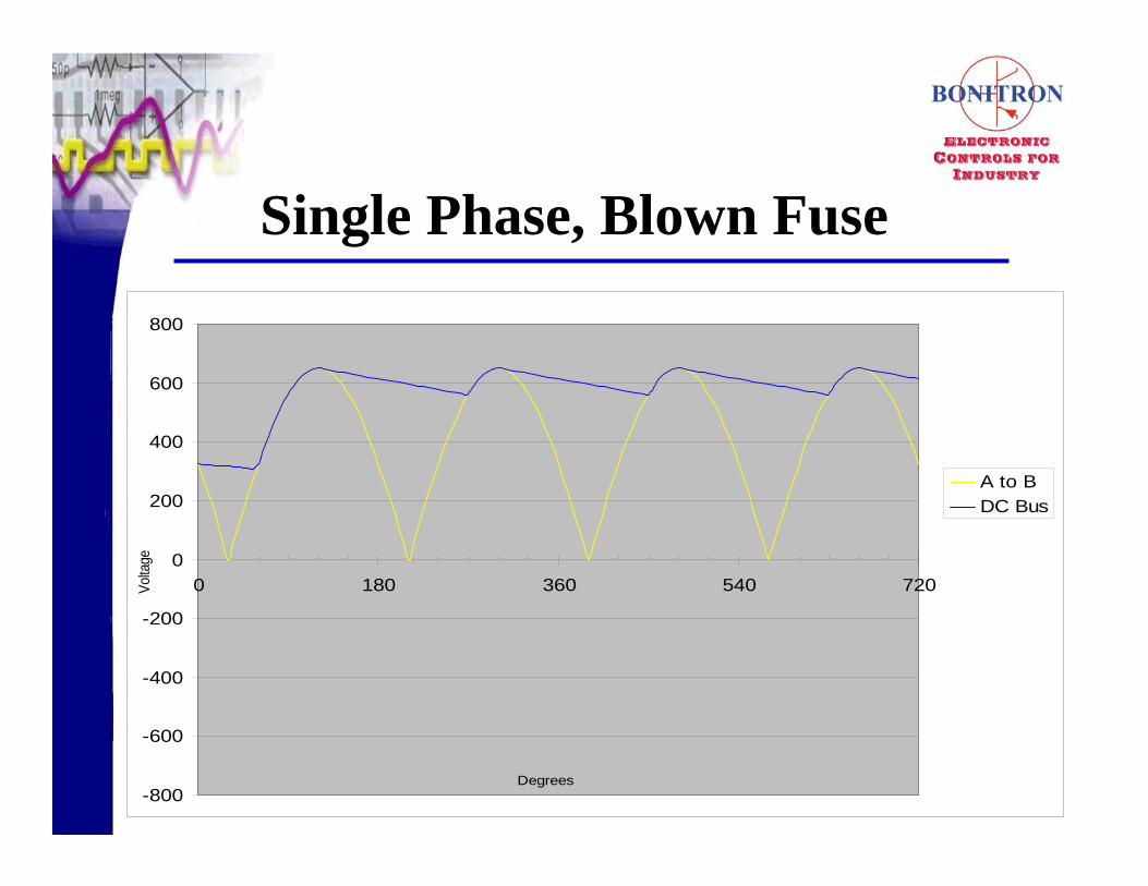
Single Phase, Blown Fuse
-800
-600
-400
-200
0
200
400
600
800
0 180 360 540 720
A to BDC Bus
Volta
ge
Degrees

Over Voltage Faults from LoadWhen
• Motor Braking How
• Parallel Bridge across IGBT’s

Output Transistor and Diodes
Motor Load
Bus Capacitance
Input Rectifier
DC Bus
Typical PWM Drive Topology

AC Drive Input Current
Current Considerations
• Magnitude
• Power Factor
• Distortion / Harmonics
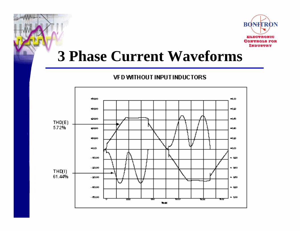
3 Phase Current Waveforms

3 Phase AC, Rectified & DC
-800
-600
-400
-200
0
200
400
600
800
0 180 360 540 720
A to BB to CC to AA to BB to CC to ADC Bus
Volta
ge
Degrees
Decrease Current Distortion
• DC Link Chokes
• Input Line Chokes

Drive Schematic
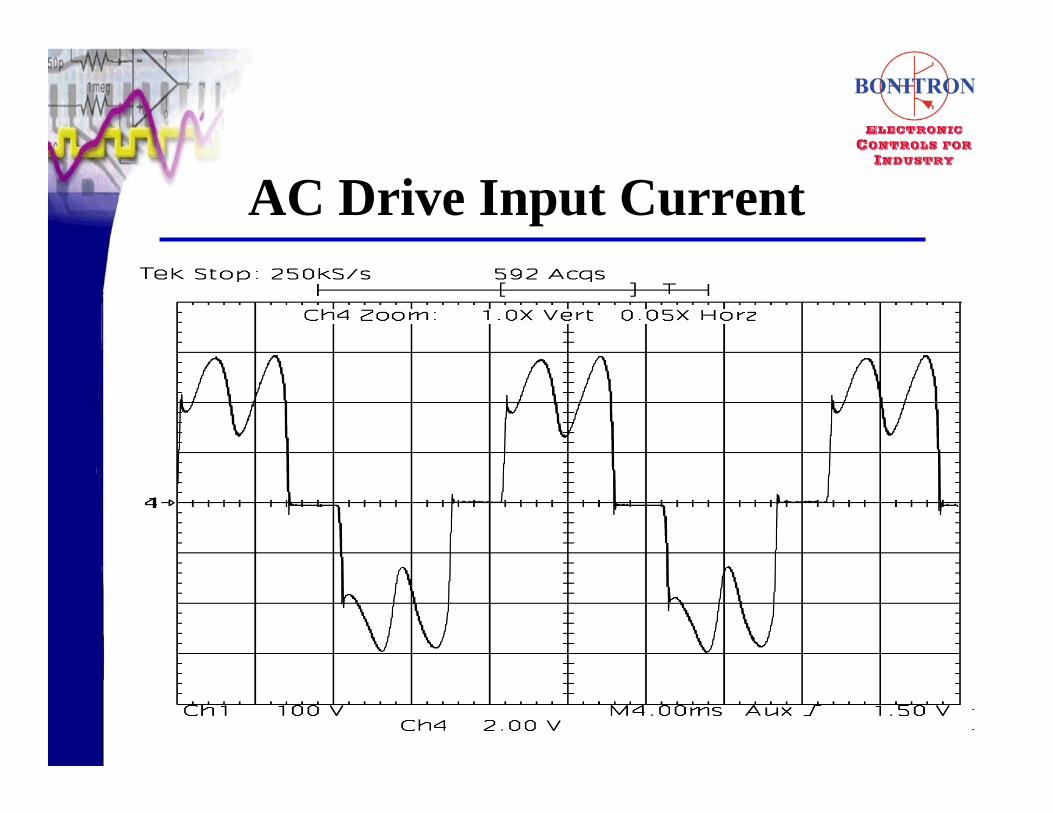
AC Drive Input Current
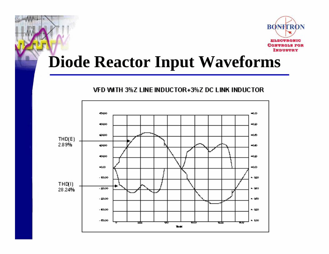
Diode Reactor Input Waveforms

High Z – Flat Topping
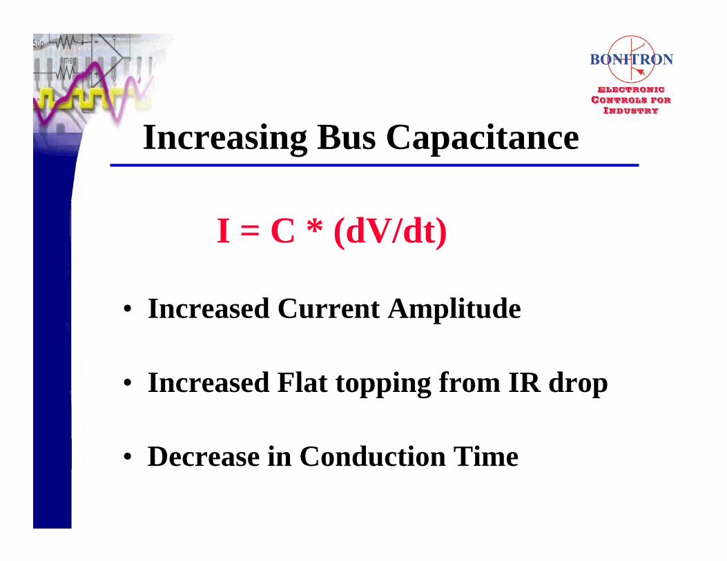
Increasing Bus Capacitance
• Increased Current Amplitude
• Increased Flat topping from IR drop
• Decrease in Conduction Time
I = C * (dV/dt)
Harmonic Solutions
What
• Multi Pulse Inputs
ie 12 pulse, 18 pulseRequires
• Additional Diode Bridge
• Phase shifted Transformer

Multi Pulse Parallel
• 1:1 Transformer w/phase shift• Easier to Implement• Balancing, Cancellation Problems• Lower Losses
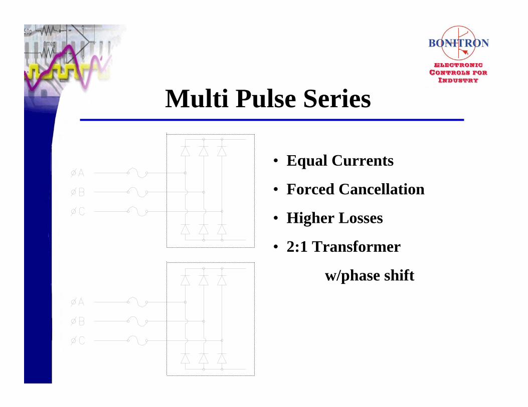
Multi Pulse Series
• Equal Currents
• Forced Cancellation
• Higher Losses
• 2:1 Transformer
w/phase shift
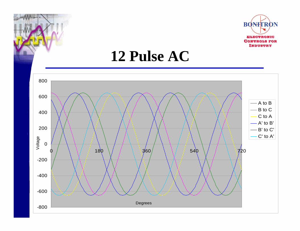
12 Pulse AC
-800
-600
-400
-200
0
200
400
600
800
0 180 360 540 720
A to BB to CC to AA' to B'B' to C'C' to A'
Volta
ge
Degrees
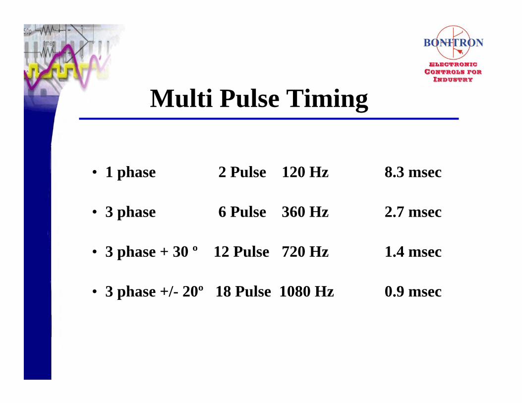
Multi Pulse Timing
• 1 phase 2 Pulse 120 Hz 8.3 msec
• 3 phase 6 Pulse 360 Hz 2.7 msec
• 3 phase + 30 º 12 Pulse 720 Hz 1.4 msec
• 3 phase +/- 20º 18 Pulse 1080 Hz 0.9 msec
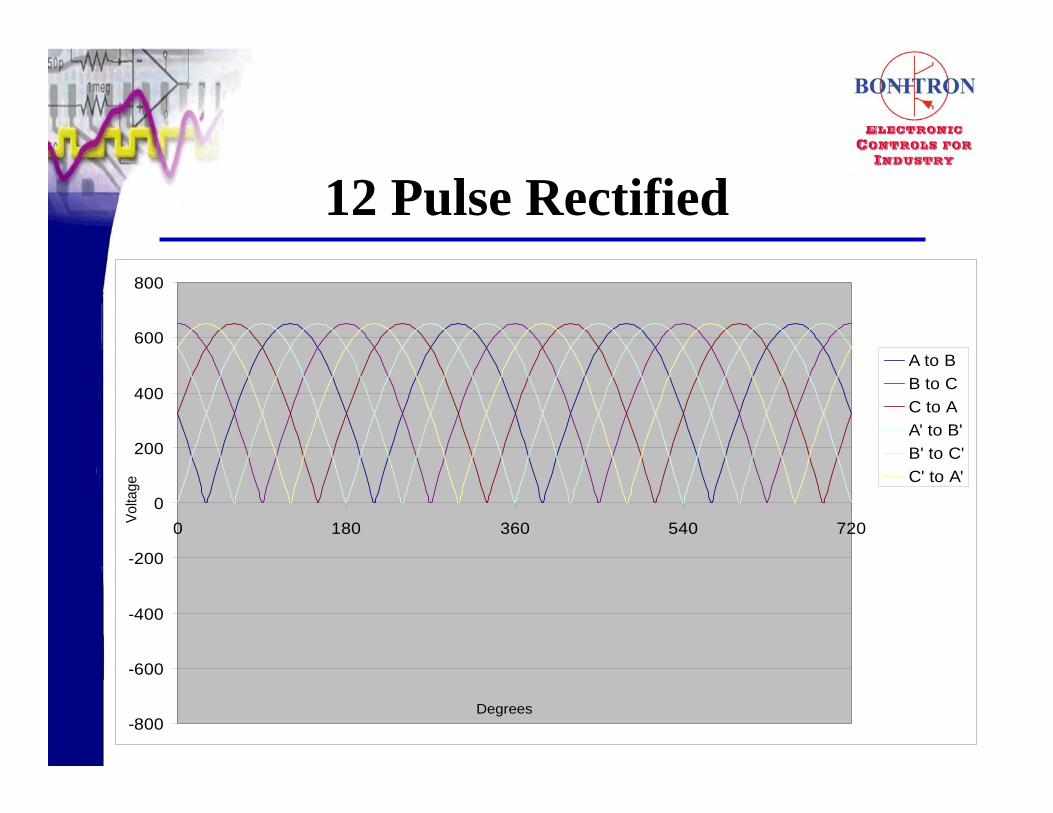
12 Pulse Rectified
-800
-600
-400
-200
0
200
400
600
800
0 180 360 540 720
A to BB to CC to AA' to B'B' to C'C' to A'
Volta
ge
Degrees

12 Pulse DCDC Bus
-800
-600
-400
-200
0
200
400
600
800
DC Bus
DegreesDegrees
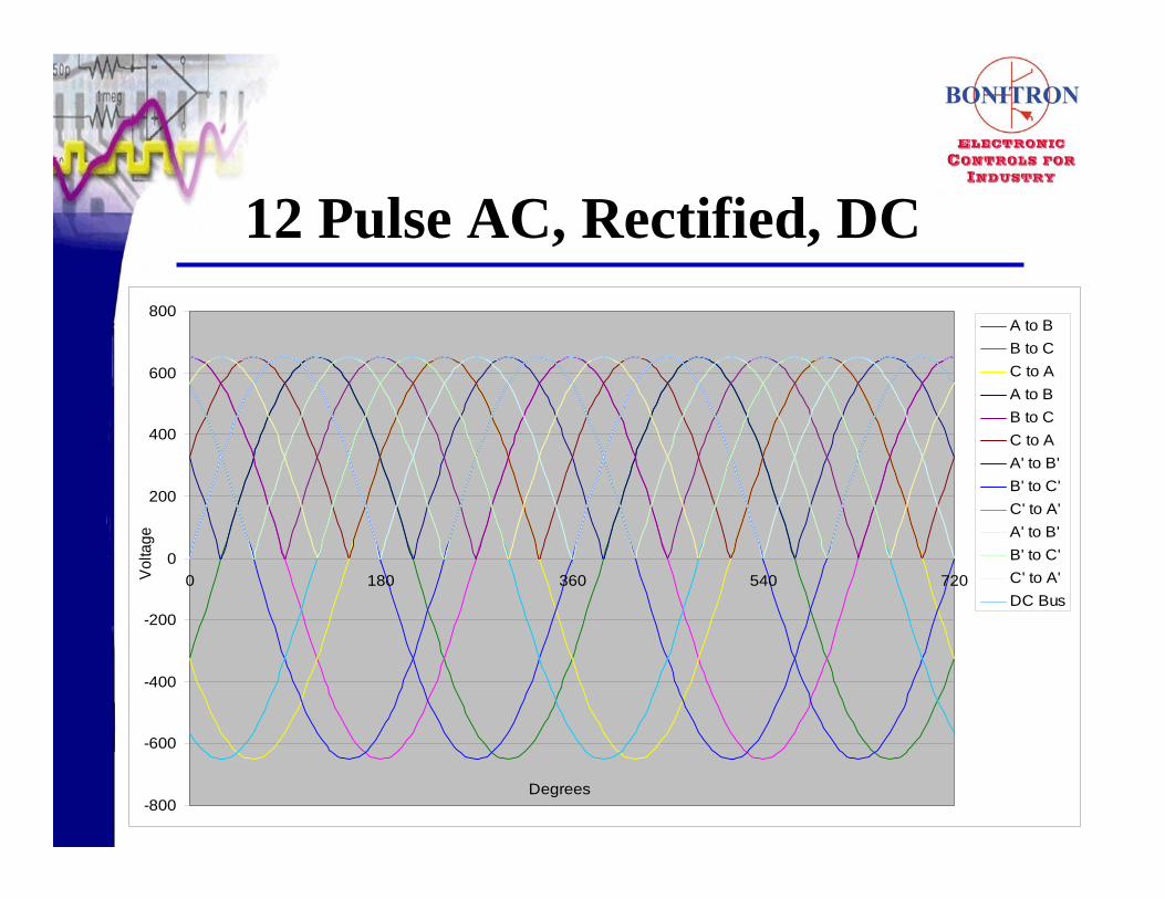
12 Pulse AC, Rectified, DC
-800
-600
-400
-200
0
200
400
600
800
0 180 360 540 720
A to BB to CC to AA to BB to CC to AA' to B'B' to C'C' to A'A' to B'B' to C'C' to A'DC Bus
Volta
ge
Degrees

Increasing Pulses
• Decrease in Current Amplitude
• Increased Cap refresh rate
• Harmonic Cancellation
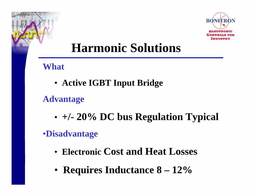
Harmonic SolutionsWhat
• Active IGBT Input Bridge
Advantage
• +/- 20% DC bus Regulation Typical•Disadvantage
• Electronic Cost and Heat Losses
• Requires Inductance 8 – 12%

Drive Schematic - Active
PWM gating to achieve Sinusoidal Current
PWM Waveform
• Requires Additional Impedance
• Requires Carrier Frequency Filter
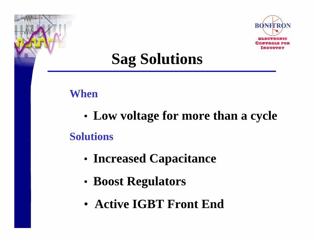
When
• Low voltage for more than a cycleSolutions
• Increased Capacitance
• Boost Regulators
• Active IGBT Front End
Sag Solutions

Sag Event Example
Bus Voltage
~595 VDC
640 VDC
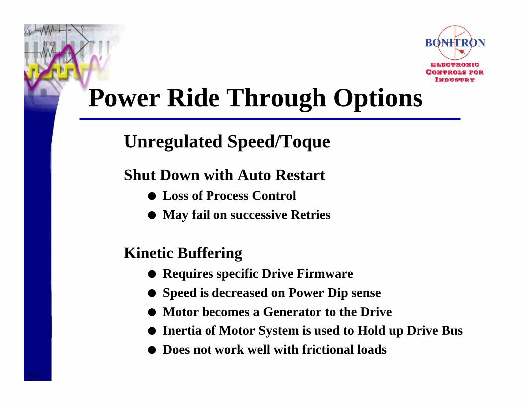
Power Ride Through Options
Shut Down with Auto RestartLoss of Process ControlMay fail on successive Retries
Kinetic BufferingRequires specific Drive FirmwareSpeed is decreased on Power Dip senseMotor becomes a Generator to the DriveInertia of Motor System is used to Hold up Drive BusDoes not work well with frictional loads
977032
Unregulated Speed/Toque
Power Ride Through OptionsRegulated Speed/Toque
Capacitance Backup
Chopper Boost Regulator
Chopper Boost Regulator with Capacitors
Active Front End
977032
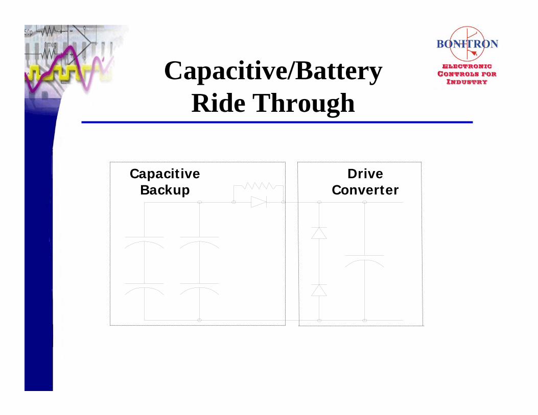
Capacitive/Battery Ride Through
Drive Converter
Capacitive Backup

Capacitive Energy Storage

Boost Chopper
BOOST REGULATOR DRIVECONVERTER

Drive Schematic - Active
PWM gating to achieve Sinusoidal Current

REACTOR
PWM REGEN
CONVERTER
MOTOR
DRIVE
CONVERTER & INVERTER
PWM Regen

• www.drivesmag.com
• www.epri-peac.com
• www.bonitron.com
Resources

QUESTIONS


