56
REDUCERBOX-TEN100412 | 98-0018712 | Version 1.2 EN System monitoring POWER REDUCER BOX Technical Description

REDUCERBOX-TEN100412 | 98-0018712 | Version 1.2 EN
System monitoringPOWER REDUCER BOX Technical Description


SMA Solar Technology AG Table of Contents
Technical Description REDUCERBOX-TEN100412 3
Table of Contents1 Notes on this Manual. . . . . . . . . . . . . . . . . . . . . . . . . . . . . . 61.1 Scope of Validity. . . . . . . . . . . . . . . . . . . . . . . . . . . . . . . . . . . . . 61.2 Target Group . . . . . . . . . . . . . . . . . . . . . . . . . . . . . . . . . . . . . . . 61.3 Symbols Used . . . . . . . . . . . . . . . . . . . . . . . . . . . . . . . . . . . . . . . 62 Safety . . . . . . . . . . . . . . . . . . . . . . . . . . . . . . . . . . . . . . . . . . 72.1 Appropriate Usage. . . . . . . . . . . . . . . . . . . . . . . . . . . . . . . . . . . 72.2 Safety Instructions . . . . . . . . . . . . . . . . . . . . . . . . . . . . . . . . . . . . 93 Unpacking. . . . . . . . . . . . . . . . . . . . . . . . . . . . . . . . . . . . . . 113.1 Scope of Delivery . . . . . . . . . . . . . . . . . . . . . . . . . . . . . . . . . . . 113.2 Identifying the Power Reducer Box . . . . . . . . . . . . . . . . . . . . . . 124 Mounting the Device . . . . . . . . . . . . . . . . . . . . . . . . . . . . . 134.1 Dimensions . . . . . . . . . . . . . . . . . . . . . . . . . . . . . . . . . . . . . . . . 134.2 Mounting Location . . . . . . . . . . . . . . . . . . . . . . . . . . . . . . . . . . 134.3 Mounting the Power Reducer Box on the Wall. . . . . . . . . . . . . 144.4 Mounting the Power Reducer Box on a Top Hat Rail. . . . . . . . 155 Electrical Connection . . . . . . . . . . . . . . . . . . . . . . . . . . . . . 165.1 Overview of the Connection Area . . . . . . . . . . . . . . . . . . . . . . 165.2 Connecting the Power Reducer Box to the Radio
Ripple Control Receiver . . . . . . . . . . . . . . . . . . . . . . . . . . . . . . 165.3 Connecting the Power Reducer Box to the Ethernet Network. . 185.3.1 Connection within a Local Network . . . . . . . . . . . . . . . . . . . . . . . . . . . . . . . 185.3.2 Connecting the Power Reducer Box Directly to a PC . . . . . . . . . . . . . . . . . . 19
6 Getting started . . . . . . . . . . . . . . . . . . . . . . . . . . . . . . . . . . 206.1 Connecting the Power Supply. . . . . . . . . . . . . . . . . . . . . . . . . . 206.2 Network Settings. . . . . . . . . . . . . . . . . . . . . . . . . . . . . . . . . . . . 206.2.1 Setting the PC to the Standard Network Settings of the Power Reducer Box. 21

Table of Contents SMA Solar Technology AG
4 REDUCERBOX-TEN100412 Technical Description
6.2.2 Setting the Power Reducer Box to the Local Network Settings . . . . . . . . . . . 236.2.3 Connecting the Power Reducer Box to the Local Network . . . . . . . . . . . . . . 24
7 Operation . . . . . . . . . . . . . . . . . . . . . . . . . . . . . . . . . . . . . . 257.1 Log in to the Power Reducer Box . . . . . . . . . . . . . . . . . . . . . . . 257.2 LED Overview . . . . . . . . . . . . . . . . . . . . . . . . . . . . . . . . . . . . . . 267.3 Overview of the Program Interface. . . . . . . . . . . . . . . . . . . . . . 277.4 Main Menu. . . . . . . . . . . . . . . . . . . . . . . . . . . . . . . . . . . . . . . . 277.5 Context Menu . . . . . . . . . . . . . . . . . . . . . . . . . . . . . . . . . . . . . . 287.6 Device Status . . . . . . . . . . . . . . . . . . . . . . . . . . . . . . . . . . . . . . 287.6.1 Updating the Device Status. . . . . . . . . . . . . . . . . . . . . . . . . . . . . . . . . . . . . . 297.7 Events . . . . . . . . . . . . . . . . . . . . . . . . . . . . . . . . . . . . . . . . . . . . 297.7.1 Filtering and Displaying Events . . . . . . . . . . . . . . . . . . . . . . . . . . . . . . . . . . . 297.7.2 Downloading Events . . . . . . . . . . . . . . . . . . . . . . . . . . . . . . . . . . . . . . . . . . . 307.7.3 Saving Events to an SD Card . . . . . . . . . . . . . . . . . . . . . . . . . . . . . . . . . . . . 307.8 WebBox Registration . . . . . . . . . . . . . . . . . . . . . . . . . . . . . . . . 317.8.1 Registering Sunny WebBox . . . . . . . . . . . . . . . . . . . . . . . . . . . . . . . . . . . . . 317.8.2 Deleting / Editing Sunny WebBox . . . . . . . . . . . . . . . . . . . . . . . . . . . . . . . . 327.9 Configuring the System States . . . . . . . . . . . . . . . . . . . . . . . . . 337.9.1 Setting Active Power Limitation . . . . . . . . . . . . . . . . . . . . . . . . . . . . . . . . . . . 347.9.2 Setting the Reactive Power Setpoint . . . . . . . . . . . . . . . . . . . . . . . . . . . . . . . 357.9.3 Setting the cos Phi Setpoint . . . . . . . . . . . . . . . . . . . . . . . . . . . . . . . . . . . . . . 357.9.4 Setting Combined Parameters . . . . . . . . . . . . . . . . . . . . . . . . . . . . . . . . . . . . 367.9.5 Setting General System States . . . . . . . . . . . . . . . . . . . . . . . . . . . . . . . . . . . 36
8 Settings . . . . . . . . . . . . . . . . . . . . . . . . . . . . . . . . . . . . . . . . 388.1 Setting the Password. . . . . . . . . . . . . . . . . . . . . . . . . . . . . . . . . 388.2 Resetting Password . . . . . . . . . . . . . . . . . . . . . . . . . . . . . . . . . . 388.3 Setting Network . . . . . . . . . . . . . . . . . . . . . . . . . . . . . . . . . . . . 398.3.1 Static Network Settings . . . . . . . . . . . . . . . . . . . . . . . . . . . . . . . . . . . . . . . . . 398.3.2 Setting Date and Time. . . . . . . . . . . . . . . . . . . . . . . . . . . . . . . . . . . . . . . . . . 408.3.3 Setting the Log File . . . . . . . . . . . . . . . . . . . . . . . . . . . . . . . . . . . . . . . . . . . . 40

SMA Solar Technology AG
Technical Description REDUCERBOX-TEN100412 5
9 Service Functions . . . . . . . . . . . . . . . . . . . . . . . . . . . . . . . . 419.1 Firmware Update via SD Card . . . . . . . . . . . . . . . . . . . . . . . . . 419.2 Stopping the Power Reducer Box . . . . . . . . . . . . . . . . . . . . . . . 419.3 Resetting the Power Reducer Box . . . . . . . . . . . . . . . . . . . . . . . 4210 Maintenance and Care . . . . . . . . . . . . . . . . . . . . . . . . . . . 4310.1 Maintenance. . . . . . . . . . . . . . . . . . . . . . . . . . . . . . . . . . . . . . . 4310.2 Care . . . . . . . . . . . . . . . . . . . . . . . . . . . . . . . . . . . . . . . . . . . . . 4311 Decommissioning . . . . . . . . . . . . . . . . . . . . . . . . . . . . . . . . 4411.1 Dismounting the Power Reducer Box . . . . . . . . . . . . . . . . . . . . 4411.2 Packing the Power Reducer Box . . . . . . . . . . . . . . . . . . . . . . . . 4411.3 Disposal of the Power Reducer Box . . . . . . . . . . . . . . . . . . . . . 4412 Troubleshooting . . . . . . . . . . . . . . . . . . . . . . . . . . . . . . . . . 4512.1 Meaning of the LEDs. . . . . . . . . . . . . . . . . . . . . . . . . . . . . . . . . 4512.2 Explanation of the LEDs at the Ethernet Connection . . . . . . . . . 4713 Technical Data . . . . . . . . . . . . . . . . . . . . . . . . . . . . . . . . . . 4814 Accessories . . . . . . . . . . . . . . . . . . . . . . . . . . . . . . . . . . . . . 5014.1 SD Cards . . . . . . . . . . . . . . . . . . . . . . . . . . . . . . . . . . . . . . . . . 5015 Contact . . . . . . . . . . . . . . . . . . . . . . . . . . . . . . . . . . . . . . . . 51

Notes on this Manual SMA Solar Technology AG
6 REDUCERBOX-TEN100412 Technical Description
1 Notes on this ManualThis manual describes how to install, mount and operate the Power Reducer Box. Store this manual where it can be accessed at all times.
1.1 Scope of ValidityThis manual applies to firmware versions 1.5.2 and later.
1.2 Target GroupThis manual is for qualified personnel and the user. Some tasks described in this manual may only be performed by qualified personnel. These tasks are identified with safety warnings.
1.3 Symbols UsedThe following types of safety precautions and general information appear in this document as described below.
DANGER!
DANGER indicates a hazardous situation which, if not avoided, will result in death or serious injury.WARNING!
WARNING indicates a hazardous situation which, if not avoided, could result in death or serious injury.CAUTION!
CAUTION indicates a hazardous situation which, if not avoided, could result in minor or moderate injury.NOTICE!
NOTICE indicates a situation that can result in property damage if not avoided.InformationInformation provides tips that are valuable for the optimal installation and operation of your product.

SMA Solar Technology AG Safety
Technical Description REDUCERBOX-TEN100412 7
2 Safety2.1 Appropriate UsageWith the Power Reducer Box it is possible to implement active power limitation or reactive power setpoint in accordance with the requirements of the grid safety management (GSM) for a PV system. For this four digital states (e.g. of a radio ripple control receiver) are able to be imported with the Power Reducer Box and the inverters can be set according to the specifications of the utility operator.The four input ports are freely configurable via the integrated web interface. If a signal from the radio ripple control receiver is present, the Power Reducer Box analyzes the signal and relays an instruction via the Ethernet network to the registered Sunny WebBox devices. Activated Sunny WebBox devices transfer the instruction to the connected inverters. Events are recorded onto the internal memory of the Power Reducer Box. Additionally it is possible to write events onto an SD card or download events via the web interface.
Function Overview of the Power Reducer Box• Integrated web server (for configuration of the Power Reducer Box).• Log book, in which every event is saved along with a time stamp.• HTTP download of the events in csv format.• Support of up to 50 Sunny WebBox devices.• Saving of events onto SD card.

Safety SMA Solar Technology AG
8 REDUCERBOX-TEN100412 Technical Description
Supported Devices• All WebBox devices with firmware version 1.45 and later.
– The transmission protocol of your system must be set to SMA-NET.– The Sunny WebBox devices must not be operated in DHCP mode.
You can find a current list of all inverters supported by the Power Reducer Box on the Web interface of the Power Reducer Box ("Status configuration > Compatibility list") or in the download section of www.SMA.de/en.If you have further questions regarding supported inverters, please contact the SMA Service Line.Operating Modes
• Active Power Limitation– Implementation of the instruction for power limitation in less than one minute.– Configurable delay time for reconnection to the 20 kV grid.
• Setpoint for Reactive Power Output together with Active Power Output– fixed power factor cos Phi (static parameter).– fixed reactive power in % of the maximum possible reactive power (static parameter).
The Power Reducer Box is only suitable for use with original accessories from SMA Solar Technology or with accessories recommended by SMA Solar Technology. Please also refer to the technical data of the Power Reducer Box.
Active Power Limitation to 0 %At an active power limitation to 0 % the inverters cannot be completely dimmed to 0 watts. A low residual power will continue to be fed-in depending on the inverter type in use.

SMA Solar Technology AG Safety
Technical Description REDUCERBOX-TEN100412 9
2.2 Safety InstructionsElectrical Connection
WARNING!Risk of lethal electric shock as a result of incorrect working on the Power Reducer Box.
• All work on the Power Reducer Box may only be carried out by qualified personnel.
NOTICE!Electrostatic discharges can damage the Power Reducer Box.
• All installation work on the Power Reducer Box must be carried out by qualified personnel.
• Avoid coming into contact with components' connections and plug contacts.• Ground yourself before working on the device.
NOTICE!Safety-relevant parameters
You can change the safety-relevant inverter parameters of your PV system using the Power Reducer Box. Usually, these parameters may only be changed upon consultation with the energy supplier into whose grid you are feeding.In case of doubt, please contact your energy supplier.

Safety SMA Solar Technology AG
10 REDUCERBOX-TEN100412 Technical Description
Operating InstructionsInverters not supported in the PV systemInverters not supported do not implement the parameters via the Power Reducer Box. The parameters of the utility operator can however be achieved. For this the status configuration of the Power Reducer Box must be adjusted so that the output of the supported inverters is more strongly controlled.If the utility operator requires an active power limitation of 0 %, the unsupported inverters must be disconnected via a suitable switching unit.In case of doubt, please contact your utility operator or the SMA Service Line before you commission the Power Reducer Box.No automatic firmware update for registered Sunny WebBox devicesWhen using the Power Reducer Box for managing feed-in, the automatic firmware update must be deactivated in all Sunny WebBox devices that are to be registered. Please note that the specifications of the utility operator cannot be implemented during the Sunny WebBox update process. No DHCP mode in the registered Sunny WebBox devicesIn the case of changing IP addresses in the WebBox devices (e.g. in DHCP networks) the Power Reducer Box does not function correctly. Convert all Sunny WebBox devices to be registered by the Power Reducer Box to static IP addresses.Data traffic via the RPC interfaceLimitation instructions from the Power Reducer Box are sent via the Sunny WebBox RPC interface. Avoid additional data traffic via the Sunny WebBox RPC interface, so as not to compromise the speed of the limitation instructions.JavaScriptJavaScript must be activated in your browser!
Data securityYou can connect the Power Reducer Box to the internet. This, however, carries a security risk. SMA recommends changing the login password after the initial installation in order to protect it from unauthorized access by third parties. Select a number-letter combination with at least 8 characters for your password (see section 8.1 ”Setting the Password.” (page 38)).

SMA Solar Technology AG Unpacking
Technical Description REDUCERBOX-TEN100412 11
3 Unpacking3.1 Scope of DeliveryCheck the delivery for completeness and any visible external damage. Please contact your dealer if the delivery is not complete or you find any damage.
Position Quantity DesignationA 1 Power Reducer BoxB 1 Plug-in power supply with four adaptorsC 1 Red Ethernet cable (patch cable)D 1 Blue Ethernet cable (crossover cable)E 1 ScrewdriverF 2 ScrewsG 2 Wall anchorH 1 Technical description with drilling template and compatibility listI 1 Pre-assembled cable (length 2.5 m) with 7 pole socket
(for the connection of the radio ripple control receiver)

Unpacking SMA Solar Technology AG
12 REDUCERBOX-TEN100412 Technical Description
3.2 Identifying the Power Reducer BoxType PlateYou can identify the Power Reducer Box using the type plate. The type plate can be found on the underside of the enclosure. It contains information regarding the specific characteristics of the device, serial number, version and MAC address.Firmware VersionThe firmware version can be found on the Power Reducer Box web interface in the lower left corner.

SMA Solar Technology AG Mounting the Device
Technical Description REDUCERBOX-TEN100412 13
4 Mounting the DeviceThe Power Reducer Box can be mounted on a wall. If you choose to mount the device on a wall, you can either mount it directly to the wall or on top hat rails.
4.1 Dimensions
4.2 Mounting LocationObserve the following ambient conditions for the Power Reducer Box:
• The Power Reducer Box is only suitable for mounting in enclosed spaces.• The ambient temperature must be between -20 °C and +60 °C during operation.• The Power Reducer Box should be protected from dust, wet conditions, corrosive substances
and vapors.• The cable length of the digital connection between the Power Reducer Box and the radio ripple
control receiver may be a maximum of 3 m.• The device should be located near to a 230 V socket.• The cable feeds require approx. 15 cm of space below the enclosure.• Lay the cables so that they do not disconnect due to their own weight. • Do not cover the Power Reducer Box. This can lead to heat accumulation in the device. • You can mount the Power Reducer Box together with the necessary network technology
(e.g. network switch, router, power supply) in one enclosure.

Mounting the Device SMA Solar Technology AG
14 REDUCERBOX-TEN100412 Technical Description
4.3 Mounting the Power Reducer Box on the Wall.Mounting Accessories Provided
1. Determine the installation site taking into consideration the installation location and space required.
2. Determine the position of the Power Reducer Box on the wall and mark the drill holes with a pen (see section 4.1 ).
3. Drill the holes (diameter 6 mm) at the marked positions and insert wall anchors.
4. Screw in the screws and leave about a 6 mm clearance between the screw head and the wall.
5. Hang the Power Reducer Box on the screws.
☑ The Power Reducer Box is mounted.
Position Quantity DesignationA 2 ScrewsB 2 Wall anchor

SMA Solar Technology AG Mounting the Device
Technical Description REDUCERBOX-TEN100412 15
4.4 Mounting the Power Reducer Box on a Top Hat Rail.No additional mounting equipment is necessary in order to mount the Power Reducer Box onto a top hat rail.1. Hook the Power Reducer Box with both lower brackets under the lower edge of the top hat rail.2. Press the Power Reducer Box upwards and snap the top hat rail into the upper brackets.
☑ The Power Reducer Box is mounted.

Electrical Connection SMA Solar Technology AG
16 REDUCERBOX-TEN100412 Technical Description
5 Electrical Connection
5.1 Overview of the Connection Area
All other connections on the Power Reducer Box have no function.
5.2 Connecting the Power Reducer Box to the Radio Ripple Control Receiver
WARNING!Risk of lethal electric shock as a result of incorrect working on the Power Reducer Box.
• All work on the Power Reducer Box may only be carried out by qualified personnel.
Position DesignationA Connection for the plug-in power supplyB AUXCOM for connection to the radio ripple control receiverC Ethernet connectionD SD card slot
NOTICE!Damage to the Power Reducer Box or the radio ripple control receiver due to incorrect connections.
• The connection of the Power Reducer Box to a radio ripple control receiver may only be carried out by qualified personnel.

SMA Solar Technology AG Electrical Connection
Technical Description REDUCERBOX-TEN100412 17
This section describes the connection of the Power Reducer Box to a radio ripple control receiver. The configuration of the radio ripple control receiver depends on the device and manufacturer.Digital Output Port of the Radio Ripple Control Receiver
1. Connect the pre-assembled cable to the radio ripple control receiver. You will find the wiring layout in the following diagram.
NOTICE!Damage to the Power Reducer Box due to too high input voltages.
• Use the +5 V wire from PIN 6 of the AUXCOM terminal for the control of the inputs via the relay contacts.
• Do not use external power supplies.
Insulated conductor color (DIN 47100 without color repetition)
Signal AUXCOM configuration Description
gray +5 V 6 Power supply (+5 V)white K1 1 Relay contact 1brown K2 2 Relay contact 2green K3 4 Relay contact 3yellow K4 5 Relay contact 4

Electrical Connection SMA Solar Technology AG
18 REDUCERBOX-TEN100412 Technical Description
2. Plug the 7 pole plug into the AUXCOM terminal of the Power Reducer Box.
☑ The Power Reducer Box is connected to the radio ripple control receiver.
5.3 Connecting the Power Reducer Box to the Ethernet NetworkThe Power Reducer Box is equipped with an integrated network connection, which enables it to be connected to any Ethernet network. The terminal supports both Ethernet and Fast Ethernet networks (10 / 100 Mbit/s). The speed is switched automatically depending on the connected switch, router or PC.
5.3.1 Connection within a Local Network
1. Connect the Power Reducer Box to the network with the red Ethernet cable via the Ethernet terminal of the enclosure. The receiver (switch, router) normally has the same designation. If you have questions then please read the receiver manual.
Standard configuration:Active power limitation for K1 = 0 %, K2 = 30 %, K3 = 60 % and K4 = 100 %.
Initial start-upPlease note that before integration of the Power Reducer Box into a local network, you must configure the Power Reducer Box for your network (see section 6 ”Getting started” (page 20)).

SMA Solar Technology AG Electrical Connection
Technical Description REDUCERBOX-TEN100412 19
5.3.2 Connecting the Power Reducer Box Directly to a PC
1. Connect the Power Reducer Box directly to the PC via the Ethernet terminal of the enclosure. For this, use the blue Ethernet cable. The PC should normally have the same designation. If necessary, refer to the PC manual.
Ethernet cabling recommendationsIf the delivered Ethernet cable is too short, please note the following when purchasing a longer cable:
• You require a patch cable.• Unnecessarily long cables have an adverse effect on the signal quality. The
maximum permitted cable length for Ethernet cable is 100 m per segment.• Use high quality cable, at least category 5 (SFTP Cat 5) or higher shielded twisted
pair.
Ethernet cabling recommendationsIf the delivered Ethernet cable is too short, please note the following when purchasing a longer cable:
• You require a crossover cable.• Unnecessarily long cables have an adverse effect on the signal quality. The
maximum permitted cable length for Ethernet cable is 100 m per segment.• Use high quality cable, at least category 5 (SFTP Cat 5) or higher shielded twisted
pair.

Getting started SMA Solar Technology AG
20 REDUCERBOX-TEN100412 Technical Description
6 Getting startedBefore you use the Power Reducer Box for the first time, you must integrate it into your Ethernet network. For this you must connect the Power Reducer Box directly to the PC (see section 5.3.2 ”Connecting the Power Reducer Box Directly to a PC” (page 19)).
6.1 Connecting the Power SupplyOnly connect the plug-in power supply after all necessary electrical connections to the Power Reducer Box have been made (Ethernet connection, radio ripple control receiver). Upon connection to the plug-in power supply the Power Reducer Box starts and is operationally ready after approx. 60 - 90 seconds. Connecting the Plug-in Power Supply
1. Check the connections.2. Connect the DC plug connector of the power supply unit to the DC connection of the Power
Reducer Box.3. Insert the plug-in power supply into the power outlet.☑ The Power Reducer Box starts.
6.2 Network SettingsChanging network settingsDo not change any network settings either on your PC or the Power Reducer Box if you are not certain about the consequences of the changes. Changing certain values via the PC can corrupt your existing network partially or completely. In severe cases, the Power Reducer Box can no longer be accessed from the PC. You will need the corresponding user authorizations on the PC in order to be able to change network settings. If in doubt, contact the network administrator.
Operating systemThe following descriptions apply to Windows XP with Internet Explorer 6. The descriptions are similar and should be recognizable when using Windows 2000 / Vista or Internet Explorer 5/7/8..

SMA Solar Technology AG Getting started
Technical Description REDUCERBOX-TEN100412 21
The following steps are necessary for integrating the Power Reducer Box into a local network:• Set the PC to the standard network settings of the Power Reducer Box, see section 6.2.1 ”Setting
the PC to the Standard Network Settings of the Power Reducer Box.” (page 21).• Set the Power Reducer Box to the local network settings (see section 6.2.2 ”Setting the Power
Reducer Box to the Local Network Settings” (page 23)).• Connect the Power Reducer Box to the local network (see section 6.2.3 ”Connecting the Power
Reducer Box to the Local Network” (page 24)).
6.2.1 Setting the PC to the Standard Network Settings of the Power Reducer Box.In order to set the PC to the standard network settings of the Power Reducer Box, the following steps are required:
• Setting up an IP address on the PC.• Setting up the proxy server advanced rules of the browser (e.g. Internet Explorer).
1. Connection of the Power Reducer Box directly to the PC (see section 5.3.2 ”Connecting the Power Reducer Box Directly to a PC” (page 19)).
2. Connecting the Power Reducer Box to the power supply (see section 6.1 ”Connecting the Power Supply” (page 20)).
Setting up an IP Address on the PC3. In Windows, select "Start > Settings > Network connections > LAN connection".
☑ The "LAN connection status" window opens.4. In the "General" register, select the [Properties] button.
☑ The window "LAN connection properties" opens.5. In the "General" register, select the "Internet protocol (TCP/IP)" and then select [Properties].
6. Select "Use following IP address".7. The following specifications are necessary:
Noting settings in the window "Internet protocol properties (TCP/IP)".Note the current settings in the window "Internet protocol properties (TCP/IP)" before changing it to the settings of the Power Reducer Box. Upon configuration of the Power Reducer Box re-enter the noted settings if necessary in order to recreate the original network configuration.
IP address: 10.100.2.70Subnet mask: 255.0.0.0

Getting started SMA Solar Technology AG
22 REDUCERBOX-TEN100412 Technical Description
8. Delete any entries in the "Standard gateway", "Preferred DNS server", and "Alternative DNS server" boxes.
9. Select [OK].☑ The window "Internet protocol properties (TCP/IP)" closes.
10. In the window "LAN connection properties", select [Close].11. In the window "LAN connection status", select [Close].Proxy Server Exceptions in Internet Explorer12. Start Internet Explorer.13. In Internet Explorer, select "Tools > Internet Options".
☑ The "Internet Options" window opens.14. Select the "Connections" tab, then click [Settings].15. If there is no checkmark in the box before "Use a proxy server for your LAN", go to step 16,
otherwise click [Advanced] and carry out the following instructions:– Enter "10.100.*" at the end of the entry in the "Do not use proxy server for addresses
beginning with" field; use the semicolon as separator if required. – Confirm your settings in each of the three windows by clicking [OK].
16. If there is no checkmark in the box before "Use a proxy server for your LAN", click [Cancel] twice.
17. Call up the Power Reducer Box start page by entering http://10.100.2.1 in the address bar of your browser.☑ The Power Reducer Box start page appears.
☑ The PC is set to the standard network settings of the Power Reducer Box.Now set the Power Reducer Box to the local network settings (see section 6.2.2 ”Setting the Power Reducer Box to the Local Network Settings” (page 23)).
No connection to the Power Reducer BoxIf no connection to the Power Reducer Box is established, check the electrical connection (see section 5.3.2 ”Connecting the Power Reducer Box Directly to a PC” (page 19)).

SMA Solar Technology AG Getting started
Technical Description REDUCERBOX-TEN100412 23
6.2.2 Setting the Power Reducer Box to the Local Network SettingsFor delivery, the static network settings of the Power Reducer Box are set to the following values:
The Power Reducer Box should preferably have a static IP address in your network.Static Network Settings1. Log in as "installer" on the start page of the Power Reducer Box (see section 7.1 ”Log in to the
Power Reducer Box” (page 25)).☑ The "Plant overview" page opens.
2. Select "Network and system settings" in the main menu.3. Enter the following settings in "Network settings":
– In the "Acquire IP address" field select the value "static".
4. Enter the IP address into the "IP address" field, at which the Power Reducer Box shall be accessed.
5. In the "Subnet mask" field, enter the subnet mask of your network. This mask limits the Ethernet network to certain IP addresses and separates network areas from each other.
6. In the "Gateway address" field, enter the gateway address of your network. The gateway address is the IP address of the device that establishes the connection with the Internet. Usually, the address of the router is entered here.
7. In the "DNS server address" field, enter the address of the DNS server. The DNS (Domain Name System) server translates Internet addresses (e.g. www.SunnyPortal.com) into the respective IP addresses. Internet addresses are easier to remember than IP addresses. Type in the DNS server address your Internet service provider has provided you with or, alternatively, enter the IP address of your router.
8. Select [Save].☑ The Ethernet interface of the Power Reducer Box is configured.
9. Select [Logout]☑ The Power Reducer Box is set to the local network settings.
You may now connect the Power Reducer Box to your local network (see section 6.2.3 ”Connecting the Power Reducer Box to the Local Network” (page 24)).
IP address: 10.100.2.1Subnet mask: 255.0.0.0Port: 80
Network administratorIf your local Ethernet is managed by a network administrator, contact him/her before integrating the Power Reducer Box into your network.
Assigning IP addressesOnly one instance of each IP address is permissible in the Ethernet network. The last part of the IP address must never be 0 or 255.

Getting started SMA Solar Technology AG
24 REDUCERBOX-TEN100412 Technical Description
Dynamic Network SettingsYou can also integrate the Power Reducer Box into your Ethernet network via DHCP. For this an active DHCP server must be available in your local network.1. Log in as "installer" on the start page of the Power Reducer Box (see section 7.1 ”Log in to the
Power Reducer Box” (page 25)).☑ The "Plant overview" page opens.
2. Select "Network and system settings" in the main menu.3. In the "Acquire IP address" field select the value "dynamic".4. Select [Save].☑ The Power Reducer Box acquires its IP address from the local network DHCP server.
6.2.3 Connecting the Power Reducer Box to the Local Network1. Stop the Power Reducer Box (see section 9.2 ”Stopping the Power Reducer Box” (page 41)).2. Remove the crossover cable.3. Connect the Power Reducer Box to the local network (see section 5.3.1 ”Connection within a
Local Network” (page 18)).4. Connect the power supply (see section 6.1 ”Connecting the Power Supply” (page 20)).5. If necessary, reset the PC to the local network settings.☑ The Power Reducer Box is connected to the local network.
Retrieving the IP address dynamically (DHCP)If the Power Reducer Box has been integrated into your network via DHCP, you must determine the IP address via the router. We recommend extending the lease of the assigned IP address. If necessary, please contact your network administrator. Generally a static network setting should be preferred.

SMA Solar Technology AG Operation
Technical Description REDUCERBOX-TEN100412 25
7 Operation7.1 Log in to the Power Reducer BoxLogin Page
To change the Power Reducer Box settings, you must first log in. The Power Reducer Box differentiates between three user groups:
• User• Installer• Service
In order to prevent two users effecting contradictory settings at the same time, only one user can ever be logged on to the Power Reducer Box at one time.
Position DesignationA Device statusB Language selectionC Login areaD Serial number and software versionE Last actualization of page contents
Service user groupThe Service user group is exclusively restricted to SMA Service employees.

Operation SMA Solar Technology AG
26 REDUCERBOX-TEN100412 Technical Description
The "Installer" user group has the following rights in addition to the rights of the "User" user group.• Changing the status configuration.• Registration and administration of Sunny WebBox devices in the Power Reducer Box.• Resetting the "User" user group password.
Log in to the Power Reducer Box
1. In the browser, enter the IP address of your Power Reducer Box.☑ The Power Reducer Box login page appears. If the login page does not open, check the
electrical connection (page 16) and the network configuration (page 18).2. Select the desired language in the "Language" field.3. Select the user group in the "User group" field.4. Enter the password in the "Password" field.5. Select [Login].☑ The Power Reducer Box start page appears.
7.2 LED Overview
Factory settings:User group: User InstallerPassword 0000 1111
SafetyOnce you have logged on for the first time, change your password in order to protect from unauthorized access (see section 8.1 ).
Legend MeaningPOWER COMMAND Validation of the parameterPOWER STATUS Status of the power limitationWEBBOXCOM Communication with Sunny WebBoxNETCOM Activity in the Ethernet networkSD CARD Status of the SD cardSYSTEM Readiness for operationPOWER Power supply

SMA Solar Technology AG Operation
Technical Description REDUCERBOX-TEN100412 27
7.3 Overview of the Program InterfaceThe Power Reducer Box is operated via the integrated web interface. The following figure displays the segmentation of the web interface.Start Page of the Web Interface
7.4 Main Menu
Position DesignationA Main MenuB Context MenuC Contents section
Button Designation FunctionStatus This button opens the "Status" page
(see section 7.6 ”Device Status” (page 28)).
Events This button opens the "Events" page (see section 7.7 ”Events” (page 29)).
Network and system settings
This button opens the "Network and system settings" page of the Power Reducer Box.
Logout You can log out using this button.

Operation SMA Solar Technology AG
28 REDUCERBOX-TEN100412 Technical Description
7.5 Context Menu
7.6 Device StatusOn the "Status" page an overview of the current status of the PV system is given in the upper area. The following information is shown:
In the lower area, all of the Sunny WebBox devices registered to the Power Reducer Box are listed with their current communication status. A Sunny WebBox can have the following statuses:
Button FunctionWebBox registration This menu item opens the "WebBox registration" page
(see section 7.8 ”WebBox Registration” (page 31)).Status configuration This menu item opens the "Status configuration" page
(see section 7.9 ”Configuring the System States” (page 33)).Password settings This menu item opens the "Password settings" page.
Device status The device status displays which overall status the Power Reducer Box is in.
Operating mode The operating mode displays which parameter the Power Reducer Box is currently implementing.
Setpoint (set) The Setpoint (set) displays which values have been configured in the Power Reducer Boy for the parameter.
Setpoint (current) The Setpoint (current) displays which values are currently being implemented.
Status of the input ports The status shows the current incoming signal of the radio ripple control receiver. K1 to K4 relate to the respective connected relays. If no signal is incoming, the value "Open" is displayed.
Display of the current status of the Power Reducer Box The device status is also displayed on the login page of the Power Reducer Box.
Symbol Status DescriptionOk Communication between Power Reducer Box and Sunny WebBox
is functioning correctly.
Unknown The communication status of the Sunny WebBox is currently unknown.
Failure There is a communication failure between the Power Reducer Box and the Sunny WebBox.

SMA Solar Technology AG Operation
Technical Description REDUCERBOX-TEN100412 29
7.6.1 Updating the Device Status
You can update the device status manually:1. Select "Status" in the main menu.2. Select [Update].☑ The device status will be updated.
7.7 EventsAll events of the Power Reducer Box, such as change to status or fault in communication, are logged and displayed on the "Events" page. All events are recorded in the internal memory. Once the internal memory has reached its capacity, the oldest events will be written over. In addition you have the possibility to save the events onto an SD card.
7.7.1 Filtering and Displaying Events1. Select "Events" in the main menu.
☑ The events of the current day are displayed.2. If necessary, filter the events. For this, a checkmark must be placed in the relevant field. Multiple
selection is possible. The following filter settings are possible:– Status change– Info– Warning– Disturbance– Error
3. Select time period.4. Select [Update].☑ The events in the desired time period are displayed.
In addition events can be downloaded directly (see section 7.7.2 ) or saved additionally onto an SD card (see section 7.7.3 ).
Automatic updating of the page contentsThe page contents are updated automatically every 30 seconds.

Operation SMA Solar Technology AG
30 REDUCERBOX-TEN100412 Technical Description
7.7.2 Downloading EventsYou can download events as text files in csv format via the web interface. However, only events are downloaded that have currently been displayed or filtered. The csv file uses UTF-8 character encoding.1. Select "Events" in the main menu. 2. Select [Download].3. Select save location and confirm. ☑ The events are downloaded.
7.7.3 Saving Events to an SD CardEvents can additionally be saved to an SD card. Recording of the events begins with the insertion of the SD card into the Power Reducer Box. If the SD card has reached its capacity, recording is stopped. Old data files are not overwritten on the SD card. The red blinking SD card LED displays if the SD card is full or write-protected.
All events are saved onto the SD card daily under the directory /Year/Month/Prefix_Year_Month_Day.csv. Example of a daily report for July 1, 2009 and the default prefix: /2009/07/PRB_09_07_01.csv. UTF-8 character encoding is used for all .csv files.1. Insert the SD card in the Power Reducer Box.☑ The events are saved additionally onto the SD card.
You can carry out further settings on the protocol file in the system settings of the Power Reducer Box (see section 8.3.3 ).
SD card compatibilityTo ensure that the SD card is functioning properly, use SD cards available from SMA. Compatibility with all SD cards available on the market cannot be guaranteed. SD cards with a capacity of above 2 GB and SDHC cards are not supported.
Formatting the SD cardOnly use SD cards which have been formatted with the FAT32 file system.
Loss of data upon removal of SD cardDo not remove the SD card while the SD CARD LED is blinking green or orange. This can damage the file system of the SD card and lead to data loss. Depending on the data quantity, the writing process can take some time (e.g. upon inserting an empty SD card).

SMA Solar Technology AG Operation
Technical Description REDUCERBOX-TEN100412 31
7.8 WebBox Registration
7.8.1 Registering Sunny WebBoxAll Sunny WebBox devices which are to be controlled by the Power Reducer Box must be registered via the web interface. The Sunny WebBox devices must not be operated in DHCP mode.1. Select "WebBox registration" in the context menu.2. Enter the settings for each Sunny WebBox to be registered in the upper area:
– In the "Name" field enter the name of the WebBox. The name can be freely assigned and serves the display on the "Status" page (maximum 20 characters). If no name is assigned, the IP address of the Sunny WebBox is registered as standard.
– In the "IP Address" field enter the IP address of the Sunny WebBox, under which it is to be reached. The Sunny WebBox must have a fixed IP address and must not be in DHCP mode.
– In the "Port" field enter the Web server port of the Sunny WebBox, under which it can be reached. Port 80 is set by default here.
3. Select [Add].☑ The newly registered Sunny WebBox appears in a list in the lower area.
You can enter further Sunny WebBox devices in the same way. Please note the maximum number of supported Sunny WebBox devices. Available Sunny WebBox devices can be deleted or edited (see section 7.8.2 ”Deleting / Editing Sunny WebBox” (page 32)).
The following settings may only be carried out by qualified personnel.
No removal or editing of Sunny WebBox devices during active implementation of the Power Reducer Box.Do not remove any Sunny WebBox devices and do not change any Sunny WebBox IP addresses in the Sunny WebBox registration, while an active power limitation ( < 100 %) or reactive power setpoint is active.
Valid Sunny WebBoxIt is not checked whether the Sunny WebBox address is valid. Check the status display on the "Status" page (see section 7.6 ) to see whether the Sunny WebBox has been correctly registered.
Operation SMA Solar Technology AG
32 REDUCERBOX-TEN100412 Technical Description
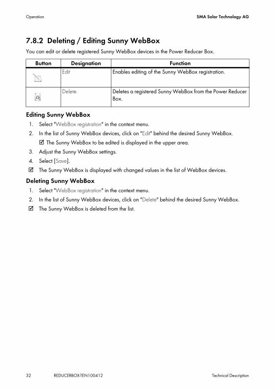
7.8.2 Deleting / Editing Sunny WebBoxYou can edit or delete registered Sunny WebBox devices in the Power Reducer Box.
Editing Sunny WebBox1. Select "WebBox registration" in the context menu.2. In the list of Sunny WebBox devices, click on "Edit" behind the desired Sunny WebBox.
☑ The Sunny WebBox to be edited is displayed in the upper area.3. Adjust the Sunny WebBox settings.4. Select [Save].☑ The Sunny WebBox is displayed with changed values in the list of WebBox devices.
Deleting Sunny WebBox1. Select "WebBox registration" in the context menu.2. In the list of Sunny WebBox devices, click on "Delete" behind the desired Sunny WebBox.☑ The Sunny WebBox is deleted from the list.
Button Designation FunctionEdit Enables editing of the Sunny WebBox registration.
Delete Deletes a registered Sunny WebBox from the Power Reducer Box.

SMA Solar Technology AG Operation
Technical Description REDUCERBOX-TEN100412 33
7.9 Configuring the System States
The assignment of the digital input ports to the system states takes place via the web interface. A maximum of 16 states can be configured. Of these, at least 2 states must be configured. If there is a state present which is not configured in the Power Reducer Box, it is rated as an error and logged.
The following settings may only be carried out by qualified personnel.
Standard configuration:Active power limitation for K1 = 0 %, K2 = 30 %, K3 = 60 % and K4 = 100 %

Operation SMA Solar Technology AG
34 REDUCERBOX-TEN100412 Technical Description
The following parameters can be configured:• Active Power Limitation• Reactive Power Setpoint• cos Phi setpoint
Additionally, the following combined parameters can be configured:• Active power limitation and reactive power setpoint• Active power limitation and cos Phi setpoint• Reactive power setpoint and cos Phi setpoint
7.9.1 Setting Active Power Limitation
In order to configure the active power limitation for a state of a relay, proceed as follows:1. Log in as "Installer".2. Select "Status configuration" in the context menu.3. Search for the entry of the state to be configured in the "Digital input port state" column.4. In the "Active" column place a checkmark alongside the state to be configured.
☑ The state is active. Upon saving it will be analyzed by the Power Reducer Box.5. Select the value "Active power limitation" of the state to be configured in the "Operating mode"
column.6. In the "Active power in %" column, enter the active power for the state to be considered for the
phases L1, L2 and L3 in percent.Different phases are only interpreted by inverters with multiple phases. Enter the same value for all phases in the case of single phase inverters.
7. Configure further states in the same way.8. Take on general settings of the system states (see section 7.9.5 ”Setting General System States”
(page 36)).9. Select [Save].☑ The active power limitation is set.
Configuring combined parametersPlease note that in the case of combined parameters (e.g. active power limitation and reactive power setpoint) the respective settings of the individual parameters must be made. In case of doubt, please contact SMA Solar Technology.
Active power limitation to 0 %At an active power limitation to 0 % the inverters cannot be completely dimmed to 0 watts. The inverter continues to feed in a low residual power.

SMA Solar Technology AG Operation
Technical Description REDUCERBOX-TEN100412 35
7.9.2 Setting the Reactive Power SetpointIn order to configure the reactive power setpoint for a state of a relay, proceed as follows:1. Log in as "Installer".2. Select "Status configuration" in the context menu.3. Search for the entry of the state to be configured in the "Digital input port state" column.4. In the "Active" column place a checkmark alongside the state to be configured.
☑ The state is active and will be analyzed by the Power Reducer Box upon saving.5. Select the value "Reactive power setpoint" of the state to be configured in the "Operating mode"
column.6. In the "Reactive power in %" column, enter the reactive power setpoint for the state to be
considered in percent for the phases L1, L2 and L3.Different phases are only interpreted by inverters with multiple phases. Enter the same value for all phases in the case of single phase inverters.
7. Configure further states in the same way.8. Take on general settings of the system states (see section 7.9.5 ”Setting General System States”
(page 36)).9. Select [Save].☑ The reactive power setpoint is set.
7.9.3 Setting the cos Phi SetpointIn order to configure the cos Phi setpoint for a state of a relay, proceed as follows:1. Log in as "Installer".2. Select "System states" in the context menu.3. Search for the entry of the state to be configured in the "Digital input port state" column.4. In the "Active" column place a checkmark alongside the state to be configured.
☑ The state is active and will be analyzed by the Power Reducer Box upon saving.5. In the "Parameters" column, select the "cos Phi setpoint" next to the state to be configured.6. Enter the cos Phi value for the phases L1, L2 and L3 in the "cos Phi" column for the state to be
configured.The cos Phi value can be between 0.10 and 1.00. Different phases are only interpreted by inverters with multiple phases (see inverter manual). Enter the same value for all phases in the case of single phase inverters.
7. Whether the cos Phi value is under-excited or over-excited is to be selected in the "Excitation" column.
8. Configure further states in the same way.

Operation SMA Solar Technology AG
36 REDUCERBOX-TEN100412 Technical Description
9. Take on general settings of the system states (see section 7.9.5 ”Setting General System States” (page 36)).
10. Select [Save].☑ The cos Phi setpoint is now set.
7.9.4 Setting Combined Parameters
In order to set combined parameters, the individual parameters must be configured respectively for one state of the relay.
• Active power limitation and reactive power setpoint• Active power limitation and cos Phi setpoint• Reactive power setpoint and cos Phi setpoint
7.9.5 Setting General System States1. Log in as "Installer".2. Select "Status configuration" in the context menu.3. In the "Error tolerance time" field, enter the desired error tolerance time, from when an invalid
input signal is recognized as an error. In practice it can be that during state change an undefined input signal appears for a short time, if, for example, two relays activate for 1 s simultaneously. The error tolerance time should be set to long enough so that no error message is generated during this transition of states.
4. In the field "Debouncing time" enter the desired debouncing time in milliseconds. The value states how long a signal must be present at a minimum of one input port, in order that it is recognized as such and then can be processed by the system. This setting prevents short impulses, caused by mechanical contact bounces, being falsely recognized as a signal during the state transition.
5. In the field "Time interval for changed parameter", enter the time interval in seconds in which the control command should be sent to the registered Sunny WebBox devices after the parameter of the radio ripple control receiver has changed. After the parameter has been reached, the Power Reducer Box will jump to the "Time interval for constant parameter". Example: When entering 60 seconds, the Power Reducer Box would transmit a control command with the changed parameter value to the registered Sunny WebBox devices every 60 seconds after a parameter has changed.
Configuring combined parametersPlease note that in the case of combined parameters (e.g. active power limitation and reactive power setpoint) the respective settings of the individual parameters must be made. In case of doubt, please contact SMA Solar Technology.

SMA Solar Technology AG Operation
Technical Description REDUCERBOX-TEN100412 37
6. Select the factor in the "Time interval for constant parameter" with which the value of the "Time interval for changed parameter" should be multiplied. The field "Time interval for constant parameter" defines at which interval the control command should be transmitted to the Sunny WebBox devices once the parameter of the radio ripple control receiver has been met.
7. In the field "Max. change during power increase" enter the maximum, percental change per minute upon lifting of an active power limitation (requirement for the reconnection of systems to the 20 kV grid: max. 10 % of the connection active power per minute.)1) .
8. In the field "Max. change by power decline" enter the maximum percental change per minute in accordance with a request for a active power limitation.
9. Enter the reference parameter for the inverters in the "Reference parameter" field. The reference parameter defines to which value the active power limitation will refer. Make sure that your connected inverters support the set reference parameter (see "Compatibility list").
10. Select [Save].☑ The configurations are saved.
1)Technical guideline "Generation systems on the medium voltage grid" BDEW (German Federal Association for Energy and Water) , June 2008

Settings SMA Solar Technology AG
38 REDUCERBOX-TEN100412 Technical Description
8 Settings8.1 Setting the Password.
1. Select "Password settings" in the context menu.2. In the "Change password" area, enter the respective settings:
– Enter the old password in the "Old password" field.– Enter the new password in the "New password" field.– Re-enter the new password in the "Repeat password" field.
3. Select [Save].☑ The settings are active from the next login.
8.2 Resetting Password1. Select "Password settings" in the context menu.2. In the "Reset password" area, select the user group that should be reset.3. Select [Reset] ☑ The password is reset to the factory installed password and is active from the next login.
Password securityIn order to increase the security, please note the following points when selecting a password:
• Minimum 8 characters• Mix upper and lower-case letters• Use numbers and special characters
Resetting passwords of other user groupsAdditionally, the "User" user group password can be reset in the "Installer" user group.

SMA Solar Technology AG Settings
Technical Description REDUCERBOX-TEN100412 39
8.3 Setting Network1. Select "Network and system settings" in the web interface. 2. Make a selection in the "Retrieve IP address" field.
The following selection is possible:
3. If "static" has been selected, continue with section 8.3.1 ”Static Network Settings” (page 39)4. If "dynamic" has been selected, then select [Save].
☑ The network of the Power Reducer Box is set.
8.3.1 Static Network Settings1. Select "Network and system settings" in the main menu.2. The "Retrieve IP address" field should be set to "static".3. Enter the IP address at which the Power Reducer Box can be accessed into the "IP address" field.
4. In the "Subnet mask" field, enter the subnet mask of your network. This mask limits the Ethernet network to certain IP addresses and separates network areas from each other.
5. In the "Gateway address" field, enter the gateway address of your network. The gateway address is the IP address of the device that establishes the connection with the Internet. Usually, the address of the router is entered here.
6. In the "DNS server address" field, enter the address of the DNS server. The DNS (Domain Name System) server translates Internet addresses (e.g. www.SunnyPortal.com) into the respective IP addresses. Internet addresses are easier to remember than IP addresses. Type in the DNS server address your Internet service provider has provided you with or, alternatively, enter the IP address of your router.
7. Select [Save].☑ The static network settings have been set.
Static Network settings have to be made manually.Dynamic Network settings are automatically acquired from the network (DHCP).
DHCP usageThe Power Reducer Box can only be accessed via its IP address. Before setting the Power Reducer Box to dynamic IP address assignment, check your DHCP server. The DHCP server must extend the lease of the assigned IP address. If the DHCP server assigns a new IP address after the lease has expired, we do not recommend using the DHCP server. DHCP servers can normally list all devices to which you have assigned an IP address. The Power Reducer Box can then be identified via its MAC address. You will find the MAC address of your Power Reducer Box on the type plate.
Assigning IP addressesOnly one instance of each IP address is permissible in the Ethernet network. The last part of the IP address must never be 0 or 255.

Settings SMA Solar Technology AG
40 REDUCERBOX-TEN100412 Technical Description
8.3.2 Setting Date and Time
1. Select "Network and system settings" in the main menu.2. Select the current date in Day-Month-Year format in the "New date: Day, Month, Year" field.3. Enter the current time in the format hours:minutes in the "New time (hh:mm) 24 hour format" field.4. Select the time zone in which the system is located in the "Time zone" field.5. Select [Save].☑ The date and time are set.
8.3.3 Setting the Log File1. Select "Network and system settings" in the main menu.2. Select the prefix, with which the file name of the log file should begin in the "Prefix for log files"
field.3. Select the language in which the events should be written to the SD card in the "Language of
the log files" field. 4. Select [Save].☑ Events are written to the SD card in the selected language.
Automatic time synchronizationWhen an automatic time synchronization should take place with Sunny Portal (logging in to Sunny Portal is not necessary for this), place a checkmark next to "Time synchronization". Manually entering the date and time is then not necessary. Note that the Power Reducer Box must have an internet connection.

SMA Solar Technology AG Service Functions
Technical Description REDUCERBOX-TEN100412 41
9 Service Functions9.1 Firmware Update via SD CardYou can perform a firmware update of the Power Reducer Box via an SD card. For this, download the relevant update file from www.SMA.de/en.
1. Save the update file on the SD card.2. Insert the SD card in the Power Reducer Box.
☑ The update is automatically carried out. The update process takes approx. 15 minutes. A red running light of the LEDs signalizes the running update process. After successful completion of the update process, the LEDs "POWER", "SYSTEM" and "SD CARD" light up green.
3. Remove the SD card after successful update.During the update, a restart of the Power Reducer Box is carried out, which leads to impairments to the function of the Power Reducer Box during the update process. The settings made remain the same. Upon successful update the Power Reducer Box is again available via the web interface.
9.2 Stopping the Power Reducer Box
1. Pull the plug-in power supply out of the plug socket.☑ The Power Reducer Box is stopped.
Formatting the SD cardOnly use SD cards which have been formatted with the FAT32 file system.
Loss of data when disconnecting the Power Reducer Box from the power supply.Do not disconnect the Power Reducer Box from the power supply while the SD CARD LED is blinking green or orange.

Service Functions SMA Solar Technology AG
42 REDUCERBOX-TEN100412 Technical Description
9.3 Resetting the Power Reducer BoxThe Power Reducer Box can be reset using a reset button. The hole for the reset button is found on the rear panel of the Power Reducer Box under the upper left foot. The Power Reducer Box must be on when activating the reset button. 1. Use a pointed object (such as a paper clip) to
activate the reset button through the hole. Depending on the duration, the actions listed in the table below will be performed.
☑ The Power Reducer Box is reset. By interrupting the power supply, you can restart the device without resetting the passwords or the settings. See section 9.2 ”Stopping the Power Reducer Box” (page 41).
Time Action< 1 second Resetting of the network settings1 - 5 seconds Resetting of the network settings and passwords5 - 15 seconds Resetting of all settings of the Power Reducer Box to the factory
settings (=delivery state)

SMA Solar Technology AG Maintenance and Care
Technical Description REDUCERBOX-TEN100412 43
10 Maintenance and Care10.1 MaintenanceConduct regular visual inspections of the Sunny WebBox to check for external damage or dirt.
10.2 CareNOTICE!Damage to the device due to ingress of liquids.
The Power Reducer Box is not waterproof. Protect the Power Reducer Box from wet conditions.
• To clean the device, use only a lightly dampened cloth so as to prevent the ingress of liquids. If there is a considerable amount of dirt, you can also use a mild, non-abrasive, non-corrosive cleaning agent.

Decommissioning SMA Solar Technology AG
44 REDUCERBOX-TEN100412 Technical Description
11 Decommissioning11.1 Dismounting the Power Reducer Box1. Pull the plug-in power supply out of the plug socket.2. Unplug the DC plug of the power supply from the Power Reducer Box.3. Remove the SD card from the SD card slot of the Power Reducer Box after a short push.4. Remove cabling to the radio ripple control receiver.5. Remove the Ethernet cable from the Power Reducer Box.6. Remove the enclosure.
Top hat rail mountingRemove the enclosure of the Power Reducer Box from the top hat rail. To do so, lightly press the Power Reducer Box upwards, tilting the top edge forwards. Wall mountingRemove the enclosure of the Power Reducer Box from the wall. To do so, press the Power Reducer Box upwards, and pull it forwards.
☑ The Power Reducer Box is dismounted.
11.2 Packing the Power Reducer BoxWhen returning the device to us, please be sure to use packaging which adequately protects the device from damage during transport (if possible, the original packing).
11.3 Disposal of the Power Reducer BoxDispose of the Power Reducer Box at the end of its service life in accordance with the disposal regulations for electronic scrap which apply at the installation site at that time, or send it back to SMA Solar Technology with shipping paid by sender, and labeled "ZUR ENTSORGUNG ("for disposal").

SMA Solar Technology AG Troubleshooting
Technical Description REDUCERBOX-TEN100412 45
12 Troubleshooting
12.1 Meaning of the LEDs
Some measures for troubleshooting may only be carried out by qualified personnel. These measures are indicated accordingly.
LED Status Meaning ActionPOWER COMMAND
glows green
Parameters are valid. none
glows red Parameters are invalid. Only for installers:• Check connection to radio
ripple control receiver.• Check radio ripple control
receiver.• Check state configuration for
completeness and validity (see section 7.9 ).
POWER STATUS glows green
Setpoint = 100 % none
glows red Output limitation active (< 100 %)
none
WEBBOXCOM glows green
All registered Sunny WebBox devices are available.
none
flashes orange
Not all Sunny WebBox devices are available.
Only for installers:Determine faulty Sunny WebBox via the status display. Check Sunny WebBox and where necessary its cabling.
flashes red
No Sunny WebBox is available.
Only for installers:Check cabling and Ethernet devices (e.g. router).

Troubleshooting SMA Solar Technology AG
46 REDUCERBOX-TEN100412 Technical Description
NETCOM flashes green
Network activity none
SD CARD glows green
SD card is inserted and can be written to, > 10 % free
none
flashes green
Recording active, >10 % free none
glows orange
SD card is inserted and can be written to, ≤ 10 % free
Replace SD card in the near future.
flashes orange
Recording active, ≤ 10 % free Replace SD card in the near future.
flashes red
The SD card is full or write-protected.
Replace SD card or remove the write protection.
off No SD card is inserted. noneSYSTEM glows
greenThe Power Reducer Box is ready for operation.
none
glows orange
The Power Reducer Box is booting.
none
flashes red
System fault Stop the Power Reducer Box and restart (see section 9.2 and section 6.1 )Only for installers:Carry out a reset of the Power Reducer Box (see section 9.3 )
POWER glows green
The Power Reducer Box is supplied with power.
none
off The Power Reducer Box is not supplied with power.
Check power supply.
LED Status Meaning Action

SMA Solar Technology AG Troubleshooting
Technical Description REDUCERBOX-TEN100412 47
12.2 Explanation of the LEDs at the Ethernet Connection
LED State FunctionA Speed off 10 Mbit/s connection speed
on 100 Mbit/s connection speedB Link / Activity off No connection established
on Connection (link) establishedFlashing Data is being transmitted or received (Activity)

Technical Data SMA Solar Technology AG
48 REDUCERBOX-TEN100412 Technical Description
13 Technical DataGeneral dataDimensions (W/H/D) in mm 255/130/57Weight 750 gMounting location indoorsApplicability top hat rail mounting, wall mountingStatus display LEDsSoftware language German, EnglishFeatures integrated web serverCommunicationCommunication with the Sunny WebBox EthernetPC communication EthernetInterfacesRadio ripple control receiver 4 digital input portsEthernet 10/100 Mbit/s, RJ45AUXCOM for digital inputsConnection resistance < 1 ㏀Disconnection resistance > 1 ㏁Input current per channel < 20 mAOutput voltage nominal voltage: 5 V
short circuit tolerance: permanentSunny WebBox 50Max. communication rangeEthernet 100 mPower supplyPower supply plug-in power supplyPower consumption < 4 WEnvironmental conditions for operationAmbient temperature -20 °C to +60 °CRelative humidity 5 % to 95 %, non-condensingElevation 0 to 2000 m above sea levelProtection rating IP20

SMA Solar Technology AG Technical Data
Technical Description REDUCERBOX-TEN100412 49
Plug-in power supply
Environmental conditions during storage / transportAmbient temperature -40 °C to +70 °CRelative humidity 5 % to 95 %, non-condensingElevation 0 to 3000 m above sea levelMemoryInternal 16 MB ring bufferExternal SD card (max. 2 GB)
General dataDimensions (W/H/D) in mm 107.77/57.6/33.5Weight 300 gMounting location indoorsPower supplyInput voltage 100 V - 240 V AC, 50 / 60 Hz

Accessories SMA Solar Technology AG
50 REDUCERBOX-TEN100412 Technical Description
14 Accessories14.1 SD Cards
2 GB SMA order number: SD card 2 GB

SMA Solar Technology AG Contact
Technical Description REDUCERBOX-TEN100412 51
15 ContactIf you have technical problems concerning our products, contact the SMA Service Line. We require the following information in order to provide you with the necessary assistance:
• Information on the Ethernet network used.• Information on the PV system.• Configuration file and log file from the SD card.• Firmware version of the Power Reducer Box (see section 3.2 ”Identifying the Power Reducer
Box” (page 12)) as well as the connected WebBox devices.
SMA Solar Technology AGSonnenallee 134266 Niestetal, Germanywww.SMA.de
SMA Serviceline Inverters: +49 561 9522 1499Communication: +49 561 9522 2499Fax: +49 561 9522 4699E-Mail: [email protected]

Contact SMA Solar Technology AG
52 REDUCERBOX-TEN100412 Technical Description

SMA Solar Technology AG Contact
Technical Description REDUCERBOX-TEN100412 53

Contact SMA Solar Technology AG
54 REDUCERBOX-TEN100412 Technical Description

SMA Solar Technology AG Legal Restrictions
Technical Description REDUCERBOX-TEN100412 55
The information contained in this document is the property of SMA Solar Technology AG. Publishing its content, either partially or in full, requires the written permission of SMA Solar Technology AG. Any internal company copying of the document for the purposes of evaluating the product or its correct implementation is allowed and does not require permission.
Exclusion of liabilityThe general terms and conditions of delivery of SMA Solar Technology AG shall apply.The content of these documents is continually checked and amended, where necessary. However, discrepancies cannot be excluded. No guarantee is made for the completeness of these documents. The latest version is available online at www.SMA.de or from the usual sales channels.Guarantee or liability claims for damages of any kind are excluded if they are caused by one or more of the following: • Damages during transportation• Improper or inappropriate use of the product• Operating the product in an unintended environment• Operating the product whilst ignoring relevant, statutory safety regulations in the deployment location• Ignoring safety warnings and instructions contained in all documents relevant to the product• Operating the product under incorrect safety or protection conditions• Altering the product or supplied software without authority• The product malfunctions due to operating attached or neighboring devices beyond statutory limit values• In case of unforeseen calamity or force majeureThe use of supplied software produced by SMA Solar Technology AG is subject to the following conditions:• SMA Solar Technology AG rejects any liability for direct or indirect damages arising from the use of software developed by
SMA Solar Technology AG. This also applies to the provision or non-provision of support activities.• Supplied software not developed by SMA Solar Technology AG is subject to the respective licensing and liability agreements
of the manufacturer.
SMA Factory WarrantyThe current guarantee conditions come enclosed with your device. These are also available online at www.SMA.de and can be downloaded or are available on paper from the usual sales channels if required.
TrademarksAll trademarks are recognized even if these are not marked separately. Missing designations do not mean that a product or brand is not a registered trademark.The Bluetooth® word mark and logos are registered trademarks owned by Bluetooth SIG, Inc. and any use of such marks by SMA Solar Technology is under license.SMA Solar Technology AGSonnenallee 134266 NiestetalGermanyTel. +49 561 9522-0Fax +49 561 9522-100www.SMA.deE-Mail: [email protected]© 2004 to 2010 SMA Solar Technology AG. All rights reserved

SMA Solar Technology AG
www.SMA.de


