This document is the confidential and proprietary information of Satcon. No part of this document may be photocopied, reproduced, stored in a retrieval system, or transmitted in any form or by any means whether electronic, mechanical, or otherwise without prior written permission.
Satcon reserves the right to change details in this publication without notice.
PowerGate® Plus and PV View® Plus are the registered trademarks of Satcon. Edge is a trademark of Satcon. Other product names and/or organization names mentioned may be trademarks and/or registered trademarks of their respective companies.
About This Guide............................................................................................................................................................. viii
Purpose ................................................................................................................................................................................................ viii
Who Should Read this Manual ............................................................................................................................................................. viii
How the Manual is Organized .............................................................................................................................................................. viii
Section 1: .................................................................................................................................................................................. viii
Section 2: .................................................................................................................................................................................. viii
Reference Manuals .............................................................................................................................................................................. viii
Conventions Used ............................................................................................................................................................. ix
IMPORTANT SAFETY INSTUCTIONS ................................................................................................................................ x
General Safety Precautions .................................................................................................................................................................. xi
Electrical Safety Precautions and Practices .......................................................................................................................................... xii
Safe Practices .................................................................................................................................................................................. xii
Shock Prevention ............................................................................................................................................................................. xii
Service and Maintenance ................................................................................................................................................................ xiii
Fire and Explosion Prevention ........................................................................................................................................................ xiii
Bodily Injury Prevention .................................................................................................................................................................. xiii
Medical and First Aid Treatment ..................................................................................................................................................... xiii
Equipment Precautionary/Warning Labels ...................................................................................................................................... xiii
Potential Equipment Damage ......................................................................................................................................................... xiii
Integrated Electrical Safety Features .............................................................................................................................................. xiv
Handling Safety .................................................................................................................................................................................... xv
Special Symbols ................................................................................................................................................................................... xvi
Chapter 1 Product Information .......................................................................................................................................... 1
About this Chapter .................................................................................................................................................................................. 1
Technologies and Design Features ....................................................................................................................................................... 2
Maximum Power Point Tracking ....................................................................................................................................................... 3
Unity Power Factor ............................................................................................................................................................................ 3
Safety Features ...................................................................................................................................................................................... 5
Enclosure Door Interlock Switch ....................................................................................................................................................... 5
DC Disconnect Switch ....................................................................................................................................................................... 5
AC Circuit Breaker............................................................................................................................................................................. 5
Over Voltage and Over Current Detection ........................................................................................................................................ 6
Ground-Fault Detection and Interruption Configurations .................................................................................................................. 6
Standard Configuration (GDFI Option) ....................................................................................................................................... 6
Ratings and Specifications ..................................................................................................................................................................... 8
Enclosure Left Section .................................................................................................................................................................... 11
Solar Array Input ....................................................................................................................................................................... 11
Enclosure Right Section .................................................................................................................................................................. 12
Human Machine Interface (HMI) ............................................................................................................................................... 12
Enclosure Cooling Fan ............................................................................................................................................................. 13
Dimensions and Weights ................................................................................................................................................................ 13
Human Machine Interface (HMI) .......................................................................................................................................................... 14
Run Enable/Disable ........................................................................................................................................................................ 14
Power Generation Indicator ............................................................................................................................................................ 14
Keypad and Display ........................................................................................................................................................................ 14
Chapter 2 Installation Information ................................................................................................................................... 17
About this Chapter ............................................................................................................................................................................... 17
Step 1- Before Starting Installation ...................................................................................................................................................... 18
Step 2 - Planning for Installation .......................................................................................................................................................... 19
Ventilation and Serviceability Requirements................................................................................................................................... 19
AC and DC Cables .................................................................................................................................................................... 20
Customer Control and Communications Wiring ........................................................................................................................ 20
Underground Conduit or Raceway ........................................................................................................................................... 22
Moving Inverter Enclosure Using Forklift ........................................................................................................................................ 24
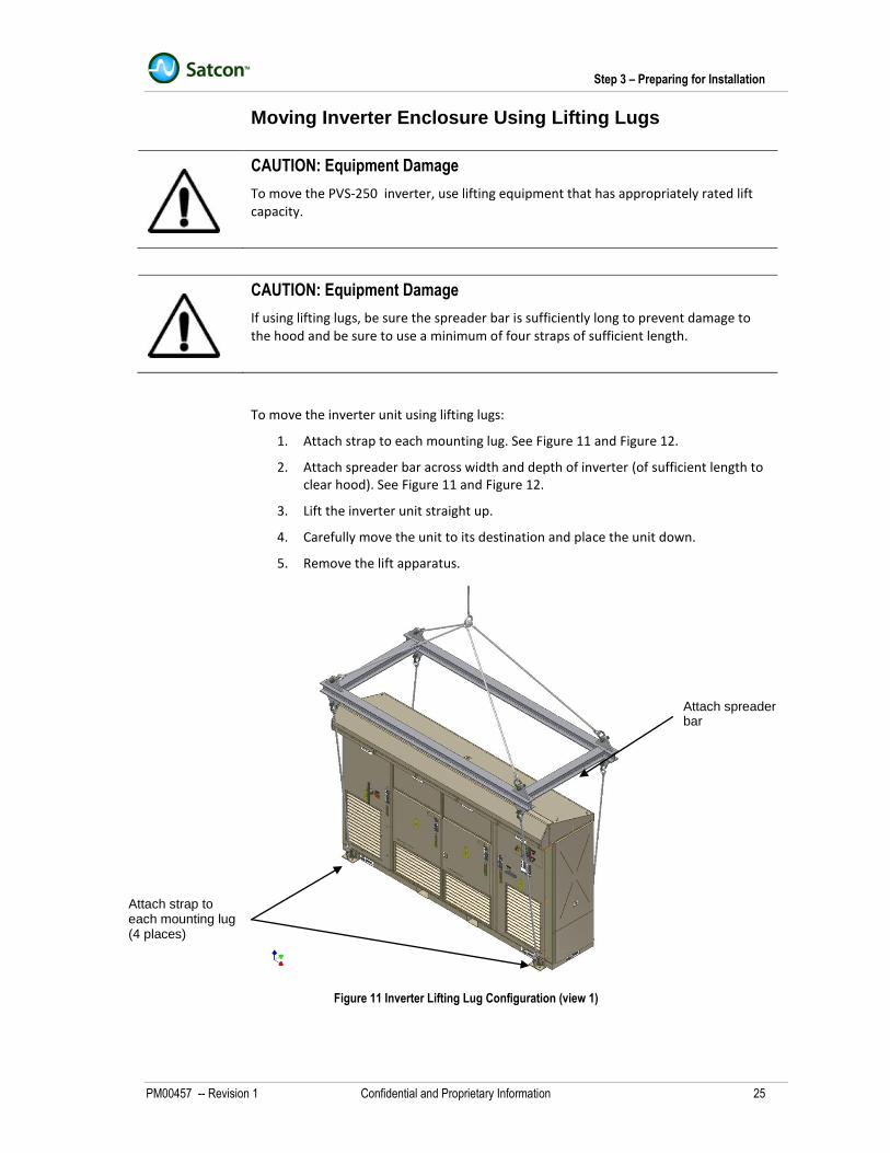
Moving Inverter Enclosure Using Lifting Lugs ................................................................................................................................. 25
Unpacking and Inspecting Inverter Unit .......................................................................................................................................... 26
Step 6 – Connecting Power Conductors .............................................................................................................................................. 29
Identifying Conductor and Wiring Locations ................................................................................................................................... 29
Wiring and Cabling Data ................................................................................................................................................................. 30
Connecting DC Ground ................................................................................................................................................................... 31
Connecting DC Ground Fault Detector/Interrupter ......................................................................................................................... 32
Standard GFDI Configuration ................................................................................................................................................... 32
Connecting AC Ground ................................................................................................................................................................... 33
Connecting DC Input Power ............................................................................................................................................................ 34
Connecting AC Output Power ......................................................................................................................................................... 36
Step 8- Installing Communication and Control Wiring ......................................................................................................................... 37
Types of Communication and Control Wiring.................................................................................................................................. 37
Modbus RTU Serial Communication ........................................................................................................................................ 38
Modbus TCP/IP Communication (Remote Monitoring Option) ................................................................................................. 39
Wiring RS-485 Serial Communications Link ................................................................................................................................... 42
Wiring for ModbusTCP/IP Network (Remote Monitoring Option).................................................................................................... 43
Wiring Remote Inverter Control ....................................................................................................................................................... 44
Chapter 3 Operations Information ................................................................................................................................... 47
About this Chapter ............................................................................................................................................................................... 47
Overview of Operations ........................................................................................................................................................................ 48
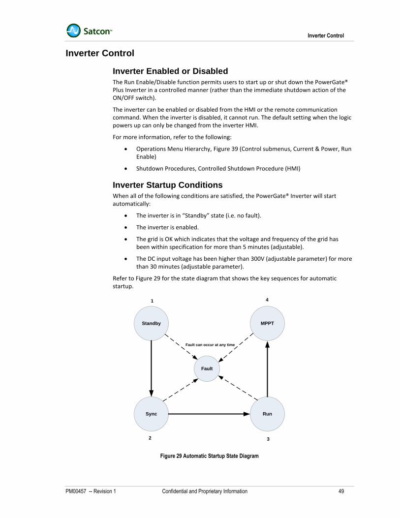
Operating States .................................................................................................................................................................................. 48
Inverter Control .................................................................................................................................................................................... 49
Inverter Enabled or Disabled .......................................................................................................................................................... 49
Inverter ON/OFF Control ................................................................................................................................................................. 51
Maximum Power Point Tracking .......................................................................................................................................................... 52
Local and Remote Control ................................................................................................................................................................... 53
Data Flow between PC and Inverter ............................................................................................................................................... 53
AC Output Reactive Power Control...................................................................................................................................................... 59
Fan Control........................................................................................................................................................................................... 59
About the Keypad and Display ............................................................................................................................................................. 63
About the Menu Structure .................................................................................................................................................................... 64
Using Keypad and Display ................................................................................................................................................................... 66
How to Move to Lower Level ........................................................................................................................................................... 66
How to Move Up One Level ............................................................................................................................................................ 66
How to Enter and Save Data (Operation Sub Menus Only) ........................................................................................................... 66
How to Clear Faults ......................................................................................................................................................................... 66
How to View Faults ......................................................................................................................................................................... 66
Menu Descriptions ............................................................................................................................................................................... 70
Monitoring Menu Descriptions ........................................................................................................................................................ 70
Status Submenu Descriptions .................................................................................................................................................. 70
Firmware Sub Menu Descriptions ............................................................................................................................................. 70
Metering Sub Menu Descriptions .............................................................................................................................................. 71
Energy Production Sub Menus ................................................................................................................................................. 73
System Information Sub Menus ................................................................................................................................................ 73
Status and Faults Menu .................................................................................................................................................................. 74
Operations Menu ............................................................................................................................................................................. 75
Control Submenus .................................................................................................................................................................... 75
Field Adjustment Set Points ................................................................................................................................................................. 82
Front Matter
v
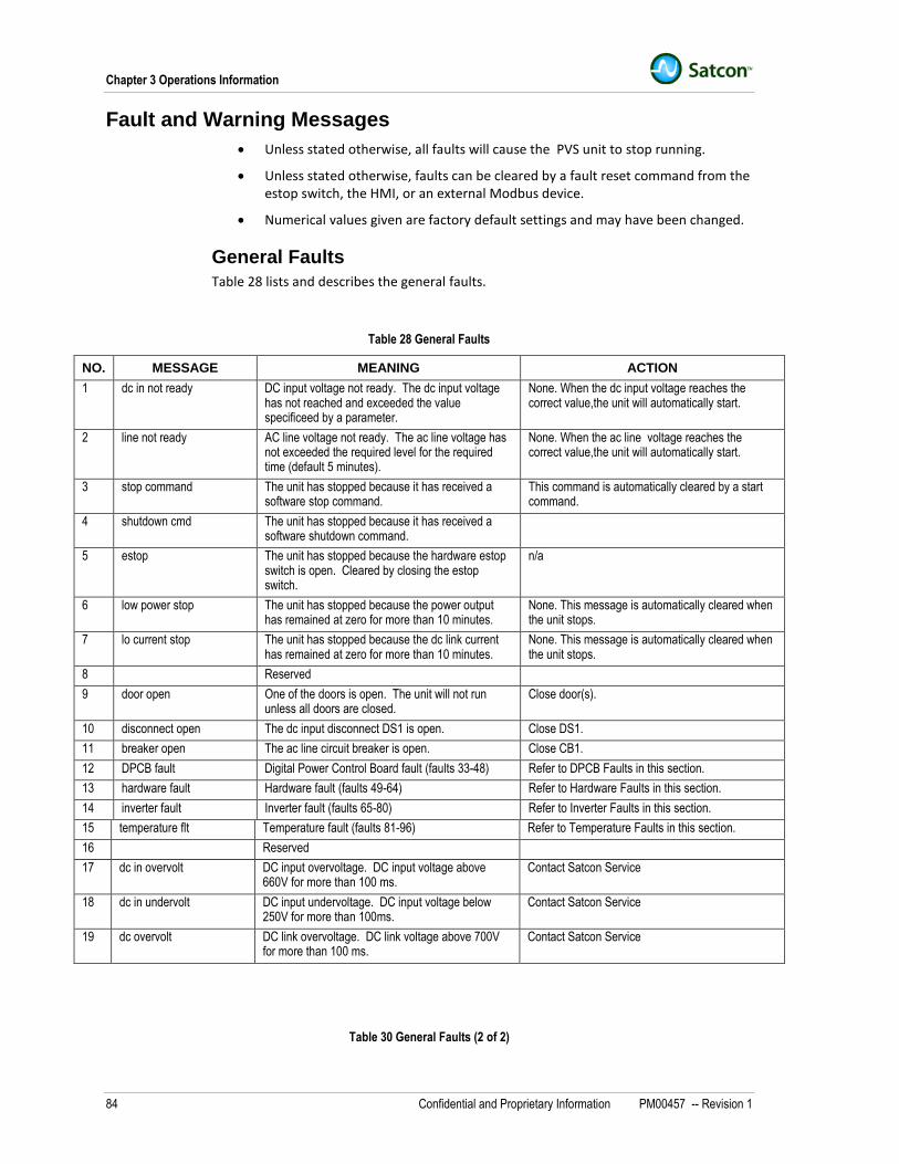
Fault and Warning Messages .............................................................................................................................................................. 84
General Faults ................................................................................................................................................................................. 84
Temperature faults .......................................................................................................................................................................... 88
Chapter 4 Maintenance Information ............................................................................................................................... 93
About this Chapter ................................................................................................................................................................................ 93
About Warranty and Preventive Maintenance...................................................................................................................................... 94
Standard Warranty .................................................................................................................................................................... 94
Preventive Maintenance under Standard Warranty ............................................................................................................................. 96
Guidelines for Cleaning and General Inspection ............................................................................................................................ 98
Guidelines for Cable Maintenance .................................................................................................................................................. 99
Guidelines for Power Component Maintenance ............................................................................................................................. 99
Guidelines for Printed Circuit Board Maintenence .......................................................................................................................... 99
Guidelines for Blower Fan Maintenence ....................................................................................................................................... 100
Guidelines for Air Filter Maintenence ............................................................................................................................................ 100
General Maintenance Workmanship ............................................................................................................................................. 100
About this Chapter .............................................................................................................................................................................. 101
Connecting AC and DC Power Cables .............................................................................................................................................. 102
Initial Power Up .................................................................................................................................................................................. 102
Figure 1 PV View Plus Remote Monitoring Option ..................................................................................................................................... 4 Figure 2 PVS-250 Model ........................................................................................................................................................................... 10 Figure 3 Enclosure Door Latch ................................................................................................................................................................. 11 Figure 4 Human Machine Interface (HMI) ................................................................................................................................................ 15 Figure 5 Enclosure Mounting Dimensions (PVS-250 Model) ................................................................................................................... 20 Figure 6 Planning for Cable and Wiring Entries (Left Side Access) ......................................................................................................... 21 Figure 7 Planning for Cable and Wiring Entries (Rear Access) ................................................................................................................ 21 Figure 8 Planning for Cable and Wiring Entries (Bottom Access) ............................................................................................................ 22 Figure 9 Ground to Gland Plate Clearance (PVS-250 Model) .................................................................................................................. 22 Figure 10 Lifting Enclosure Using Forklift ................................................................................................................................................. 24 Figure 11 Inverter Lifting Lug Configuration (view 1) ................................................................................................................................ 25 Figure 12 Inverter Lifting Lug Configuration (view 2) ................................................................................................................................ 26 Figure 13 Enclosure Internal Locations (PVS-250 Model)........................................................................................................................ 29 Figure 14 Enclosure Safety Ground and DC Ground (PVS-250 Model) .................................................................................................. 31 Figure 15 AC Ground (PVS-250 Model) ................................................................................................................................................... 33 Figure 16 DC Input Connections (No Combiner, Negative Ground) ........................................................................................................ 34 Figure 17 DC Input Connections (No Combiner, Positive Ground) .......................................................................................................... 35 Figure 18 DC Input Connections (Combiner Option) ................................................................................................................................ 35 Figure 19 AC Output Connections (PVS-250 Model) ............................................................................................................................... 36 Figure 20 Control and Communication Wiring Location ........................................................................................................................... 37 Figure 21 Control and Communication Connections ................................................................................................................................ 37 Figure 22 Understanding Modbus Serial Wiring ....................................................................................................................................... 38 Figure 23 RS-485SS Simplified Schematic (Modbus RTU)...................................................................................................................... 39 Figure 24 Understanding Remote Monitoring Option Wiring .................................................................................................................... 40 Figure 25 Remote Wiring Option (Simplified Wiring Diagram) ................................................................................................................. 41 Figure 26 RS485SS Wiring Information .................................................................................................................................................... 42 Figure 27 Remote Monitoring Option Wiring ............................................................................................................................................ 43 Figure 28 TBC Control Wiring Information ................................................................................................................................................ 44 Figure 29 Automatic Startup State Diagram ............................................................................................................................................. 49 Figure 30 State Diagram for Inverter Shutdown ....................................................................................................................................... 50 Figure 31 AC Output Reactive Power Control, PVS-250 Model ............................................................................................................... 59 Figure 32 UL1741 Table for Maximum Ground Currents ......................................................................................................................... 60 Figure 33 UL1741 Time Delay for Opening Ground Path......................................................................................................................... 61 Figure 34 EGFDI Connections .................................................................................................................................................................. 62 Figure 35 HMI Display .............................................................................................................................................................................. 63 Figure 36 HMI Menu Hierarchy ................................................................................................................................................................. 64 Figure 37 Monitoring Menu Hierarchy....................................................................................................................................................... 67 Figure 38 Status and Faults Menu Hierarchy ........................................................................................................................................... 68 Figure 39 Operations Menu Hierarchy ...................................................................................................................................................... 69
Front Matter
vii
List of Tables
Table 1 Ratings and Specifications for PVS-250 Model (1 of 2) ................................................................................................................. 8 Table 2 Physical Data for 250kW Model ................................................................................................................................................... 13 Table 3 Wire and Cable Connection Details for PVS-250 Model ............................................................................................................. 30 Table 4 Inverter Operating States ............................................................................................................................................................. 48 Table 5 Modbus Registers for Fault Parameters ...................................................................................................................................... 54 Table 6 Modbus Registers for Metering Parameters ................................................................................................................................ 54 Table 7 Modbus Registers for String Current Parameters ........................................................................................................................ 55 Table 8 Modbus Registers for String kW Hour Parameters ...................................................................................................................... 56 Table 9 Modbus Registers for Energy Parameters ................................................................................................................................... 57 Table 10 Modbus Registers for Line Feedback Parameters .................................................................................................................... 57 Table 11 Modbus Registers for Fault Queue Parameters ........................................................................................................................ 57 Table 12 Modbus Registers for Input/Output Parameters ........................................................................................................................ 57 Table 13 Modbus Registers for Temperature Feedback Parameters ....................................................................................................... 58 Table 14 Modbus Registers for Serial Number Parameters ..................................................................................................................... 58 Table 15 Modbus Registers for Components Parameters ........................................................................................................................ 58 Table 16 Modbus Registers for Writeable Parameters ............................................................................................................................. 58 Table 17 Menu Summary .......................................................................................................................................................................... 65 Table 18 Status Submenu Descriptions .................................................................................................................................................... 70 Table 19 Firmware Submenu Descriptions ............................................................................................................................................... 70 Table 20 Metering Submenu Descriptions (1 of 2) ................................................................................................................................... 71 Table 21 Energy Production Submenu Descriptions ................................................................................................................................ 73 Table 22 System Information Submenu Descriptions ............................................................................................................................... 73 Table 23 Status and Faults Submenu Descriptions .................................................................................................................................. 74 Table 24 Control Submenu Descriptions (1 of 5) ...................................................................................................................................... 75 Table 25 Settings Submenu Descriptions (1 of 2) .................................................................................................................................... 80 Table 26 Default Trip Level Settings to Shutdown Inverter ...................................................................................................................... 82 Table 27 Trip Level Settings to Stop Inverter ............................................................................................................................................ 83 Table 28 General Faults............................................................................................................................................................................ 84 Table 29 DPCB Faults .............................................................................................................................................................................. 86 Table 30 Hardware Faults ......................................................................................................................................................................... 87 Table 31 Inverter Faults ............................................................................................................................................................................ 88 Table 32 Temperature Faults .................................................................................................................................................................... 88 Table 33 Warning Messages .................................................................................................................................................................... 89 Table 34 Semi-Annual maintenance Service Tasks ................................................................................................................................. 97 Table 35 Annual Maintenance Service Tasks ........................................................................................................................................... 97
Front Matter
viii
About This Guide
Purpose
This manual provides information about installing, operating, maintaining, and troubleshooting the PVS-250 PowerGate ® PLUS inverters.
Who Should Read this Manual
This manual is intended for customers who must install, operate and maintain these inverters.
How the Manual is Organized
This manual is divided into two primary sections: front matter (section 1) and five chapters (second section).
Section 1:
Front Matter: This section contains important safety information, together with information about the conventions used in this manual as well as a listing of the symbols used in the equipment.
Section 2:
Chapter 1 Product Information: This chapter provides general information about PowerGate ® PLUS Inverters, including their important features, ratings and specifications, physical descriptions, and user controls.
Chapter 2 Installation Information: This chapter provides information to help plan the installation, how the enclosure should be mounted, and how it should be connected electrically.
Chapter 3 Operations Information: This chapter provides information about the inverter operations, including its different operating states and how the user can interact with the unit.
Chapter 4 Maintenance Information: This chapter provides information about scheduled and periodic maintenance.
Chapter 5 Commissioning Procedures: Explains how to start up the inverter after installation
Reference Manuals
If you need additional information about the PowerGate® Plus options or communication interfaces, refer to the following user manuals:
PM00440- PV View® Plus User Guide
PM00443- PV View® Plus XML Interface Guide
PM00445- PV View® Plus XML Utility Guide
PM00452-PV Modbus RTU Communication Interface Reference Guide
PM00454-PV TCP/IP Communication Interface Reference Guide
PM00447-PV View® Plus Weather Station
Front Matter
ix
Conventions Used
WARNING
Warnings tell you about conditions and actions that could result in personal injury or death. A qualifier (e.g. Hazardous Voltage) may follow the warning title.
CAUTION
Cautions tell you about conditions or actions that could result in damage to the inverter or other equipment. A qualifier (e.g. Inverter Damage) may follow the warning title.
NOTE
Notes tell you about things which are important for you to know but not as serious as cautions or warnings.
Front Matter
x
IMPORTANT SAFETY INSTUCTIONS
SAVE THESE INSTRUCTIONS This manual contains important instructions for the PVS-250 that shall be followed during installation and maintenance of the inverter.
WARNING
The PowerGate ® PLUS Inverter system presents a SHOCK HAZARD. Read and keep this Operation and Maintenance Guide for future reference. Before installing the PVS-50, read all instructions, cautionary markings and other appropriate sections of this guide. Failure to follow these warnings could result in severe shock or even death. Exercise extreme caution at all times to prevent possible accidents.
WARNING
These instructions are not meant to cover every safety eventuality nor to replace any local or site specific safety procedures. The information in this section is intended as a supplement to local or site specific procedures. Satcon does not assume responsibility for the compliance or noncompliance to any code, national, local or otherwise for the proper installation of the PowerGate ® PLUS Inverter or associated equipment supplied.
A potential for personal injury and/or equipment damage exists if electrical codes and these instructions are not followed.
DANGER
This PowerGate® PLUS Inverter contains LETHAL VOLTAGES. Authorized service personnel only should perform all repairs and service. There are no user serviceable parts inside this inverter.
Front Matter
xi
General Safety Precautions
WARNING
Only qualified personnel familiar with the PowerGate ® PLUS Inverter design should plan or implement the installation, start-up and subsequent maintenance of the system. Failure to comply may result with personal injury and or equipment damage.
WARNING
An incorrectly installed PowerGate ® PLUS inverter may result in equipment damage or a reduction in product life. Incorrect wire sizing, inadequate supply, or excessive ambient temperatures may result in system malfunction.
CAUTION
This PowerGate ® PLUS Inverter contains ESD (Electrostatic Discharge) sensitive parts and assemblies. Static control precautions are required when installing, testing, servicing or repairing this unit. Board component damage may result if proper ESD measures are not followed.
WARNING
To avoid an electric shock, verify that the voltage on the bus capacitors has discharged before performing any work on the PowerGate ® PLUS Inverter. Measure the voltage across CF (wires 14 and 15) in the inverter; this voltage must be zero to be fully discharged.
WARNING
The enclosure contains exposed high voltage conductors. The enclosure door should remain locked, except during maintenance or testing by trained service personnel. Do not open the cabinet doors if extreme moisture is present (rain, snow or heavy dew).
Front Matter
xii
Electrical Safety Precautions and Practices
WARNING
ELECTRIC SHOCK can KILL. Do not touch live electrical parts. ELECTRIC ARC FLASH can injure eyes, burn skin, cause equipment damage and ignite combustible material. DO NOT disconnect load power by disconnecting power cables. Prevent tools from causing short circuits.
Be aware that you do not have to physically touch high-voltage parts to receive an electrical shock; high-voltage can jump across gaps seeking objects of lower potential (i.e. body parts, tools, or equipment).
Safe Practices
Equipment that supplies electrical power can cause serious injury or death, or damage to other equipment or property. The operator must strictly observe all safety rules and take precautionary actions. Safe practices have been developed from past experience in the use of power source equipment.
Shock Prevention
Bare conductors, terminals in the output circuit or ungrounded, electrically live equipment can fatally shock a person. Be sure to follow the following guidelines:
Have a certified electrician verify that the equipment is adequately installed and grounded.
Only authorized and properly trained personnel should maintain or troubleshoot the PowerGate ® PLUS Inverter.
Use proper safety clothing, procedures and test equipment.
The electrical resistance of the body is decreased when wet, permitting dangerous currents to flow through it. While inspecting or servicing equipment, do not work in damp areas.
Stand on a dry rubber mat or dry wood, and use insulating gloves when dampness or sweat cannot be avoided and never work alone.
The equipment must be installed and maintained in accordance with the National Electrical Code NFPA 70, or other applicable codes.
Inspect cables frequently for damage to the insulation and the connectors. Replace or repair cracked or worn cables immediately.
Do not overload cables.
Do not touch output terminal while equipment is energized.
WARNING
DC input terminals and output terminals remain energized when internal disconnects and breakers are open. .
Front Matter
xiii
Service and Maintenance
This equipment must be maintained in good electrical condition to avoid hazards stemming from disrepair. Report any equipment defect or safety hazard to the supervisor and discontinue use of the equipment until its safety has been assured. Only qualified personnel should make repairs to the inverter.
Before servicing, disconnect AC and DC sources to the inverter.
WARNING
The PowerGate ® PLUS Inverter contains high-voltage DC capacitors. Allow five (5) minutes for all capacitors within the enclosure to discharge after disconnecting the inverter from AC and DC sources.
Fire and Explosion Prevention
Fire and explosion are caused by electrical short circuits, combustible material near the equipment, or unsafe operating conditions. Overloaded or shorted equipment can become hot enough to cause fires by self-destruction or by causing nearby combustibles to ignite. Provide primary input protection to remove short circuited or heavily overloaded equipment from the line.
Bodily Injury Prevention
Serious injury can result from contact with live circuit components inside this equipment, SHUT down this equipment for inspection and routine maintenance in accordance with “Chapter 3 Operations Information, Shutdown Procedures”. When equipment is in operation, use extreme care in doing necessary troubleshooting and adjustment.
Medical and First Aid Treatment
First aid procedures need to be in place in accordance with local and site health and safety procedures. Electric shock victims should be checked by a physician and taken to hospital immediately if any abnormal signs are observed.
Equipment Precautionary/Warning Labels
Inspect all precautionary, warning labels on the equipment monthly. Order and replace all labels that cannot be easily read or are worn out. Labels can be ordered by email at [email protected].
Potential Equipment Damage
Improper phase connection, paralleling, or use can damage the equipment. Maintenance personnel should become familiar with the layout and be aware of the basic system parameters. Only qualified trained personnel should be allowed to work with this equipment under competent supervision. The DC input voltage present for the solar array can be as high as 660VDC (maximum). The AC output voltage can be as high as 600VAC depending on output configuration and utility voltage.
PowerGate ® PLUS Inverters contain the following integrated electrical safety features:
Software protection controls (described in “Chapter 3 Operations Information”).
Enclosure Door Interlock Switches (described in “Chapter 1 Product Information and Chapter 3 Operations Information”).
ON/OFF switch (described in “Chapter 1 Product Information and Chapter 3 Operations Information”)
DC Disconnect Switch (described in “Chapter 1 Product Information and Chapter 3 Operations Information”)
AC Disconnect switch or AC circuit breaker (described in “Chapter 1 Product Information and Chapter 3 Operations Information”)
Anti-islanding protection (described in “Chapter 1 Product Information”)
Be sure to understand these features.
Front Matter
xv
Handling Safety
When moving the enclosure, handle with care and caution.
CAUTION
Do not use the hold-down brackets for lifting. Unit must be lifted from the bottom. Unit must be supported on all four sides when lifting due to its narrow width and depth.
CAUTION
Ensure that the load rating of the lifting device is sufficient to safely lift the electrical unit.
Front Matter
xvi
Special Symbols
The following special symbols are used within the PowerGate® PLUS Inverter enclosure
GROUND – Symbol used throughout the enclosure to designate a connection point to ground.
DC Positive – Symbol used throughout the enclosure designate a connection point to the DC Positive of the Solar Photovoltaic Array.
DC Negative – Symbol used throughout the enclosure to designate a connection point to the DC Negative of the Solar Phortovoltaic Array.
AC Circuit – Symbol used throughout the enclosure to designate that a circuit is an AC, 60Hz circuit.
Number of Phases– Symbol used throughout the enclosure to indicate the number of the phases in the circuit
ON position– Symbol used throughout the enclosure to indicate the ON position of switches and breakers.
OFF position– Symbol used throughout the enclosure to indicate the OFF position for switches and breakers.
DC Circuit – Symbol throughout the enclosure designates the circuit intended to be connected to a DC circuit
Chapter 1 Product Information
PM00457 -- Revision 1 Confidential and Proprietary Information 1
Chapter 1 Product Information
About this Chapter
This chapter introduces the PVS-250 PowerGate® PLUS inverter. Topics include:
Technologies and design features
Operational features
Safety features
Ratings and specifications
Physical description
Operator controls
Chapter 1 Product Information
2 Confidential and Proprietary Information PM00457 -- Revision 1
Overview
The PVS-250 PowerGate ® PLUS inverter is a power conversion system that is designed to be used in grid-connected photovoltaic systems. These types of systems represent one of the most important configurations of distributed energy resources (DER).
The PVS-250 has a power rating of 250kW. The unit is easy to install, easy to operate, and incorporates the latest technologies.
Regulatory Standards
The PVS-250 PowerGate ® PLUS inverters are fully certified to the following standards:
“Standard for Inverters, Converters, Controllers and Interconnection System Equipment for Use With Distributed Energy Resources,” UL1741, including revisions through and including November , 2005
“General Use Power Supplies,” CSA 107.1
PowerGate ® PLUS inverters also comply with IEEE 1547, including testing to IEEE 1547.1 and IEEE C62.45.
Technologies and Design Features
The PowerGate® PLUS inverters convert the DC outputs of photovoltaic arrays into three phase AC power using reliable, high efficiency Insulated Gate Bipolar Transistors (IBGT) as the primary switching devices. These devices are rated for 1200V and operate at very high switching frequencies. The inverter itself makes use of a snuberless design, meaning that there are no resistive-capacitive (RC) circuits that can reduce efficiency as well as reliability.
Design features include:
The unit is designed solely for connection to the grid, namely “Line Linkage Mode” (Grid Export Mode), where it exports power to the grid when the DC output from solar photovoltaic array is available.
The power is exported to the grid (Grid Export Mode) by the inverter in AC Current Control mode whereby the current in each phase of the three phase inverter is precisely controlled by the inverter regulator.
The three phases output voltages and currents are sinusoidal with low total harmonic distortion to meet the UL1741 and IEEE 519-1992 harmonic requirements.
The control circuit uses a digital control board named “Digital Power Control Board” (DPCB) using digital signal processor (DSP) and Field Programmable Gate Array (FPGA) chips for control, system monitoring and protection.
Many areas and components sensitive to over-temperature conditions are monitored with thermal detectors. Extensive electronic fault detection schemes, with fuses are employed to ensure safety of critical circuits.
Isolation Transformer
All PowerGate® PLUS Inverters include a high-efficiency Delta/Wye isolation transformer that has very low coil and core losses. This transformer is mounted within the inverter enclosure where it performs two functions.
First, it provides galvanic isolation when the solar array is grounded.
Operational Features
PM00457 -- Revision 1 Confidential and Proprietary Information 3
Second, it allows the inverter to match the voltage of the utility grid. The utility side windings of the inverter are configured Wye and must match the voltage at the utility inter-tie during installation.
The isolation transformer also has a tap on the low voltage side to enable the inverter to operate when the incoming PV array voltage drops below 305VDC.
The isolation transformer is a dry type transformer wound with high-temperature insulation. The unit is vacuum pressure impregnated (VPI) with polyester resin for durability and protection against the environment. The transformer is forced air cooled by ambient air and designed with a 1.10 service factor for long life. The unit includes over-temperature switches for protection and indication on the panel display of the PowerGate® PLUS Inverter.
Operational Features
Maximum Power Point Tracking
The PV array has a unique operating point (voltage-current curve) at which it can supply maximum power. This point is called the maximum power point (MPP). However this point changes continuously with the unpredictable variations in solar irradiance and cell temperatures.
Maximum Power Point Tracking (MPPT) is a method to operate the PV array in a way that allows it to deliver its maximum power more efficiently at every instant.
To do this, the PowerGate® PLUS inverters use a sophisticated algorithm to continuously seek the optimum voltage and current operating points of the PV array. The optimum settings are controlled through the Human Machine Interface (HMI) parameters entered through the keypad and display.
Unity Power Factor
The PowerGate® PLUS Inverter continuously senses the utility voltage and frequency and adjusts its output current waveform to match the utility voltage.
Remote Monitoring Option
The PowerGate® PLUS inverter may be equipped with either the Satcon PV View™ Plus option (Figure 1) or other third-party web-enabled data monitoring option.
With the remote monitoring option, the PowerGate ® Plus inverter allows parameters (DC voltage and current, AC voltage and current, and power) to be transmitted over a Modbus communication link to a Gateway so that these parameters can be viewed in real-time via the internet (website). Data can then be accessed through secure servers by various State and/or Utility photovoltaic programs.
Refer to the Satcon PV View® Plus or third-party web-enabled data monitoring option manual for more information.
Chapter 1 Product Information
4 Confidential and Proprietary Information PM00457 -- Revision 1
Figure 1 PV View Plus Remote Monitoring Option
Safety Features
PM00457 -- Revision 1 Confidential and Proprietary Information 5
Safety Features
PowerGate® PLUS inverters have both hardware and software safety features to suit different purposes and actions. This section describes these features.
Enclosure Door Interlock Switch
The door interlock switch is provided to prevent operation while the front door is opened (for maintenance and servicing). When a door is opened, the PowerGate® PLUS Inverter immediately starts a controlled shutdown of the unit (opens the main AC and DC contactors in a controlled sequence). These contactors cannot be closed until the door interlock switch is in the engaged position.
WARNING
The door interlock switch turns off power being delivered by the inverter. However, live power will exist in both the DC and AC sections within the enclosure. Exercise extreme care when servicing or maintaining the equipment.
DC Disconnect Switch
To make maintenance work safer, all PowerGate® PLUS inverters have a DC switch (DS1) that isolates both poles of the solar array panels from the inverter. This switch, which includes an electrical interlock, is also used as a no-load disconnecting device.
NOTE
Local electrical code may require a full load disconnect switch be accessible at all times for the user. In some cases, an additional DC disconnect switch may be required externally for compliance to some local codes. Consult local load authorities for more information.
AC Circuit Breaker
The PVS-250 Model is equipped with an AC circuit breaker to isolate the inverter from the grid.
ON/OFF Switch
The PowerGate® PLUS Inverter unit has an ON/OFF switch, located on the operator interface panel on the main door. When this switch is turned to its OFF position, the inverter immediately shuts down.
Chapter 1 Product Information
6 Confidential and Proprietary Information PM00457 -- Revision 1
WARNING
The ON/OFF switch turns off power being delivered by the inverter. However, live power will exist in both the DC and AC sections within the enclosure
Over Voltage and Over Current Detection
Over voltage and over current are controlled by internal control electronics and associated software. If the trip set points are exceeded, the inverter will shutdown in an orderly manner.
Ground-Fault Detection and Interruption Configurations
The PowerGate® Plus Inverter can be equipped with either fuse ground-fault detection and circuit interruption (GFDI option) or electronic ground-fault detection and circuit interruption (EGFDI option). The inverter cannot be equipped with both.
Standard Configuration (GDFI Option)
The GDFI option is standard on all PowerGate® PLUS Inverters.
With the standard configuration, ground fault protection is provided by a fuse (FUGFDI).
A current sensor is also provided to measure operating ground current. The auxiliary contact of the ground fuse is monitored. If a ground fault occurs and the fuse opens, the PowerGate ® PLUS inverter shuts down immediately by opening all AC and DC contactors. This in turn isolates the inverter from the grid. The GDFI configuration complies with NEC 690.5.
Optional Configuration (EGFDI Option)
The EGFDI (Ground Fault Detector Interrupter) is a solid-state electronic ground fault detector and interrupter designed to provide DC fault protection of the solar photovoltaic array when the array’s positive or negative pole has to be grounded. The EGFDI is designed to fulfill the requirements of Section 31 of UL1741 “Inverters, Converters, Controllers and Interconnection System Equipment for Use with Distributed Energy Resources”.
Refer to “Chapter 3 Operations Information”, Electronic Ground Fault Detector Interrupter Operation” for more information.
Anti-Islanding Protection
PowerGate® PLUS Inverters meet the stringent requirements of UL 1741 “Inverters, Converters, Controllers and Interconnection System Equipment for Use with Distributed Energy Resources”. UL 1741 is a standard that specifies the anti-islanding protection criteria for all distributed generation solutions.
Electrical system islanding occurs when the utility grid is removed but local energy sources, such as photovoltaic inverters, continue to operate and supply power to local loads.
Unintentional islanding is an unwanted condition that can pose a shock hazard to line crew as well as damage to electric equipment.
Safety Features
PM00457 -- Revision 1 Confidential and Proprietary Information 7
Photovoltaic inverters monitor frequency and voltage to detect grid outages. If the grid goes down, the frequency and voltage values in the isolated section —the section containing the inverter—change from their previous values, and the inverter will disconnect itself from the load. However, if the local load starts resonating at the same frequency as the grid frequency, the inverter assumes that the grid is still operational and will continue to supply power (a condition called islanding). Therefore, monitoring frequency and voltage values alone will not prevent islanding.
PowerGate® PLUS Inverters use additional techniques to ensure islanding does not occur.
First, the inverter changes the resonant frequency of the load slightly so that the operating frequency will move out of tolerance. This change, created by a very small swing of virtual reactance from the inverter to the load, is extremely slight and does not affect the line frequency when the grid is connected. However, if the utility grid is disconnected, the resonant frequency of the load changes because of virtual reactance applied by the inverter. The resulting change in the load frequency is immediately detected by the inverter’s logic system.
In addition to the applied virtual reactance, the inverter uses a sophisticated algorithm to ensure that the anti-islanding trip disconnect occurs within the times specified by UL1741. Refer to “Chapter 3 Operations Information, Electronic Ground Fault Detector Interrupter Operation”.
Chapter 1 Product Information
8 Confidential and Proprietary Information PM00457 -- Revision 1
Ratings and Specifications
Table 1 provides detailed information about ratings and specifications of the PowerGate® PLUS inverters.
Table 1 Ratings and Specifications for PVS-250 Model (1 of 2)
250kW/250kVA PowerGate® PLUS Inverter RATINGS/SPECIFICATIONS
208/240VAC 480VAC
1 ELECTRICAL
Input Parameters
Input Voltage Maximum (from solar array) 600VDC
Input Voltage Range 322-600VDC 320-600VDC
Input Current Maximum 809ADC / 814ADC
Input Current Range 0-809ADC 0-814ADC
Input Current Maximum Short Circuit (software protection) 1000ADC
Input Source Backfeed Current Maximum 0A
Output Parameters
Number of Phases 3
Output Voltage Range (L-L) 183-229VAC/211-264VAC 422—528VAC
Output Frequency Range 59.3—60.5Hz
Output Nominal Voltage 208VAC/240VAC 480VAC
Output Normal Frequency 60Hz
Maximum Continuous Output Current Per phase 694A/602A 301A
Maximum Output Over-current Protection Per phase (software) 833A/723A 362A
Short Circuit Interrupt Rating (kAIC) 100kA rms 35kA rms
Maximum Continuous Output Power 250KW/250KVA
CEC Weighted Efficiency 96%
Maximum Efficiency 96.5% / 96.6% 96.6%
Tare Losses Max 125W
Power Factor at Full Load >0.99
Adjustable Power Factor From 0.8 lagging to 0.8 leading
Output Current Harmonics THD<3%
Regulatory Standards Meets UL1741, IEEE 1547, including IEEE C62.41.2 and CSA
107.1-01.1:
2 ENVIRONMENT
Operating Ambient Temperature -20 degree C to +50 degree C
Shipping Temperature Range -30 degree C to +70 degree C
Relative Humidity 15%—90% Non-condensing
Sound Level (measured at 1 m) 68.5 dB
Ratings and Specifications
PM00457 -- Revision 1 Confidential and Proprietary Information 9
Table 1 Ratings and Specifications for 250kW Model (2 of 2)
250kW/250kVA PowerGate® PLUS Inverter RATINGS/SPECIFICATIONS
3 PHYSICAL
Location (inverter unit) Indoor/Outdoor
Enclosure (inverter unit) NEMA 3R with environmentally enclosed electronics
Seismic Rating – Zone 4
Maximum Dimensions (Inverter Enclosure). See Table 2. 89.2‖ H x 115.1‖ W x 38.2‖ D (2265mm x 2923 mm x 971 mm)
Weight (Inverter/Transformer) approximate 5700 lbs (2586 kg)
Cooling Forced air (one fan in unit; fan has one backward curved AC
impeller fan)
4 SIGNAL TRANSFER Modbus protocol on RS485 communication link
Hardwired inverter operation and PCS Fault Indication
5 ISOLATION Input No Load Disconnect Switch
Input DC Contactor
Inverter Fuses
AC Contactor
AC Interconnection Breaker
6 OPERATORS Power Generation Light (Red)
ON/OFF Switch
Keypad and Display
Located on outside of main door
7 METERING and SYSTEM STATUS via VFD DISPLAY at HMI Output AC Voltage (all three phases)
Output Current (all three phases)
Real Output Power (kW)
Reactive Output Power (kVAR)
Power Factor
KW-hour
Neutral Current
PV DC Voltage
PV DC Current
PV Power (kW)
DC Bus Voltage
Stop/Run Status
Fault/No Fault Status
Local/Remote Status
Chapter 1 Product Information
10 Confidential and Proprietary Information PM00457 -- Revision 1
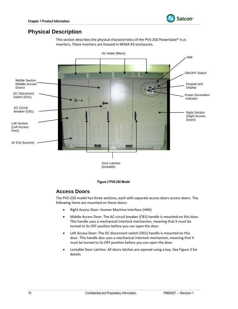
Physical Description
This section describes the physical characteristics of the PVS-250 PowerGate® PLUS
inverters. These inverters are housed in NEMA R3 enclosures.
Figure 2 PVS-250 Model
Access Doors
The PVS-250 model has three sections, each with separate access doors access doors. The following items are mounted on these doors:
Right Access Door: Human Machine Interface (HMI)
Middle Access Door: The AC circuit breaker (CB1) handle is mounted on this door. This handle uses a mechanical interlock mechanism, meaning that it must be turned to its OFF position before you can open the door.
Left Access Door: The DC disconnect switch (DS1) handle is mounted on this door. This handle also uses a mechanical interlock mechanism, meaning that it must be turned to its OFF position before you can open the door.
Lockable Door Latches: All doors latches are opened using a key. See Figure 3 for details.
Door Latches (lockable)
Power Generation Indicator
DC Disconnect Switch (DS1)
AC Circuit Breaker (CB1)
ON/OFF Switch
HMI
Keypad and Display
Right Section (Right Access Doors)
Left Section (Left Access Door)
Air Exit (louvres)
Air Intake (filters)
Middle Section (Middle Access Doors)
Physical Description
PM00457 -- Revision 1 Confidential and Proprietary Information 11
Figure 3 Enclosure Door Latch
Enclosure Left Section
The left section contains the following:
Solar array input
Utility grid output
Enclosure safety ground
Input and output cable access glands
Communication and control wiring
Solar Array Input
All solar array input power cables and cable strings-if the inverter is equipped with the optional internal combiner-are supplied by the customer.
The DC input power from the solar array is connected to the inverter via bus bars. The inverter is equipped with both positive and negative bus bars
The DC input may be grounded or ungrounded. If grounded, the inverter is configured with either a positive or negative ground (pre-specified by the customer).
The inverter may also be configured with or without an optional internal combiner. The configurations are as follows:
Standard Configuration: This configuration does not include the internal combiner. The inverter can accept up to 15 inputs.
Internal Combiner Option 1: With this configuration, you can connect up to 10 ungrounded solar array strings. Each cable string is connected to the inverter through a fuse. The maximum current in each string must not exceed 160A DC.
Internal Combiner Option 2: With this configuration, you can connect up to 15 ungrounded solar array strings. Each cable string is connected to the inverter through a fuse. The maximum current in each string must not exceed 100A DC.
If the PV array is grounded, the inverter can accept the following:
Grounded DC Conductors: The inverter can accept up to 15 positive or negative grounded DC conductors from the solar array.
Sliding cover for key hole
Key
Unlock, then pull and rotate handle
Chapter 1 Product Information
12 Confidential and Proprietary Information PM00457 -- Revision 1
DC Ground Connections: The inverter can accept up to 15 DC ground connections from the array.
The positive input connections are attached to the DC bus bar, marked +. The negative input connections are attached to the DC bus bar, marked -. The bus bars are also connected to the + and – terminals respectively of DS1.
Refer to Table 3 for full technical specifications.
Utility Grid Output
All AC output power cables are supplied by the customer.
The left section contains the bus bars for connecting the AC output from the inverter to the utility grid.
The 3-phase power output (A,B, and C) is connected to the 3-phase, 60Hz utility from the these bus bars. Separate ground and neutral terminals are also provided. Depending on the model, the following AC output voltages are available:
208 V AC
240V AC
480V AC
The circuitry includes the AC circuit breaker (CB1), which is used to isolate the inverter from the grid.
Enclosure Safety Ground
A separate bus bar is provided for the enclosure safety ground. This bus bar is located at the bottom, inside of the left section.
Cable Access Glands
All power cables and wiring can be routed through the top-left, upper-rear, or bottom floor locations in the left section.
Enclosure Middle Section
The middle section contains the AC circuit breaker (CB1) and isolation transformer.
Enclosure Right Section
The enclosure right section contains the following:
Human Machine Interface (HMI)
Logic Processing Box
Enclosure Cooling Fan
Reactor
Human Machine Interface (HMI)
The Human Machine Interface (HMI) is located on the front door of the right section. This panel includes an ON/OFF switch, keypad and display unit, and power generation indicator (lit, when power is being generated by the inverter).
Physical Description
PM00457 -- Revision 1 Confidential and Proprietary Information 13
Logic Processing Box
Logic processing includes the Digital Power Control Board (DPCB) with embedded software and associated electronic circuits. All of these components are mounted in an environmentally sealed box. This box is located in the enclosure behind the HMI controls.
The DPCB and associated electronics generates the pulse width modulating (PWM) signals for the inverter as well as controlling the logic for the entire unit.
Enclosure Cooling Fan
The cooling fan is located in this section, at the top.
Isolation Transformer
The built-in isolation transformer is located in the right section of the enclosure.
Enclosure Cooling Components
The enclosure uses a filtered forced air cooling system using one “backward” impeller fan. The fan, which is located inside the enclosure (right section), draws air through filters in the enclosure hood. The air flow is directed across all semiconductor and overall system components. This air flow is also directed across the magnetics (e.g. reactors) before exiting through the louvres on the lower sides of the enclosure doors.
The louvres are designed to meet NEM R3 requirements and to prevent the ingress of water and the enclosure hood is angled to ensure water run-off occurs properly.
Mounting Lugs
Mounting lugs are provided at four corners and in the middle (front and rear).
Dimensions and Weights
Table 2 summarizes the dimensions and weight of the PVS-250 model.
Table 2 Physical Data for 250kW Model
DIMENSION/WEIGHT MEASURE
Height 89.2 inch (2265 mm)
Width 115.1inch (2923 mm)
Depth 38.2 inch (971 mm)
Weight 5700 lbs (2586 kg) approximate
Chapter 1 Product Information
14 Confidential and Proprietary Information PM00457 -- Revision 1
Human Machine Interface (HMI)
Users interact with the PVS inverter unit through its Human Machine Interface (HMI). The HMI includes the following operator controls and indicators (see Figure 4):
ON/OFF switch (immediate power shutdown)
Run Enable/Disable (controlled power shutdown and startup)
Power Generation Indicator
Keypad and Display
ON/OFF Switch
Under normal operating conditions, the ON/OFF switch is in the ON position.
When the switch is turned to its OFF position, the PowerGate® Inverter immediately shuts down (immediately opens both the main AC and DC contactors). These contactors cannot be closed until the switch is in the ON position.
WARNING
The ON/OFF switch turns off the inverter. However, live power will exist in both the DC and AC sections within the enclosure
Run Enable/Disable
The Run Enable/Disable permits operators to either startup the inverter or shut it down in a controlled manner (rather than the immediate shutdown action of the ON/OFF switch). Run Enable/Disable is controlled using the HMI (see below).
Power Generation Indicator
The power generation indicator, when lit, visually tells you that power is being generated by the unit.
Keypad and Display
The keypad and display is mounted on the front door of the enclosure (see Figure 4). The keypad and display assembly is completely watertight and is made up of a display and touch-sensitive keypad.
The keypad and display provides an easy and convenient way to control the inverter. For example, you use it to enable or disable MPPT, or change other values. It is also used for troubleshooting purposes (fault messages).
Human Machine Interface (HMI)
PM00457 -- Revision 1 Confidential and Proprietary Information 15
Figure 4 Human Machine Interface (HMI)
Display
The display uses vacuum fluorescent display (VFD) technology. VFD technology is superior to Light Emitting Display (LED) technology because it is more readily visible under bright conditions, such as direct sunlight.
The unit can display up to four lines of alpha-numeric characters and up to 20 characters per line.
Keypad
The keypad is made up of the following touch-sensitive keys:
Refer to “Chapter 3 Operations Information” for information about using this keypad.
Keypad and Display
ON/OFF Switch Power Generation Indicator (RED)
Chapter 1 Product Information
16 Confidential and Proprietary Information PM00457 -- Revision 1
THIS PAGE INTENTIONALLY LEFT BLANK
Chapter 2 Installation Information
PM00457 -- Revision 1 Confidential and Proprietary Information 17
Chapter 2 Installation Information
About this Chapter
This chapter contains the following information:
Planning for installation
Moving and anchoring enclosure(s)
Installing conduits
Making the ground, power input and power output connections
Making remote communications and inverter control wiring
Verifying the installation
Commissioning the unit
This chapter includes information about cable sizes and torque specifications for making cable connections.
Chapter 2 Installation Information
18 Confidential and Proprietary Information PM00457 -- Revision 1
Step 1- Before Starting Installation
This section contains guidelines for the installation process. Use this process to install the inverter:
1. Perform Step 2 - Plan the installation
2. Perform Step 3 – Prepare for installation
3. Perform Step 4 – Mount and anchor unit
4. Perform Step 6 – Install conduits
5. Perform Step 7 – Install power conductors and wiring
6. Perform Step 8 – Install communication and control
7. Perform Step 9 – Verify installation
8. Perform Step 10 – Verify input and output power requirements
9. Perform Step 11 - Commission unit
Step 2 - Planning for Installation
PM00457 -- Revision 1 Confidential and Proprietary Information 19
Step 2 - Planning for Installation
This section contains information to help you plan the installation process. Planning tasks include the following:
1. Allowing enough clearance for inverter ventilation and serviceability
2. Ensuring that the enclosure can be anchored properly
3. Planning the cable routing
WARNING: Shock Hazard
The method of installation, conductor size, and over-current protection must conform to the requirements of the local electrical code or other applicable codes and standards. Only qualified persons shall install the wiring and commission the unit.
Ventilation and Serviceability Requirements
Make sure that the following conditions are met to ensure the safe and efficient operation of the unit, as well as its servicing and maintenance.
Ventilation Requirements
Refer to “Environment” column in Table 1 for the operating ambient temperature and relative humidity specifications for this inverter.
This inverter uses filtered forced air-cooling for all internal cooling. A backward curved impeller fan draws air through the filtered air-intakes located at the top of the inverter unit. Air is forced downwards through the entire enclosure and out through the louvres on the front doors of the unit. The air-exhaust louvres are designed to meet NEMA 3 standards. Refer to the enclosure layout drawing in the appendix.
The resulting air flow cools:
The 3-phase inverter assemblies, which use air-cooled heat sinks for cooling of the IGBT semiconductors.
The magnetics at the bottom of the enclosure, which require a minimum airflow to stay within temperature specifications.
Be sure that the air flow path (from air intake at top to air exhaust at bottom) is not restricted. Any obstructions in the airflow path will degrade the performance of the inverter and can result in nuisance-tripping of the unit (power output shutting off).
Note that this PowerGate® PLUS inverter does not require any clearance at the back or sides of the unit for ventilation requirements.
Serviceability Access Requirements
The PVS-250 PowerGate® PLUS inverter is designed so that they require access only from the front. Check with local codes for any specific requirements.
Chapter 2 Installation Information
20 Confidential and Proprietary Information PM00457 -- Revision 1
Enclosure Anchoring Requirements
The PVS-250 PowerGate® PLUS inverter is designed to be installed in an outdoor location. The unit must be placed on and anchored to a level concrete floor or pad.
The concrete floor or pad must be designed to meet the local requirements for weight, seismic, and wind shear if necessary.
The concrete floor or pad must have pre-installed anchoring bolts. Twelve anchoring bolts will be required.
For seismic 4 rated installation, bolt the unit down using 12 M20 (0.75-inch) minimum diameter bolts with an 11.5 cm (4.5-inch) embedment depth. It is recommended that a HILTI HIT 500 high-performance injection system (or equivalent) be used for reinforcing the threaded anchoring bolts. See Figure 5.
With the PVS-250 PowerGate® Plus inverter, you can run cables from the left side (left section), rear (upper left section), or bottom. Each entry has gland plates that are removed and prepared for conduit penetration. See Figure 6 through Figure 8.
Customer Control and Communications Wiring
Three-wire shielded wire for the RS485 communication link can be routed through the same access panels as the AC or DC cabling entry points (Figure 6 through Figure 8).
If the inverter is equipped with the Satcon PV View® PLUS option, an Ethernet cable will be required to connect the inverter to a PC. This cable can also be routed through one of the cable gland access plates.
Step 2 - Planning for Installation
PM00457 -- Revision 1 Confidential and Proprietary Information 21
Figure 6 Planning for Cable and Wiring Entries (Left Side Access)
Figure 7 Planning for Cable and Wiring Entries (Rear Access)
Chapter 2 Installation Information
22 Confidential and Proprietary Information PM00457 -- Revision 1
Figure 8 Planning for Cable and Wiring Entries (Bottom Access)
Underground Conduit or Raceway
For conduits or raceways below the concrete floor or pad used for anchoring the inverter, be sure to locate them accurately for bottom access before pouring the concrete. For PVS-250 model, refer to Figure 9.
Figure 9 Ground to Gland Plate Clearance (PVS-250 Model)
Conduit Punch Tools
Conduit openings can be made using either a hydraulic punch set or knockout punch tool.
Hydraulic punch sets are preferred because they offer expanded accessories such as cable cutters for large cables (e.g. 300MCM size), and for crimping lugs onto cables for professional installations that have low impedance or low resistance connections, and so on.
Clearance
Step 3 – Preparing for Installation
PM00457 -- Revision 1 Confidential and Proprietary Information 23
Step 3 – Preparing for Installation
Handling Inverter Enclosures
The PVS-250 inverter enclosure may be moved using either a forklift or lifting lugs. This section describes both methods.
WARNING: Inverter-Heavy Equipment
The PVS-250 inverter weighs approximately 5700 lbs (2586 kg). Do not attempt to lift the unit by any lifting points other than the recommended lifting points otherwise you may damage the equipment or create a situation that can cause personal injury.
Keep all doors closed and latched when moving the enclosure. Leaving doors unsecured may result in damage to the equipment.
Unloading Inverter Enclosure
The inverter enclosure is shipped wrapped in plastic sheeting and bubble-wrap. Although the unit is not mounted on a pallet, you can access the fork lift channels at the bottom. Unload the unit using a forklift. Refer to “Moving Inverter Enclosure Using Forklift”.
Chapter 2 Installation Information
24 Confidential and Proprietary Information PM00457 -- Revision 1
Moving Inverter Enclosure Using Forklift
CAUTION: Equipment Damage
To move the PVS-250 inverter, use a forklift that has appropriately rated lift capacity and a 915 cm (36-inch) fork span.
CAUTION: Equipment Damage
The enclosure must be lifted from the bottom. The enclosure must be supported on all four sides when lifting. Precautions must be taken to avoid tipping of the enclosure front to back and side to side during lifting because the center of gravity of the enclosure is not the center of the enclosure.
To move the inverter:
1. Place the forks of the forklift into the fork lift channels. See Figure 10.
2. Support the enclosure on all four sides.
3. Carefully lift the enclosure.
4. Carefully move the unit to its destination and place the unit down.
5. Remove the forklift.
Model not exactly as shown.
Figure 10 Lifting Enclosure Using Forklift
Step 3 – Preparing for Installation
PM00457 -- Revision 1 Confidential and Proprietary Information 25
Moving Inverter Enclosure Using Lifting Lugs
CAUTION: Equipment Damage
To move the PVS-250 inverter, use lifting equipment that has appropriately rated lift capacity.
CAUTION: Equipment Damage
If using lifting lugs, be sure the spreader bar is sufficiently long to prevent damage to the hood and be sure to use a minimum of four straps of sufficient length.
To move the inverter unit using lifting lugs:
1. Attach strap to each mounting lug. See Figure 11 and Figure 12.
2. Attach spreader bar across width and depth of inverter (of sufficient length to clear hood). See Figure 11 and Figure 12.
3. Lift the inverter unit straight up.
4. Carefully move the unit to its destination and place the unit down.
1. Using utility knife, cut shipping bag so that you can remove this bag.
2. Inspect the equipment for any damage.
3. If necessary, report damage. Refer to “Reporting Shipping Damage”.
Reporting Shipping Damage
Use the following procedure to inspect the PowerGate® PLUS Inverter and report damage, if necessary.
1. As soon as you receive the PowerGate® PLUS Inverter, inspect the unit for any shipping damage. If damage is found, notify the carrier immediately and then notify Satcon either by email at [email protected] or by telephone the Help Desk at 1-866-568-0244 (U.S.A. and Canada only). Do not attempt to repair. Notify the contractor to determine the best way to correct the problem.
2. Next, remove the packing slip from the unit and check to ensure that all listed items have been received. If any items are missing notify the carrier immediately and then notify Satcon either by email at [email protected] or telephone the Help Desk at 1-866-568-0244 (U.S.A. and Canada only).
Step 4 – Mounting and Anchoring Inverter Enclosure
PM00457 -- Revision 1 Confidential and Proprietary Information 27
Step 4 – Mounting and Anchoring Inverter Enclosure
1. Be sure the mounting area has been prepared according to the guidelines provided in “Step 2 - Planning for Installation, Enclosure Anchoring Requirements.”
2. Lift the enclosure using a forklift or pallet jack. 3. Secure the enclosure mounting lugs to pre-installed anchoring M20 bolts (four places).
Chapter 2 Installation Information
28 Confidential and Proprietary Information PM00457 -- Revision 1
Step 5 – Installing Conduits
How and where conduits are installed depends on the final system configuration (and on the planned routing of the cables and wires). Because of this dependency, the installer is responsible for procuring the proper conduits and installing them where needed.
Table 3 (PVS-250) provides the minimum wiring and cabling data you will need to determine conduit sizes. In addition, you must consult the appropriate handbooks and local codes to ensure code compliance.
Use the following information as a guide for proper conduit installation.
Cable Gland Plate Thickness
The PVS-250 models use 1.6mm G90 steel.
Preferred Practices
You can use either a hydraulic punch set or knockout punch tool to create the conduit openings in this procedure.
To install conduits:
1. Remove the glands before punching out the conduit openings.
2. Keep all sealing washers and fasteners for later reuse.
3. Drill a pilot hole in the required location in the gland.
CAUTION
Do not use hole-saws to make the opening because the metal particles will cause faults that are beyond the warranty.
4. Use either a hydraulic punch set or knockout punch tool to make the opening. 5. Install conduits. 6. Replace glands using the fasteners removed in Step 2.
Step 6 – Connecting Power Conductors
PM00457 -- Revision 1 Confidential and Proprietary Information 29
Step 6 – Connecting Power Conductors
The following power conductor and wiring connections will need to be made in the inverter unit:
Enclosure safety ground connection;
DC ground connection;
DC ground fault detector/interrupter connections;
AC ground connection;
DC power input connection;
AC power output connection;
Identifying Conductor and Wiring Locations
All connections are made inside the enclosure. Figure 13 shows the internal locations for cable entry, DC input power and ground wiring, AC power output cabling, AC ground bus bar, and customer wiring.
Cable Entry – Bottom Enclosure Safety Ground Bus Bar
DC Ground Bus Bar (on left wall)
Communication and Control Wiring Location
Cable Entry – Top Rear
Internal Combiner Option (15 strings)
DC Input Grounded (-ve) mounted on left wall
DC Input Ungrounded (+ve)
AC Ground
AC Output Bus Bars
Chapter 2 Installation Information
30 Confidential and Proprietary Information PM00457 -- Revision 1
Wiring and Cabling Data
Table 3 provides detailed information about the wiring and cabling requirements.
Table 3 Wire and Cable Connection Details for PVS-250 Model
Connection Entry Maximum and Minimum Cable
Size and Type Tool Torque
Ungrounded DC conductors from Solar Array (for inverters without combiner)
Bus Bar 3‖ x 29 x 3/8‖
Top, Bottom or Side
Maximum: 15 x 250MCM
Minimum: 15 x #2AWG or 10 x 2/0
M10 Clearance Holes
17 mm wrench
37.8—50.5Nm
Or
334.56—447 in-lbs
Ungrounded DC conductors from Solar Array (for inverters with combiner option 1, 10 strings)
FUDC1-10 (10 X 160A)
(Max current ([mp] on each string should not exceed 102A)
Top, Bottom or Side
Maximum: 250MCM
Minimum: 2/0 to each fuse holder (FUDC1-10), total of 10 cables
M10 Clearance Holes
17 mm wrench
37.8—50.5Nm
Or
334.56—447 in-lbs
Ungrounded DC conductors from Solar Array (for inverters with combiner option 2, 15 strings)
FUDC1-15 (15 x 100A)
(Max current ([mp] on each string should not exceed 64A)
Top, Bottom or Side
Maximum: 250MCM each
Minimum: #2AWG to each fuse holder (FUDC1-15), total of 15
cables
M8 Stud
13 mm or ½‖ wrench
12Nm
Or
106 in-lbs
Grounded DC conductors from Solar Array (for inverters with or without combiner)
Bus Bar 3‖ x 29‖ x 3/8‖
Top, Bottom or Side
Maximum: 15 x 250MCM
Minimum: 15 x #2AWG or 10 x 2/0
M10 Clearance Holes
17 mm wrench
37.8—50.5Nm
Or
334.56—447 in-lbs
DC Ground connections from Solar Array (for inverters with or without combiner)
Bus Bar 3‖ x 22-1/2‖ x 3/8‖
Top, Bottom or Side
Maximum: 15 x 250MCM
Minimum: 15 x #8AWG or 10 x #6AWG
M10 Clearance Holes
17 mm wrench
37.8—50.5Nm
Or
334.56—447 in-lbs
AC Grid – A,B,C Connection
480VAC
Bus Bar (One clearance holes each)
Top, Bottom or Side
Maximum: 2 x 500MCM per phase
Minimum: 2 x 250MCM per phase, total of 6 cables
M10 Clearance Holes
17 mm wrench
37.8—50.5Nm
Or
334.56—447 in-lbs
AC Grid – A,B,C Connection
208/240VAC
Bus Bar (two clearance holes each)
Top, Bottom or Side
Maximum: 4 x 500MCM per phase
Minimum: 4 x 350MCM per phase, total of 12 cables
M10 Clearance Holes
17 mm wrench
37.8—50.5Nm
Or
334.56—447 in-lbs
AC Grid – Ground G
480VAC
Must be connected to the same ground potential as the Neutral that the service transformer is grounded to.
Top, Bottom or Side
Maximum: 1 x 250MCM
Minimum: #2AWG
M10 Clearance Holes
17 mm wrench
37.8—50.5Nm
Or
334.56—447 in-lbs
AC Grid – Ground G
208/240VAC
Must be connected to the same ground potential as the Neutral that the service transformer is grounded to.
Top, Bottom or Side
Maximum: 1 x 250MCM
Minimum: 3/0
M10 Clearance Holes
17 mm wrench
37.8—50.5Nm
Or
334.56—447 in-lbs
Customer Control Wiring (TBC and RS485 Connection) Top, Bottom or
Side (2) 22AWG—(2) 14AWG or (1)
10AWG Screw Driver
1/8‖
0.50—0.80Nm
Or
4.4—7.1 in-lbs
Note 1: The cables must be sized not to exceed 75ºC at the connection points.
Step 6 – Connecting Power Conductors
PM00457 -- Revision 1 Confidential and Proprietary Information 31
Connecting Enclosure Safety Ground
A bus bar (see Figure 14) is provided to ground the enclosure for safety. The enclosure safety ground must be an independent ground connected to the site ground grid/network in accordance with the National Electric Code (NEC).
Refer to Table 3 for cable sizes.
Figure 14 Enclosure Safety Ground and DC Ground (PVS-250 Model)
Connecting DC Ground
A DC ground bus bar is provided in the inverter (see Figure 14). This bus bar is used to connect ground cables from the frame of the solar photovoltaic array. This configuration complies with sections 690-41 and 690-42 of the NEC.
NOTE
All exposed non-current carrying metal parts of inverter are grounded in order to comply with section 690-43 of the NEC.
Enclosure Safety Ground Bus Bar
DC Ground Bus Bar
Chapter 2 Installation Information
32 Confidential and Proprietary Information PM00457 -- Revision 1
Connecting DC Ground Fault Detector/Interrupter
The PowerGate® PLUS Inverter may be equipped with one of the following:
Standard fuse ground-fault detector/interrupter (GFDI configuration) or;
With the standard GFDI option, ground-fault protection is provided by fuse FUGFDI.
Optional EGFDI Configuration
The optional EGFDI (Electronic Ground Fault Detector Interrupter) is a solid-state electronic ground fault detector and interrupter designed to provide DC fault protection of the solar photovoltaic array when the array’s positive or negative pole has to be grounded.
The GFDI is designed to fulfill the requirements of Section 31 of UL1741 “Inverters, Converters, Controllers and Interconnection System Equipment for Use With Distributed Energy Resources”.
Refer to “Electronic Ground Fault Detector Interrupter Operation” in “Chapter 3 Operations Information” for a description of how this option operates.
WARNING
In the past, installers of PV systems adopted the practice of grounding the grounded-pole of the solar array as soon as it was connected to the ground terminal. You must not do this with the EGFDI unit (because of the different electrical characteristics for this type of device). Instead, treat all array conductors as live conductors unless other temporary grounding means have been provided during installation. Refer to “Electronic Ground Fault Detector Interrupter Operation” in “Chapter 3 Operations Information” for a description of how the unit works.
CAUTION
With inverters equipped with EGFDI devices, the negative or positive input is grounded only after the logic power is available to the inverter (main output breaker, named CB1), is closed and the grid is present at the output of the inverter. WHEN THE INVERTER IS DICONNECTED FROM THE GRID, THE GROUND PATH IS OPEN AND THE SOLAR PHOTOVOLTAIC ARRAY IS FLOATING FROM GROUND.
CAUTION
The EGFDI is set and adjusted in the factory to the specified current and time delay set points according to the UL1741 requirements for each power rating. No extra adjustment is needed in the field. The user is not permitted to change any of the EGFDI settings.
Step 6 – Connecting Power Conductors
PM00457 -- Revision 1 Confidential and Proprietary Information 33
Connecting AC Ground
A bus bar (Figure 15) is provided in the left section of the inverter. This bus bar provides a ground connection to the grid ground conductor.
The PowerGate® PLUS inverter uses a high impedance grounded neutral system in which the grounding impedance resistor (RNG) limits the ground fault current to a low value. This meets NEC 250.36 standards, as long as the following conditions are met:
1. In times of maintenance and supervision, only qualified persons are allowed to service the installation.
2. Power must be continuous.
3. Ground detectors are installed on the system.
4. There are no line–neutral loads.
The installer must be sure that conditions 1, 2 and 4 are met.
Also, note the following (refer to the single line diagram in the appendix):
The neutral from the output isolation transformer (TRO) is grounded through the high impedance resistor RNG;
Current transformer CTN senses the neutral sensing current;
The minimum ground connection cable is given in Table 3 (PVS-250 model).
NOTE
Be sure to run the correct ground conductor (refer to Table 3 for details) that connects the neutral of the main utility-side grid transformer to the AC ground bus bar in the inverter. This is the reference point for voltage sensing in the transformer.
Figure 15 AC Ground (PVS-250 Model)
AC Ground Bus Bar
Chapter 2 Installation Information
34 Confidential and Proprietary Information PM00457 -- Revision 1
Connecting DC Input Power
The input power requirement is based on maximum values (maximum voltage 600VDC at maximum rated current) from the solar photovoltaic array panels. The input set of cables from the solar photovoltaic array panels must be rated for maximum rated DC current.
Two bus bars provided in the DC input section of the inverter for positive and negative connections from the PV array (see Figure 16 or Figure 17). For cable sizes and connections, refer to Table 3 (PVS-250) .
CAUTION
The lugs should be installed as per lug manufacturer’s specifications and recommended instructions.
WARNING
Make sure the +DC and –DC polarities are followed correctly while hooking up the DC input cables from the solar photovoltaic array panels to the inverter.
Note: Protective cover removed in illustration
Figure 16 DC Input Connections (No Combiner, Negative Ground)
DC Input - Grounded Conductor (- ve)
Step 6 – Connecting Power Conductors
PM00457 -- Revision 1 Confidential and Proprietary Information 35
Note: Protective cover removed in illustration
Figure 17 DC Input Connections (No Combiner, Positive Ground)
Figure 18 DC Input Connections (Combiner Option)
DC Input (+ve Ground)
DC Input-Combiner Option
Chapter 2 Installation Information
36 Confidential and Proprietary Information PM00457 -- Revision 1
Connecting AC Output Power
Figure 19 shows the AC output power connections.
The AC output power cables phase A, phase B, and phase C are customer-supplied and must be rated to handle continuous rated AC current at rated frequency. When connecting the cables, be sure that the sequencing is correct.
Figure 19 AC Output Connections (PVS-250 Model)
AC Output Connections to Grid
C (L3)
B (L2)
A (L1)
Step 8- Installing Communication and Control Wiring
PM00457 -- Revision 1 Confidential and Proprietary Information 37
Step 8- Installing Communication and Control Wiring
Types of Communication and Control Wiring
All PowerGate ® PLUS inverters may have the following communication configurations:
RS-485 Serial Communications (standard configuration);
Ethernet Communications (optional).
Besides communications, customers can add wiring for remote control purposes. The terminal block for customer control wiring is a standard feature on all PowerGate Plus inverter. All customer control wiring is done in the left section of the enclosure. See Figure 20.
NOTE
You must install the control wiring and communications link-Modbus RTU and Modbus
TCP (option)-before starting the inverter.
Figure 20 Control and Communication Wiring Location
Figure 21 Control and Communication Connections
Communications and Control Wiring Connections (Left Section of Enclosure)
Control Wiring (TBC)
Modbus RTU Connections (RS485)
Note: If Modbus TCP/IP communication option is installed, Ethernet Surge Suppressor (ETHERSS) installed between RS485 and TBC
Chapter 2 Installation Information
38 Confidential and Proprietary Information PM00457 -- Revision 1
Understanding Communications Options
The inverter can be equipped to communicate in one of two ways:
Modbus RTU Serial Communications
Modbus TCP Communication (remote monitoring option)
Modbus RTU Serial Communication
All Satcon inverters are equipped with a Modbus RTU serial communication RS-485 port that transmits data using the Remote Terminal Unit (RTU) serial transmission mode (and not the ASCII serial transmission mode).
The Modbus protocol uses a “master-slave” technique, in which the master always initiates transactions, to exchange data and information. The Satcon inverter always acts as a slave and sends its data to a remote master over the RS-485 communication link.
If Modbus RTU serial communication is to be installed, the customer must provide the master.
Customer wiring is made at the RS485SS (RS-485 Surge Suppressor) device that is installed in the inverter. See Figure 22. For pin-out wiring, refer to “Wiring RS-485 Serial Communications Link” in this chapter.
NOTE
Refer to Satcon publication PM00452 “Communication Interface Reference Guide, Modbus RTU Communications” for overview and detailed technical information.
Figure 22 Understanding Modbus Serial Wiring
Customer-supplied RS-485 shielded two-wire cable (actually 3 wires, plus shield)
Step 8- Installing Communication and Control Wiring
PM00457 -- Revision 1 Confidential and Proprietary Information 39
Figure 23 is a simplified schematic of the RS485SS wiring. The customer wiring from the master is made at pin-outs shown in this diagram and in Figure 26.
Modbus TCP/IP Communication (Remote Monitoring Option)
If the inverter is equipped with the remote monitoring option, customers can monitor various photovoltaic and energy production system data in real time over the internet, using Modbus TCP/IP network protocol. The data can be monitored either through Satcon’s PV View® Plus system or a third-party monitoring system.
The remote monitoring option requires the following items installed (in addition to the standard RS485SS connector) at the inverter end:
PV View ® Plus communication controller module
Ethernet port with surge suppressor (ETHERSS)
With remote monitoring, Modbus protocol (the same master-slave technique used in Modbus RTU communications) is used together with Modbus TCP.
Modbus TCP is an internet protocol that adds a TCP wrapper to the Modbus transmission. The remote monitor (either Satcon server or third-party application) is the master and all other inverters connected on the network (and other devices) are slaves. When multiple devices are connected on the network, one PV View ® Plus communication controller module acts as a slave to the server and as a master for all other slave devices.
Figure 24 shows the wiring interconnection between the communication controller module, ETHERSS port, and RS485SS connector.
Note that the RS-485 shielded cable is factory-wired at pin 8, pin 10 (common), pin 12 and pin 4 (shield ground) on the RS485SS connector. This cable connects to terminal DPCB-J6 on the Digital Power Control Board (DPCB), which is located inside the inverter unit. Note also that a cable on the opposite side of the RS485SS connector (pins 7, 9, 11 and 3) is factory-wired to the COM 2 port on the PV View® Plus communication controller module.
If this network has only one inverter (one device), the only wiring required at the inverter end is the Ethernet IN connection at the ETHERSS port. If there is more than one device, the RS-485 cable of the second device is connected to the RS485SS connector on the first inverter and then daisy-chained for all other devices. Up to 32 devices (including the master) can be connected together. Refer to ”Wiring for ModbusTCP/IP Network (Remote Monitoring Option)” in this chapter.
RS-485 3-wire + shield from customer (Refer to Figure 26 for detail)
Chapter 2 Installation Information
40 Confidential and Proprietary Information PM00457 -- Revision 1
NOTE
Refer to Satcon publication PM00454 “Communication Interface Reference Guide, TCP/IP Communications” for overview and detailed technical information.
Figure 25 is a simplified wiring schematic of the RS485SS connector wiring. Note the following:
If the inverter unit is equipped for the PV View® Plus option (or third-party monitoring option), a shielded cable is factory-connected from the PV View communication controller module to the RS485SS connector.
Data transactions occur via Modbus TCP; the application at the receiving end (either PV View® Plus application or third-party application) processes the data.
Step 8- Installing Communication and Control Wiring
PM00457 -- Revision 1 Confidential and Proprietary Information 41
Satcon PV View Communication Controller. Refer to Figure 26 for pin-out detail
Chapter 2 Installation Information
42 Confidential and Proprietary Information PM00457 -- Revision 1
Wiring RS-485 Serial Communications Link Refer to
Figure 20 for location and Figure 26 for connection requirements for the RS485 communication link. Wiring is done at the RS485SS connector.
7 9 11
1 3 5
10
2 4 6
8 12
RS485
COMMUNICATION
PORT
Internal (Inverter
Connections)
External
(Customer
Connections)
1 Only connect the drain wire of the shielded cable at one end. Do not ground the drain
wire at both ends of a cable run or connection hookup.
2 Use RS-485-type shielded cable only (e.g. Belden 3106A paired or Belden 9842 paired).
Figure 26 RS485SS Wiring Information
Pins 2, 4, 6
Pins 8, 10, 12
Pins 7, 9, 11
Pins 1, 3, 5
Internal (Inverter Connections)
External (Customer Connections)
Pin 7 = RS485/Modbus (+) Positive/Plus
Pin 11= RS485/Modbus (-) Negative/Minus
Pin 9= RS485/Modbus Common
Pin 3= RS485/Modbus Shield/Drainwire Gnd (See Notes
1, 2)
EXTERNAL CUSTOMER CONNECTIONS
Step 8- Installing Communication and Control Wiring
PM00457 -- Revision 1 Confidential and Proprietary Information 43
Wiring for ModbusTCP/IP Network (Remote Monitoring Option)
If the inverter is equipped with the optional Satcon PV View® Plus remote monitoring unit (or third-party equivalent), connect the customer’s network port to the IN port on the ETHERSS device. See Figure 27.
Note the following:
If only one inverter (one device) is connected on this network, the Ethernet connection to ETHERSS is the only wiring needed.
Up to 32 devices (including the master) can be connected on this network. If more than one device (e.g. additional inverters, weather stations, power meters, and so on) is connected to this network, attach the RS485 wires to the RS485SS terminals on the first inverter, and then daisy chain the ongoing devices. See Figure 27.
Be sure to read the Satcon publication, PM00454 “Communication Interface Reference Guide, TCP/IP Communications.”
Figure 27 Remote Monitoring Option Wiring
Ethernet IN
Prewired at factory (from communication controller module)
If more than one device, connect customer RS485 shielded cable wiring
here. Refer to Figure 26 for pin-out details.
Prewired at factory (from DPCB)
Chapter 2 Installation Information
44 Confidential and Proprietary Information PM00457 -- Revision 1
Wiring Remote Inverter Control The remote inverter control connections are made at TBC. Refer to
Figure 20 for location and Figure 28 for wiring information.
INTB-6-A4 1
3
2
4
5
6
7
8TB4-5
INTB-4-8
(INTB-6-A3, CB1-A1)
(INTB-6-A1, TB1-4)
INTB-6-B6
INTB-6-B4
INTB-6-A6
INVERTER OPERATION
PVS UNIT FAULT
SHUNT TRIP
REMOTE E-STOP
155A
1400
110C, 110B
110, 110A
143
142
140
141
TBCCUSTOMER USE
(BOTTOM SIDE)
IN AC OUTPUT SECTION
(INVERTER)
TERMINALS OUTCOME
TBC1-2 Output contact closed when power output is greater than Low Power Trip parameter
TBC3-4 Output contact closed when a fault occurs
TBC5-6 Not used at this time (always closed)
TBC7-8 Connection for remote stop switch (close to stop)
Figure 28 TBC Control Wiring Information
Step 8-Verify Installation
PM00457 -- Revision 1 Confidential and Proprietary Information 45
Step 8-Verify Installation
Mechanical Checks
Verify the following and take corrective action, if necessary:
1. Ensure that the AC interconnection circuit breaker (CB1) and DC disconnect switch (DS1) are open (handles turned the correct way).
2. Ensure all anchor bolts are properly tightened.
3. Unlock and open doors on the enclosure sections.
4. Verify all wire conduit fittings and connections are properly tightened.
Electrical Checks
Verify the following and take corrective action, if necessary:
1. Ensure that the AC circuit breaker AC interconnection circuit breaker (CB1) and DC disconnect switch (DS1) are open.
2. Ensure all communication and control wiring is properly tightened.
3. Ensure all DC input power conductors to inverter are properly polarized and tightened to the correct torque values. Refer to Table 3 (PVS-250) for torque values.
4. Ensure all AC output power conductors from inverter to external transformer are properly sequenced and tightened to the correct torque values. Refer to Table 3 (PVS-250) for torque values.
Chapter 2 Installation Information
46 Confidential and Proprietary Information PM00457 -- Revision 1
Step 9 – Verify Input and Output Power Requirements
Before connecting the input cables to the power supply service, verify the following:
Check voltage and current ratings of the service.
Be sure that the capacity of the service is adequate for the power requirements of the unit being connected to it.
Make certain also that the service used as the source of input power is grounded.
Verify that the cables are rated for insulation as follows:
600VAC or higher on the AC side;
1000VDC on the DC side;
300V for control connections.
Be sure to:
Check all connections and ensure they are tight;
Always connect the grounding lead to the grounded switch box or building ground;
Ensure that the current capacity of the grounding lead will be adequate for the worst fault current situation.
After verifying the input and output power requirements, connect the input cables to the power supply service.
CAUTION
Ensure all the barriers and guards are put in place after the field connections are made.
Step 10-Commission Unit
Perform the commissioning procedures only after all installation have been done and verified. Refer to “Chapter 5 Commissioning Procedures” for instructions for commissioning the inverter.
Chapter 3 Operations Information
PM00457 -- Revision 1 Confidential and Proprietary Information 47
Chapter 3 Operations Information
About this Chapter
This chapter describes the PowerGate® PLUS Inverter operations. Topics include:
Overview of operations
Operating states
Maximum Power Point Tracking control
Local and remote control
AC output reactive control
Fan control
DC ground impedance monitoring
Keypad and Display
Navigating through the menus
Menu descriptions
Field adjustment set points
PVS fault and warning messages
Shutdown procedures
Chapter 3 Operations Information
48 Confidential and Proprietary Information PM00457 -- Revision 1
Overview of Operations
The inverter follows the line frequency and the voltage set by the utility while delivering power to load. It is designed for rated power and it meets or exceeds the requirements of IEEE 1547 for voltage and current power quality.
The inverter operates as an AC current-controlled voltage source inverter; meaning that it is synchronized with the phase of the line voltage automatically through a current-controlling reference signal that is synchronized with the line. This technique allows the inverter to control its power factor, real power, and reactive power.
The inverter adjusts its reactive power to the line reactive power (measured in kVAR) or reactive current demand signal. Real and reactive power accuracy is controlled to within +/-2% of the rated demand.
If the voltage or frequency (or both) of the line becomes strays from their specified range, the PowerGate® Inverter stops and disconnects itself from the line and the PV arrays. This voltage and frequency output protection is provided by the inverter digital control board (DPCB) and has been tested by CSA to all applicable requirements in UL1741 and IEEE 1547.
Operating States
The PowerGate® PLUS Inverter has four operating states, shown in Table 4.
Table 4 Inverter Operating States
OPERATING STATE DESCRIPTION
Standby Unit is stopped, contactors are open, no fault.
Sync Unit synchronizes to the grid..
Run Unit is running. During this state the inverter generates real power to the grid by tracking the maximum power point of the PV or follows AC active current settings that are set from the Human Machine Interface. Meanwhile, the inverter also controls AC reactive power by reactive power setting that is set from either the HMI or the remote communication.
Fault A critical fault has occurred. The unit will shutdown and can only be reset manually.
Inverter Control
PM00457 -- Revision 1 Confidential and Proprietary Information 49
Inverter Control
Inverter Enabled or Disabled
The Run Enable/Disable function permits users to start up or shut down the PowerGate® Plus Inverter in a controlled manner (rather than the immediate shutdown action of the ON/OFF switch).
The inverter can be enabled or disabled from the HMI or the remote communication command. When the inverter is disabled, it cannot run. The default setting when the logic powers up can only be changed from the inverter HMI.
For more information, refer to the following:
Operations Menu Hierarchy, Figure 39 (Control submenus, Current & Power, Run Enable)
When all of the following conditions are satisfied, the PowerGate® Inverter will start automatically:
The inverter is in “Standby” state (i.e. no fault).
The inverter is enabled.
The grid is OK which indicates that the voltage and frequency of the grid has been within specification for more than 5 minutes (adjustable).
The DC input voltage has been higher than 300V (adjustable parameter) for more than 30 minutes (adjustable parameter).
Refer to Figure 29 for the state diagram that shows the key sequences for automatic startup.
Standby
Sync Run
MPPT
Fault
1
32
4
Fault can occur at any time
Figure 29 Automatic Startup State Diagram
Chapter 3 Operations Information
50 Confidential and Proprietary Information PM00457 -- Revision 1
Inverter Stop Conditions
Any one of the following events will stop the inverter and it will go into a “Stop” state:
Inverter disable command is issued from the HMI or from the remote communication link. Refer to Operations Menu Hierarchy, Figure 39 (Control submenus, Current & Power, Run Enable/Disable)
Inverter detects a line fault (i.e. line over/under voltage or frequency).
DC input voltage is lower than its limit.
AC output power or DC input current has been zero for longer than 10 minutes (factory default setting that can be changed from HMI) when the inverter is in its “Run” state.
Refer to Figure 30 for the state diagram that shows the key sequences for inverter shutdown.
Run
Stop Fault
1
32
HMI message indicating reason
for stop
Figure 30 State Diagram for Inverter Shutdown
Inverter Fault Shutdown
Any fault will cause the inverter to shutdown, resulting in a “Fault” state. Note that some of the faults are latched and must be reset from the HMI or via the remote communication link. The following describes the sequence of events during fault shutdown:
1. Inverter gating will be stopped.
2. Contactors CRDC and CRAC open to isolate the inverter from the PV and grid.
3. Inverter is in “Fault” state.
4. The inverter faults are displayed at the HMI
Inverter Control
PM00457 -- Revision 1 Confidential and Proprietary Information 51
Inverter ON/OFF Control
The PowerGate® Inverter can be turned ON or OFF by any of the following means:
The ON/OFF switch on the door of the inverter
By a remote communication command signal
By a hardwired command signal
By local HMI command
When the inverter is turned off, the following happens:
1. Inverter gating will be stopped.
2. Contactor CRAC opens to isolate the inverter from the grid.
3. Inverter is in “Fault” state.
Inverter Reset
When the PowerGate® Plus Inverter is in “Fault” state, it needs to be reset. You can reset the inverter from the HMI (local reset) or from the remote communication command (remote reset).
The auto-reset function will attempt to reset faults up to five times (adjustable) at one minute intervals (adjustable). After five failed attempts, the auto-reset function will lock out for one hour (adjustable) before repeating the sequence.
NOTE
The default setting for the auto-reset function is ON (AUTO-RESET = ON).
Chapter 3 Operations Information
52 Confidential and Proprietary Information PM00457 -- Revision 1
Maximum Power Point Tracking
The normal operating mode of the system is “maximum power point tracking” (MPPT), which is intended to maximize the PV output power
This operating mode operates by controlling the DC link voltage (the same as input DC voltage) in small steps (the minimum and maximum size of these steps are adjustable) every 0.5 seconds. The DC input power is measured and averaged during that interval. When the measured average DC input power increases, the DC link voltage will continually be changed by double step in the same direction. When the DC input power decreases, the DC link voltage will be changed in the other direction.
NOTE
For testing purposes, MPPT function can be turned ON or OFF from the HUMAN MACHINE INTERFACEby changing the power control mode. If the MPPT function is OFF, the DC set voltage and AC output active current can be set manually from the HMI.
The unit can have three power control modes:
0 – constant current
1 – constant power
2 – MPPT. This is the normal operating mode. In this mode, the maximum power is limited by the “real-power-command” parameter (default value 100%).
Local and Remote Control
PM00457 -- Revision 1 Confidential and Proprietary Information 53
Local and Remote Control
The PowerGate® Inverter can operate by local or remote control. Local control operation is controlled from the HMI and remote control operation is controlled by the commands from a PC through the RS485 communication link using Mod-bus protocol.
Remote communication can only operate/ perform the following functions:
Enable or disable the PowerGate® Inverter. However, the remote communication cannot change the default enable/disable status when the inverter logic powers up.
Shutdown (emergency stop) the inverter.
Reset the inverter.
Control maximum AC power output.
Data Flow between PC and Inverter
The Satcon PowerGate® Inverter can operate in remote control from either the remote controller or through host controller commands. Data exchange occurs through an RS485 communication link. The communication protocol is MODBUS RTU, with the following default configuration settings:
Baud Rate = 9600
Word Length = 8
Parity = None
Stop bits = 1
Slave ID is 1
The default settings can be changed at the HMI.
Refer to Table 5 through Table 16 for detailed information about the Modbus register parameters.
Chapter 3 Operations Information
54 Confidential and Proprietary Information PM00457 -- Revision 1
Table 5 Modbus Registers for Fault Parameters
Faults
Register Number
Description PCS Op Name Access Level Resolution Units
30010 Software number sw_number 0 0.01
30011 Fault word 0 faults_0 0
30012 Fault word 1 faults_1 0
30018 Number of active faults number_faults 0
30019 Program checksum read prgm_chksum_read 0
30020 Parameter checksum read param_chksum_read 0
Table 6 Modbus Registers for Metering Parameters
Meters
Register Description PCS Op Name Access Level Resolution Units
30021 DC input voltage in volts (signed) dc_input_volts 0 1 V
30022 DC link voltage in volts (signed) dc_link_volts 0 1 V
30023 DC link current in amps (signed) dc_link_amps 0 1 V
30024 DC ground current in amps (signed) ground_current 0 0.1 A
30036 Average line current in amps line_amps 0 1 A
30037 Line neutral current in amps neutral_current 0 1 A
30041 Average line voltage in volts line_volts 0 1 V
30042 Line voltage unbalance v_unbalance 0 0.1 %
30044 Input power (signed) input_kw 0 0.1 kw
30045 Output real power (signed) output_kw 0 0.1 kw
30046 Output reactive power (signed) output_kvar 0 0.1 kvar
30047 Output apparent power output_kva 0 0.1 kva
30048 Output power factor (signed) output_pf 0 0.01
30050 Ground impedance gnd_impedance 0 1 kohm
Local and Remote Control
PM00457 -- Revision 1 Confidential and Proprietary Information 55
Table 7 Modbus Registers for String Current Parameters
String Currents
Register Description PCS Op Name Access Level Resolution Units
30051 String current 1 in amps string_amps_1 0 0.1 A
30052 String current 2 in amps string_amps_2 0 0.1 A
30053 String current 3 in amps string_amps_3 0 0.1 A
30054 String current 4 in amps string_amps_4 0 0.1 A
30055 String current 5 in amps string_amps_5 0 0.1 A
30056 String current 6 in amps string_amps_6 0 0.1 A
30057 String current 7 in amps string_amps_7 0 0.1 A
30058 String current 8 in amps string_amps_8 0 0.1 A
30059 String current 9 in amps string_amps_9 0 0.1 A
30060 String current 10 in amps string_amps_10 0 0.1 A
30061 String current 11 in amps string_amps_11 0 0.1 A
30062 String current 12 in amps string_amps_12 0 0.1 A
30063 String current 13 in amps string_amps_13 0 0.1 A
30064 String current 14 in amps string_amps_14 0 0.1 A
30065 String current 15 in amps string_amps_15 0 0.1 A
30066 String current 16 in amps string_amps_16 0 0.1 A
30067 String current 17 in amps string_amps_17 0 0.1 A
30068 String current 18 in amps string_amps_18 0 0.1 A
30069 String current 19 in amps string_amps_19 0 0.1 A
30070 String current 20 in amps string_amps_20 0 0.1 A
30071 String current 21 in amps string_amps_21 0 0.1 A
30072 String current 22 in amps string_amps_22 0 0.1 A
30073 String current 23 in amps string_amps_23 0 0.1 A
30074 String current 24 in amps string_amps_24 0 0.1 A
30075 String current 25 in amps string_amps_25 0 0.1 A
30076 String current 26 in amps string_amps_26 0 0.1 A
30077 String current 27 in amps string_amps_27 0 0.1 A
30078 String current 28 in amps string_amps_28 0 0.1 A
30079 String current 29 in amps string_amps_29 0 0.1 A
30080 String current 30 in amps string_amps_30 0 0.1 A
30081 String current 31 in amps string_amps_31 0 0.1 A
30082 String current 32 in amps string_amps_32 0 0.1 A
30090 Average string current in amps string_amps_avg 0 0.1 A
Chapter 3 Operations Information
56 Confidential and Proprietary Information PM00457 -- Revision 1
Table 8 Modbus Registers for String kW Hour Parameters
String kW Hours
Register Description PCS Op Name Access Level Resolutionn Units
30091 Kilowatt hours for string 1 string_kwh_1 0 1 kwh
30092 Kilowatt hours for string 2 string_kwh_2 0 1 kwh
30093 Kilowatt hours for string 3 string_kwh_3 0 1 kwh
30094 Kilowatt hours for string 4 string_kwh_4 0 1 kwh
30095 Kilowatt hours for string 5 string_kwh_5 0 1 kwh
30096 Kilowatt hours for string 6 string_kwh_6 0 1 kwh
30097 Kilowatt hours for string 7 string_kwh_7 0 1 kwh
30098 Kilowatt hours for string 8 string_kwh_8 0 1 kwh
30099 Kilowatt hours for string 9 string_kwh_9 0 1 kwh
30100 Kilowatt hours for string 10 string_kwh_10 0 1 kwh
30101 Kilowatt hours for string 11 string_kwh_11 0 1 kwh
30102 Kilowatt hours for string 12 string_kwh_12 0 1 kwh
30103 Kilowatt hours for string 13 string_kwh_13 0 1 kwh
30104 Kilowatt hours for string 14 string_kwh_14 0 1 kwh
30105 Kilowatt hours for string 15 string_kwh_15 0 1 kwh
30106 Kilowatt hours for string 16 string_kwh_16 0 1 kwh
30107 Kilowatt hours for string 17 string_kwh_17 0 1 kwh
30108 Kilowatt hours for string 18 string_kwh_18 0 1 kwh
30109 Kilowatt hours for string 19 string_kwh_19 0 1 kwh
30110 Kilowatt hours for string 20 string_kwh_20 0 1 kwh
30111 Kilowatt hours for string 21 string_kwh_21 0 1 kwh
30112 Kilowatt hours for string 22 string_kwh_22 0 1 kwh
30113 Kilowatt hours for string 23 string_kwh_23 0 1 kwh
30114 Kilowatt hours for string 24 string_kwh_24 0 1 kwh
30115 Kilowatt hours for string 25 string_kwh_25 0 1 kwh
30116 Kilowatt hours for string 26 string_kwh_26 0 1 kwh
30117 Kilowatt hours for string 27 string_kwh_27 0 1 kwh
30118 Kilowatt hours for string 28 string_kwh_28 0 1 kwh
30119 Kilowatt hours for string 29 string_kwh_29 0 1 kwh
30120 Kilowatt hours for string 30 string_kwh_30 0 1 kwh
30121 Kilowatt hours for string 31 string_kwh_31 0 1 kwh
30122 Kilowatt hours for string 32 string_kwh_32 0 1 kwh
30130 Average kilowatt hours for all strings string_kwh_avg 0 1 kwh
Local and Remote Control
PM00457 -- Revision 1 Confidential and Proprietary Information 57
Table 9 Modbus Registers for Energy Parameters
Energy
Register Description PCS Op Name Access Level Resolution Units
30131 Total Watt hours wh_total 0 1 wh
30132 Total kilowatt hours kwh_total 0 1 kwh
30133 Total megawatt hours mwh_total 0 1 mwh
30134 kwh Today kwh_today 0 1 kwh
31135 kwh Yesterday kwh_yesterday 0 1 kwh
30136 Total kwh 7 days kwh_7days 0 1 kwh
30137 Total kwh 30 days kwh_30days 0 1 kwh
30138 Average kwh 7 days kwh_avg_7days 0 1 kwh
30139 Average kwh 30 days kwh_avg_30days 0 1 kwh
Table 10 Modbus Registers for Line Feedback Parameters
Line Feedback
Register Description PCS Op Name Access Level Resolution Units
30176 Average line frequency line_freq_avg 0 0.01 Hz
30177 Average line frequency error (signed) line_freq_err_avg 0 0.01 Hz
Table 11 Modbus Registers for Fault Queue Parameters
Fault Queue
Register Description PCS Op Name Access Level Resolution Units
30266 FPGA version fpga_version 0 0.01
Table 12 Modbus Registers for Input/Output Parameters
Input/Output
Register Description PCS Op Name Access Level Resolution Units
30276 Vdc in timer vdc_in_timer 0 0.1 min
30277 Line voltage timer v_line_timer 0 1 sec
30280 Operating state operating_state 0
Chapter 3 Operations Information
58 Confidential and Proprietary Information PM00457 -- Revision 1
Table 13 Modbus Registers for Temperature Feedback Parameters
Temperature Feedback
Register Description PCS Op Name Access Level Resolution Units
30281 Internal air temperature internal_air_temp 0 1 C
Table 14 Modbus Registers for Serial Number Parameters
Serial Number
Register Number
Description PCS Op Name Access Level Resolution Units
30302 Serial number word 0 serial_number_0 0 1
30303 Serial number word 1 serial_number_1 0 1
30304 Serial number word 2 serial_number_2 0 1
30305 Serial number word 3 serial_number_3 0 1
Table 15 Modbus Registers for Components Parameters
Components
Register Number
Description PCS Op Name Access Level Resolution Units
30328 Number of strings number_strings 0 1
Table 16 Modbus Registers for Writeable Parameters
Writable Parameters
Register Description PCS Op Name Access Level Resolution Units
40437 Remote command remote_command 0
40476 Modbus access code modbus_access_code 0 1
AC Output Reactive Power Control
PM00457 -- Revision 1 Confidential and Proprietary Information 59
AC Output Reactive Power Control
When the PowerGate® Plus Inverter is in a “Run” state, its AC output reactive power/current can be controlled from either the HMI or the remote communication command. It can be selected to control either reactive power (kVAR) or reactive current from the HMI. The inverter output reactive power is limited no matter how much the command is. The limit depends on grid voltage. See Figure 31.
kVAR Limit
Grid Voltage
(L-N),rms
0kVAR
-150 kVAR
150 kVAR
Vnominal (L-N)
Vnominal (L-N) – 10% Vnominal (L-N) + 10%
208V, 240V, or
480V
Figure 31 AC Output Reactive Power Control, PVS-250 Model
Fan Control
All semiconductor components and components not associated with the inverter magnetics (for example, contactors) are cooled using filtered forced air cooling. The fan that provides this cooling is mounted inside the inverter enclosure.
This fan is a variable speed fan. It is normally off and the fan speed is controlled to keep the heat sink temperature below 60 degrees centigrade.
Chapter 3 Operations Information
60 Confidential and Proprietary Information PM00457 -- Revision 1
The EGFDI (electronic ground fault detector interrupter) is a solid-state electronic ground fault detector and interrupter designed to provide DC fault protection on power conversion systems for alternative energy application where the array’s positive or negative pole has to be grounded. The EGFDI is designed to fulfill the requirements of Section 31 of UL1741 “Inverters, Converters, Controllers and Interconnection System Equipment for Use With Distributed Energy Resources”.
After the inverter is powered up, the EGFDI circuits will perform a self-check and close the ground path by closing (CRGF) ground contactor. It will then consistently monitor the current flowing through the ground path and, if the current exceeds the current set point, it will open the ground path and stop the inverter from exporting power to the grid.
There are two dipswitches (J1 andJ2) on the GFDI.
J1 is designed to set for currents from 0.5A to 6A. According to UL1741 and power rating of our product line we will need 2A, 3A, 4A and 5A.
Figure 32 shows the UL1741 table (Table 31.1) that specifies the maximum ground-fault current detection settings.
WARNING
The ground current detection settings and time delay settings described below are not normally field adjusted. This information is provided for troubleshooting purposes only.
Figure 32 UL1741 Table for Maximum Ground Currents
J1 settings are as follows:
J1-1 J1-2 J1-3 CURRENT SET POINT [A]
Open Close Close 0.5
Close Open Close 1.0
Open Open Close 2.0
Close Close Open 3.0
Open Close Open 4.0
Close Open Open 5.0
Open Open Open 6.0
The EGFDI board will continuously monitor the current level and deactivates outputs PB1 and PB2 in case this current exceeds the values mentioned above.
PM00457 -- Revision 1 Confidential and Proprietary Information 61
The two outputs will deactivate coils of two relays that had been kept activated since the startup of the system.
The delay for opening the ground path will be applied by the microcontroller according to table 54.1 (see Figure 33). In order to make the board more flexible there is the second dipswitch J2 that provides different delays.
Figure 33 UL1741 Time Delay for Opening Ground Path
J2-1 J2-2 J2-3 BASE TIME DELAY [S]
Open Close Close 0.25
Close Open Close 0.5
Open Open Close 0.75
Close Close Open 1.0
Open Close Open 1.5
Open Close Close 2.0
Open Open Open 3.0
All four contacts of Relay 9 and 10 are in series. The four contacts are used to:
Close the ground fault interrupter contactor CRGF.
Provide an indication of GFDI status to the main controller inside the inverter.
Open output contactor to cease exporting power to the grid.
Provide feedback to the GFDI controller about CRGF, RL9 and RL10 status
Chapter 3 Operations Information
62 Confidential and Proprietary Information PM00457 -- Revision 1
Figure 34 EGFDI Connections
There are two digital inputs to the EGFDI controller that are used as follows:
Input 1: This input resets the EGFDI controller after a fault occurred and it was corrected.
Input 2: This input ensures that the relays and the contactor are in normal operating state.
About the Keypad and Display
PM00457 -- Revision 1 Confidential and Proprietary Information 63
About the Keypad and Display
The keypad and display allows you to communicate with the PowerGate® Plus Inverter. You use it to do the following:
Monitor specific information
Setup or reset specific control and operating values
View messages and fault conditions
Reset faults after they are corrected
The operator interface includes a number of different menus. Specific menu sets are password-protected.
Keypad
The keypad is made up of the following touch-sensitive keys:
1. The 1 will remain displayed until the logic saves the new data. The logic will then reset the parameter value to “0”.
HMI Display
The HMI display can display up to 20 characters on four lines. See Figure 35.
Figure 35 HMI Display
Chapter 3 Operations Information
64 Confidential and Proprietary Information PM00457 -- Revision 1
About the Menu Structure
The operator interface has three menu groups, each with a series of submenus. The Monitoring and Status and Fault groups are for viewing only (you cannot enter data). Data can be entered through the Operation group sub menus. The Operation group requires a password. See Figure 36 and Table 17.
OperationStatus & FaultsMonitoring
Main Menu
Energy Production
Metering
Status
System
Information
Output (kW)
Fault Display
Number of Faults
Status Message
Settings
Control
PASSWORD PROTECTED
Figure 36 HMI Menu Hierarchy
Table 17 provides a brief summary of the menus.
About the Menu Structure
PM00457 -- Revision 1 Confidential and Proprietary Information 65
Table 17 Menu Summary
MENU GROUP DESCRIPTION
Main Menu Used to choose another menu group. See Figure 36.
Monitoring Used to monitor the status of the inverter as well as a number of different characteristics (voltages, amperages, temperatures, and energy production). It is also used to find out the serial number of the inverter.
All personnel can monitor these values.
Status and Faults Used to view inverter output power, error messages, and to clear faults.
All personnel can view this information, as well as to reset faults.
Operation Used to change specific operating controls, perform diagnostic tests, and specific set points.
This menu group can be accessed by customer personnel, but is password protected.
Setup This menu group is intended for use by Satcon service personnel or fully trained technicians. Changes cannot be made without the knowledge and approval of SatCon.
This menu group requires special access privileges (additional password protection).
Chapter 3 Operations Information
66 Confidential and Proprietary Information PM00457 -- Revision 1
Using Keypad and Display
The following information explains how to use the key pad to navigate through the menus, clear faults, enter data, and view faults. Refer also to Figure 37 through Figure 39.
How to Move to Lower Level
Use keys 1 through 4 on keypad to move to lower levels
How to Move Up One Level
Press MENU BACK on key pad.
How to Enter and Save Data (Operation Sub Menus Only)
If you change a parameter value, this value will not be written to non-volatile memory until you save the parameters. When the DPCB board is powered up or reset, all parameters are set to the last saved value. Use the following procedure to edit parameters and save their values.
1. On Main Menu, choose 3-Operation
2. Enter password when prompted.
3. Press ENTER (to terminate entry).
4. Press ENTER again (to activate cursor).
5. Use PAGE UP or PAGE DOWN keys to choose the item you want to edit.
6. Press ENTER again (to edit data).
7. Enter new data.
8. Press ENTER (to terminate entry).
9. If the value was successfully written the new value will be displayed and you will be returned to the previous menu.
10. Navigate to “Parameters” submenu ((2-Settings, 3-Parameters)
11. Press ENTER (to save parameter change)
How to Clear Faults
1. On Main Menu, choose 2-Status & Faults
2. On Status sub menu, choose 1 For Fault Display
3. On Fault Display Menu, choose 1-Clear Faults
4. Press ENTER
How to View Faults
1. On Main Menu, choose 2-Status & Faults
2. On Status sub menu, choose 2-Fault Log or 3-Active Faults
3. Press PAGE UP or PAGE DOWN on key pad to scroll through faults.
Chapter 3 Operations Information
PM00457 -- Revision 1 Confidential and Proprietary Information 67
Main Menu
1 – Monitoring
2 – Status & Faults
3 - Operation
System Info
S/N 00000X - 000
Energy Production
1 – Total kwh
2 – Average kwh
3 – String kwh
1 - Status
2 – Metering
3 – Energy Production
4 – System Information
1 – Operating Seq
2 – Firmware
1 – DC input
2 – AC output
3 – PV strings
4 - Temperatures
Total kwh 00000 000
Today 0000
Yesterday 0000
Temperatures
1 Cooling
2 Heatsink temps
1 String amps 1-8
2 String amps 9-16
3 String amps 17-24
4 String amps 25-32
AC output
1 Average
2 Line phases
3 Inverter phases
DC input volts 000
DC link volts 000
DC link amps 000
Gnd amps 00.0
Status
Operating seq 0
DC timer (min) 00.0
AC line timer(s) 000
Firmware
SF-PV Number 0000
Program Checksum 0000
Param Checksum 0000
25 00.0 26 00.0
27 00.0 28 00.0
29 00.0 30 00.0
31 00.0 32 00.0
17 00.0 18 00.0
19 00.0 20 00.0
21 00.0 22 00.0
23 00.0 24 00.0
01 00.0 02 00.0
03 00.0 04 00.0
05 00.0 06 00.0
07 00.0 08 00.0
09 00.0 10 00.0
11 00.0 12 00.0
13 00.0 14 00.0
15 00.0 16 00.0
7 day average 0000
7 day total 0000
30 day average 0000
30 day MWh 00.00
09 0000 13 0000
10 0000 14 0000
11 0000 15 0000
12 0000 16 0000
01 0000 05 0000
02 0000 06 0000
03 0000 07 0000
04 0000 08 0000
1 String kwh 1-8
2 String kwh 9-16
3 String kwh 17-24
4 String kwh 25-32
Average AC Output
V 000 kw 000.0
A 0000 kvar 000.0
PF 0.000 kva 000.0
Line Phases
VA 000 IA 0000
VB 000 IB 0000
VC 000 IC 0000
Inverter Phases
IA1 0000 IA2 0000
IB1 0000 IB2 0000
IC1 0000 IC2 0000
Control air temp 00
Inverter air temp 00
Heatsink temp max 00
Fan speed (%) 000.0
Heatsink temps (C)
1 00 4 00
2 00 5 00
3 00 6 00
MONITORING MENUS
MENU BACK
(Up One Level)
KEYS 1, 2, 3
(Move to Lower
Level in Menu)
ENTER
(Clear Fault and
Enter Data)
PAGE DOWN
(Scroll Fault Log)
PAGE UP
(Scroll Fault Log)
STATUS SUBMENUS
SYSTEM
INFORMATION
SUBMENUSENERGY PRODUCTION SUBMENUSMETERING SUBMENUS
Figure 37 Monitoring Menu Hierarchy
Chapter 3 Operations Information
68 Confidential and Proprietary Information PM00457 -- Revision 1
Main Menu
1 – Monitoring
2 – Status & Faults
3 - Operation
Status: Status Text
Output (kW) 000.0
Number of Faults 00
1 For Fault Display
1 – Clear Faults
2 – Fault Log
3 – Active Faults
STATUS & FAULTS
MENUS
MENU BACK
(Up One Level)
KEYS 1, 2, 3
(Move to Lower
Level in Menu)
ENTER
(Clear Fault and
Enter Data)
PAGE DOWN
(Scroll Fault Log)
PAGE UP
(Scroll Fault Log)
00 XXXXXXXXXXXXXXX
00 XXXXXXXXXXXXXXX
00 XXXXXXXXXXXXXXX
00 XXXXXXXXXXXXXXX
ACTIVE FAULTS – Displays fault
number and text
00 Fault Text
Month.Day 00.00
Hour.Minute 00.00
Second 00.00
FAULT LOG – Displays fault
history
FAULT DISPLAY
MENUPowering up
Shut down
Stop
Close precharge
Match voltage
Close output
Close input
Run
STATUS TEXT
Figure 38 Status and Faults Menu Hierarchy
Using Keypad and Display
PM00457 -- Revision 1 Confidential and Proprietary Information 69
Main Menu
1 – Monitoring
2 – Status & Faults
3 - Operation
1 Modbus
2 Language
3 Save Parameters
4 Date & Time
Operation
1 – Control
2 – Settings
Control
1 Current & Power
2 MPPT
3 PV Wakeup Param
1 Baud rate 00.0
2 Parity 0
3 Data bits 0
4 Stop bits 0
PV Wakeup Params
1 Threshold (V) 000
2 Delay (min) 00.0
MPPT
1 MPPT power
2 MPPT voltage
Current & Power
1 Current control
2 Power control
1 Run enable 0
2 Control mode 0
3 Real curr (%) 000
4 Reac curr (%) 000
Select Language
Language 0
0-English 1-Espanol
Set Date / Time
Year 2000
Month.Day 00.00
Hour.Minute 00.00
Save Parameters
Press Enter to
Save Parameters
MPPT Voltage
1 DC volt cmd (V) 000
2 V step min (V) 00.0
3 V step max (V) 00.0
MPPT Power
1 Min pwr chg (%) 0.0
2 Pwr inc dly(s) 00.0
3 Pwr chg dly(s) 00.0
Power control
1 Real power (%) 000
2 Reac power (%) -000
3 Power factor (%) -000
OPERATION MENUS
CONTROL SUBMENUS SETTINGS SUBMENUS
PAGE DOWN
(Scroll Fault Log)
ENTER
(Clear Fault and
Enter Data)
PAGE UP
(Scroll Fault Log)
MENU BACK
(Up One Level)
Keys 1, 2, 3
(Move to Lower
Level in Menu)
Modbus
1 Slave ID
2 Communications
Slave ID 1
Figure 39 Operations Menu Hierarchy
Chapter 3 Operations Information
PM00457 -- Revision 1 Confidential and Proprietary Information 70
Menu Descriptions
Monitoring Menu Descriptions
The Monitoring menu contains the following submenus (see also Figure 37, and Table 18 through Table 22):
Status submenu
Metering submenu
Energy Production submenu
System Information submenu
Status Submenu Descriptions
Table 18 Status Submenu Descriptions
PRIMARY SUBMENU SECONDARY SUBMENUS/EXPLANATION
Operating Seq Displays one of eight operating sequence parameters (0-7) that is active at view time. The parameters and corresponding descriptions are as follows:
0. Powering up
1. Shut down
2. Stop
3. Close precharge
4. Match voltage
5. Close output
6. Close input
7. Run
DC Timer (min) Time in minutes until dc input voltage is ready to run.
Line Timer (sec) Time in seconds until ac line voltage is ready to run.
Firmware Sub Menu Descriptions
Table 19 Firmware Submenu Descriptions
PRIMARY SUBMENU SECONDARY SUBMENUS/EXPLANATION
SF-PV Number Numerical part of DPCB firmware identification number (e.g. SF-PV004-001 shown as 4.01).
Program Checksum Checksum of the program stored in flash memory. Changes only when flash is reprogrammed. Checked at power up to determine if the firmware has been corrupted.
Param Checksum Checksum of the adjustable parameters saved in nonvolatile memory. Changes when any saved parameter is changed. Checked at power up to determine if the parameters have been corrupted.
Menu Descriptions
PM00457 -- Revision 1 Confidential and Proprietary Information 71
Metering Sub Menu Descriptions
Refer to Figure 37 and Table 20.
Table 20 Metering Submenu Descriptions (1 of 2)
PRIMARY SUBMENU SECONDARY SUBMENUS/EXPLANATION
1-DC input Displays the following DC values:
DC input volts
DC link volts
DC link amperes
Ground amperes.
2-AC Output Displays submenus that contain the average, line phase, and inverter phase values:
1-Average:
V-average line voltage
I-average line current
PF-line power factor
KW-total real output power
KVAR-total reactive output power
KVA-total apparent output power
2-Line Phases:
VA-line voltage phase A
VB-line voltage phase B
VC-line voltage phase C
IA-line current phase A
IB-line current phase B
IC-line current phase C
3-Inverter Phases
IA1-current in phase A of inverter 1
IB1-current in phase B of inverter 1
IC1-current in phase C of inverter 1
IA2-current in phase A of inverter 2
IB2-current in phase B of inverter 2
IC2-current in phase C of inverter 2
NOTE: IA2, IB2, and IC2 will be zero if the second inverter is not present.
3-PV-Strings Average dc current of up to 32 PV strings. Since all 32 are measured regardless of the number of strings actually connected, the unconnected inputs may show a small current due to dc offset error in the feedback circuit.
1-String Amps 1-8
2-String Amps 9-16
3-String Amps 17-24
4-String Amps 25-32
Table 22 Metering Submenu Descriptions (2 of 2)
Chapter 3 Operations Information
72 Confidential and Proprietary Information PM00457 -- Revision 1
PRIMARY SUBMENU SECONDARY SUBMENUS/EXPLANATION
4-Temperatures Allows you to choose the following submenus:
1. Cooling
2. Heatsink Temps
1-Cooling
Control Air Temp
Temperature in C of the air in the general enclosure.
Inverter Air Temp
Temperature in C of the air in the inverter section.
Heatsink Temp Max
Temperature in C of the hottest inverter heatsink. Used to control the cooling fan.
Fan Speed(%)
Speed command for the variable speed cooling fan as a percentage of full speed. Normally it is the output of the heatsink temperature regulator, but will be set to the fan test command if the test command is not zero.
For units with fixed speed fans, the fan speed will be shown as 0.0% or 100.0%.
2 -Heatsink Temps
Inverter heatsink temperatures in C. Number of temperature sensors varies from 1 for the smallest units to 6 for the largest units.
Menu Descriptions
PM00457 -- Revision 1 Confidential and Proprietary Information 73
Energy Production Sub Menus
Refer to Figure 37 and Table 21.
.
Table 21 Energy Production Submenu Descriptions
PRIMARY SUBMENU SECONDARY SUBMENUS/EXPLANATION
1-Total kwh This menu allows you to monitor the following:
Total kwh
Continuously updated running total in kwh of energy produced. Can be cleared or preset to a desired value.
System Information Sub Menus
Refer to Figure 37 and Table 22.
.
Table 22 System Information Submenu Descriptions
PRIMARY SUBMENU SECONDARY SUBMENUS/EXPLANATION
System Info Serial number of unit.
Chapter 3 Operations Information
74 Confidential and Proprietary Information PM00457 -- Revision 1
Status and Faults Menu
The following information describes the Status and Faults submenus. See also Figure 38 and Table 23.
Table 23 Status and Faults Submenu Descriptions
PRIMARY SUBMENU SECONDARY SUBMENUS/EXPLANATION
Status Displays the text corresponding to the current value (0-7) of the Operating Sequence parameter:
0. Powering up
1. Shut down
2. Stop
3. Close precharge
4. Match voltage
5. Close output
6. Close input
7. Run
Output (kw) Displays the current value of ac power output in kw If the unit is not running, this number could be slightly negative.
Number of Faults Number of fault bits set at this time.
1 For Fault Display Three selections that allow you to clear faults, view the fault log, and view active faults:
1-Clear Faults
Press ENTER to clear all fault bits. Faults that are currently active will come back with a new time stamp. The contents of the fault log are not affected.
3-Active Faults
Displays the fault number and text for all currently active faults. Faults are displayed in numerical order, four faults per screen.
Menu Descriptions
PM00457 -- Revision 1 Confidential and Proprietary Information 75
Operations Menu
The Operations menu contains two primary submenu groups:
1. Control Submenus
2. Settings Submenus
These menus, which may be accessed by the user, are password protected.
Control Submenus
The Control submenu allows you view and change the following submenus:
1. Current & Power Control parameters
2. MPPT parameters
3. PV Wakeup Parameter.
The following descriptions explain the submenus.
Refer to Figure 39 and Table 24 Control Submenu Descriptions (1 of 5)
Table 24 Control Submenu Descriptions (1 of 5)
PRIMARY SUBMENU SECONDARY SUBMENUS/EXPLANATION
1-Current & Power 1-Current Control
1-Run Enable
Minimum: 0
Maximum: 1
Default : 1
Parameter Meanings:
0 – not enabled
1 – enabled to run when dc input and ac output voltages are ready
2-Control Mode
Minimum: 0
Maximum: 2
Default: 2
Parameter Meanings:
0 – constant ac current
1 – constant ac power
2 – Maximum Power Point Tracking (MPPT)
Table 26 Control Submenu Descriptions (2 of 5)
Chapter 3 Operations Information
76 Confidential and Proprietary Information PM00457 -- Revision 1
PRIMARY SUBMENU SECONDARY SUBMENUS/EXPLANATION
1-Current & Power (cont’d) 3-Real Curr(%)
Minimum: 0%
Maximum: 110%
Default: 0%
Parameter Meanings::
Real current command in percent of rated for Control Mode 0.
4-Reac Curr(%)
Minimum: -60%
Maximum: 60%
Default: 0%
Parameter Meanings:
Reactive current command in percent of rated for Control Mode 0.
2-Power Control
1-Real Power(%)
Minimum: 0%
Maximum: 110%
Default: 100%
Parameter Meanings:
Real power command in percent of rated for Control Mode 1.
Real power limit in percent of rated for Control Mode 2.
2-Reac Power(%)
Minimum: -60%
Maximum: 60%
Default: 0%
Parameter Meanings:
Reactive power command in percent of rated for Control Mode 1.
Menu Descriptions
PM00457 -- Revision 1 Confidential and Proprietary Information 77
Table 26 Control Submenu Descriptions (3 of 5)
PRIMARY SUBMENU SECONDARY SUBMENUS/EXPLANATION
1-Current & Power (cont’d) 3- Pwr Factor(%)
Minimum: -100%
Maximum: 100%
Default: 100%
Parameter Meanings:
Line power factor in percent for Control Mode 2 (MPPT). Absolute value cannot be less than 80%.
2-MPPT 1-MPPT Power
1-Min Pwr Chg(%)
Minimum: 0%
Maximum: 100%
Default: 0%
Parameter Meanings:
Minimum Power Change in percent of rated power.
2-Pwr Inc Dly
Minimum: 0.0 s
Maximum: 10.0 s
Default: 0.5 s
Parameter Meanings:
Power Increase Delay in seconds. Time between incremental increases in power command.
3-Pwr Chg Dly
Minimum: 0.0 s
Maximum: 10.0 s
Default: 0.5 s
Parameter Meanings:
Power Change Delay in seconds. Time between incremental changes in power command.
Table 26 Control Submenu Descriptions (4 of 5)
Chapter 3 Operations Information
78 Confidential and Proprietary Information PM00457 -- Revision 1
PRIMARY SUBMENU SECONDARY SUBMENUS/EXPLANATION
2-MPPT (cont’d) 2-MPPT Voltage
1-DC Volt Cmd(V)
Minimum: 0V
Maximum: 1000V
Default: 330V
Parameter Meanings:
Nominal dc voltage command for MPPT operation
2V Step Min(V)
Minimum: 0.0V
Maximum: 10.0V
Default: 0.1V
Parameter Meanings:
Minimum step in dc voltage command during MPPT operation.
3V Step Max(V)
Minimum: 0.0V
Maximum: 10.0V
Default: 2.0V
Parameter Meanings:
Maximum step in dc voltage command during MPPT operation.
Menu Descriptions
PM00457 -- Revision 1 Confidential and Proprietary Information 79
Table 26 Control Submenu Descriptions (5 of 5)
PRIMARY SUBMENU SECONDARY SUBMENUS/EXPLANATION
3- PV-Wakeup Param 1-Threshold(V)
Minimum: 0V
Maximum: 1000V
Default: 300V
Parameter Meanings:
Minimum dc input voltage required for the unit to start running.
2-Delay(min)
Minimum: 0.0 min
Maximum: 10.0 min
Default: 10.0 min
Parameter Meanings:
Time in minutes that dc input voltage must be above the threshold value before the unit is allowed to start.
Chapter 3 Operations Information
80 Confidential and Proprietary Information PM00457 -- Revision 1
Settings Submenus
The Settings submenus allow you to set the following:
1. Modus communications parameters
2. Display brightness
3. Save changes made to parameters
4. Set date and time
Refer to Figure 39 and Table 25.
Table 25 Settings Submenu Descriptions (1 of 2)
PRIMARY SUBMENU SECONDARY SUBMENUS/EXPLANATION
1-Modbus This Modbus submenu contains four submenus:
1. Baud Rate
2. Parity
3. Data Bits
4. Stop Bits
These four parameters specify the characteristics of the Modbus communication link. Changes to these parameters take affect only after power up or reset of the DPCB.
1-Baud Rate
Minimum: 4.8 kbit/sec
Maximum: 56.0 kbit/sec
Default: 9.6 kbit/sec
2-Parity
Minimum: 0
Maximum: 2
Default : 0
Explanation
0 – no parity
1 – odd parity
2 – even parity
3-Data Bits Minimum: 7
Maximum: 8
Default : 8
4-Stop Bits
Minimum: 1
Maximum: 2
Default: 1
Table 27 Settings Submenu Descriptions (2 of 2)
Menu Descriptions
PM00457 -- Revision 1 Confidential and Proprietary Information 81
PRIMARY SUBMENU SECONDARY SUBMENUS/EXPLANATION
2- LCD This submenu allows you adjust the brightness of the display
3-Parameters Press ENTER to save all parameters to non-volatile memory.
4-Date & Time These three parameters are used to set the real time clock in the DPCB.
Year
Minimum: 2000
Maximum: 2099
Default : na
Month.Day
Minimum: 1.01
Maximum: 12.31
Default : na
Hour.Minute
Minimum: 0.00
Maximum: 23.59
Default: na
Chapter 3 Operations Information
82 Confidential and Proprietary Information PM00457 -- Revision 1
Field Adjustment Set Points
This section is provided for information only.
All field adjustable set points are set using the HMI. Note the following:
The trip levels and time delays are selectable by the service personnel only.
The over/ under frequency and voltage detection have been chosen to be in compliance with UL1741 and UL1547.
The voltage and frequency setting levels can ONLY be changed within the ranges that have been evaluated by UL.
The settable ranges allow the service personnel to field adjust the trip points across the actual utility voltage and frequency to verify proper operation of the over/ under frequency and voltage detection. Table 26 and Table 27 provide a summary of the field adjustable trip points for the inverter shutdown and stop conditions respectively.
Table 26 Default Trip Level Settings to Shutdown Inverter
NO DESCRIPTION TRIP SETTING PERSISTENT TIME
1 DC Input Over Voltage 660Vdc 0.1 Second
2 DC Input Under Voltage 270Vdc 0.1 Second
3 DC Input Over Current 300Adc 0.1 Second
4 DC Input Instantaneous Over Current 348Adc 1.0ms
5 DC Link Capacitor Over Voltage 700Vdc 0.1 Second
6 DC Link Capacitor Under Voltage 245Vdc 3 Second
7 DC Link Instantaneous Over Voltage 800V 1.0ms
8 DC Link Instantaneous Under Voltage 100V 1.0ms
9 Inverter Over Current 300Arms 0.1 Second
10 Inverter instantaneous Over Current 480A peak 0 Second
11 Line Over Current 115% Inom Arms 0.1 Second
12 Line Neutral Over Current 5Arms 0.1 Second
13 DC Ground Overcurrent 10A 1Second
Field Adjustment Set Points
PM00457 -- Revision 1 Confidential and Proprietary Information 83
Table 27 Trip Level Settings to Stop Inverter
DESCRIPTION MINIMUM LEVEL
MAXIMUM LEVEL
DEFAULT LEVEL
MINIMUM TIME
MAXIMUM TIME
DEFAULT TIME
Line Under-voltage
Fast 30% 50% 50% 0.10 s 0.16 s 0.16 s
Line Under-voltage slow 50% 88% 88% 0.16 s 2.00 s 1.00 s
Line Over-voltage fast 120% 130% 120% 0.10 s 0.16 s 0.16 s
Line Over-voltage slow 110% 120% 110% 0.16 s 1.00 s 1.00 s
Line Under-frequency 3.0 Hz 0.2 Hz 0.7 Hz 0.16 s 300 sec 0.16 s
Line Over-frequency 0.5 Hz 1.0 Hz 0.5 Hz 0.10 s 0.16 s 0.16 s
Chapter 3 Operations Information
84 Confidential and Proprietary Information PM00457 -- Revision 1
Fault and Warning Messages
Unless stated otherwise, all faults will cause the PVS unit to stop running.
Unless stated otherwise, faults can be cleared by a fault reset command from the estop switch, the HMI, or an external Modbus device.
Numerical values given are factory default settings and may have been changed.
General Faults
Table 28 lists and describes the general faults.
Table 28 General Faults
NO. MESSAGE MEANING ACTION
1 dc in not ready DC input voltage not ready. The dc input voltage has not reached and exceeded the value specificeed by a parameter.
None. When the dc input voltage reaches the correct value,the unit will automatically start.
2 line not ready AC line voltage not ready. The ac line voltage has not exceeded the required level for the required time (default 5 minutes).
None. When the ac line voltage reaches the correct value,the unit will automatically start.
3 stop command The unit has stopped because it has received a software stop command.
This command is automatically cleared by a start command.
4 shutdown cmd The unit has stopped because it has received a software shutdown command.
5 estop The unit has stopped because the hardware estop switch is open. Cleared by closing the estop switch.
n/a
6 low power stop The unit has stopped because the power output has remained at zero for more than 10 minutes.
None. This message is automatically cleared when the unit stops.
7 lo current stop The unit has stopped because the dc link current has remained at zero for more than 10 minutes.
None. This message is automatically cleared when the unit stops.
8 Reserved
9 door open One of the doors is open. The unit will not run unless all doors are closed.
Close door(s).
10 disconnect open The dc input disconnect DS1 is open. Close DS1.
11 breaker open The ac line circuit breaker is open. Close CB1.
12 DPCB fault Digital Power Control Board fault (faults 33-48) Refer to DPCB Faults in this section.
13 hardware fault Hardware fault (faults 49-64) Refer to Hardware Faults in this section.
14 inverter fault Inverter fault (faults 65-80) Refer to Inverter Faults in this section.
15 temperature flt Temperature fault (faults 81-96) Refer to Temperature Faults in this section.
16 Reserved
17 dc in overvolt DC input overvoltage. DC input voltage above 660V for more than 100 ms.
Contact Satcon Service
18 dc in undervolt DC input undervoltage. DC input voltage below 250V for more than 100ms.
Contact Satcon Service
19 dc overvolt DC link overvoltage. DC link voltage above 700V for more than 100 ms.
Contact Satcon Service
Table 30 General Faults (2 of 2)
Fault and Warning Messages
PM00457 -- Revision 1 Confidential and Proprietary Information 85
20 dc undervolt DC link undervoltage. DC link voltage below 250V for more than 1 second.
Contact Satcon Service
21 dc ground fault DC ground overcurrent detected by ground impedance monitoring device.
Contact Satcon Service
22 ln overvlt slow Line overvoltage slow. Line voltage above 120% of rated for more than 1 second.
None. This fault is automatically cleared when the line voltage drops below the trip level.
23 ln overvlt fast Line overvoltage fast. Line voltage above 110 % of rated for more than 0.16 second. Automatically cleared when the line voltage drops below the trip level.
None. This fault is automatically cleared when the line voltage drops below the trip level.
24 ln undrvlt slow Line undervoltage slow. Line voltage below 88% of rated for more than 1 second. Automatically cleared when the line voltage rises above the trip level.
None. This fault is automatically cleared when the line voltage rises above the trip level.
25 ln undrvlt fast Line undervoltage fast. Line voltage below 50% of rated for more than 0.16 second. Automatically cleared when the line voltage rises above the trip level.
None. This fault is automatically cleared when the line voltage rises above the trip level.
26 volt unbalance Line voltage unbalance (IEC unbalance) Contact Satcon Service
27 line over freq Line over frequency. Line frequency more than 0.5 Hz above rated for more than 0.16 second. Automatically cleared when the frequency drops below the trip level.
None. This fault is automatically cleared when the frequency drops below the trip level.
28 under freq slow Line under frequency slow. Line frequency more than 0.7 Hz below rated for more than 0.16 second. Automatically cleared when the frequency rises above the trip level
None. This fault is automatically cleared when the frequency rises above the trip level.
29 under freq fast Line under frequency fast. Line frequency more than 3.0 Hz below rated. Automatically cleared when the frequency rises above the trip level.
None. This fault is automatically cleared when the frequency rises above the trip level.
30 Not used
31 Reserved
32 Reserved
Chapter 3 Operations Information
86 Confidential and Proprietary Information PM00457 -- Revision 1
DPCB Faults
Table 29 lists and describes the Digital Processing Circuit Board (DPCB) faults.
Table 29 DPCB Faults
NO. MESSAGE MEANING ACTION
33 program chksum Program checksum error. . If fault cannot be cleared contact Satcon Service.
34 FPGA version FPGA version not compatible with firmware. If fault cannot be cleared contact Satcon Service.
35 data copy 1 Checksum error for saved data copy 1. Saved data includes fault log and energy production data.
Contact Satcon Service
36 data copy 2 Checksum error for saved data copy 2 Contact Satcon Service
37 param A copy 1 Checksum error for parameter set A copy 1 Contact Satcon Service
38 param A copy 2 Checksum error for parameter set A copy 2 Contact Satcon Service
39 param B copy 1 Checksum error for parameter set B copy 1 Contact Satcon Service
40 param B copy 2 Checksum error for parameter set B copy 2 Contact Satcon Service
41 v fdbk scaling Voltage feedback scaling error. Contact Satcon Service.
42 i fdbk scaling Current feedback scaling error. Check and adjust current feedback ratio and burden parameters. Save parameters and cycle control power.
Contact Satcon Service.
43 i difference Difference between inverter input and output current feedback is too large. Check and adjust current feedback ratio and burden parameters. Save parameters and cycle control power.
Contact Satcon Service.
44 ratings change A ratings parameter has been changed. Internal scaling parameters must be recalculated. Save parameters and cycle control power.
Contact Satcon Service.
45 stack fault DSP stack overflow. If fault cannot be cleared replace DPCB board.
If fault cannot be cleared contact Satcon Service.
46 adc fault Analog to digital converter fault. If fault cannot be cleared replace DPCB board.
If fault cannot be cleared contact Satcon Service.
47 NVRAM fault Non-volatile memory fault. If fault cannot be cleared replace DPCB board.
If fault cannot be cleared contact Satcon Service.
48 FPGA fault FPGA bus interface fault. If fault cannot be cleared replace DPCB board.
If fault cannot be cleared contact Satcon Service.
Fault and Warning Messages
PM00457 -- Revision 1 Confidential and Proprietary Information 87
Hardware Faults
Table 30 lists and describes the hardware faults.
Table 30 Hardware Faults
NO. MESSAGE MEANING ACTION
49 DPCB iso +5V DPCB isolated +5V power supply fault. If fault cannot be cleared replace DPCB board.
If fault cannot be cleared contact Satcon Service.
50 DPCB +5V DPCB +5V power supply fault. If fault cannot be cleared replace DPCB board.
If fault cannot be cleared contact Satcon Service.
51 DPCB +15V DPCB +15V power supply fault. If fault cannot be cleared replace DPCB board.
If fault cannot be cleared contact Satcon Service.
52 DPCB -15V DPCB -15V power supply fault. If fault cannot be cleared replace DPCB board.
If fault cannot be cleared contact Satcon Service.
53 FPGA watchdog FPGA watchdog timer fault. If fault cannot be cleared replace DPCB board.
If fault cannot be cleared contact Satcon Service.
54 surge suppressor AC or DC surge suppressor fault Contact Satcon Service.
55 inverter fuse 1 Inverter fuse 1 open Contact Satcon Service
56 inverter fuse 2 Inverter fuse 2 open Contact Satcon Service
78 line overcurr AC line overcurrent Contact Satcon Service.
79 i unbalance AC line current unbalance Contact Satcon Service.
80 Reserved
Temperature faults
Table 32 lists and describes the temperature faults.
Table 32 Temperature Faults
NO. MESSAGE MEANING ACTION
81 int air hi temp Internal air high temperature fault Contact Satcon Service.
82 Inv air hi temp Inverter air high temperature fault Contact Satcon Service.
83 htsnk hi temp 1 Heatsink 1 high temperature fault Contact Satcon Service.
84 htsnk hi temp 2 Heatsink 2 high temperature fault Contact Satcon Service.
85 htsnk hi temp 3 Heatsink 3 high temperature fault Contact Satcon Service.
86 htsnk hi temp 4 Heatsink 4 high temperature fault Contact Satcon Service.
87 htsnk hi temp 5 Heatsink 5 high temperature fault Contact Satcon Service.
88 htsnk hi temp 6 Heatsink 6 high temperature fault Contact Satcon Service.
89 int air lo temp Internal air low temperature fault Contact Satcon Service.
90 Inv air lo temp Inverter air low temperature fault Contact Satcon Service.
91 htsnk lo temp 1 Heatsink 1 low temperature fault Contact Satcon Service.
92 htsnk lo temp 2 Heatsink 2 low temperature fault Contact Satcon Service.
93 htsnk lo temp 3 Heatsink 3 low temperature fault Contact Satcon Service.
94 htsnk lo temp 4 Heatsink 4 low temperature fault Contact Satcon Service.
95 htsnk lo temp 5 Heatsink 5 low temperature fault Contact Satcon Service.
96 htsnk lo temp 6 Heatsink 6 low temperature fault Contact Satcon Service.
Fault and Warning Messages
PM00457 -- Revision 1 Confidential and Proprietary Information 89
Warning Messages
Table 33 lists and describes the warning messages.
NOTE
Warning messages do NOT cause the PVS unit to shut down.
Table 33 Warning Messages
NO. MESSAGE DESCRPTION ACTION
97 fan fault 1 Variable speed fan fault inverter 1 Contact Satcon Service.
98 fan fault 2 Variable speed fan fault inverter 2 Contact Satcon Service.
99 dc input open DC input contactor open when it should be closed Contact Satcon Service.
100 dc input closed DC input contactor closed when it should be open Contact Satcon Service.
101 ac output open AC output contactor open when it should be closed Contact Satcon Service.
102 ac output closd AC output contactor closed when it should be open Contact Satcon Service.
Chapter 3 Operations Information
90 Confidential and Proprietary Information PM00457 -- Revision 1
Shutdown Procedures
The PowerGate ® Plus Inverters have two types of shutdown: fast shutdown and controlled shutdown.
WARNING
The inverter contains LEHAL VOLTAGES. . Authorized service personnel only should perform all repairs and service. There are no user serviceable parts inside the inverter.
WARNING
Only qualified personnel familiar with the design of the inverter should plan or implement the installation, start-up, and subsequent maintenance of the system. Failure to comply may result in personal injury or equipment damage.
WARNING
Risk of electric shock from energy stored in capacitor. Do not open doors for 5 minutes after opening all breakers and disconnects.
Fast Shutdown Procedure (ON/OFF Switch)
1. Turn ON/OFF switch at front of unit to off position to immediately shutdown the inverter.
2. Open AC breaker CB1 or AC disconnect DS2 (depending on unit).
3. Open DC disconnect DS1.
4. Wait 5 minutes for internal capacitors to discharge before opening enclosure doors.
5. The system will now be in a “shutdown state.”
Shutdown Procedures
PM00457 -- Revision 1 Confidential and Proprietary Information 91
Controlled Shutdown Procedure (HMI)
1. Press “MENU BACK” until the “Main Menu” screen appears.
2. Press “3” to go to the “Operation” screen.
3. Enter the password (4-digit number). The “Operation” screen will appear.
4. Press”1” to go to the “Control” screen.
5. Press “1” to go to the “Current & Power” screen.
6. Press “ENTER” twice.
7. Press “0” followed by “ENTER”.
8. The PCS will stop.
9. Open the ac disconnect.
10. Open the dc disconnect DS1.
11. Wait 5 minutes for internal capacitors to discharge before opening enclosure doors.
Chapter 3 Operations Information
92 Confidential and Proprietary Information PM00457 -- Revision 1
THIS PAGE INTENTIONALLY LEFT BLANK
Chapter 4 Maintenance Information
PM00457 -- Revision 1 Confidential and Proprietary Information 93
Chapter 4 Maintenance Information
About this Chapter
This chapter contains the information to help you maintain the PowerGate® Plus Inverter Topics include:
Brief overview of Satcon warranty and preventive maintenance options
The preventive tasks that customers should perform under the Satcon standard warranty (if applicable)
Scheduled maintenance by Satcon (if applicable)
Preventive maintenance guidelines for customers.
Chapter 4 Maintenance Information
94 Confidential and Proprietary Information PM00457 -- Revision 1
About Warranty and Preventive Maintenance
Satcon provides a range of servicing options that may or may not affect how customers service and maintain their PowerGate® Plus inverters. These options include the following:
Warranty packages
Preventive Maintenance Plans
This chapter introduces these options and lists the preventive maintenance tasks. For full details, refer to the Satcon Standard and Extended Warranty documentation, as well as the Satcon Preventive Maintenance Plan.
Warranty Packages
Satcon provides the following warranty packages:
Standard Warranty (5-years)
Extended Warranty (up to 20 years)
IMPORTANT
Refer to the Satcon Power System “Photovoltaic PowerGate®Plus Warranty Registration” for conditions that must be met in order not to void the inverter warranty.
Standard Warranty
All PowerGate® Plus inverters come with the standard 5-year, unlimited-hour usage warranty package. During this warranty period, customers must perform the annual preventive maintenance listed in this chapter, unless they have purchased a Satcon Preventive Maintenance Plan. Refer to the Satcon “Standard and Extended Warranty” documentation.
IMPORTANT
The Satcon Standard Warranty covers only service parts and labor used in accordance with the inverter semi-annual and annual scheduled maintenance (see “Scheduled Maintenance”). This warranty will not cover filters, fuses, or additional consumable parts.
Extended Warranty
Customers can purchase optional packages that can extend the standard warranty for 10, 15, or 20 years. The extended warranty package provides additional coverage of the inverter’s mechanical and safety-critical components. Refer to the Satcon “Standard and Extended Warranty” documentation.
During the warranty period, customers must perform the annual preventive tasks listed in this chapter, unless they have purchased a Satcon Preventive Maintenance Plan.
About Warranty and Preventive Maintenance
PM00457 -- Revision 1 Confidential and Proprietary Information 95
Preventive Maintenance Plans
In addition to the warranty packages, Satcon offers the following preventive maintenance plans:
Preventive Maintenance Program (scheduled maintenance available in 5-year blocks up to 20 years)
Up Time Guarantee (requires purchase of selected Preventive Maintenance packages. Note: Certain conditions apply.)
For full details, refer to the Satcon Standard and Extended Warranty documentation, as well as the Satcon Preventive Maintenance Plan.
Chapter 4 Maintenance Information
96 Confidential and Proprietary Information PM00457 -- Revision 1
Preventive Maintenance under Standard Warranty
If customers do NOT have a Satcon Preventive Maintenance Plan, they must perform the following tasks on an annual basis during the 5-year warranty period (refer to “Preventive Maintenance Guidelines for Customers” in this chapter):
Check appearance/cleanliness of the cabinet, ventilation system and all exposed surfaces.
Inspect, clean/replace air filter elements
Check for corrosion on all terminals, cables and enclosure.
Check all fuses.
Perform a complete visual inspection of all internally mounted equipment including subassemblies, wiring harnesses, contactors, power supplies and all major components.
Check condition of all the AC and DC surge suppressors
Torque terminals and all fasteners in electrical power connections
Check the operation of all safety devices (E-stop, door switches)
Record all operating voltages and current readings via the front display panel.
Record all inspections completed.
Inform Satcon of all deficiencies identified.
Satcon will be responsible for the In-Warranty replacement of failed inverter components, parts and labor
IMPORTANT
The Satcon Standard Warranty covers only service parts and labor used in accordance with the inverter semi-annual and annual scheduled maintenance (see “Scheduled Maintenance”). This warranty will not cover filters, fuses, or additional consumable parts.
Scheduled Maintenance
PM00457 -- Revision 1 Confidential and Proprietary Information 97
Scheduled Maintenance
Preventive maintenance must be done on a semi-annual and annual basis to ensure that your PowerGate Plus inverters operate reliably over time.
Preventive maintenance tasks may be done either by customers (qualified service personnel only) or by Satcon service engineers (if customers purchase a Satcon Preventive Maintenance Plan).
Semi-Annual Intervals
Table 34 shows the semi-annual maintenance tasks that Satcon will perform under its Preventive Maintenance Plan option.
Table 34 Semi-Annual maintenance Service Tasks
Perform temperature checks on all breakers, connections, and associated controls.
Perform a complete visual inspection of the equipment including subassemblies, wiring harnesses, contacts and major components and Record Ambient operating Temperature
Check Inverter modules for the following:
IGBT’s and inverter board’s for discoloration
Power capacitors for signs of damage
Record all voltage and current readings via the front display panel
Measure and record all low-voltage power supply levels
Check appearance/cleanliness of the cabinet, ventilation system and insulated surfaces
Check for corrosion on all terminals and cables
Torque terminals, connectors and bolts
Check All fuses for open or signs of heating (Inverter & Combiner) Record temp & Condition
Check the condition of both the AC & DC Surge Suppressors
Check the operation of all safety devices (E-Stop, Door Switches, GFDI)
Correct all deficiency detected
Inspect (Clean or Replace) Air filter elements
Attach / Complete Maintenance Schedule Card
Issue written inspection report
Annual Intervals
Table 35 shows the annual maintenance tasks that Satcon will perform under its Preventive Maintenance Plan option.
Table 35 Annual Maintenance Service Tasks
Perform Semi-Annual service as outlined above
Check all nuts, bolts, screws and connectors for tightness and heat discoloration
Calibrate all electronic subsystems to system specification; keep a calibration record
Install and perform any recommended Engineering Field Modifications, including software upgrades
Measure and record phase-to-phase input voltages and currents
Review system performance with the owner in order to address questions
Issue written inspection report
Chapter 4 Maintenance Information
98 Confidential and Proprietary Information PM00457 -- Revision 1
Preventive Maintenance Guidelines for Customers
This section provides information for customers who have chosen to perform preventive maintenance themselves (i.e. for customers who have not purchased a Satcon Preventive Maintenance plan).
WARNING
Turn off input power and de-energize all live sources in the PowerGate® Plus Inverter before any scheduled maintenance procedure is carried out. Follow proper lockout/tag out procedures to make sure that the power cannot be inadvertently turned back on.
Customer Responsibilities
Customers who do not have a Satcon Preventive Maintenance Plan should perform the following maintenance tasks at six-month intervals:
Check appearance/cleanliness of the cabinet, ventilation system and all exposed surfaces.
Inspect, clean/replace air filter elements.
Check for corrosion on all terminals, cables and enclosure.
Check all fuses.
Perform a complete visual inspection of all internally mounted equipment including subassemblies, wiring harnesses, contactors, power supplies and all major components.
Check condition of all the AC and DC surge suppressors
Torque terminals and all fasteners in electrical power connections.
Check the operation of all safety devices (E-stop, door switches).
Record all operating voltages and current readings via the front display panel.
Record all inspections completed.
Inform Satcon of all deficiencies identified.
Customers should not perform any of the following (but should engage Satcon do so):
Repair tasks
Testing
Calibration
Guidelines for Cleaning and General Inspection
Carefully clean dust from the interior of the PowerGate® Plus Inverter by blowing low-pressure compressed air into the interior from the bottom of the unit first and then from the top.
Preventive Maintenance Guidelines for Customers
PM00457 -- Revision 1 Confidential and Proprietary Information 99
The equipment must be maintained in good electrical condition to avoid hazards stemming from disrepair. Report any equipment defect or safety hazard and discontinue use of the equipment until its safety has been assured.
Guidelines for Cable Maintenance
Inspect cables frequently for damage to the insulation and the connectors. Replace or repair cracked or worn cables immediately. Do not overload cables. Do not touch the output terminal while equipment is energized.
Guidelines for Power Component Maintenance
Keep power components clean and free of dirt and obstructions. This will avoid tracking and heat build-up, thereby increasing the life of the device. Clean heat sinks using low-pressure compressed air or a soft brush.
Inspect terminal blocks for evidence of overheating caused by loose electrical connections. Inspect electrical and mechanical connections for tightness; inspect closely all compression-type connectors. Inspect all wiring, leads and cables. Inspect for cuts, abrasions, and signs of deterioration and overheating. Inspect leads for broken strands at terminals. Inspect the hinges on the doors (if present). If these hinges stick and difficult to operate, spray hinges with a good silicone spray lubricant.
Thermal expansion and vibration during operation loosen fasteners. Therefore, check and re-torque the following components after three (3) months after initial commissioning:
Make sure the recommended torque specs for the device is followed. This should be repeated six (6) months later and then every year thereafter.
Guidelines for Printed Circuit Board Maintenence
Keep printed circuit boards clean and free of any accumulations of dirt and foreign materials. Be sure that static materials are never placed near the inverter circuit boards (either in the enclosure or being stored).
Exercise caution when near or handling circuit boards; be sure to take proper Electro-static Discharge ‘ESD’ measures to avoid PCB failures.
Also, keep all logic control components clean and free of any accumulations of dirt or foreign materials. (They do not require any special maintenance except good house- keeping practices).
All printed circuit boards and logic components are subject to thermal degradation. Good housekeeping critical in making sure that these devices operate within their design parameters, as well as to increase the mean time between failure (MTBF) value of the unit.
Chapter 4 Maintenance Information
100 Confidential and Proprietary Information PM00457 -- Revision 1
Guidelines for Blower Fan Maintenence
Fans that rotate easily and are free of any noise or binding are less prone to operational failure.
CAUTION
Clean fan impellers ONLY after you de-energize the inverter.
Depending on the model, PowerGate® Plus inverters may have either one or two blower fans in the system. These fans have backward curved impellers and are mounted inside the enclosure. The entire backward curved impeller should be cleaned as necessary to remove accumulated dust, dirt and other foreign particles, which may collect on the blades or other parts. Refer to fan manufacturer data sheet for maintenance instructions in details.
Guidelines for Air Filter Maintenence
Clean the air-filters provided with the inverter at regular intervals. To maintain a uniform airflow through the power module heatsink, the air filter must be in place at all times during the operation of the inverter. Aside from proper airflow, the air filter helps provide clean air for circulation. Standard filters furnished with the fans are permanent, re=cleanable type. The recommended maximum filter load for efficient performance is 0.40# AFI dust per net sq./ft of filter area. To clean standard filters, remove and flush the filter with a stream of water. After flushing, allow filter to drain. DO NOT USE CAUSTICS IN CLEANING WATER. For maximum filter efficiency, coat the filters with a filter coat adhesive after cleaning.
General Maintenance Workmanship
Perform all repairs in accordance with good electrical repair practices. All interconnecting lead connections to components must be made with proper wire terminations. Route all leads neatly and secure with wire ties, cable clamps, etc. When reassembling parts on PowerGate® Plus Inverter, use only the same size hardware as what is originally fastened to the part. The preferred hardware for this unit is metric, however some of the purchased components, such as contactors, switches, transformers, may have standard sizes S.A.E. Use only metric tools to loosen or tighten metric hardware, and as well, use only standard size tools to loosen and tighten standard size hardware. These fundamental practices will help to avoid insufficient tightening and rounding off corners.
Chapter 5 Commissioning Procedures
PM00457 -- Revision 1 Confidential and Proprietary Information 101
Chapter 5 Commissioning Procedures
About this Chapter
This chapter explains how to commission the PowerGate® Plus Inverter after installation is complete. Topics include:
Connecting the AC and DC cables
Initial power up sequence
Chapter 5 Commissioning Procedures
102 Confidential and Proprietary Information PM00457 -- Revision 1
Connecting AC and DC Power Cables
1. Be sure to use the proper cables for the AC power cables connecting the inverter to the grid. Note the following:
a. Be sure the three phases are connected correctly.
b. For wye configurations, verify that the AC ground cable from the inverter (AC ground bus bar) is connected to the neutral of the main utility-side grid transformer (the inverter uses this point as the reference point for grid voltage sensing).
2. Be sure to use properly sized cables for the DC power cables connecting the inverter to the PV panels. Note the following:
a. Be sure the polarity is correct.
3. Be sure to ground the inverter only at the ground bus bar provided at the bottom of the inverter.
Initial Power Up
1. Be sure the inverter ON/OFF switch is set to OFF.
2. Measure AC voltage at the inverter. Note the following:
a. The inverter requires AC voltage from the grid side in order to initialize and power up the system.
b. You can measure the line phase AC voltages with a multi meter at the grid side of AC circuit breaker CB1.
3. Verify that the AC voltages agree with the AC output voltages on the inverter nameplate.
4. Wait 10 seconds for the processor to initialize and then check that the voltage is displayed correctly on the HMI as follows:
a. Press Menu Back until Main Menu appears
b. Select 1-Monitoring
c. Select 2-Metering
d. Select 2-AC output
e. Select 2-Line phases
f. Check Line Phase voltages (VA, VB, and VC) on the display
g. Check the actual line phase voltages (with a multi meter) to make sure that these voltages agree with the displayed values (within tolerances).
5. Close dc disconnect DS1.
6. Check the actual dc voltages as follows:
a. Press Menu Back until Main menu appears
b. Select 1-Monitoring
c. Select 2-Metering
d. Select 1-DC Input
Initial Power Up
PM00457 -- Revision 1 Confidential and Proprietary Information 103
e. Check the dc voltages (with a multi meter) to make sure that these voltages agree with the displayed values (within tolerances).
7. Check status of unit as follows:
a. Press Menu Back until Main menu appears
b. Select 1-Monitoring
c. Select 1-Status
d. Select 1-Operating Seq
e. Operating Seq should be 02 (Stop), and DC Timer and AC Line Tmr should be counting down
8. If DC Timer is not counting down, check the dc input voltage as follows:
a. Press Menu Back until Main menu appears
b. Select 1-Monitoring
c. Select 2-Metering
d. Select 1-DC Input
e. DC Input Volts must be greater than 300V (default setting) before the unit will start.
9. If AC Line Tmr is not counting down, check the ac line voltage
a. Press Menu Back until Main Menu appears
b. Select 1-Monitoring
c. Select 2-Metering
d. Select 2-AC Output
e. Select 2_line Phases
f. VA, VB, & VC must all be greater than 88% of rated (default value) before the unit will start.
10. Turn the inverter ON/OFF switch to ON.
11. Check that the unit is enabled to run as follows:
a. Press Menu Back until Main Menu appears
b. Select 3-Operation
c. Enter the password (4-digit number)
d. Select 1-Control
e. Select 1-Current & Power
f. Select 1-Current Control
g. If Run Enable is zero go to step 12, otherwise skip to step 13.
12. If necessary, set Run Enable to 1 as follows
a. Press Enter twice
b. Press 1 followed by Enter
c. Press Menu Back three times to reach the Operate menu
Chapter 5 Commissioning Procedures
104 Confidential and Proprietary Information PM00457 -- Revision 1
d. Select 2-Settings
e. Select 3-Parameters
f. Press Enter to save parameters
13. The unit is now ready to run. It will start when the dc and ac voltage timers reach zero.
Appendix
PM00457 -- Revision 1 Confidential and Proprietary Information 105
Appendix
This appendix contains the following drawings:
Single line drawing SD00197 (250kW/375kW)
Enclosure layout drawing EL00499 (250kW UL unit)
Appendix
106 Confidential and Proprietary Information PM00457 -- Revision 1
Appendix
PM00457 -- Revision 1 Confidential and Proprietary Information 107
Satcon 835 Harrington Court, Burlington, Ontario, Canada, L7N 3P3 Tel: 905.639.4692 I Fax: 905.639.0961 I www.SatCon.com