206
PowerMonitor 1000 Unit Catalog Numbers 1408-BC3A-485, 1408-BC3A-ENT, 1408-TS3A-485, 1408-TS3A-ENT, 1408-EM3A-485, 1408-EM3A-ENT User Manual Original Instructions

PowerMonitor 1000 UnitCatalog Numbers 1408-BC3A-485, 1408-BC3A-ENT, 1408-TS3A-485, 1408-TS3A-ENT, 1408-EM3A-485, 1408-EM3A-ENT
User ManualOriginal Instructions

Important User Information
Read this document and the documents listed in the additional resources section about installation, configuration, and operation of this equipment before you install, configure, operate, or maintain this product. Users are required to familiarize themselves with installation and wiring instructions in addition to requirements of all applicable codes, laws, and standards.
Activities including installation, adjustments, putting into service, use, assembly, disassembly, and maintenance are required to be carried out by suitably trained personnel in accordance with applicable code of practice.
If this equipment is used in a manner not specified by the manufacturer, the protection provided by the equipment may be impaired.
In no event will Rockwell Automation, Inc. be responsible or liable for indirect or consequential damages resulting from the use or application of this equipment.
The examples and diagrams in this manual are included solely for illustrative purposes. Because of the many variables and requirements associated with any particular installation, Rockwell Automation, Inc. cannot assume responsibility or liability for actual use based on the examples and diagrams.
No patent liability is assumed by Rockwell Automation, Inc. with respect to use of information, circuits, equipment, or software described in this manual.
Reproduction of the contents of this manual, in whole or in part, without written permission of Rockwell Automation, Inc., is prohibited
Throughout this manual, when necessary, we use notes to make you aware of safety considerations.
Labels may also be on or inside the equipment to provide specific precautions.
WARNING: Identifies information about practices or circumstances that can cause an explosion in a hazardous environment, which may lead to personal injury or death, property damage, or economic loss.
ATTENTION: Identifies information about practices or circumstances that can lead to personal injury or death, property damage, or economic loss. Attentions help you identify a hazard, avoid a hazard, and recognize the consequence.
IMPORTANT Identifies information that is critical for successful application and understanding of the product.
SHOCK HAZARD: Labels may be on or inside the equipment, for example, a drive or motor, to alert people that dangerous voltage may be present.
BURN HAZARD: Labels may be on or inside the equipment, for example, a drive or motor, to alert people that surfaces may reach dangerous temperatures.
ARC FLASH HAZARD: Labels may be on or inside the equipment, for example, a motor control center, to alert people to potential Arc Flash. Arc Flash will cause severe injury or death. Wear proper Personal Protective Equipment (PPE). Follow ALL Regulatory requirements for safe work practices and for Personal Protective Equipment (PPE).
Table of Contents
Preface . . . . . . . . . . . . . . . . . . . . . . . . . . . . . . . . . . . . . . . . . . . . . . . . . . . . . . . .5Summary of Changes . . . . . . . . . . . . . . . . . . . . . . . . . . . . . . . . . . . . . . . . . . . 5Before You Begin. . . . . . . . . . . . . . . . . . . . . . . . . . . . . . . . . . . . . . . . . . . . . . . 5Catalog Number Explanation . . . . . . . . . . . . . . . . . . . . . . . . . . . . . . . . . . . 5Who Should Use This Manual . . . . . . . . . . . . . . . . . . . . . . . . . . . . . . . . . . 5Additional Resources . . . . . . . . . . . . . . . . . . . . . . . . . . . . . . . . . . . . . . . . . . . 6
Chapter 1PowerMonitor 1000 Overview Safety . . . . . . . . . . . . . . . . . . . . . . . . . . . . . . . . . . . . . . . . . . . . . . . . . . . . . . . . . 7
About the PowerMonitor 1000 Unit . . . . . . . . . . . . . . . . . . . . . . . . . . . . 7PowerMonitor 1000 Unit Features and Functions . . . . . . . . . . . . . . . . 8Communication Overview . . . . . . . . . . . . . . . . . . . . . . . . . . . . . . . . . . . . . 11
Chapter 2Installation and Setup Pre-installation Setup. . . . . . . . . . . . . . . . . . . . . . . . . . . . . . . . . . . . . . . . . . 13
Mount the PowerMonitor 1000 Unit . . . . . . . . . . . . . . . . . . . . . . . . . . . 17Wire the PowerMonitor 1000 Unit. . . . . . . . . . . . . . . . . . . . . . . . . . . . . 20Set Up the PowerMonitor 1000 Unit . . . . . . . . . . . . . . . . . . . . . . . . . . . 34
Chapter 3PowerMonitor 1000 Unit Features
Security . . . . . . . . . . . . . . . . . . . . . . . . . . . . . . . . . . . . . . . . . . . . . . . . . . . . . . 51Analog Input Setup . . . . . . . . . . . . . . . . . . . . . . . . . . . . . . . . . . . . . . . . . . . 56Wiring Diagnostics . . . . . . . . . . . . . . . . . . . . . . . . . . . . . . . . . . . . . . . . . . . . 56Troubleshooting Mode . . . . . . . . . . . . . . . . . . . . . . . . . . . . . . . . . . . . . . . . 59RS-485 Communication . . . . . . . . . . . . . . . . . . . . . . . . . . . . . . . . . . . . . . . 59Optional Ethernet Network Communication . . . . . . . . . . . . . . . . . . . 60Energy Metering . . . . . . . . . . . . . . . . . . . . . . . . . . . . . . . . . . . . . . . . . . . . . . 61Demand Metering. . . . . . . . . . . . . . . . . . . . . . . . . . . . . . . . . . . . . . . . . . . . . 63Power Metering . . . . . . . . . . . . . . . . . . . . . . . . . . . . . . . . . . . . . . . . . . . . . . . 65Voltage, Current, and Frequency Metering . . . . . . . . . . . . . . . . . . . . . . 66Date and Time Functions . . . . . . . . . . . . . . . . . . . . . . . . . . . . . . . . . . . . . . 67Energy Log . . . . . . . . . . . . . . . . . . . . . . . . . . . . . . . . . . . . . . . . . . . . . . . . . . . 69Min/Max Log. . . . . . . . . . . . . . . . . . . . . . . . . . . . . . . . . . . . . . . . . . . . . . . . . 71Load Factor Log. . . . . . . . . . . . . . . . . . . . . . . . . . . . . . . . . . . . . . . . . . . . . . . 72Time of Use Logs . . . . . . . . . . . . . . . . . . . . . . . . . . . . . . . . . . . . . . . . . . . . . 73Unit Status Log . . . . . . . . . . . . . . . . . . . . . . . . . . . . . . . . . . . . . . . . . . . . . . . 74Alarm Log . . . . . . . . . . . . . . . . . . . . . . . . . . . . . . . . . . . . . . . . . . . . . . . . . . . . 74I/O Functions . . . . . . . . . . . . . . . . . . . . . . . . . . . . . . . . . . . . . . . . . . . . . . . . 75Status Inputs. . . . . . . . . . . . . . . . . . . . . . . . . . . . . . . . . . . . . . . . . . . . . . . . . . 76Restore Defaults . . . . . . . . . . . . . . . . . . . . . . . . . . . . . . . . . . . . . . . . . . . . . . 78Configuration Lock Input . . . . . . . . . . . . . . . . . . . . . . . . . . . . . . . . . . . . . 79Miscellaneous Functions . . . . . . . . . . . . . . . . . . . . . . . . . . . . . . . . . . . . . . . 80Commands . . . . . . . . . . . . . . . . . . . . . . . . . . . . . . . . . . . . . . . . . . . . . . . . . . . 81
Rockwell Automation Publication 1408-UM002B-EN-P - April 2017 3

Table of Contents
Chapter 4Communication PowerMonitor 1000 Memory Organization . . . . . . . . . . . . . . . . . . . . . 83
Communication Command Summary . . . . . . . . . . . . . . . . . . . . . . . . . . 84Explicit Messaging. . . . . . . . . . . . . . . . . . . . . . . . . . . . . . . . . . . . . . . . . . . . . 86Explicit Message Setup – Examples . . . . . . . . . . . . . . . . . . . . . . . . . . . . . 86Unit Setup by Using Explicit Messaging . . . . . . . . . . . . . . . . . . . . . . . . . 96Reading Logs . . . . . . . . . . . . . . . . . . . . . . . . . . . . . . . . . . . . . . . . . . . . . . . . 103Implicit Messaging (Class 1 Connection). . . . . . . . . . . . . . . . . . . . . . . 107SCADA Applications . . . . . . . . . . . . . . . . . . . . . . . . . . . . . . . . . . . . . . . . 113
Appendix APowerMonitor 1000 Data Tables Summary of Data Tables . . . . . . . . . . . . . . . . . . . . . . . . . . . . . . . . . . . . . . 121
Data Tables . . . . . . . . . . . . . . . . . . . . . . . . . . . . . . . . . . . . . . . . . . . . . . . . . . 123
Appendix BSpecifications Technical Specifications . . . . . . . . . . . . . . . . . . . . . . . . . . . . . . . . . . . . . . 183
Appendix CCertifications EtherNet/IP Network Conformance Testing. . . . . . . . . . . . . . . . . . . 185
UL/CU-L . . . . . . . . . . . . . . . . . . . . . . . . . . . . . . . . . . . . . . . . . . . . . . . . . . . 185CE Certification . . . . . . . . . . . . . . . . . . . . . . . . . . . . . . . . . . . . . . . . . . . . . 185
Appendix DAdditional EtherNet/IP Information
Common Industrial Protocol (CIP) Objects. . . . . . . . . . . . . . . . . . . . 187Identity Object - CLASS CODE 0x0001. . . . . . . . . . . . . . . . . . . . . . . 187Message Router - CLASS CODE 0x0002 . . . . . . . . . . . . . . . . . . . . . . 189Assembly Object - CLASS CODE 0x0004 . . . . . . . . . . . . . . . . . . . . . 189Base Energy Object - CLASS CODE 0x004E . . . . . . . . . . . . . . . . . . . 190Electrical Energy Object - CLASS CODE 0x004F . . . . . . . . . . . . . . 192TCP/IP Interface Object - CLASS CODE 0x00F5 . . . . . . . . . . . . . 195Ethernet Link Object - CLASS CODE 0x00F6 . . . . . . . . . . . . . . . . . 197Parameter Object - CLASS CODE 0x000F . . . . . . . . . . . . . . . . . . . . 199File Object - CLASS CODE 0x0037. . . . . . . . . . . . . . . . . . . . . . . . . . . 200
Index . . . . . . . . . . . . . . . . . . . . . . . . . . . . . . . . . . . . . . . . . . . . . . . . . . . . . . 203
4 Rockwell Automation Publication 1408-UM002B-EN-P - April 2017

Preface
Summary of Changes This manual contains new and updated information as indicated in the following table.
Before You Begin Use this document as a guide to configure communication with the Bulletin 1408 PowerMonitor™ 1000 unit by using other applications and controllers. This document is intended for advanced users. You must already be familiar with data communication and programmable controller messaging.
Catalog Number Explanation
Who Should Use This Manual You must have a basic understanding of electrical circuitry and familiarity with relay logic, industrial communication, and programmable controllers. If you do not, obtain the proper training before using this product.
Topic Page
Add description of contents of the PowerMonitor™ Accessory kit, catalog number 1400-PM-ACC.
20
Added note about using open delta voltage mode in application with ACB phase rotation.
23
Corrected the Voltage modes that can be used with the Current Sensing wiring diagrams.
26…27
Added information for catalog number 1403-EM3 to Table 5. 34
Updated the procedure to modify the Policy Holder credentials. 53
Added an example of message setup by using CIP Generic Set Attribute Single. 88
Added instructions for accessing the Energy Log by using FTP. 105
Added information about the EDS Add-on Profile. 110…112
1408 - BC3 A - 485
Communication485 - SerialENT - Serial and Ethernet
Control PowerA - 120/240V ACor125…250V DC
FunctionalityBC3 - Basic consumption meterTS3 - Basic consumption and troubleshooting meterEM3 - Energy, demand, and power monitor
Bulletin Number1408 - PowerMonitor 1000 Unit
Rockwell Automation Publication 1408-UM002B-EN-P - April 2017 5

Preface
Additional Resources These documents contain additional information concerning related products from Rockwell Automation.
You can view or download publications athttp://www.rockwellautomation.com/global/literature-library/overview.page. To order paper copies of technical documentation, contact your local Allen-Bradley distributor or Rockwell Automation sales representative.
Resource Description
Industrial Automation Wiring and Grounding Guidelines, publication 1770-4.1
Provides general guidelines for installing a Rockwell Automation industrial system.
Product Certifications website, http://www.rockwellautomation.com/global/certification/overview.page
Provides declarations of conformity, certificates, and other certification details.
6 Rockwell Automation Publication 1408-UM002B-EN-P - April 2017
Chapter 1
PowerMonitor 1000 Overview
Safety Follow these advisories when using this product.
About the PowerMonitor 1000 Unit
The power monitor is a compact, cost-effective, electric power, and energy metering device intended for use in industrial control applications, such as destribution centers, industrial control panels, and motor control centers. It measures voltage and current in an electrical circuit, meeting revenue accuracy standards. It communicates power and energy parameters to applications such as FactoryTalk® EnergyMetrix™, SCADA systems, and programmable controllers, over Ethernet or serial networks. The power monitor works with these applications to address key customer applications.
• Load profiling – log power parameters such as real power, apparent power, and demand, for analysis of power usage by loads over time
• Cost allocation – reporting actual energy cost by department or process to integrate energy information into management decisions
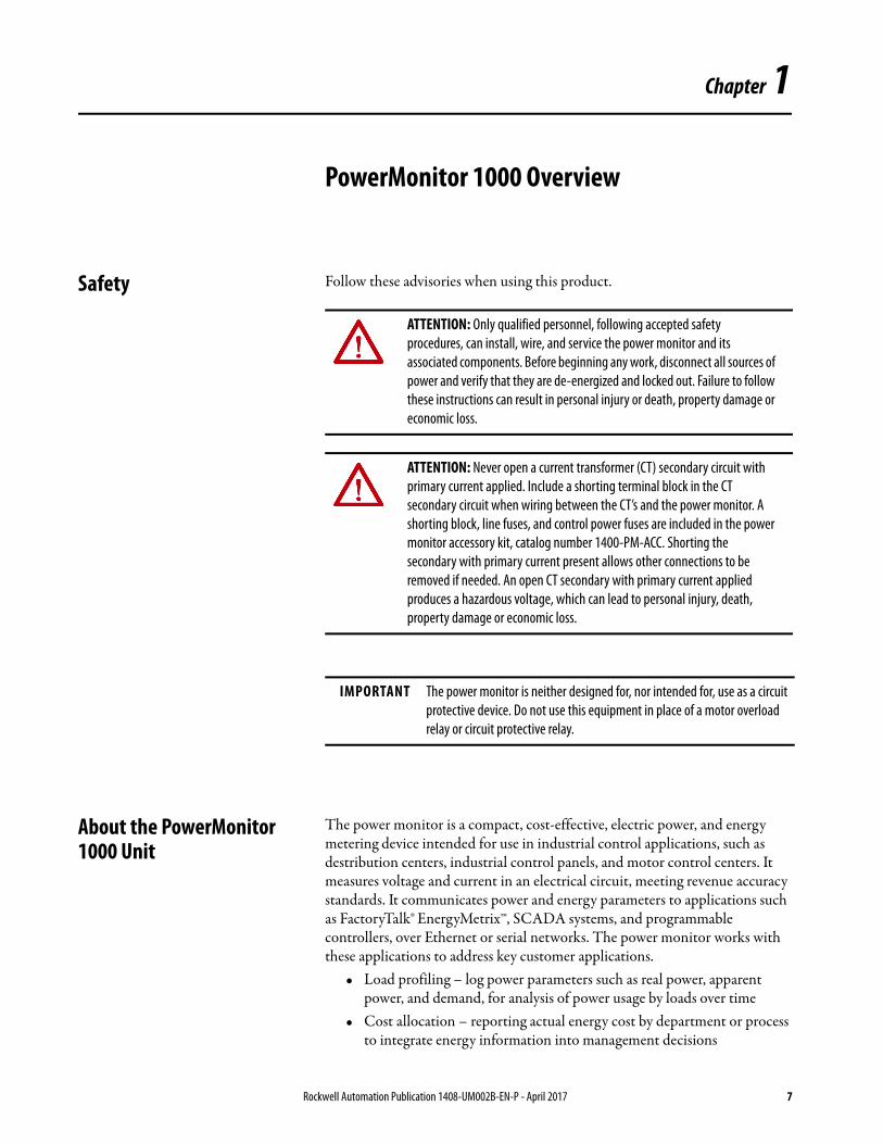
ATTENTION: Only qualified personnel, following accepted safety procedures, can install, wire, and service the power monitor and its associated components. Before beginning any work, disconnect all sources of power and verify that they are de-energized and locked out. Failure to follow these instructions can result in personal injury or death, property damage or economic loss.
ATTENTION: Never open a current transformer (CT) secondary circuit with primary current applied. Include a shorting terminal block in the CT secondary circuit when wiring between the CT’s and the power monitor. A shorting block, line fuses, and control power fuses are included in the power monitor accessory kit, catalog number 1400-PM-ACC. Shorting the secondary with primary current present allows other connections to be removed if needed. An open CT secondary with primary current applied produces a hazardous voltage, which can lead to personal injury, death, property damage or economic loss.
IMPORTANT The power monitor is neither designed for, nor intended for, use as a circuit protective device. Do not use this equipment in place of a motor overload relay or circuit protective relay.
Rockwell Automation Publication 1408-UM002B-EN-P - April 2017 7
Chapter 1 PowerMonitor 1000 Overview
• Billing and sub-billing – charging users of energy the actual usage cost rather than allocating by square footage or other arbitrary methods
• Power system monitoring and control – display and control power flow and energy utilization
• Capacitor bank control - provides real and reactive power values for use in a PLC-based control system
PowerMonitor 1000 Unit Features and Functions
The power monitor connects to the user’s three-phase or split-phase AC power system directly or through instrument transformers (PTs and CTs). The power monitor converts instantaneous voltage and current values to digital values, and uses the resulting digital values in calculations of voltage, current, power, and energy.
The power monitor family includes three models:• BC3 - Basic consumption meter• TS3 - Basic consumption and troubleshooting meter• EM3 – Energy, demand, and power monitor
PowerMonitor 1000 unit models TR1, TR2, EM1, and EM2 have been discontinued.
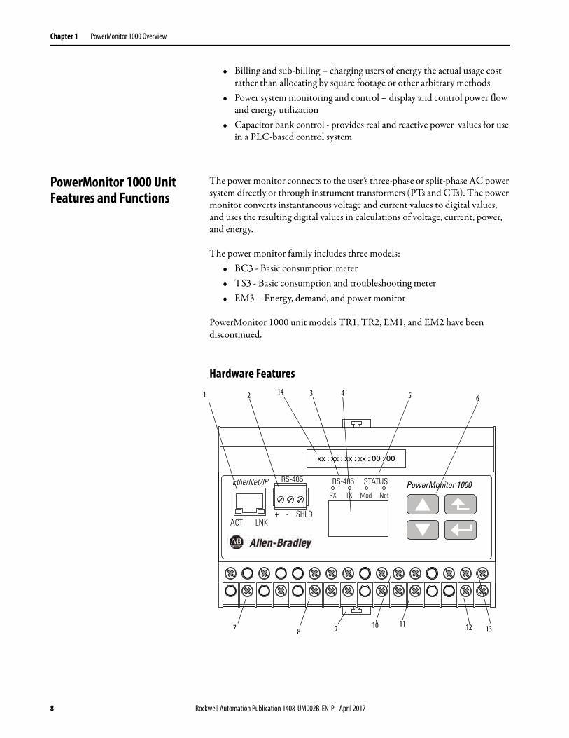
Hardware Features
PowerMonitor 1000EtherNet/IP
ACT LNK
STATUSRS-485RS-485
+ - SHLD
RX TX Mod Net
xx : xx : xx : xx : 00 : 00
1 2 3 4 5 6
7 810 11 12 139
14
8 Rockwell Automation Publication 1408-UM002B-EN-P - April 2017

PowerMonitor 1000 Overview Chapter 1
Table 1 - Hardware Features
Feature Description BC3 TS3 EM3
1. Ethernet network port - standard RJ-45 jack with status indicators
Ethernet network port hardware is included on all models. The port functions only on units ordered with or upgraded to the Ethernet network. The following protocols and functions are supported.• EtherNet/IP• Modbus TCP• HTML Web page for configuration and data accessLNK indicator
– Solid GREEN: IP link established– Off: no link established
ACT indicator– Flashing YELLOW: data present on Ethernet port– Off: no data activity present
X X X
2. Serial port - three-pin RS-485 connector All models include RS-485 serial communication that support the following protocols and functions.• DF1 half-duplex slave• DF1 full-duplex• Modbus RTU slave• Configuration by using terminal emulation software• DH-485
X X X
3. Serial port status indicators • TX indicator flashes YELLOW when data is being transmitted• RX indicator flashes YELLOW when data is being received
X X X
4. LCD • Unit configuration• Data display
– Not present on BC3 model
X X
5. Module and network status indicators • Module indicator– GREEN: Normal operation– Alternating RED/GREEN: Performing self-test– RED (solid or blinking): Initial power-up or failed self-test
• Network indicator– GREEN: Ethernet connection established– Blinking GREEN: Ethernet port looking for a connection– RED: Duplicate IP address detected
X X X
6. LCD interface buttons • Unit configuration• Data display navigation
– Not present on BC3 model
X X
7. Voltage-sensing wiring terminals
• Direct connect up to 600V AC three-phase line-to-line• Maximum nominal line-to-ground voltage 347V• Use potential transformers (PTs) for higher voltages
X X X
8. Current-sensing wiring terminals
• Nominal input current 5 A• Use current transformers (CTs) to connect to power system
X X X
9. DIN-rail clips • Top and bottom clips for mounting unit on DIN rail X X X
10. Status-input wiring terminalsRestore factory defaults wiring terminals (BC3)
• Two internally-powered inputs (TS3, EM3)• S2 can be used for demand period synchronization (TS3, EM3)• FD1 and FD2 can be used to restore factory default configuration (BC3).
X X X
11. Configuration-lock wiring terminals
• Wire together to prevent configuration changes X X X
12. KYZ-output wiring terminals • DPDT solid-state relay for signaling use – Not present on BC3 model
X X
13. Control power and ground wiring terminals
• 120…240V AC, 50…60 Hz X X X
14. MAC ID label • aa:bb:cc:dd:ee:ff, used when assigning an IP address using DHCP; X; X; X X X X
Rockwell Automation Publication 1408-UM002B-EN-P - April 2017 9
Chapter 1 PowerMonitor 1000 Overview
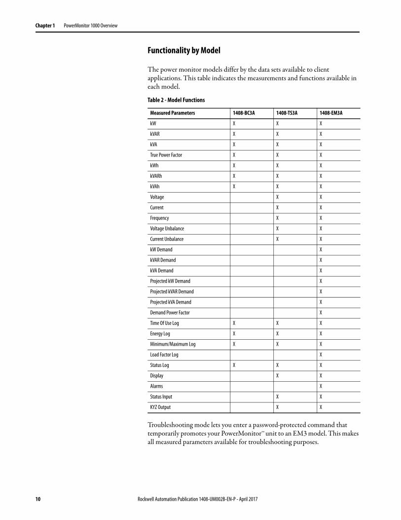
Functionality by Model
The power monitor models differ by the data sets available to client applications. This table indicates the measurements and functions available in each model.
Troubleshooting mode lets you enter a password-protected command that temporarily promotes your PowerMonitor™ unit to an EM3 model. This makes all measured parameters available for troubleshooting purposes.
Table 2 - Model Functions
Measured Parameters 1408-BC3A 1408-TS3A 1408-EM3A
kW X X X
kVAR X X X
kVA X X X
True Power Factor X X X
kWh X X X
kVARh X X X
kVAh X X X
Voltage X X
Current X X
Frequency X X
Voltage Unbalance X X
Current Unbalance X X
kW Demand X
kVAR Demand X
kVA Demand X
Projected kW Demand X
Projected kVAR Demand X
Projected kVA Demand X
Demand Power Factor X
Time Of Use Log X X X
Energy Log X X X
Minimum/Maximum Log X X X
Load Factor Log X
Status Log X X X
Display X X
Alarms X
Status Input X X
KYZ Output X X
10 Rockwell Automation Publication 1408-UM002B-EN-P - April 2017

PowerMonitor 1000 Overview Chapter 1
Communication Overview All PowerMonitor 1000 units come standard with an RS-485 serial communication port. Models with catalog numbers ending in -ENT are equipped with an Ethernet 10BaseT communication port. This section covers serial and Ethernet communication, the available protocols, and what protocols to use for your application.
What Can I Do Using Communication Networks?
When you use communication networks with the power monitor you can do the following things.
• Configure analog input parameters such as PT/CT ratios• Configure communication parameters such as IP address• Read real-time power and energy data• Read energy logs
Serial Communication
The RS-485 serial communication port allows serial communication to your power monitor. This port can be configured to communicate using the protocols listed the this table.
DH485 Protocol
DH485 is a token-passing protocol that allows messaging by up to 32 nodes on a serial network. The master is the node that owns the token; only the master can transmit messages. When a node has completed transmitting messages, it passes the token to the next node.
Table 3 - Serial Communication Protocols
Protocol Applications
DF1 Half-duplex Slave The DF1 Half-duplex Slave protocol can be used for point-to-point or multi-drop communication when using a DF1 Polling Master driver in RSLinx® Classic software, or using explicit messages from Rockwell Automation controllers communicating via DF1 Half-duplex Master.
DF1 Full-duplex The DF1 Full-duplex protocol can be used only for point-to-point communication using a RS-232 DF1 driver for RSLinx software, or when using explicit messages from Rockwell Automation controllers communicating via DF1 Full-duplex.
Modbus RTU Slave The Modbus RTU Slave protocol can be used for point-to-point or multi-drop communication with a client using the Modbus RTU Master protocol for PLC controller communication.
Auto-sense With auto-sense selected, the RS-485 port switches among the available serial protocols based on the format of the packets the port receives.
DH485 The DH485 protocol can be used for point-to-point or multi-drop communication using a 1747-PIC/AIC+ driver for RSLinx software, or when using explicit messages from Allen-Bradley controllers or HMI (PanelView™) terminals communicating via DH485.
ASCII The ASCII protocol is used with terminal emulation software to configure and read data using point-to-point communication.
TIP All devices communicating on a serial network must be configured with the same data rate and data format.
Rockwell Automation Publication 1408-UM002B-EN-P - April 2017 11

Chapter 1 PowerMonitor 1000 Overview
The power monitor does not initiate DH485 data messages. When requested, it transmits reply messages to the initiator when it gets the token, and then passes the token to its successor.
The DH485 protocol uses the same data table addressing as DF1 protocols. Please refer to the CSP file number column of PowerMonitor 1000 data tables.
The following configuration factors have a significant effect on network performance and must be considered when you plan a DH485 network.
• Number of Nodes - unnecessary nodes slows the data transfer rate. The maximum number of nodes on the network is 32. Fewer nodes are better.
• Node Addresses - best to start node addresses at 0 and assign in sequential order. Controllers cannot be node 0. Assigned the lowest numbered addresses to initiators such as personal computers.
• Communication Rate - higher is better. All devices must be at the same communication rate.
• Maximum Node Address - set as low as possible to reduce the time it takes to initialize the network.
Ethernet Network Communication
The Ethernet network communication port allows communication with your power monitor using a local-area-network (LAN). The Ethernet port can also be used to view the internal webpage of the power monitor. This Ethernet port uses a static IP address by default (DHCP address assignment optional), and can simultaneously communicate by using the protocols listed below. The Ethernet communication port supports 10 Mbps data rate, half-duplex.
EtherNet/IP Protocol
The power monitor supports the EtherNet/IP protocol for communicating via Ethernet or EtherNet/IP drivers in RSLinx Classic software, or when using explicit messages from Rockwell Automation controllers communicating via Ethernet or EtherNet/IP network.
Modbus TCP Protocol
Modbus TCP protocol is also supported for communicating via Modbus TCP for communication.
TIP PowerMonitor 1000 units only support DH485 Local Link messages and do not support Send and Receive Data (SRD) messages for DH485 non-token passing slave devices.
TIP When configuring Ethernet communication, verify that IP addresses do not conflict with the existing infrastructure, and that subnet masks and gateways are properly set.
12 Rockwell Automation Publication 1408-UM002B-EN-P - April 2017

Chapter 2
Installation and Setup
Pre-installation Setup We recommend that you perform at least a minimal setup of the Ethernet PowerMonitor™ 1000 unit prior to installation. This setup establishes a security policy holder and sets up the network port addressing so that the unit setup can be completed over the Ethernet network after the unit is installed, wired, and power is applied.
This section describes the equipment and steps needed to perform pre-installation setup.
Equipment Required
The following equipment is needed for initial setup of the unit:• A personal computer that can run Internet Explorer web browser• A standard or cross-over patch Ethernet communication cable• A power cord
Set up your computer LAN port with a fixed address. These are the recommended settings:
• IP address: 192.168.254.250• Subnet mask: 255.255.0.0• Gateway: none required
IMPORTANT Pre-installation setup of the BC3 model is especially important since the BC3 model has no display or keypad, and therefore all configuration must be done by using communication.
IMPORTANT If the catalog number of your power monitor ends in -485, refer to the Use Terminal Emulation Software for Setup section.
Rockwell Automation Publication 1408-UM002B-EN-P - April 2017 13

Chapter 2 Installation and Setup
Temporarily Connect Power
Connect an un-plugged power cord to the PowerMonitor 1000 unit as shown in Figure 1. L1 to L2 voltage must be 120…240V AC, 50…60 Hz. The ground terminal must be connected to earth ground. After the power cord is connected, plug it in to a suitable electrical outlet. After the power-on self-test (POST) is complete, the left status indicator remains lit.
Figure 1 - Temporary Power Connection
Connect the Ethernet Network
Connect the unit Ethernet port to your computer LAN port. The following methods can be used:
• Connect by using a cross-over UTP patch cable• Connect by using two straight through UTP patch cables and a hub or
switch• Connect by using a straight through UTP patch cable, if your computer
NIC supports Auto MDI-X
14 Rockwell Automation Publication 1408-UM002B-EN-P - April 2017
Installation and Setup Chapter 2
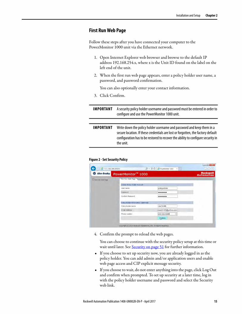
First Run Web Page
Follow these steps after you have connected your computer to the PowerMonitor 1000 unit via the Ethernet network.
1. Open Internet Explorer web browser and browse to the default IP address 192.168.254.x, where x is the Unit ID found on the label on the left end of the unit.
2. When the first run web page appears, enter a policy holder user name, a password, and password confirmation.
You can also optionally enter your contact information.
3. Click Confirm.
Figure 2 - Set Security Policy
4. Confirm the prompt to reload the web pages.
You can choose to continue with the security policy setup at this time or wait until later. See Security on page 51 for further information.
• If you choose to set up security now, you are already logged in as the policy holder. You can add admin and/or application users and enable web page access and CIP explicit message security.
• If you choose to wait, do not enter anything into the page, click Log Out and confirm when prompted. To set up security at a later time, log in with the policy holder username and password and select the Security web link.
IMPORTANT A security policy holder username and password must be entered in order to configure and use the PowerMonitor 1000 unit.
IMPORTANT Write down the policy holder username and password and keep them in a secure location. If these credentials are lost or forgotten, the factory default configuration has to be restored to recover the ability to configure security in the unit.
Rockwell Automation Publication 1408-UM002B-EN-P - April 2017 15

Chapter 2 Installation and Setup
With security disabled, the unit configuration is protected from inadvertent or unauthorized changes by a Table Password, with a default value of 0. You can assign a different table password by using the Advanced Configuration web link.
With security enabled, an admin user must be logged in to the web page to modify the unit configuration. The table password fields are disabled and are ignored by the unit.
Figure 3 - Security Enabled
TIP If you have updated firmware in a Series A PowerMonitor 1000 unit, the table password remains the same as it had been prior to the update.
16 Rockwell Automation Publication 1408-UM002B-EN-P - April 2017

Installation and Setup Chapter 2
Initial Network Configuration
The next step is to assign the Ethernet network address. Follow these steps to assign a fixed address.
1. Expand the Configuration Options folder and select Ethernet Configuration.
2. Enter the table password, the four bytes of the IP address, subnet mask, and gateway address.
3. When the values are entered, click Apply to store and apply the new network address.
Your power monitor unit is now ready to be installed. The unit is capable of communicating on the Ethernet network and ready to accept your final configuration.
Mount the PowerMonitor 1000 Unit
Mount the PowerMonitor 1000 unit in a suitable protective enclosure. Select an enclosure that protects the unit from atmospheric contaminants, such as oil, water, moisture, dust, corrosive vapors, and other harmful airborne substances.
The enclosure must protect against personal contact with energized circuits. The ambient temperature within the enclosure must remain within the limits listed in Appendix B, Specifications. Select an enclosure that provides adequate clearance for ventilation and wiring for the power monitor and other equipment to be installed within the enclosure.
See PowerMonitor 1000 Unit Dimensions on page 19 for dimensions and spacing guidelines for the power monitor.
When installed within a substation or switchgear lineup, we recommend that the power monitor be mounted within a low-voltage cubicle, isolated from medium and high-voltage circuits. Be sure that the mounting panel is properly connected to a low-impedance earth ground.
Mount the enclosure in a position that allows full access to the unit. The power monitor can be mounted on a panel or a DIN rail.
Rockwell Automation Publication 1408-UM002B-EN-P - April 2017 17
Chapter 2 Installation and Setup
Panel Mount
Follow these steps to mount the unit on a panel or any flat surface.
1. Extend the top and bottom DIN rail clips to the panel mount position.
2. Insert a small screwdriver under the spring pin to move the clip, lift it, and pull the clip forward until it extends approximately 6 mm (0.25 in.) from the enclosure.
3. Release the pin and lock the clip in the panel mount position.
4. Mount the unit by using three M4 or #8 machine screws.
DIN Rail Mount
You can mount the unit on standard 35 x 7.5 mm (EN 50 022 – 35 x 7.7) DIN rail. To mount on a DIN rail, leave the mounting clips retracted so the mounting holes are hidden behind the unit.
Install
Follow these steps to mount the unit on a DIN rail.
1. Tilt the bottom of the unit slightly away from the rail until the notches grab onto the top flange of the DIN rail.
2. Push the bottom of the enclosure forward towards the DIN rail.
The spring-loaded clip snaps onto the bottom of the rail and holds the unit firmly in place.
Remove
Follow these steps to remove the unit from a DIN rail.
1. Insert a small screwdriver into the exposed slot in the tab to remove the unit from the DIN rail.
2. Pull enclosure forward and remove from the rail.
18 Rockwell Automation Publication 1408-UM002B-EN-P - April 2017
Installation and Setup Chapter 2
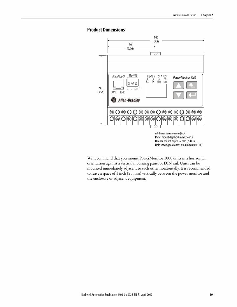
Product Dimensions
We recommend that you mount PowerMonitor 1000 units in a horizontal orientation against a vertical mounting panel or DIN rail. Units can be mounted immediately adjacent to each other horizontally. It is recommended to leave a space of 1 inch (25 mm) vertically between the power monitor and the enclosure or adjacent equipment.
PowerMonitor 1000EtherNet/IP
ACT LNK
STATUSRS-485RS-485
+ - SHLD
RX TX Mod Net
70(2.76)
140(5.5)
90(3.54)
All dimensions are mm (in.).Panel mount depth 59 mm (2.4 in.).DIN-rail mount depth 62 mm (2.44 in.).Hole spacing tolerance: ±0.4 mm (0.016 in.).
Rockwell Automation Publication 1408-UM002B-EN-P - April 2017 19

Chapter 2 Installation and Setup
Wire the PowerMonitor 1000 Unit
The power monitor has finger-safe screw terminals with pressure plates for all wiring connections.
Figure 4 - Terminal Block Layout (BC3 model)
Figure 5 - Terminal Block Layout (TS3, EM3 models)
Voltage Sensing
The PowerMonitor 1000 unit monitors a variety of three-phase and single-phase circuits. Voltages of up to 600V AC line-to-line (347V AC line-to-ground) can be connected directly. Higher voltages require potential transformers (PTs), also known as voltage transformers (VTs).
Wiring must conform to all applicable codes and standards. In particular, you must provide suitable overcurrent protection with current and interrupting ratings that are selected to help protect the wiring. The following items are included in the power monitor accessory kit, catalog number 1400-PM-ACC:
• Three 10 A fuses and blocks to hep protect voltage sensing wiring• A 1 A fuse and block to help protect control power wiring• An 8-pole shorting terminal block for CT wiring
The accessory kit is available from your local Allen-Bradley distributor or Rockwell Automation sales representative.
Pay particular attention to correct phasing and polarity of voltage connections. The diagrams use the dot convention to indicate transformer polarity. The dot indicates the H1 and X1 terminals on the high side and low side of the transformer respectively.
Wire Type Wire Size Range Wires per Terminal Recommended Torque
Cu - 75 °C (167 °F) 0.33…0.21 mm2
(22 … 14 AWG)2 max per terminal, sol-sol or str-str only (no mixed pairs)
0.8 N•m (7 lb•in)
V1
V2
V3
VN
I1+
I1-
I2+
I2-
I3+
I3-
NC
NC
FD1
CF1
FD2
CF2
L2L1
NC NC NC
V1
V2
V3
VN
I1+
I1-
I2+
I2-
I3+
I3-
S1
NC
S2
CF
SCOM
CF1
L2L1
Y K Z
20 Rockwell Automation Publication 1408-UM002B-EN-P - April 2017
Installation and Setup Chapter 2
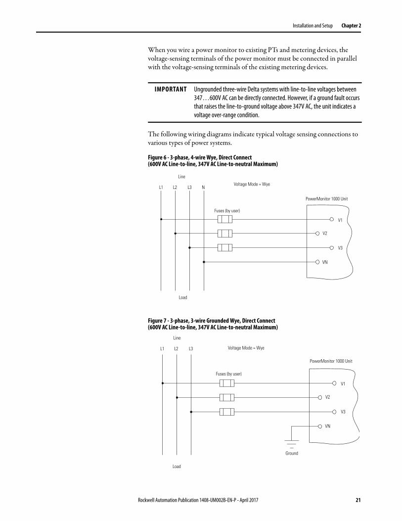
When you wire a power monitor to existing PTs and metering devices, the voltage-sensing terminals of the power monitor must be connected in parallel with the voltage-sensing terminals of the existing metering devices.
The following wiring diagrams indicate typical voltage sensing connections to various types of power systems.
Figure 6 - 3-phase, 4-wire Wye, Direct Connect (600V AC Line-to-line, 347V AC Line-to-neutral Maximum)
Figure 7 - 3-phase, 3-wire Grounded Wye, Direct Connect (600V AC Line-to-line, 347V AC Line-to-neutral Maximum)
IMPORTANT Ungrounded three-wire Delta systems with line-to-line voltages between 347…600V AC can be directly connected. However, if a ground fault occurs that raises the line-to-ground voltage above 347V AC, the unit indicates a voltage over-range condition.
Line
Load
L1 L2 L3 NVoltage Mode = Wye
Fuses (by user)
PowerMonitor 1000 Unit
V1
V2
V3
VN
Line
Load
Ground
L1 L2 L3 Voltage Mode = Wye
Fuses (by user)
PowerMonitor 1000 Unit
V1
V2
V3
VN
Rockwell Automation Publication 1408-UM002B-EN-P - April 2017 21

Chapter 2 Installation and Setup
Figure 8 - 3-phase, 4-wire Wye with Potential Transformers
Figure 9 - 3-phase, 3-wire Grounded Wye with Potential Transformers
Line
LoadGround
Ground
L1 L2 L3 N Voltage Mode = Wye
Fuses (by user)PTs
(by user)
PowerMonitor 1000 Unit
V1
V2
V3
VN
Line
Load GroundGround
Ground
L1 L2 L3Voltage Mode = Wye
Fuses (by user)PTs
(by user)
PowerMonitor 1000 Unit
V1
V2
V3
VN
22 Rockwell Automation Publication 1408-UM002B-EN-P - April 2017

Installation and Setup Chapter 2
Figure 10 - 3-phase, 3-wire Open Delta with Two Potential Transformers
Figure 11 - Split-phase, Direct Connect (600V AC Line-to-line, 347V AC Line-to-neutral Maximum)
IMPORTANT Open delta voltage mode cannot be used in a system with 132 (ACB) phase rotation.
Line
Load
Ground Ground
L1 L2 L3 Voltage Mode = Open Delta
Fuses (by user)PTs
(by user)
PowerMonitor 1000 Unit
V1
V2
V3
VN
Line
Load
L1 L2 N Voltage Mode = Split-phase
Fuses (by user)
PowerMonitor 1000 Unit
V1
V2
V3
VN
Rockwell Automation Publication 1408-UM002B-EN-P - April 2017 23
Chapter 2 Installation and Setup
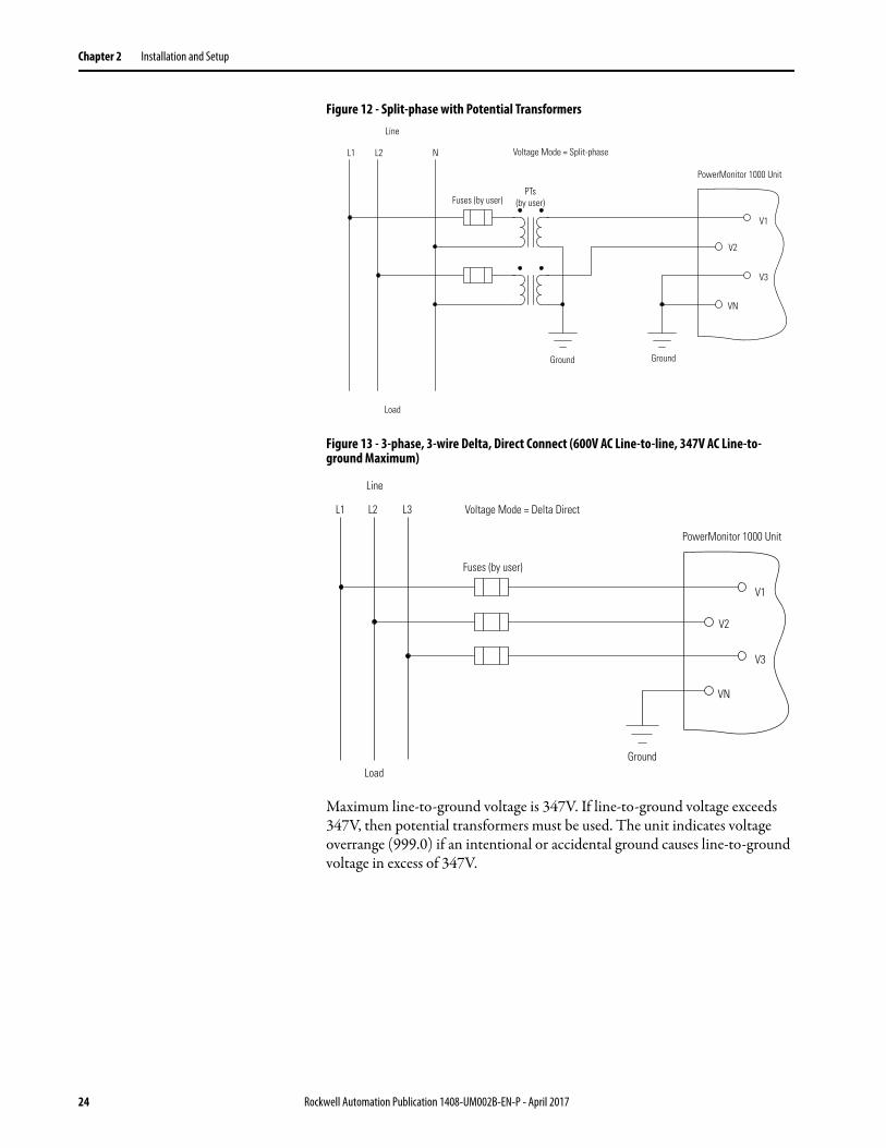
Figure 12 - Split-phase with Potential Transformers
Figure 13 - 3-phase, 3-wire Delta, Direct Connect (600V AC Line-to-line, 347V AC Line-to-ground Maximum)
Maximum line-to-ground voltage is 347V. If line-to-ground voltage exceeds 347V, then potential transformers must be used. The unit indicates voltage overrange (999.0) if an intentional or accidental ground causes line-to-ground voltage in excess of 347V.
Line
Load
Ground Ground
L1 L2 N Voltage Mode = Split-phase
Fuses (by user)PTs
(by user)
PowerMonitor 1000 Unit
V1
V2
V3
VN
Line
LoadGround
L1 L2 L3 Voltage Mode = Delta Direct
Fuses (by user)
PowerMonitor 1000 Unit
V1
V2
V3
VN
24 Rockwell Automation Publication 1408-UM002B-EN-P - April 2017
Installation and Setup Chapter 2
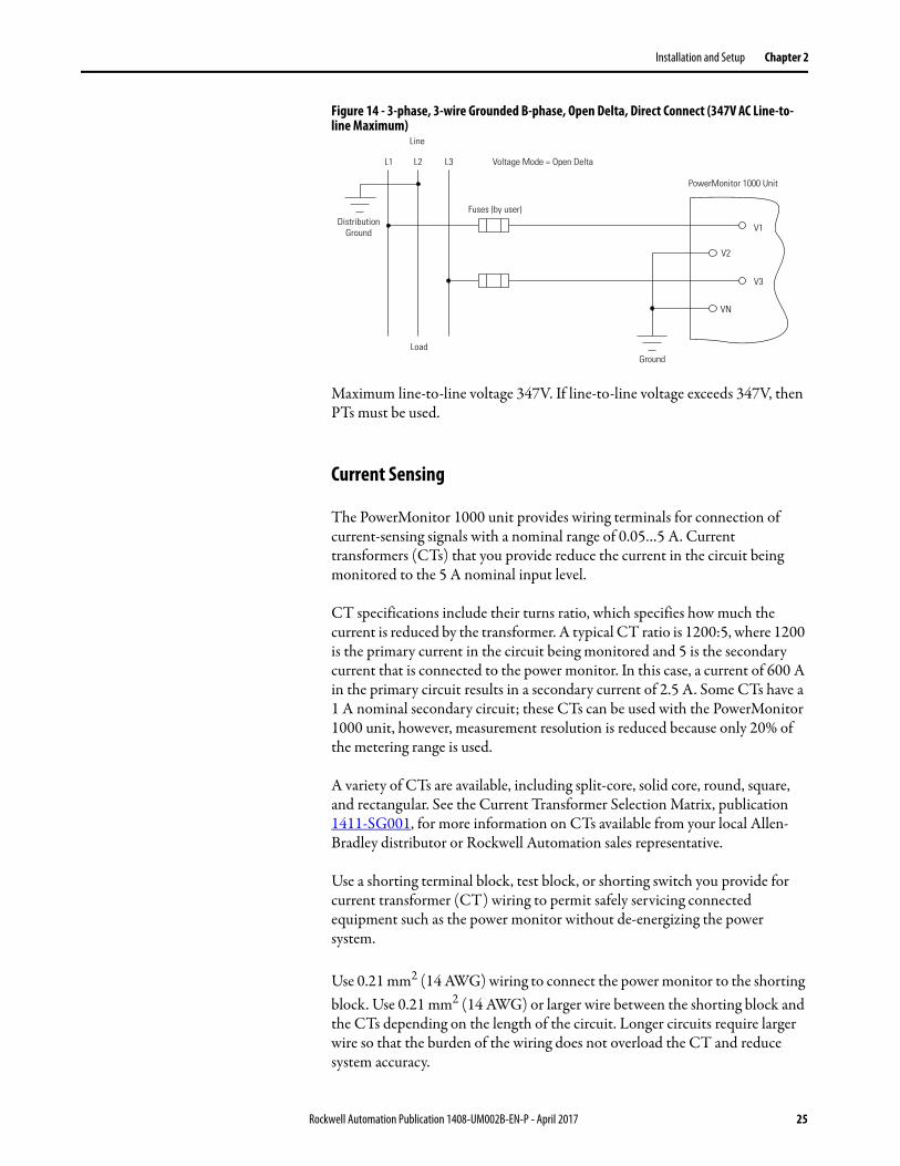
Figure 14 - 3-phase, 3-wire Grounded B-phase, Open Delta, Direct Connect (347V AC Line-to-line Maximum)
Maximum line-to-line voltage 347V. If line-to-line voltage exceeds 347V, then PTs must be used.
Current Sensing
The PowerMonitor 1000 unit provides wiring terminals for connection of current-sensing signals with a nominal range of 0.05…5 A. Current transformers (CTs) that you provide reduce the current in the circuit being monitored to the 5 A nominal input level.
CT specifications include their turns ratio, which specifies how much the current is reduced by the transformer. A typical CT ratio is 1200:5, where 1200 is the primary current in the circuit being monitored and 5 is the secondary current that is connected to the power monitor. In this case, a current of 600 A in the primary circuit results in a secondary current of 2.5 A. Some CTs have a 1 A nominal secondary circuit; these CTs can be used with the PowerMonitor 1000 unit, however, measurement resolution is reduced because only 20% of the metering range is used.
A variety of CTs are available, including split-core, solid core, round, square, and rectangular. See the Current Transformer Selection Matrix, publication 1411-SG001, for more information on CTs available from your local Allen-Bradley distributor or Rockwell Automation sales representative.
Use a shorting terminal block, test block, or shorting switch you provide for current transformer (CT) wiring to permit safely servicing connected equipment such as the power monitor without de-energizing the power system.
Use 0.21 mm2 (14 AWG) wiring to connect the power monitor to the shorting block. Use 0.21 mm2 (14 AWG) or larger wire between the shorting block and the CTs depending on the length of the circuit. Longer circuits require larger wire so that the burden of the wiring does not overload the CT and reduce system accuracy.
Line
LoadGround
L1 L2 L3 Voltage Mode = Open Delta
Fuses (by user)
PowerMonitor 1000 Unit
DistributionGround V1
V2
V3
VN
Rockwell Automation Publication 1408-UM002B-EN-P - April 2017 25

Chapter 2 Installation and Setup
When you wire a power monitor to existing CTs and metering devices, the current-sensing terminals of the power monitor must be connected in series with the CT secondary and current-sensing terminals of the existing metering devices.
Do not install overcurrent protection or non-shorting disconnecting means in CT secondary wiring. Connect the current-sensing circuit to a low-impedance earth ground at only one point.
Pay particular attention to the correct phasing and polarity of current-sensing connections. The diagrams use the dot convention to indicate transformer polarity. The dot indicates the H1 and X1 terminals on the primary and secondary of the CT respectively. CTs with pigtail leads typically indicate the X1 (dotted) terminal with white wire and X2 with black wire. This convention runs counter to common wiring practicess in industrial settings, and can result in incorrect polarity of CT wiring. Phasing of the CTs must correspond to the phasing of the voltage-sensing connections.
The following wiring diagrams indicate typical current sensing connections to various types of power systems.
Figure 15 - 3-phase, 3- or 4-wire, 3-current Transformers
Line
Load Ground
L1 L2 L3N
(if used) Voltage Mode = Wye, Direct Delta, or Open Delta
CTs (by user)
Shorting TerminalBlock (by user)
PowerMonitor 1000 Unit
I1+
I1-
I2+
I3+
I2-
I3-
26 Rockwell Automation Publication 1408-UM002B-EN-P - April 2017

Installation and Setup Chapter 2
Figure 16 - 3-phase, 3-wire, 2-current Transformers
You can use two CTs only on three-wire systems.
Figure 17 - Split-phase, 2-current Transformers
Line
Load
Ground
L1 L2 L3 Voltage Mode = Direct Delta or Open Delta
CTs (by user)
Shorting TerminalBlock (by user)
PowerMonitor 1000 Unit
I1+
I1-
I2+
I3+
I2-
I3-
Line
Load Ground
L1 L2 N Voltage Mode = Split Phase
CTs (by user)
Shorting TerminalBlock (by user)
PowerMonitor 1000 Unit
I1+
I1-
I2+
I3+
I2-
I3-
Rockwell Automation Publication 1408-UM002B-EN-P - April 2017 27

Chapter 2 Installation and Setup
Special Wiring Modes
There are two special wiring modes for the power monitor.
1PT 1CT Line-to-line
This special wiring mode is designed for use in capacitor bank controllers. Traditional capacitor bank control measures Vbc and Ia to calculate reactive power and power factor. In this mode, the power monitor returns values as if it were configured in Delta mode. Three-phase values are estimated assuming a balanced load.
The following wiring diagram indicates the connections for the 1PT 1CT Line-to-line mode. A PT must be used. Wiring diagnostics are disabled in this mode.
Figure 18 - 1PT 1CT Line-to-line
V1
L1 L2 L3
V2
VN
V3
Load
Line
Ground
Voltage Mode = 1PT1CT Line-to-line
PowerMonitor 1000
Fuses(by user)
PT(by user)
CT(by user)
Shorting terminalblock (by user)
I1+
I2+
I1-
I2-Ground
28 Rockwell Automation Publication 1408-UM002B-EN-P - April 2017

Installation and Setup Chapter 2
1PT 1CT Line-to-neutral
This special wiring mode is designed for use in new capacitor bank controller installations where the legacy metering connections described in the preceding section do not apply. In this mode, the power monitor returns values as if it were configured in Wye mode. Three-phase values are estimated assuming a balanced load.
The following wiring diagram indicates the connections for the 1PT 1CT Line-to-neutral mode. A PT is optional. Wiring diagnostics are disabled in this mode.
Figure 19 - 1PT and 1CT Line-to-Neutral
Status Inputs (except BC3 model)
One or two dry (non-powered) contacts can be connected to the power monitor status inputs. The power monitor 24V DC status input derives power from its internal power supply.
Connect status inputs by using shielded, twisted-pair cable with the shield connected to the ground bus or other low-impedance earth ground at one end only. The diagram indicates typical status input wiring.
Figure 20 - Status Inputs (S1, S2)
V1
L1 L2 L3 N
V2
VN
V3
Load
Line
Connect to groundONLY if PT is used
Voltage Mode = 1PT1CT Line-to-neutral
PowerMonitor 1000
Fuses(by user)
PT(by user,if used)
CT(by user)
Shorting terminalblock (by user)
I1+
I2+
I1-
I2-Ground
Contact 1
Contact 2
Ground
SCOM
S2
S1
Rockwell Automation Publication 1408-UM002B-EN-P - April 2017 29
Chapter 2 Installation and Setup
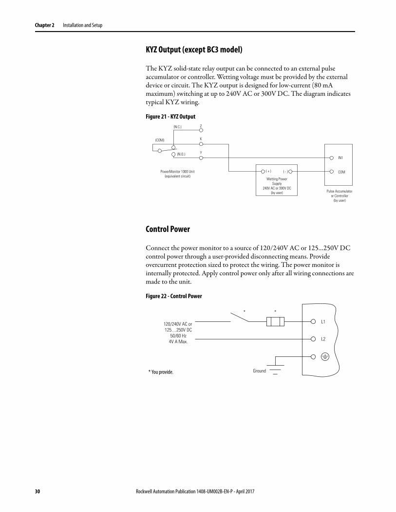
KYZ Output (except BC3 model)
The KYZ solid-state relay output can be connected to an external pulse accumulator or controller. Wetting voltage must be provided by the external device or circuit. The KYZ output is designed for low-current (80 mA maximum) switching at up to 240V AC or 300V DC. The diagram indicates typical KYZ wiring.
Figure 21 - KYZ Output
Control Power
Connect the power monitor to a source of 120/240V AC or 125…250V DC control power through a user-provided disconnecting means. Provide overcurrent protection sized to protect the wiring. The power monitor is internally protected. Apply control power only after all wiring connections are made to the unit.
Figure 22 - Control Power
PowerMonitor 1000 Unit(equivalent circuit)
Wetting PowerSupply
240V AC or 300V DC(by user) Pulse Accumulator
or Controller(by user)
( + ) ( - )
IN1
COM
(N.C.) Z
(COM)
(N.O.)
K
Y
120/240V AC or 125…250V DC
50/60 Hz4V A Max.
Ground
L1
L2
* *
* You provide.
30 Rockwell Automation Publication 1408-UM002B-EN-P - April 2017
Installation and Setup Chapter 2
Connect Communication
The following sections provide information on connecting Serial Communication and Ethernet Communication to the power monitor.
Serial Communication
Use point-to-point wiring between one power monitor and a computer or other data terminal for HyperTerminal communication and DF1 full-duplex communication. DF1 half-duplex, Modbus RTU, and DH-485 protocols permit a point-to-point or multi-drop network configuration.
Install multi-drop RS-485 communication wiring in a daisy-chain configuration. Up to 32 nodes can be connected together in a network. We recommend the use of Belden 9841 two-conductor shielded cable or equivalent. The maximum cable length is 1219 m (4000 ft). Use of a star or bridging topology is not recommended and can result in signal distortion unless impedance is matched for each spur (star topology) or network (bridge topology).
You must provide an RS-232 to RS-485 converter for communication between the power monitor serial port and an RS-232 port in an external device such as a computer or programmable controller. Examples of converters include the following:
• Allen-Bradley® catalog number 1761-NET-AIC • B&B Electronics, Inc. part number 485SD9TB (DB-9 connection)• B&B Electronics, Inc. part number USOPTL4 (USB connection)
At one end of each cable segment, connect the cable shields to the SHLD terminal of the power monitor serial port or converter. The SHLD connection provides a low-impedance ground for high-frequency noise while attenuating DC or line-frequency signals.
If needed, install 150 Ω, ¼ W terminating resistors at the ends of the daisy-chain cable. Some RS-485 converters are equipped with internal terminating resistors. Contact the manufacturer of the converter for additional information.
TIP Wiring to the power monitor RS-485 port is the same as wiring to the PowerMonitor 3000 RS-485 port, but not the same as the PowerMonitor 500 RS-485 port.
Rockwell Automation Publication 1408-UM002B-EN-P - April 2017 31

Chapter 2 Installation and Setup
See Use Communication to Set Up on page 49 for information on configuring serial communication parameters such as data rate and node addresses.
Figure 23 - RS-485 Point-to-point Typical Wiring
Figure 24 - RS-485 Multi-drop Typical Wiring
Terminals Wire Range(1)
(1) 75 °C Cu wire only, 1 to 2 conductors per terminal (sol-sol or str-str).
Tightening Torque
V1, V2, V3, VN, I1+ I2+, I3+, I1-, I2-, I3-, S1, S2, SCOM, NC, CR, CF1, L1, L2, Y, K, Z
0.32…4 mm2 (22…14 AWG) 0.8 N•m (7 lb•in)
RS-485 Communication 0.32…4 mm2 (22…14 AWG) 0.56 N•m (5 lb•in)
24V DC (by user)
RS-485
+
-
SHLD
+
-
SHLD
+
-
SHLD
+
-
SHLD
*
*
PowerMonitor 1000
* 150 W Terminating Resistor (if used)
PowerMonitor 1000
PowerMonitor 1000PowerMonitor 1000
RS-485 RS-485
RS-485
Nine-pin Null Modem Cable(Female/Female)To Computer
2RS-485 Wiring:2/C Shielded Cable 0.32…4 mm (22…14 AWG)Connect A on converter to - on each PowerMonitor 1000.Connect B on converter to + on each PowerMonitor 1000.Connect shield at one end only of each link.Maximum cable length 1219 m (4000 ft.).
RS-485 to RS-232 Converter
Examples:Allen-Bradley 1761-NET-AIC (shown)B&B Electronics 485SD9TB or USOPTL4
TERM
A
B
COM
SHLD
CHS GND
CHS GND
RS-232
24V DC
DC NEUT
GRND
32 Rockwell Automation Publication 1408-UM002B-EN-P - April 2017

Installation and Setup Chapter 2
Ethernet Communication
The power monitor with optional Ethernet network communication connects easily to industry-standard Ethernet hubs and switches by using standard UTP (unshielded twisted-pair) cables with RJ-45 connectors.
Typical Ethernet connections are shown in this diagram.
Figure 25 - Ethernet Network Typical Connections
Ground the PowerMonitor 1000 Unit
In solid-state systems, grounding helps limit the effects of noise due to electromagnetic interference (EMI). Run the ground connection from the ground terminal of the power monitor to the ground bus or other low-impedance earth ground prior to connecting the control power or any other connections. Use 0.21 mm2 (14 AWG) wire.
Table 4 - Ethernet Communication Cable
Terminal Signal Function
1 TX+ Transmit + (TX+)
2 TX- Transmit - (TX-)
3 RX+ Receive + (RX+)
4
5
6 RX- Receive - (RX-)
7
8
PowerMonitor 1000EtherNet/IP
ACT LNK
STATUSRS-485RS-485
+ - SHLD
RX TX Mod Net
PowerMonitor 1000EtherNet/IP
ACT LNK
STATUSRS-485RS-485
+ - SHLD
RX TX Mod NetPowerMonitor 1000EtherNet/IP
ACT LNK
STATUSRS-485RS-485
+ - SHLD
RX TX Mod Net
Computer
LAN/WAN
Ethernet Switch
UTP Patch Cable (typical)
PowerMonitor 1000 Unit PowerMonitor 1000 Unit PowerMonitor 1000 Unit
Rockwell Automation Publication 1408-UM002B-EN-P - April 2017 33

Chapter 2 Installation and Setup
Grounding is also required in the voltage and current sensing circuits to limit the maximum voltage to ground for safety. Make all grounds to a common ground bus or terminal.
Set Up the PowerMonitor 1000 Unit
Although the power monitor ships from the factory with default settings, you need to configure it for your particular requirements. You can configure the power monitor by using the LCD interface (except for the BC3 model), a serial terminal emulation application, a Web interface, or other software. This section describes, in general, methods for setting up the power monitor.
Table 5 summarizes the setup options in the PowerMonitor 1000 unit.
Table 5 - Set Up Options
Category Configuration Item Classification BC3 TS3 EM3 For More Information
Analog Input Configuration Voltage Mode Required Analog Input Setup on page 56
PT Ratio
CT Ratio
System Power Factor Optional(1)
Date and Time Required(2) Date and Time Functions on page 67
Advanced Configuration New Table Password Optional Miscellaneous Functions on page 80
Metering Averaging Voltage, Current, and Frequency Metering on page 66
Log Status Inputs N/A Miscellaneous Functions on page 80
Daylight Saving Time Date and Time Functions on page 67
KYZ Output Setup N/A I/O Functions on page 75
Demand Setup N/A N/A Demand Metering on page 63
Action on Error Miscellaneous Functions on page 80
User Configurable Table Parameter selections for Assembly Instance 1
Optional N/A Implicit Messaging (Class 1 Connection) on page 107
Ethernet Configuration IP, Subnet Mask, Gateway Required(3) Optional EtherNet/IP on page 85
SNTP Optional Date and Time Functions on page 67
Demand Broadcast N/A N/A Demand Metering on page 63
RS-485 Configuration Protocol, Communication Rate, Delay, Data Format
Required(4) Use Terminal Emulation Software for Setup on page 44
(1) Can change for effective Wiring Diagnostics.
(2) Data logging uses Date and Time.
(3) Required for units with Ethernet.
(4) Required for units with only RS-485, optional on Ethernet units.
34 Rockwell Automation Publication 1408-UM002B-EN-P - April 2017

Installation and Setup Chapter 2
Use Optional Software
FactoryTalk EnergyMetrix software (with the RT option) provides configuration interfaces for the power monitor, including the ability to upload, edit, download, and back up the unit configuration on a server. Refer to the FactoryTalk EnergyMetrix Software user manual, publication FTEM-UM00 , or help files for information on configuring the power monitor using software.
Contact your local Allen-Bradley distributor, Rockwell Automation sales representative, or visit http://www.rockwellautomation.com/rockwellsoftware/ for more information on available software packages.
Use a Web Browser for Setup
You can use a web browser to view data and change configuration settings on your meter. Follow these steps to use the Web interface.
1. Use a computer that has network access to the power monitor, open your web browser, type the unit IP address in the address field, and press Enter.
The power monitor's home page displays in your browser.
The home page displays general information about the power monitor. The navigation menu is on the left.
2. In the left navigations pane, click Configuration Options to open the list of setup pages.
3. Click Analog Input Configuration to open the analog input setup page.
Rockwell Automation Publication 1408-UM002B-EN-P - April 2017 35

Chapter 2 Installation and Setup
• If security is disabled, the Table Password and all available parameters are active. Enter the correct Table Password in addition to the desired values of the setup parameters.
• If security is enabled, you must log in with an Administrator account before setting up the unit. Until you log in, all parameters in the setup pages are inactive (grayed out). After you have logged in, the Table Password is inactive, as are any setup parameters that do not apply to the model of your PowerMonitor 1000 unit.
4. Select the Voltage Mode from the list, and enter values for PT primary, PT secondary, and CT primary. a. If applicable, select a different System PF Setting. b. If security is disabled, enter the correct Table Password. c. Click Apply when done.
A message appears to indicate the status of the setup change. The happy path indication is:
IMPORTANT Setup pages operate differently depending on whether security is enabled or disabled.
TIP Refer to Analog Input Setup on page 56 for additional information on parameter values and other setup selections.
36 Rockwell Automation Publication 1408-UM002B-EN-P - April 2017

Installation and Setup Chapter 2
Other messages can appear, such as the following:• Password Rejected! - with security disabled, the Table Password
entered is incorrect• Configuration Item Out of Range! - indicating that a parameter value
exceeds its permitted range
5. Continue to set up the unit by selecting the remaining setup pages (for example, Date and Time and Advanced Configuration), entering setup parameters, and making selections from lists.
6. Click Apply to save your settings.
Use the LCD Screen (TS3 and EM3 models)
All models, except the BC3 model, include an onboard LCD for viewing and configuration. Buttons are provided to control the display. The display has three modes of operation:
• Display mode lets you select and view parameters including metering, event log, and self-test information.
• Program mode lets you change configuration parameters, with security against unauthorized configuration changes. Each power monitor is password protected.
• Edit mode lets you modify the selected parameters. In Edit mode, a highlight cursor appears under the value of the parameter being modified, starting at the right-hand (least significant) digit.
The diagram and table shows the LCD interface buttons and their functions.
Figure 26 - LCD Interface
PowerMonitor 1000RS-485 STATUS
RX TX Mod Net
Up Arrow Escape
EnterDown Arrow
Rockwell Automation Publication 1408-UM002B-EN-P - April 2017 37
Chapter 2 Installation and Setup
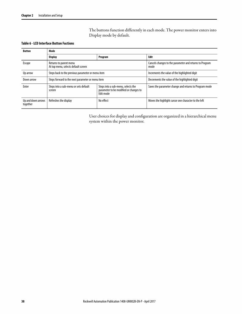
The buttons function differently in each mode. The power monitor enters into Display mode by default.
User choices for display and configuration are organized in a hierarchical menu system within the power monitor.
Table 6 - LCD Interface Button Fuctions
Button Mode
Display Program Edit
Escape Returns to parent menuAt top menu, selects default screen
Cancels changes to the parameter and returns to Program mode
Up arrow Steps back to the previous parameter or menu item Increments the value of the highlighted digit
Down arrow Steps forward to the next parameter or menu item Decrements the value of the highlighted digit
Enter Steps into a sub-menu or sets default screen
Steps into a sub-menu, selects the parameter to be modified or changes to Edit mode
Saves the parameter change and returns to Program mode
Up and down arrows together
Refreshes the display No effect Moves the highlight cursor one character to the left
38 Rockwell Automation Publication 1408-UM002B-EN-P - April 2017
Installation and Setup Chapter 2
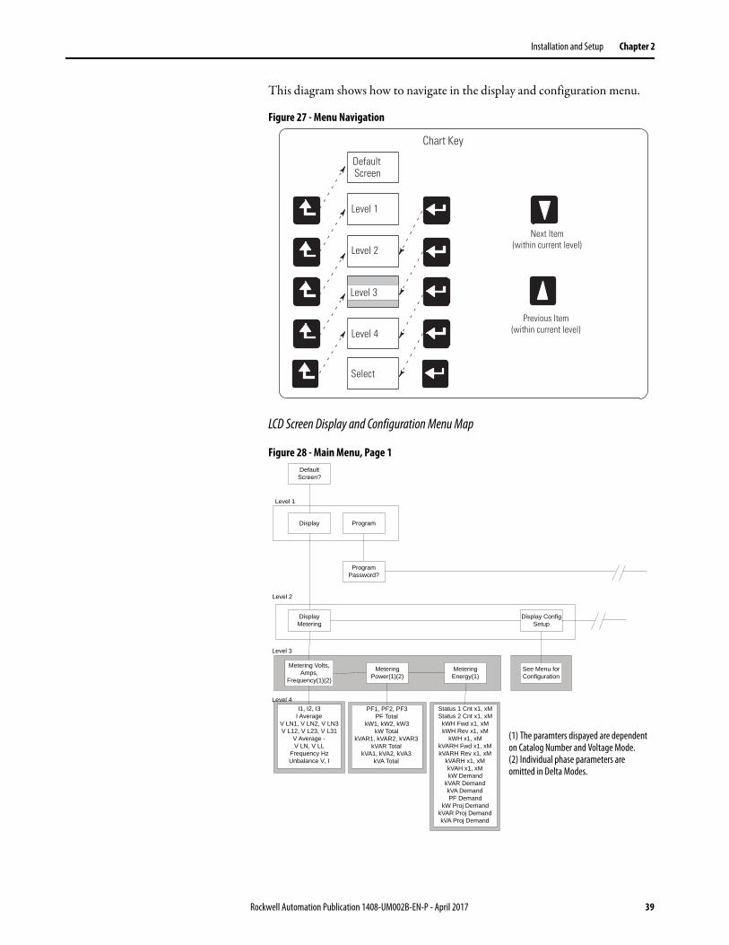
This diagram shows how to navigate in the display and configuration menu.
Figure 27 - Menu Navigation
LCD Screen Display and Configuration Menu Map
Figure 28 - Main Menu, Page 1
Chart Key
DefaultScreen
Select
Level 1
Level 2
Level 4
Level 3
Next Item(within current level)
Previous Item(within current level)
Default Screen?
Display Config Setup
Program
Program Password?
Display Metering
I1, I2, I3I Average
V LN1, V LN2, V LN3V L12, V L23, V L31
V Average -V LN, V LL
Frequency HzUnbalance V, I
Display
Metering Volts, Amps,
Frequency(1)(2)
See Menu for Configuration
Metering Power(1)(2)
Level 1
Level 2
Level 3
PF1, PF2, PF3PF Total
kW1, kW2, kW3kW Total
kVAR1, kVAR2, kVAR3kVAR Total
kVA1, kVA2, kVA3kVA Total
Metering Energy(1)
Status 1 Cnt x1, xMStatus 2 Cnt x1, xM
kWH Fwd x1, xMkWH Rev x1, xM
kWH x1, xMkVARH Fwd x1, xMkVARH Rev x1, xM
kVARH x1, xMkVAH x1, xMkW Demand
kVAR DemandkVA DemandPF Demand
kW Proj DemandkVAR Proj DemandkVA Proj Demand
Level 4
(1) The paramters dispayed are dependent on Catalog Number and Voltage Mode.(2) Individual phase parameters are omitted in Delta Modes.
Rockwell Automation Publication 1408-UM002B-EN-P - April 2017 39
Chapter 2 Installation and Setup
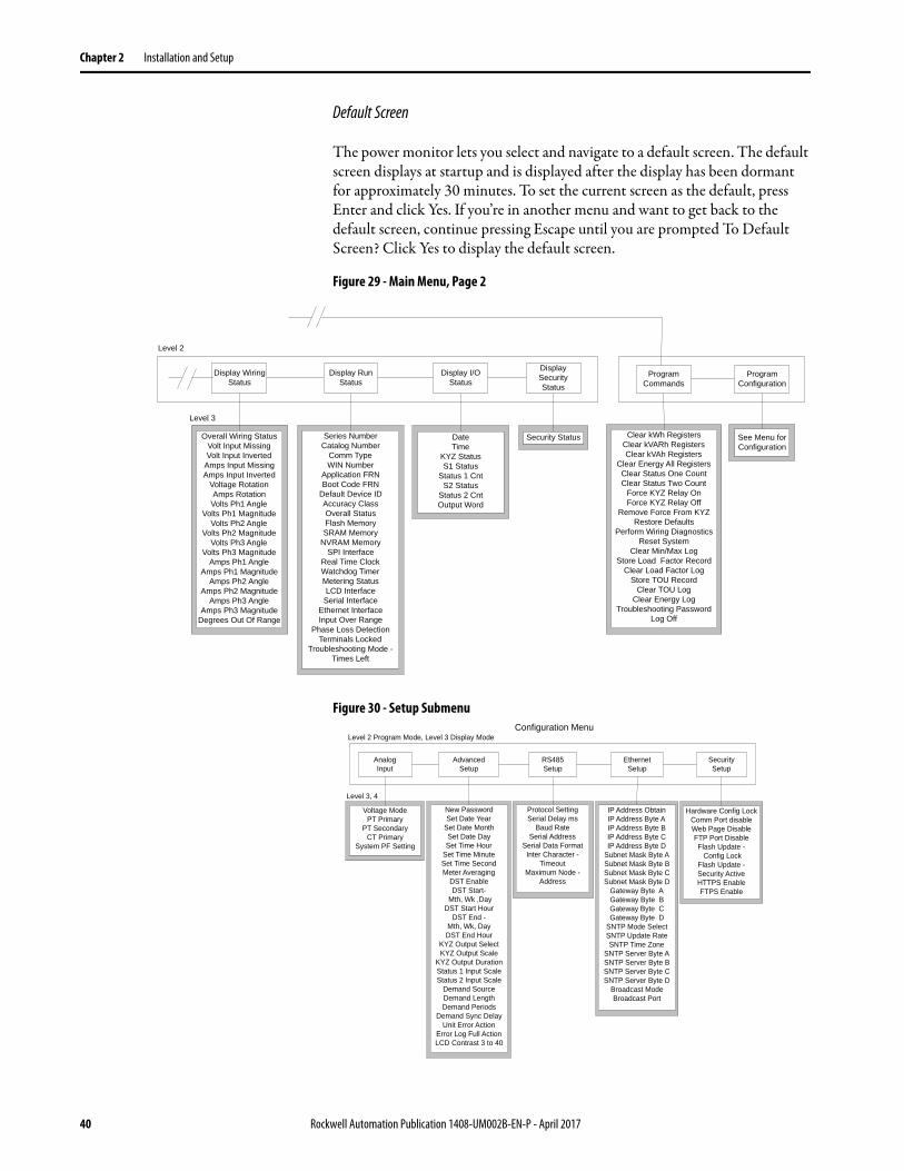
Default Screen
The power monitor lets you select and navigate to a default screen. The default screen displays at startup and is displayed after the display has been dormant for approximately 30 minutes. To set the current screen as the default, press Enter and click Yes. If you’re in another menu and want to get back to the default screen, continue pressing Escape until you are prompted To Default Screen? Click Yes to display the default screen.
Figure 29 - Main Menu, Page 2
Figure 30 - Setup Submenu
Display Run Status
Level 2
Series NumberCatalog Number
Comm TypeWIN Number
Application FRNBoot Code FRN
Default Device IDAccuracy ClassOverall StatusFlash MemorySRAM Memory
NVRAM MemorySPI Interface
Real Time ClockWatchdog TimerMetering StatusLCD InterfaceSerial Interface
Ethernet InterfaceInput Over Range
Phase Loss DetectionTerminals Locked
Troubleshooting Mode - Times Left
Display I/O Status
DateTime
KYZ StatusS1 Status
Status 1 CntS2 Status
Status 2 CntOutput Word
Program Commands
Program Configuration
See Menu for Configuration
Clear kWh RegistersClear kVARh RegistersClear kVAh Registers
Clear Energy All RegistersClear Status One CountClear Status Two Count
Force KYZ Relay OnForce KYZ Relay Off
Remove Force From KYZRestore Defaults
Perform Wiring DiagnosticsReset System
Clear Min/Max LogStore Load Factor Record
Clear Load Factor LogStore TOU Record
Clear TOU LogClear Energy Log
Troubleshooting PasswordLog Off
Level 3
Overall Wiring StatusVolt Input MissingVolt Input Inverted
Amps Input MissingAmps Input Inverted
Voltage RotationAmps Rotation
Volts Ph1 AngleVolts Ph1 Magnitude
Volts Ph2 AngleVolts Ph2 Magnitude
Volts Ph3 AngleVolts Ph3 Magnitude
Amps Ph1 AngleAmps Ph1 Magnitude
Amps Ph2 AngleAmps Ph2 Magnitude
Amps Ph3 AngleAmps Ph3 Magnitude
Degrees Out Of Range
Display Wiring Status
Display Security Status
Security Status
AnalogInput
Level 2 Program Mode, Level 3 Display ModeConfiguration Menu
Voltage ModePT Primary
PT SecondaryCT Primary
System PF Setting
Level 3, 4
AdvancedSetup
New PasswordSet Date Year
Set Date MonthSet Date DaySet Time Hour
Set Time MinuteSet Time SecondMeter Averaging
DST EnableDST Start-
Mth, Wk ,DayDST Start Hour
DST End -Mth, Wk, DayDST End Hour
KYZ Output SelectKYZ Output Scale
KYZ Output DurationStatus 1 Input ScaleStatus 2 Input Scale
Demand SourceDemand LengthDemand Periods
Demand Sync DelayUnit Error Action
Error Log Full ActionLCD Contrast 3 to 40
RS485Setup
Protocol SettingSerial Delay ms
Baud RateSerial Address
Serial Data FormatInter Character -
TimeoutMaximum Node -
Address
IP Address ObtainIP Address Byte AIP Address Byte BIP Address Byte CIP Address Byte D
Subnet Mask Byte ASubnet Mask Byte BSubnet Mask Byte CSubnet Mask Byte D
Gateway Byte AGateway Byte BGateway Byte CGateway Byte D
SNTP Mode SelectSNTP Update RateSNTP Time Zone
SNTP Server Byte ASNTP Server Byte BSNTP Server Byte CSNTP Server Byte D
Broadcast ModeBroadcast Port
EthernetSetup
Hardware Config LockComm Port disableWeb Page DisableFTP Port DisableFlash Update - Config Lock
Flash Update -Security ActiveHTTPS EnableFTPS Enable
SecuritySetup
40 Rockwell Automation Publication 1408-UM002B-EN-P - April 2017

Installation and Setup Chapter 2
Edit a Parameter
To edit a parameter, do the following:• Press <up> or <down> to change the highlighted digit.• Press <up> and <down> together to move the highlight cursor one
place to the left, and press <up> or <down> to set the selected digit’s value.
Continue in the same way until the correct value is entered then press <enter> when done.
Setup Example
This example steps through setting the unit date to demonstrate use of the display and buttons to navigate through the setup menu and make changes to parameters.
1. Navigate to the initial screen.
The screen shown is the top level screen. If it is not present, press <escape> until it appears.
If you press <escape> once too often, the To Default Screen? message appears. Press <escape> once more if this occurs.
2. Press <enter> and this screen appears.
PowerMonitor 1000RS-485 STATUS
RX TX Mod Net Power And Energy Management Solutions
PowerMonitor 1000RS-485 STATUS
RX TX Mod Net Display
Rockwell Automation Publication 1408-UM002B-EN-P - April 2017 41

Chapter 2 Installation and Setup
3. Press <up> or <down> once.
Program appears in the display. Press <enter>.
4. Press <enter> if the password has not been changed from the default (0000).
If the password has been changed, then enter the correct password.
When the correct password is entered, Program Setup appears in the display. The power monitor is now in Program mode.
If an incorrect password is entered, Invalid Password appears. Press any button to try again.
5. Press <enter>.
Analog Input appears in the display. Press <down>.
PowerMonitor 1000RS-485 STATUS
RX TX Mod Net Password 0000
PowerMonitor 1000RS-485 STATUS
RX TX Mod Net Program Setup
PowerMonitor 1000RS-485 STATUS
RX TX Mod Net Advanced Setup
42 Rockwell Automation Publication 1408-UM002B-EN-P - April 2017

Installation and Setup Chapter 2
6. With Advanced Setup displayed, press <enter>, then press <down> until Set Date Year appears.
7. Press <enter> to change the value of the year.
The power monitor is now in Edit mode, indicated by the presence of the highlight cursor. Change the year value and press <enter> to save it or <escape> to discard changes.
See Edit a Parameter on page 41 if you need help with this.
8. Select the next item in the configuration menu by pressing <down>.
Set the month in the same way.
Continue setting the remaining parameters in the same way.• Navigate to the top menu display• <enter> then <down> then <enter> to access the password screen• Enter the correct password to access Program mode• Navigate to the desired menu using <enter>, <up> and <down>• <enter> selects a parameter for editing• <up> or <down> increments or decrements the value of the highlighted
digit• <up> and <down> together move the highlight cursor• <enter> saves your changes; <escape> discards them• <escape> several times to the top menu to access Display mode
PowerMonitor 1000RS-485 STATUS
RX TX Mod Net Set DateYear2008
PowerMonitor 1000RS-485 STATUS
RX TX Mod Net
Set DateYear2005
Rockwell Automation Publication 1408-UM002B-EN-P - April 2017 43

Chapter 2 Installation and Setup
View Data with the Display
You can also view power monitor wiring diagnostics, metering, status and setup data using the display. To view data, select Display (instead of Setup) from the top menu and navigate through the menus as in the setup example. Press <enter> and <escape> to navigate into and out of submenus and <up> and <down> to select items within a submenu. Display mode does not permit you to change any parameter. Metering data available depends on the model of your power monitor.
Use Terminal Emulation Software for Setup
The PowerMonitor 1000 unit can be set up by using the RS-485 port for ASCII communication with terminal emulation software. HyperTerminal is no longer included with the Microsoft Windows operating system, however, a number of terminal emulation software options are available. The steps described here use PuTTY software, an open-source application that can be downloaded and used at no charge. Other terminal emulation software, such as HyperTerminal Private Edition and TeraTerm, can also be used.
Browse this link for more information or to download PuTTY software: http://www.chiark.greenend.org.uk/~sgtatham/putty/
Follow these steps to use PuTTY software for setup. If you use a different software, the steps to follow can be different.
1. Connect the unit to your computer with a serial cable or adapter.
See RS-485 Point-to-point Typical Wiring on page 32. If you use an RS-485 adapter that installs a virtual COM port, open Device Manager to determine the port assignment.
44 Rockwell Automation Publication 1408-UM002B-EN-P - April 2017

Installation and Setup Chapter 2
2. Launch PuTTY software.
3. When the software loads, select the following in the Session page:• Connection type: Serial• Serial line: COM1, another available port, or the virtual port
assigned by your communication adapter• Connection speed: 38400
Rockwell Automation Publication 1408-UM002B-EN-P - April 2017 45

Chapter 2 Installation and Setup
4. Select the Keyboard page and make the following change.
The Backspace key: Control-H
5. Select Serial and make the following changes:• Data bits: 8• Stop bits: 1• Parity: None
• Flow control: None
TIP If the port has been used for DH-485 communication, set Parity to Even.
46 Rockwell Automation Publication 1408-UM002B-EN-P - April 2017
Installation and Setup Chapter 2
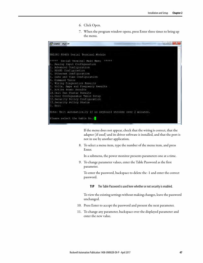
6. Click Open.
7. When the program window opens, press Enter three times to bring up the menu.
If the menu does not appear, check that the wiring is correct, that the adapter (if used) and its driver software is installed, and that the port is not in use by another application.
8. To select a menu item, type the number of the menu item, and press Enter.
In a submenu, the power monitor presents parameters one at a time.
9. To change parameter values, enter the Table Password as the first parameter.
To enter the password, backspace to delete the -1 and enter the correct password.
To view the existing settings without making changes, leave the password unchanged.
10. Press Enter to accept the password and present the next parameter.
11. To change any parameter, backspace over the displayed parameter and enter the new value.
TIP The Table Password is used here whether or not security is enabled.
Rockwell Automation Publication 1408-UM002B-EN-P - April 2017 47

Chapter 2 Installation and Setup
12. Press Enter to save and move to the next parameter.
The software displays ‘Write operation finished successfully’ after the last parameter is entered. This indicates the setup parameters are written to the power monitor. Other messages that are displayed include the following:• ‘Write error occurs with element 0’ - indicates that the correct Table
Password was not entered• ‘Write error occurs with element n’ - indicates that the value entered
for parameter n is outside the acceptable range of values
After the message, the prompt appears:‘Edit… Configuration Table again?‘Type Y for more editing, otherwise type any other key to exit.: N’
13. Type Y and press Enter to review or edit the selected setup parameters, or press Enter to return to the main setup menu.
The terminal session exits the setup menu after two minutes of inactivity, and displays ‘Quit RS485 Serial Terminal Mode’.
14. To resume, press Enter three times.
15. To save the PuTTY connection to the PowerMonitor 1000 unit, select Change Settings … from the PuTTY menu and save the setup in the Session page.
48 Rockwell Automation Publication 1408-UM002B-EN-P - April 2017

Installation and Setup Chapter 2
Use Communication to Set Up
You can set up the unit by using a programmable controller with user logic to write configuration tables using explicit messaging. Refer to the section on Explicit Messaging on page 87, for detailed information on configuring the unit through communication with a programmable controller or custom software application.
Set-up Menus
Whichever set-up method you select, set-up parameters are organized in several set-up menus.
• Analog input setup• Advanced setup• RS-485 communication setup• Optional Ethernet network communication setup• Date and time setup• User Configurable Table Setup (except BC3 model)• Security Policy Configuration
Rockwell Automation Publication 1408-UM002B-EN-P - April 2017 49

Chapter 2 Installation and Setup
Notes:
50 Rockwell Automation Publication 1408-UM002B-EN-P - April 2017

Chapter 3
PowerMonitor 1000 Unit Features
This section describes in detail the functions of the power monitor. Each function includes information on set-up menus and parameters used to control its operation.
Security The PowerMonitor™ 1000 Series B product operates in two modes. In Operational mode, the product performs the everyday functions, but setup changes are not permitted. In Administrative mode, the product continues to perform as though in Operational mode, however, changes in setup and security policy are permitted, and commands can be executed.
Administrative mode access is governed by a user-configured security policy. A Policy Holder, defined during initial commissioning of the product, administers security policy. Refer to First Run Web Page on page 15, for more details.
Security Configuration Selections
The Policy Holder can create security user logins and make selections that control administrative mode access.
• The Policy Holder can disable Web Page Access Security and CIP Explicit Message Security (disabled is the default setting for these parameters). In this case, the PowerMonitor 1000 unit operates the same as Series A units, by using a Table Password to enable changes to setup or execute commands.
If the Table Password is active, there are two ways to gain write access:– An entire table including a valid Table Password is written.– A valid Table Password is written to the Single element password
write table, which then enables single element writes until 30 minutes elapses without a write.
IMPORTANT The security policy does not apply to the LCD display and keypad, nor to the RS-485 communication options, including DF-1, DH-485, Modbus RTU, and ASCII (terminal emulation). These methods retain the use of the Table Password for protecting against unauthorized changes to the setup.
Rockwell Automation Publication 1408-UM002B-EN-P - April 2017 51

Chapter 3 PowerMonitor 1000 Unit Features
• The Policy Holder can enable Web Page Security. In this case, the Policy Holder or an Admin user must be logged-in to change configuration or execute commands by using the web page. The Table Password is no longer active, its entry field in web pages is disabled (grayed-out) and its value is ignored by the product.
• The Policy Holder can enable CIP Explicit Message Security. In this case, a controller or other CIP or Modbus/TCP client must log in to change configuration or execute commands by writing to data tables. The Table Password is no longer active, and when it is written to the unit, its value is ignored. This option applies to both EtherNet/IP and Modbus/TCP communication using the Ethernet port.
• The security policy restricts only write access to the power monitor configuration and command tables. No login is required by a user or an application to read data, including data logs.
Security User Types
The Policy Holder can establish user logins. Two User Types are available:• Admin - When Web Page Security is enabled, the Admin user type
permits you to log in by using the web interface. After you log in, you can change the unit setup, edit the security policy, create, delete and edit users, and issue commands for the unit to process.
• Application - When CIP Explicit Message Security is enabled, the Application user type permits an application, such as a programmable controller or operator terminal, to write data using explicit messages to change the unit setup and issue commands.
At most, one Admin user and one Application user can be logged in at the same time. Each user type has access to change the unit setup and execute commands.
52 Rockwell Automation Publication 1408-UM002B-EN-P - April 2017

PowerMonitor 1000 Unit Features Chapter 3
Managing Users
The Policy Holder can use the web Security page to create additional Admin or Application users while logged in. Once an Admin user is created, the Admin user can also create additional users of either user type. User names and passwords are ASCII strings with a maximum length of 32 characters.
The Policy Holder is created in the first run web page on initial commissioning of the unit and can be modified but cannot be deleted. To modify the Policy Holder credentials, follow these steps.
1. Log in as the Policy Holder (1)and click Change Policy Holder (2).
2. To change the name, email address, and phone number (3), type in the field.
3. To edit the Policy Holder user name and password, check Change Credentials (4). a. Enter a new User name.b. Enter a new Password.c. Confirm the password.
4. Click Apply Changes (5) when done.
IMPORTANT The user name and password can only be changed if Change Credentials is checked.
IMPORTANT If the Policy Holder credentials (user name and password) are lost or forgotten, the unit must be reset to factory defaults if Policy Holder access is required.
1
2 4
5
3
Rockwell Automation Publication 1408-UM002B-EN-P - April 2017 53
Chapter 3 PowerMonitor 1000 Unit Features
Logging In
With Web Page Security enabled, to edit the unit setup or execute commands, an Admin user or the Policy Holder must log in. An Application user is not permitted to log in to the web page.
1. Log in by using one of two ways:• Click the Log in link in the web page header, enter the user name,
password, and click Log In.• Open the Security folder, click the Security link, enter the user name,
password, and click Log In.
2. With CIP Explicit Message Security enabled, to edit the unit setup or execute commands, an application must write the user name (with NULL characters appended to establish a 32-character string length) to the Security User Name data table.
3. Then, within 30 seconds, write the 32-bit password (also with NULL characters appended to establish a 32-character string length) to the Security Password data table to log in.
Only an Application type user can use this method.
Logging Out
There are two ways to log out from the web page:• Click the Log out link in the web page header.• Open the Security folder, click the Security link, and click Log Out.
An application can log out by writing a value of 8 to Command Word 2 in the Command data table.
Users and applications are automatically logged out after 30 minutes without write activity.
TIP An example of writing the application user name and password for EtherNet/IP is provided in Chapter 4, Explicit Messaging.
54 Rockwell Automation Publication 1408-UM002B-EN-P - April 2017

PowerMonitor 1000 Unit Features Chapter 3
Additional Security Policy Configuration
A number of additional security policy options are available and can be accessed in the web Security Policy Configuration page or the Security Policy Configuration data table.
Table 7 - Security Policy Configuration
Parameter Description Default Range User Setting
Hardware Configuration Lock
Defines behavior when Configuration Lock jumper is applied between terminals CF1 and CF20 = Lock Analog Input configuration, energy configuration parameters, security policy configuration and command word 1 parameters including unit reset.1 = Lock Analog Input configuration, energy configuration parameters, security policy configuration and command word 1 parameters including unit reset, lock Ethernet configuration.
0 0…1
Communication Port Disable
0 = All available communication ports enabled1 = Ethernet port disabled2 = RS485 port disabled
0 0…2
Web Page Disable 0 = Enable web page access1 = Disable web page access
0 0…1
FTP Port Disable 0 = Enable ftp port access1 = Disable ftp port access
0 0…1
Flash Update Disable Configuration Lock
0 = Allow firmware flash update when configuration is locked by hardware.1 = Disable firmware flash update when configuration is locked by hardware.
0 0…1
Flash Update Disable Security Active
0 = Allow firmware flash update when security is enabled.1 = Disable firmware flash update when security for CIP is enabled.2 = Disable firmware flash update when security for web page is enabled.IMPORTANT: Under setting 2, the CIP Reset Service is active and can still be used to reset the PowerMonitor 1000 unit. Enable security for CIP to block CIP Reset Service Messages.3 = Disable firmware flash update when security for CIP or web page is enabled.IMPORTANT: If Security is enabled and the Admin Login source IP address and the Flash Source IP address are the same, then Flash Update is allowed.
0 0…3
HTTPS Enable(1) 0 = HTTPS disable.1 = HTTPS enable.
0 0…1
FTPS Enable(2) 0 = FTPS disable.1 = FTPS enable.
0 0…1
(1) If enabled, you must use a browser capable of supporting SSL 3.0 (TLS 1.0), and enter the unit IP address with an ‘https://’ prefix.
(2) If enabled, you must use an ftp client capable of supporting SSL 3.0 (TLS 1.0).
Rockwell Automation Publication 1408-UM002B-EN-P - April 2017 55

Chapter 3 PowerMonitor 1000 Unit Features
Analog Input Setup This feature applies to all models.
Setup
The power monitor calculates metering results based on scaled voltage and current inputs. Setting up the analog inputs is necessary to obtain accurate, properly scaled metering results.
Related Functions• Wiring diagnostics• Configuration lock
Wiring Diagnostics The power monitor performs wiring diagnostics on command to detect and report wiring errors. Wiring diagnostics operate in any wiring mode except Demo and 1PT 1CT modes, provided that measured current is at least 10% of the CT primary parameter in Analog Setup. You can select from three ranges of system power factor to improve wiring diagnostics accuracy.
This function applies to all models. The BC3 model provides a limited results set.
Table 8 - Analog Input Setup
Parameter Description Range Default User Setting
Voltage mode Must match the external electrical system and how it is wired to the PowerMonitor voltage and current input terminals. Refer to the wiring diagrams.0 = Direct Delta 1 = Open Delta 2 = Wye3 = Split Phase4 = Demo, simulated results5 = 1PT1CT-LL6 = 1PT1CT-LN
0…6 2
PT primary The primary value of the PT ratio (Pri:Sec) indicating the nominal voltage present at the high-end of the transformer. For direct connect, set the PT ratio to any valid 1:1 ratio (for example, 480:480).
1.00… 50,000 480
PT secondary The secondary value of the PT ratio (Pri:Sec) indicating the nominal voltage present at the low-end of the transformer.
1…600 480
CT primary The primary value of the CT ratio (Pri:5) indicating the nominal current present at the high-end of the transformer. The nominal CT rated current is 5 A.
5…50,000 5
System PF setting Select range corresponding to expected power factor. 0 = Lead (-97…89)1 = High (-85…98)2 = Low (-52…-95)
2 = Low
56 Rockwell Automation Publication 1408-UM002B-EN-P - April 2017

PowerMonitor 1000 Unit Features Chapter 3
Diagnostic Parameters
When a Perform wiring diagnostics command is given, the power monitor calculates and returns the results. To reduce the likelihood of erroneous or misleading wiring diagnostic data, interim results of multiple tests must agree before results are displayed. Wiring diagnostic results return to their default status approximately five minutes after the command is issued.
Wiring status:• Pass - system wiring is correct for the voltage mode and power factor
selections.• Failed - system wiring is incorrect. Refer to voltage and current input
status for additional information.• Input Low - measured current is below 10% of full scale.• Disabled - the power monitor is in Demo or 1PT 1CT wiring mode.• Waiting Command - five minutes have elapsed since the most recent
command.• Out of Range - measured phase angles are outside the range of the
selected system power factor.• Voltage or current input missing (input below the metering threshold)
or inverted (reverse polarity, 180 degrees out of phase)– -1 — Test not run; see wiring status for reason.– 0 — Pass, all inputs present / correct polarity.– 1 — Phase 1 missing / inverted.– 2 — Phase 2 missing / inverted.– 3 — Phase 3 missing / inverted.– 12 — Phase 1 and 2 missing / inverted.– 13 — Phase 1 and 3 missing / inverted.– 23 — Phase 2 and 3 missing / inverted.– 123 — All 3 phases missing / inverted.
• Voltage rotation– -1 — Test not run; see wiring status for reason.– 123 — Forward phase rotation (ABC).– 132 — Reverse phase rotation (ACB).– 4 — Invalid phase rotation (2 inputs wired with same phase).
• Current rotation, referenced to voltage Phase 1– -1 — Test not run; see wiring status for reason.– 123 — Forward rotation (ABC).– 231 — Forward rotation, 120 degrees displaced (BCA).– 312 — Forward rotation, 240 degrees displaced (CAB).– 132 — Reverse rotation (ACB).– 213 — Reverse rotation, 120 degrees displaced (BAC).– 321 — Reverse rotation, 240 degrees displaced (CBA).– 4 — Invalid phase rotation (2 inputs wired with same phase).
Rockwell Automation Publication 1408-UM002B-EN-P - April 2017 57

Chapter 3 PowerMonitor 1000 Unit Features
Forward phase rotation is not required to pass wiring diagnostics. Before changing wiring connections, refer to both the voltage / current rotation and voltage/current inverted status to select the correct analog input.
Magnitude and Phase Angle
The power monitor continually returns voltage and current magnitude and phase angle data. This data can be used to construct a phasor diagram, and in addition to the diagnostics parameters, to troubleshoot wiring issues. The following exceptions apply.
• Magnitude data is not returned by the BC3 model• Current phase angle 2 always returns 0 in open-delta wiring mode
Phase angles are consistent with the four-quadrant power metering diagram.
See Power Metering on page 65.
Setup
Basic analog setup is required. In addition, a system power factor must be selected. The ranges are as follows:
• Low (52…95% lag, default setting)• High (85 lag …98% lead)• Leading (97 lag …89% lead)
Results
Wiring diagnostics results can be viewed by using the following methods:• Web interface• LCD screen (except for BC3 model)• Communication• RS-485 terminal emulation software
Commands• Perform wiring diagnostics• Test wiring connections (LCD screen menu)
TIP The Troubleshooting mode of the power monitor lets you view magnitude data.See Troubleshooting Mode on page 59.
58 Rockwell Automation Publication 1408-UM002B-EN-P - April 2017

PowerMonitor 1000 Unit Features Chapter 3
Troubleshooting Mode Troubleshooting mode lets you enter a password-protected command that makes available all metered parameters for troubleshooting purposes. Troubleshooting mode does not change the data log support.
RS-485 Communication This function applies to all models.
Setup
Your power monitor is set up to communicate via its RS-485 port using a default set of parameters when you first apply power.
DH-485 protocol is supported in firmware FRN 2.0 and higher. If DH-485 is selected, the data format is automatically set to 8 / 1 / even. Recommended data rates for DH-485 are 9600 and 19.2k.
Error checking method is Cyclic Redundancy Check (CRC). All devices on a multi-drop RS-485 network must be set at the same data rate and each must be assigned a unique network address.
ASCII protocol used with terminal emulation software is always available, regardless of the protocol selection.
TIP This mode does not apply to the 1408-EM3 because this meter already has all of the parameters available.
Table 9 - RS-485 Communication Setup
Parameter Description Range Default User Setting
Protocol Setting DF1 Half-duplex SlaveDF1 Full-duplexModbus RTU SlaveAuto SenseDH485
DF1 Full-duplex
Delay(1) Time between receiving a request and transmitting a response
0…75 ms 10 ms
Baud Rate Communication bit rate per second 1200, 2400, 4800, 9600(2), 19.2k(2), 38.4k, 57.6k
38.4k
RS-485 Address Uniquely identifies the power monitor on a multi-drop network
1…2470…31(3)
Unit ID number
Data Format Data bits / stop bits / parity 8 / 1 / none8 / 1 / even(3)
8 / 1 / odd
8 / 1 / none
Inter Character Timeout(1) Minimum delay between characters that indicates the end of a Modbus message packet
0…6553 ms 0 = 3.5 character times
Max Node Address(3) 1…31 31
(1) Delay, Inter Character Timeout parameters have no effect on DH485 protocol
(2) The baud-rate setting for DH485 must be 9600 or 19.2 k
(3) DH485
Rockwell Automation Publication 1408-UM002B-EN-P - April 2017 59

Chapter 3 PowerMonitor 1000 Unit Features
Optional Ethernet Network Communication
The power monitor supports simultaneous operation of the optional Ethernet network and serial ports.
This feature applies to all models with catalog numbers ending in -ENT.
The Ethernet network port supports 10 Mbps data rate, half-duplex.
Setup
The Ethernet network port is set up with a default IP address and gateway using a common auto-configuration addressing scheme. The default address simplifies the task of making an initial connection to the unit from a personal computer with a compatible Class B IP address.
The power monitor operates with a fixed IP address that uniquely identifies it on the network. An IP address of 255.255.255.255 is not permitted. We recommend that you set up the unit with fixed Ethernet addressing, however, the unit does support DHCP auto-addressing.
Table 10 - Ethernet Network Communication Setup
Parameter Description Range Default User Setting
IP address bytes 1…4 Unit IP address in format aaa.bbb.ccc.ddd 0…255 192.168.254.x (x is the unit’s ID)
Subnet mask bytes 1…4 Subnet mask in format aaa.bbb.ccc.ddd 0…255 255.255.255.0
Gateway IP address bytes 1…4 Gateway IP address in format aaa.bbb.ccc.ddd 0…255 192.168.254.1
SNTP setup See Date and Time Functions setup. Includes:SNTP modeUpdate intervalTime zoneTime server IP address
IMPORTANT The IP address for your power monitor must not conflict with the IP address of any other device on the network. Contact your network administrator to obtain a unique IP address, subnet mask, and default gateway address for your unit.
60 Rockwell Automation Publication 1408-UM002B-EN-P - April 2017
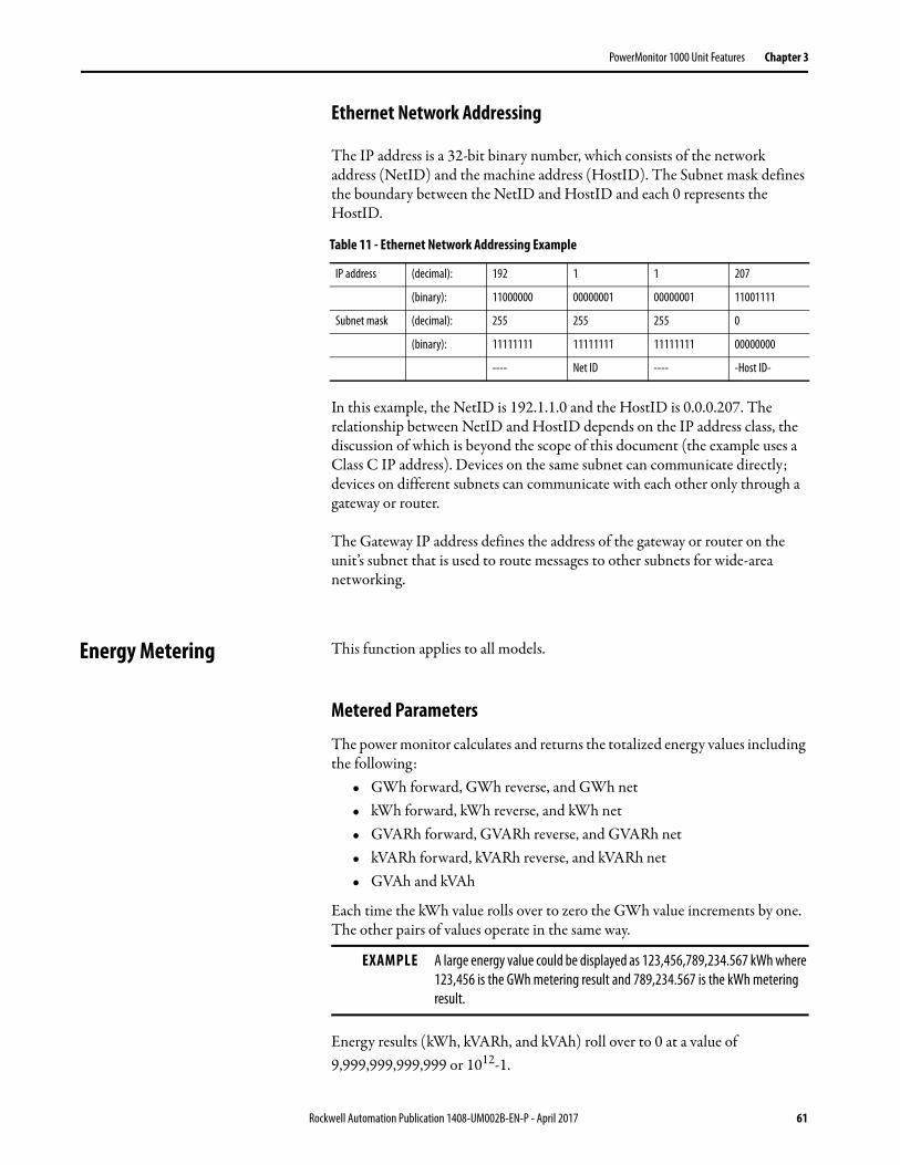
PowerMonitor 1000 Unit Features Chapter 3
Ethernet Network Addressing
The IP address is a 32-bit binary number, which consists of the network address (NetID) and the machine address (HostID). The Subnet mask defines the boundary between the NetID and HostID and each 0 represents the HostID.
In this example, the NetID is 192.1.1.0 and the HostID is 0.0.0.207. The relationship between NetID and HostID depends on the IP address class, the discussion of which is beyond the scope of this document (the example uses a Class C IP address). Devices on the same subnet can communicate directly; devices on different subnets can communicate with each other only through a gateway or router.
The Gateway IP address defines the address of the gateway or router on the unit’s subnet that is used to route messages to other subnets for wide-area networking.
Energy Metering This function applies to all models.
Metered Parameters
The power monitor calculates and returns the totalized energy values including the following:
• GWh forward, GWh reverse, and GWh net• kWh forward, kWh reverse, and kWh net• GVARh forward, GVARh reverse, and GVARh net• kVARh forward, kVARh reverse, and kVARh net• GVAh and kVAh
Each time the kWh value rolls over to zero the GWh value increments by one. The other pairs of values operate in the same way.
Energy results (kWh, kVARh, and kVAh) roll over to 0 at a value of9,999,999,999,999 or 1012-1.
Table 11 - Ethernet Network Addressing Example
IP address (decimal): 192 1 1 207
(binary): 11000000 00000001 00000001 11001111
Subnet mask (decimal): 255 255 255 0
(binary): 11111111 11111111 11111111 00000000
---- Net ID ---- -Host ID-
EXAMPLE A large energy value could be displayed as 123,456,789,234.567 kWh where 123,456 is the GWh metering result and 789,234.567 is the kWh metering result.
Rockwell Automation Publication 1408-UM002B-EN-P - April 2017 61

Chapter 3 PowerMonitor 1000 Unit Features
Setup
Only basic analog input setup is required for energy metering.
Results
Energy metering results can be viewed by using the following methods:• Web interface• LCD screen (except BC3 model)• Communication
Energy results are not available via terminal emulation software.
Commands
The following commands are supported by the power monitor:• Set GWh/kWh register• Set GVARh/kVARh register• Set GVAh/kVAh register• Clear all energy registers
Related Functions• KYZ output (except BC3 model)• Energy log• Configuration lock
62 Rockwell Automation Publication 1408-UM002B-EN-P - April 2017

PowerMonitor 1000 Unit Features Chapter 3
Demand Metering Demand is an electric power term that expresses the average energy usage over a period of time. The power monitor can be configured to measure demand using a fixed demand period or a sliding window. The demand period can be timed internally, synchronized to an external demand end-of-interval contact connected to the S2 status input, or synchronized using communication.
This function applies to catalog number 1408-EM3.
Metered Parameters
The power monitor calculates and returns the following demand values:• Real power demand, kW• Reactive power demand, kVAR• Apparent power demand, kVA• Demand power factor, percent lagging (-) or leading (+)• Projected kW, kVAR, and kVA demand• Demand interval elapsed time, minutes
Projected demand calculates a linear projection of demand at the end of a demand interval.
Demand power factor is calculated using the following formula.
kW Demand / kVA Demand
Setup
Demand metering requires basic analog input setup as well as demand calculation setup. Basic demand set-up parameters are found in the Advanced Setup menu. Network demand synchronization is available on units connected to an Ethernet network. Network-demand synchronization set-up parameters are found in the Ethernet communication set-up menu.
Rockwell Automation Publication 1408-UM002B-EN-P - April 2017 63
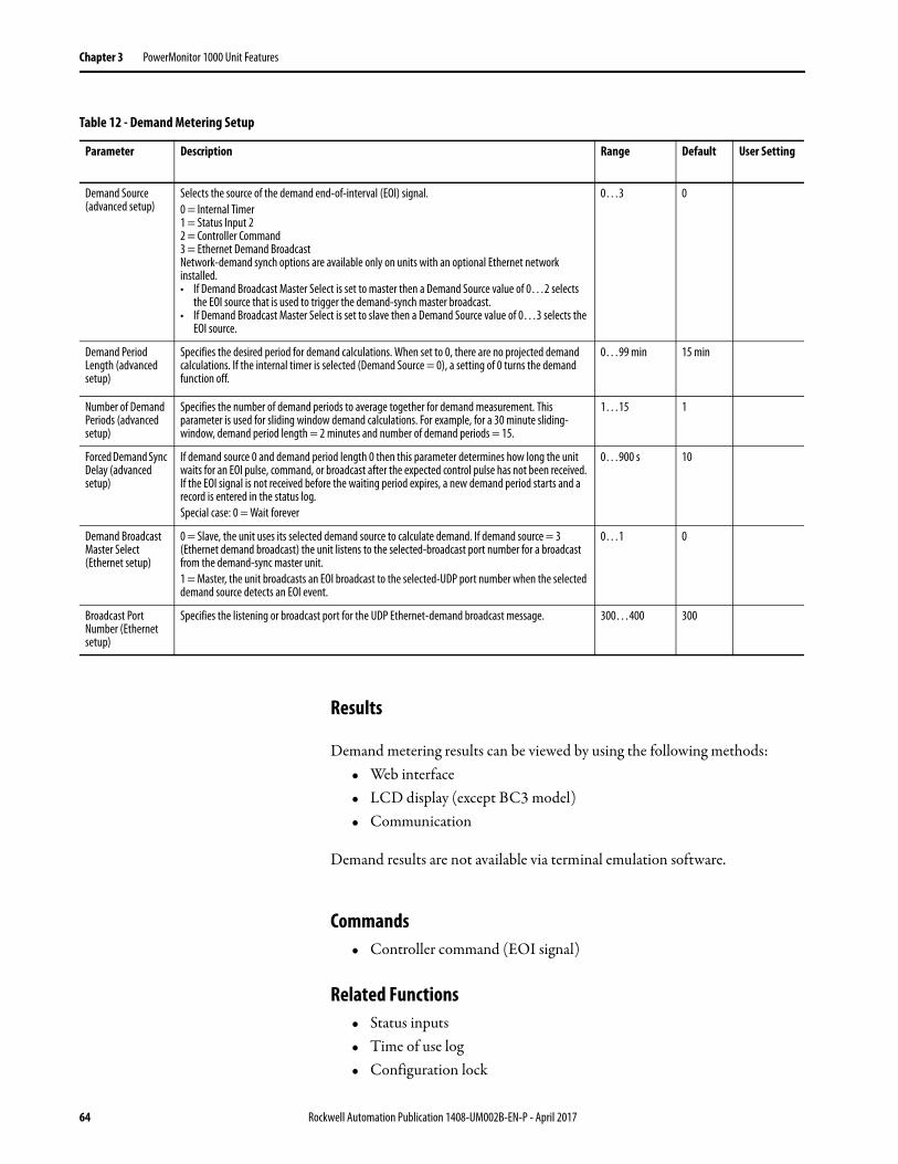
Chapter 3 PowerMonitor 1000 Unit Features
Results
Demand metering results can be viewed by using the following methods:• Web interface• LCD display (except BC3 model)• Communication
Demand results are not available via terminal emulation software.
Commands• Controller command (EOI signal)
Related Functions• Status inputs• Time of use log• Configuration lock
Table 12 - Demand Metering Setup
Parameter Description Range Default User Setting
Demand Source (advanced setup)
Selects the source of the demand end-of-interval (EOI) signal.0 = Internal Timer1 = Status Input 22 = Controller Command3 = Ethernet Demand BroadcastNetwork-demand synch options are available only on units with an optional Ethernet network installed.• If Demand Broadcast Master Select is set to master then a Demand Source value of 0…2 selects
the EOI source that is used to trigger the demand-synch master broadcast.• If Demand Broadcast Master Select is set to slave then a Demand Source value of 0…3 selects the
EOI source.
0…3 0
Demand Period Length (advanced setup)
Specifies the desired period for demand calculations. When set to 0, there are no projected demand calculations. If the internal timer is selected (Demand Source = 0), a setting of 0 turns the demand function off.
0…99 min 15 min
Number of Demand Periods (advanced setup)
Specifies the number of demand periods to average together for demand measurement. This parameter is used for sliding window demand calculations. For example, for a 30 minute sliding-window, demand period length = 2 minutes and number of demand periods = 15.
1…15 1
Forced Demand Sync Delay (advanced setup)
If demand source 0 and demand period length 0 then this parameter determines how long the unit waits for an EOI pulse, command, or broadcast after the expected control pulse has not been received. If the EOI signal is not received before the waiting period expires, a new demand period starts and a record is entered in the status log.Special case: 0 = Wait forever
0…900 s 10
Demand Broadcast Master Select (Ethernet setup)
0 = Slave, the unit uses its selected demand source to calculate demand. If demand source = 3 (Ethernet demand broadcast) the unit listens to the selected-broadcast port number for a broadcast from the demand-sync master unit.1 = Master, the unit broadcasts an EOI broadcast to the selected-UDP port number when the selected demand source detects an EOI event.
0…1 0
Broadcast Port Number (Ethernet setup)
Specifies the listening or broadcast port for the UDP Ethernet-demand broadcast message. 300…400 300
64 Rockwell Automation Publication 1408-UM002B-EN-P - April 2017

PowerMonitor 1000 Unit Features Chapter 3
Power Metering This function applies to all models.
Metered Parameters
The power monitor calculates and returns four-quadrant power measurements including these:
• L1, L2, L3 and Total True Power Factor, percent lagging (-) and leading (+)
• L1, L2, L3 and Total Real Power, kW• L1, L2, L3 and Total Reactive Power, kVAR• L1, L2, L3 and Total Apparent Power, kVA
Only total three-phase power results are provided when Direct Delta or Open Delta wiring modes are selected.
The Magnitude and Direction of Power Quantities chart indicates the relationship between the magnitude and direction of the power quantities and the numeric signs used by the power monitor.
Figure 31 - Magnitude and Direction of Power Quantities
Setup
Only basic analog-input setup is required for power metering.
II
III IV
I
90°
180°
270°
0°Pf = 100%+kW (import)kWH-F (forward)
(power factor lagging)(-)
Pf = 0+kVAR (import)kVARHR-F (forward)
(power factor leading)(+)
(power factor lagging)(-)
(power factor leading)(+)
Pf = 0-kVAR (export)kVARHR-R (reverse)
Pf = 100%-kW (export)kWH-R (reverse)
Rockwell Automation Publication 1408-UM002B-EN-P - April 2017 65

Chapter 3 PowerMonitor 1000 Unit Features
Results
Power metering results can be viewed by using the following methods:• Web interface• LCD screen (except BC3 model)• Communication• RS-485 terminal emulation software
Related Functions• Metering result averaging• Configuration lock
Voltage, Current, and Frequency Metering
This function applies to catalog numbers 1408-TS3 and 1408-EM3.
Metered Parameters
The power monitor calculates and returns voltage, current, and frequency measurements including these:
• L1, L2, L3, and Average Current, A• L1-N, L2-N, L3-N, and Average L-N Voltage, V• L1-L2, L2-L3, L3-L1, and Average L-L Voltage, V• Frequency• Percent Current Unbalance• Percent Voltage Unbalance
Line-to-neutral voltage results are not provided for Delta and Open Delta wiring modes.
Voltage and current unbalance are calculated according to the following formula.
Setup
Only basic analog-input setup is required for voltage, current, and frequency metering.
Maximum Deviation from Average 100×Average
----------------------------------------------------------------------------------------------------------
66 Rockwell Automation Publication 1408-UM002B-EN-P - April 2017
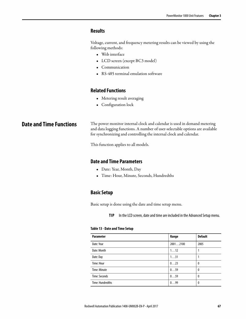
PowerMonitor 1000 Unit Features Chapter 3
Results
Voltage, current, and frequency metering results can be viewed by using the following methods:
• Web interface• LCD screen (except BC3 model)• Communication• RS-485 terminal emulation software
Related Functions• Metering result averaging• Configuration lock
Date and Time Functions The power monitor internal clock and calendar is used in demand metering and data logging functions. A number of user-selectable options are available for synchronizing and controlling the internal clock and calendar.
This function applies to all models.
Date and Time Parameters• Date: Year, Month, Day• Time: Hour, Minute, Seconds, Hundredths
Basic Setup
Basic setup is done using the date and time setup menu.
TIP In the LCD screen, date and time are included in the Advanced Setup menu.
Table 13 - Date and Time Setup
Parameter Range Default
Date: Year 2001…2100 2005
Date: Month 1…12 1
Date: Day 1…31 1
Time: Hour 0…23 0
Time: Minute 0…59 0
Time: Seconds 0…59 0
Time: Hundredths 0…99 0
Rockwell Automation Publication 1408-UM002B-EN-P - April 2017 67
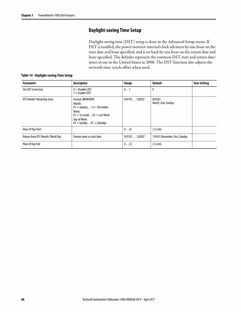
Chapter 3 PowerMonitor 1000 Unit Features
Daylight-saving Time Setup
Daylight-saving time (DST) setup is done in the Advanced Setup menu. If DST is enabled, the power monitor internal clock advances by one hour on the start date and hour specified, and is set back by one hour on the return date and hour specified. The defaults represent the common DST start and return date/times in use in the United States in 2006. The DST function also adjusts the network-time synch offset when used.
Table 14 - Daylight-saving Time Setup
Parameter Description Range Default User Setting
Use DST Correction 0 = Disables DST1 = Enables DST
0…1 0
DST Month/ Week/Day Start Format: MMWWDDMonth:01 = January…12 = DecemberWeek:01 = 1st week…05 = Last WeekDay of Week:01 = Sunday…07 = Saturday
010101… 120507 030201March, 2nd, Sunday
Hour of Day Start 0…23 2 (2 am)
Return from DST Month/ Week/Day Format same as start date 010101… 120507 110101 November, First, Sunday
Hour of Day End 0…23 2 (2 am)
68 Rockwell Automation Publication 1408-UM002B-EN-P - April 2017
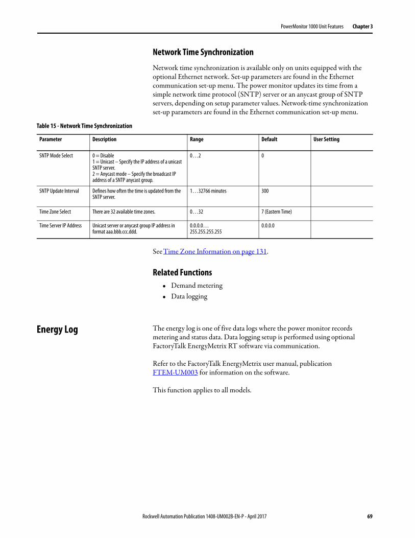
PowerMonitor 1000 Unit Features Chapter 3
Network Time Synchronization
Network time synchronization is available only on units equipped with the optional Ethernet network. Set-up parameters are found in the Ethernet communication set-up menu. The power monitor updates its time from a simple network time protocol (SNTP) server or an anycast group of SNTP servers, depending on setup parameter values. Network-time synchronization set-up parameters are found in the Ethernet communication set-up menu.
See Time Zone Information on page 131.
Related Functions• Demand metering• Data logging
Energy Log The energy log is one of five data logs where the power monitor records metering and status data. Data logging setup is performed using optional FactoryTalk EnergyMetrix RT software via communication.
Refer to the FactoryTalk EnergyMetrix user manual, publication FTEM-UM003 for information on the software.
This function applies to all models.
Table 15 - Network Time Synchronization
Parameter Description Range Default User Setting
SNTP Mode Select 0 = Disable1 = Unicast – Specify the IP address of a unicast SNTP server.2 = Anycast mode – Specify the broadcast IP address of a SNTP anycast group.
0…2 0
SNTP Update Interval Defines how often the time is updated from the SNTP server.
1…32766 minutes 300
Time Zone Select There are 32 available time zones. 0…32 7 (Eastern Time)
Time Server IP Address Unicast server or anycast group IP address in format aaa.bbb.ccc.ddd.
0.0.0.0…255.255.255.255
0.0.0.0
Rockwell Automation Publication 1408-UM002B-EN-P - April 2017 69

Chapter 3 PowerMonitor 1000 Unit Features
Logged Parameters
Energy log records contain a date/time stamp and the metering parameters listed.
Results
Energy log records can be accessed via communication or ftp. See the Energy Results data table, page 148 for the content and format of the logging results.
Commands• Clear energy log
Related Functions• Energy metering, Demand metering• Configuration lock
Table 16 - Included Parameters
Metering Parameter BC3 TS3 EM3
Status Input 1 Scaled Count • •
Status Input 2 Scaled Count • •
Real Energy Net, GWh / kWh • • •
Reactive Energy Net, GVARH / kVARh • • •
Apparent Energy Net, GVAh / kVAh • • •
Real Power Demand, kW •
Reactive Power Demand, kVAR •
Apparent Power Demand, kVA •
Demand PF, percent •
70 Rockwell Automation Publication 1408-UM002B-EN-P - April 2017

PowerMonitor 1000 Unit Features Chapter 3
Min/Max Log The power monitor records time-stamped minimum and maximum values for all real-time metering data (except for energy data).
This feature applies to all models.
Logged Parameters
The min/max log contains a record for each of the metering parameters listed in Table 17 along with a date/time stamp corresponding to the minimum and maximum value recorded.
Results
Min/max log records can be accessed via communication. See the Min/Max Log Results data table, page 159 for the content and format of the logging results.
Commands• Clear single min/max log record• Clear min/max log
Related Functions• Energy metering• Demand metering• Voltage, current and frequency metering• Power metering
Table 17 - Min/Max Log Record
Metering Parameter BC3 TS3 EM3
L1, L2, L3 and Average Current • •
L1-N, L2-N, L3-N and Average L-N Voltage • •
L1-L2, L2-L3, L3-L1 and Average L-L Voltage • •
Frequency • •
Percent Current Unbalance • •
Percent Voltage Unbalance • •
L1, L2, L3 and Total True Power Factor • • •
L1, L2, L3 and Total Real Power, kW • • •
L1, L2, L3 and Total Reactive Power, kVAR • • •
L1, L2, L3 and Total Apparent Power, kVA • • •
Real Power Demand, kW •
Reactive Power Demand, kVAR •
Apparent Power Demand, kVA •
Demand PF, percent •
Rockwell Automation Publication 1408-UM002B-EN-P - April 2017 71

Chapter 3 PowerMonitor 1000 Unit Features
Load Factor Log The power monitor maintains a 12-month record of demand and load factor. Load factor is average demand divided by peak demand and is a measure of load variability.
This function applies to catalog number 1408-EM3.
Logged Parameters
The load factor log consists of 13 records, an in-process record for the current month, and one record for the previous 12 months. The monthly records operate in a circular or FIFO fashion. On a user-selected day each month, the current record is pushed into the monthly record stack and cleared. Each record contains the following data:
• Real power demand, peak and average, kW• Real power load factor, percent• Reactive power demand, peak and average, kVAR• Reactive power load factor in percent• Apparent power demand, peak and average, kVA• Apparent power load factor in percent
Results
Load factor log records can be accessed via communication. See the Load Factor Log Results data table, page 159 for the content and format of the logging results.
Commands• Store and clear current Load Factor Record• Clear Load Factor Log
Related Functions• Demand metering
72 Rockwell Automation Publication 1408-UM002B-EN-P - April 2017

PowerMonitor 1000 Unit Features Chapter 3
Time of Use Logs The power monitor maintains records of energy and demand organized by times of use you define. These records can be used for billing and cost allocation.
There are up to three time-of-use (TOU) logs, one for real energy and demand, one for reactive energy and demand, and one for apparent energy and demand. Within each log, energy consumption is recorded into off-peak, mid-peak, and on-peak categories. The EM3 model also records off-peak, mid-peak, and on-peak demand. The days and times that define the mid- and on-peak periods are user selectable. All times of use not defined as mid- or on-peak are considered off-peak.
This function applies to all models, however, demand data is included only in the EM3 model.
Logged Parameters
Each TOU log consists of 13 records, an in-process record for the current month, and one record each for the previous 12 months. The monthly records operate in a circular or FIFO fashion. On a user-selected day each month, the current record is pushed into the monthly record stack and cleared. Each record contains the following data:
• Net energy: off-peak, mid-peak, and on-peak• Peak demand: off-peak, mid-peak, and on-peak (EM3 model only)• Start and end date/time of the record• Record number
Results
Time of use log records can be accessed only via communication. See the Time of Use Log Results data tables, for the content and format of the logging results.
• Time of Use Log Results - Real Energy and Demand on page 160• Time of Use Log Results - Reactive Energy and Demand on page 161• Time of Use Log Results - Apparent Energy and Demand on page 162
Commands• Store and clear current TOU Record• Clear TOU Log
Related Functions• Energy metering• Demand metering
Rockwell Automation Publication 1408-UM002B-EN-P - April 2017 73
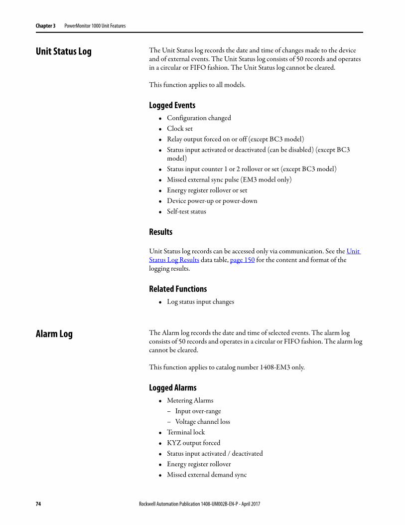
Chapter 3 PowerMonitor 1000 Unit Features
Unit Status Log The Unit Status log records the date and time of changes made to the device and of external events. The Unit Status log consists of 50 records and operates in a circular or FIFO fashion. The Unit Status log cannot be cleared.
This function applies to all models.
Logged Events• Configuration changed• Clock set• Relay output forced on or off (except BC3 model)• Status input activated or deactivated (can be disabled) (except BC3
model)• Status input counter 1 or 2 rollover or set (except BC3 model)• Missed external sync pulse (EM3 model only)• Energy register rollover or set• Device power-up or power-down• Self-test status
Results
Unit Status log records can be accessed only via communication. See the Unit Status Log Results data table, page 150 for the content and format of the logging results.
Related Functions• Log status input changes
Alarm Log The Alarm log records the date and time of selected events. The alarm log consists of 50 records and operates in a circular or FIFO fashion. The alarm log cannot be cleared.
This function applies to catalog number 1408-EM3 only.
Logged Alarms• Metering Alarms
– Input over-range– Voltage channel loss
• Terminal lock• KYZ output forced• Status input activated / deactivated• Energy register rollover• Missed external demand sync
74 Rockwell Automation Publication 1408-UM002B-EN-P - April 2017

PowerMonitor 1000 Unit Features Chapter 3
Results
Alarm log records can be accessed only via communication.
Related Functions• Unit Status Log
I/O Functions The I/O functions include Relay KYZ Output, Status Inputs, Configuration Lock Input, and Restore Defaults (BC3 model).
Relay KYZ Output
The KYZ output is a solid-state relay designed for low-power, long-life signaling operation. Its typical use is to provide a pulse output proportional to energy consumption to an external totalizer.
This function applies to catalog numbers 1408-TS3 and 1408-EM3 for energy pulse.
Operation
The KYZ output can operate in any of the following modes:• Energy pulse operation with fixed pulse width or toggle• Forced operation
Rockwell Automation Publication 1408-UM002B-EN-P - April 2017 75

Chapter 3 PowerMonitor 1000 Unit Features
Setup
KYZ-output set-up parameters are found in the Advanced Setup menu and are summarized in the table.
Commands• Force KYZ Output On• Force KYZ Output Off• Remove Force from KYZ
Related Functions• Configuration lock
Status Inputs The power monitor has two self-powered (24V DC) status inputs. Two typical uses for status inputs are to totalize external pulse meters and to synchronize the demand end of interval (EOI).
This function applies to catalog numbers 1408-TS3 and 1408-EM3.
Operation
Each time status input 1 sees an off-to-on transition, the status input 1 scale factor is added to the status input 1 count. The count continues to increase, rolling over to zero at a value of 9,999,999,999,999 (1012 – 1). Status input 2 operates in the same fashion. Status input 2 counter operates whether or not the input is used for demand EOI synchronization.
Table 18 - KYZ-output Set-up Parameters
Parameter Description Range Default User Setting
KYZ Output Parameter
0 = Disable1 = Wh Fwd2 = Wh Rev3 = VARh Fwd 4 = VARh Rev 5 = VAh
0…5 0
KYZ Output Scale The increase in value of the selected parameter that caused the output to change state
1…100,000
1000
KYZ Pulse Duration Setting
0 = toggle output50…1000 = duration of output pulse, rounded to 10 ms
0 or 50… 1000
250 ms
76 Rockwell Automation Publication 1408-UM002B-EN-P - April 2017

PowerMonitor 1000 Unit Features Chapter 3
Setup
The set-up parameters for pulse totalizing and scaling are in the Advanced Setup menu and are summarized in this table.
Setup for demand EOI synchronization is described in the Demand Metering section.
Metering Parameters• Status 1 Count x1,000,000 and x1• Status 2 Count x1,000,000 and x1
Commands
The following commands can be used to preset or reset the status input counters:
• Set Status 1 Count• Set Status 2 Count
Related Functions• Log status input changes• Configuration lock
Table 19 - Pulse Totalizing and Scaling Setup
Parameter Description Range Default User Setting Model
TR1 TR2 EM1 EM2 EM3
Status Input 1 Input Scale
When a status input sees an off to on transition, the status input count is increased by the scale factor.
1… 1,000,000 1 • • •
Status Input 2 Input Scale
1…1,000,000
1 • • •
Rockwell Automation Publication 1408-UM002B-EN-P - April 2017 77

Chapter 3 PowerMonitor 1000 Unit Features
Restore Defaults A user with administrative access to the power monitor (security policy login or Table Password) can issue a command to restore factory defaults.
If administrative access is not available due to a lost password, there is no backdoor method to log in as an admin or policy holder. There are two methods to restore factory defaults without administrative access. When factory defaults are restored, all user-configured values from the setup menus (for example, all security settings including Policy Holder information and accounts, metering configurations, network addressing) are cleared to their factory default settings.
1408-BC3 Model
Follow these steps to restore factory defaults.
1. Remove control power from the unit.
2. Working safely, remove the configuration lock jumper if present.
3. Working safely, install a jumper between the FD1 and FD2 terminals.
4. Apply control power for at least 30 seconds.
5. Remove control power.
6. Safely remove the jumper from FD1 and FD2.
7. Apply control power.
8. Starting with the first run web page on Ethernet or terminal emulation on RS-485, restore the unit configuration.
9. When setup is complete, safely reinstall the configuration lock jumper if previously installed.
IMPORTANT If present, the configuration lock jumper must be removed in order for a restore defaults command to succeed.
78 Rockwell Automation Publication 1408-UM002B-EN-P - April 2017
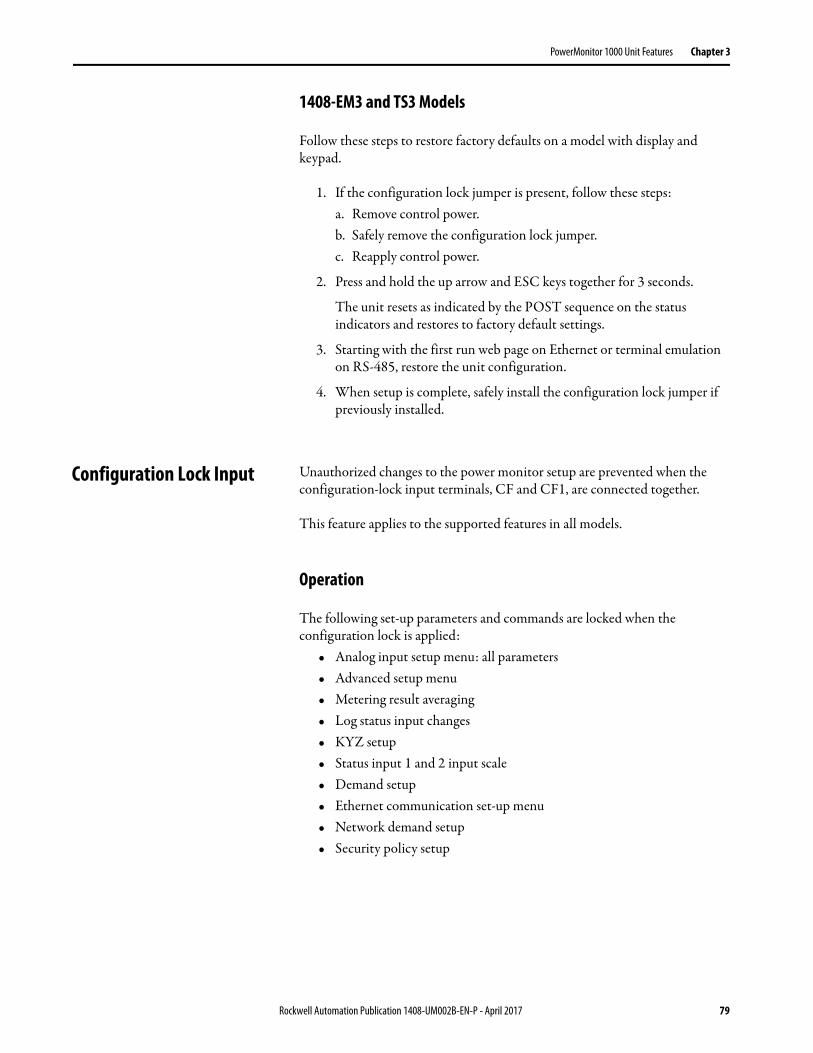
PowerMonitor 1000 Unit Features Chapter 3
1408-EM3 and TS3 Models
Follow these steps to restore factory defaults on a model with display and keypad.
1. If the configuration lock jumper is present, follow these steps:a. Remove control power.b. Safely remove the configuration lock jumper.c. Reapply control power.
2. Press and hold the up arrow and ESC keys together for 3 seconds.
The unit resets as indicated by the POST sequence on the status indicators and restores to factory default settings.
3. Starting with the first run web page on Ethernet or terminal emulation on RS-485, restore the unit configuration.
4. When setup is complete, safely install the configuration lock jumper if previously installed.
Configuration Lock Input Unauthorized changes to the power monitor setup are prevented when the configuration-lock input terminals, CF and CF1, are connected together.
This feature applies to the supported features in all models.
Operation
The following set-up parameters and commands are locked when the configuration lock is applied:
• Analog input setup menu: all parameters• Advanced setup menu• Metering result averaging• Log status input changes• KYZ setup• Status input 1 and 2 input scale• Demand setup• Ethernet communication set-up menu• Network demand setup• Security policy setup
Rockwell Automation Publication 1408-UM002B-EN-P - April 2017 79

Chapter 3 PowerMonitor 1000 Unit Features
The following commands are prohibited when the configuration lock is applied:
• Set kWh, kVARh, kVAh register• Clear all energy registers• Set status 1 or 2 count• Clear energy log• Force KYZ output on, off, or clear force• Restore factory defaults• Reset power monitor system
Setup
No setup is needed.
Miscellaneous Functions The power monitor includes a small number of miscellaneous functions that you can select. Set-up parameters of these functions are in the Advanced Configuration set-up menu.
Table 20 - Miscellaneous Function Setup
Parameter Description Range Default User Setting
New Table Password
Select a new password if desired to help prevent unauthorized changes to the unit setup.
0…9999 0
Metering Result Averaging
If enabled, metering results are averaged by using the previous eight cycles to smooth the results.
0 = Off1 = On
1
Log Status Input Changes(1)
(1) Log status input changes parameter is not accessible from the LCD screen.
If disabled, prevents routine status input changes from filling up the status log. Useful when a status input is used for pulse counting or demand EOI synch.
0 = Disable1 = Enable
0
Unit Error Action Determines the unit’s response to a hardware or firmware error.0 = Halt, make status indicator solid red1 = Reset the unit
0…1 1
Software Error Log Full Action
Determines the unit response when a firmware failure is detected and the error log is full.0 = Halt on error and wait for clear log command, make status indicator solid red1 = Perform a firmware reset
0…1 1
80 Rockwell Automation Publication 1408-UM002B-EN-P - April 2017

PowerMonitor 1000 Unit Features Chapter 3
Commands The power monitor offers the following commands. The power monitor Commands table can be accessed by using the LCD screen, the HyperTerminal communication tool, the Web interface, or via communication.
Commands that do not apply to the power monitor model are ignored.
Related Functions• Configuration lock
Table 21 - Commands
Command Parameters Action
Set kWh register GWh / kWh forward GWh / kWh reverse
Presets forward and reverse energy values, resets if parameters = 0
Set kVARh register GVARh / kVARh forward GVARh / kVARh reverse
Set kVAh register GVAh / kVAh forward GVAh / kVAh reverse
Clear all energy registers - Resets all energy values
Set Status 1 count New status 1 count Presets or resets status input count
Set Status 2 count New status 2 count
Clear energy log - Clears all data from energy log
Force KYZ output on - Forces the KYZ output state, over-rides automatic action
Force KYZ output off -
Remove force from KYZ - Restores automatic action of KYZ output as configured
Restore factory defaults - Clears all user-configured values from the setup menus to their factory default settings
Reset system - Warm reboot: Performs a power-on self test of the power monitor
Perform wiring diagnostics - Test the wiring connections
Clear min/max records Min/max record number Clears selected min/max record or all records if parameter = 0
Store and clear current load factor record
- Simulates end-of-month push of in-process current month into the monthly load factor record stack
Clear load factor log Clears all load factor log records
Store and clear current TOU record Simulates end-of-month push of in-process current month into the monthly TOU record stack
Clear TOU log Clears all TOU log records
Clear error log Clears the error log
Rockwell Automation Publication 1408-UM002B-EN-P - April 2017 81

Chapter 3 PowerMonitor 1000 Unit Features
Notes:
82 Rockwell Automation Publication 1408-UM002B-EN-P - April 2017

Chapter 4
Communication
PowerMonitor 1000 Memory Organization
The power monitor memory is organized similarly to that of a PLC-5® or SLC™ 500 programmable controller. Data tables organize individual data items of similar function. For example, the analog input set-up parameters are grouped in one data table, and voltage, current, and frequency metering results in another.
Appendix A provides a detailed list of the power monitor data tables.
Data Table Addressing
Data tables can be addressed in several ways.
CSP Addressing
This is also known as PLC-5 style or PCCC addressing. Addresses are written in the form Axx:yy where A is a letter describing the function of the data table, xx is the table number, and yy is the element within, or offset into, the table. For example, F23:0 is the CSP address of the first element in the energy metering results table.
CIP Addressing
This is also known as DeviceNet addressing. Addresses are of the form Object:Instance:Attribute. CIP addressing allows addressing of an entire data table. In CIP addressing, the energy metering results table object 4 (Assembly object), instance 16 (energy results table) and attribute 3 (data).
Modbus RTU Addressing
The data tables can be addressed by a Modbus RTU master using Modbus register addressing. The Modbus protocol supports four types of data: Discrete Input, Coil, Input Register, and Holding Register. The power monitor supports Input Registers (read-only) with addresses in the 30000 range and Holding Registers (read-write or write only) with addresses in the 40000 range. Using the same example as above, the energy results table has a Modbus address range of 30401…30438
Rockwell Automation Publication 1408-UM002B-EN-P - April 2017 83

Chapter 4 Communication
Data Table Access
Controllers and client applications can read or write single element, multiple elements or complete tables as permitted by the addressing selected.
Each data table’s read/write access is listed in Appendix A.
See Security on page 51 for information on how the power monitor is protected against inadvertent or unauthorized writes to data tables.
Data Table Data Format
The power monitor stores data in two basic formats.• Integer, in which the 16-bit word can be represented by a signed integer
value or a bit field• Floating-point, in the 32-bit IEEE 754 format
Modbus input registers and holding registers are 16 bits long. Floating point values in the data tables are represented as big-Endian two-register arrays in IEEE-754 floating point format. The Modbus client application must be able to reassemble the two-word array into a valid floating-point value.
An example Modbus address for a floating-point value is 40101-2. Register 40101 holds the most significant bytes of the number and 40102 holds the lowest significant bytes.
Communication Command Summary
This section lists the commands supported by each communication network type.
Serial DF1 Full-duplex, DF1 Half-duplex Slave, DH485 • PCCC Protected Logical Read w/ 2 Address Fields (CMD = 0x0F,
FUNC = 0xA1)• PCCC Protected Logical Write w/ 2 Address Fields (CMD = 0x0F,
FUNC = 0xA9)• PCCC Protected Logical Read w/ 3 Address Fields (CMD = 0x0F,
FUNC = 0xA2)• PCCC Protected Logical Write w/ 3 Address Fields (CMD = 0x0F,
FUNC = 0xAA)• PCCC Protected Logical Write w/ 4 Address Fields (CMD = 0x0F,
FUNC = 0xAB)• PCCC Status Diagnostics (CMD = 0x06, FUNC = 0x03)
84 Rockwell Automation Publication 1408-UM002B-EN-P - April 2017

Communication Chapter 4
Optional EtherNet/IP• CIP Generic Assembly Object (Class 04), Get & Set Attribute Single
for Attribute 3 (data)• CIP Generic Assembly Object (Class 04), Get Attribute Single for
Attribute 4 (size)• PCCC PLC5 Word Range Write Function
(CMD = 0x0F, FUNC = 0x00)• PCCC PLC5 Word Range Read Function
(CMD = 0x0F, FUNC = 0x01)• PCCC PLC5 Typed Write Function (CMD = 0x0F, FUNC = 0x67)• PCCC PLC5 Typed Read Function (CMD = 0x0F, FUNC = 0x68)• PCCC Protected Logical Read Function w/2 Address Fields
(CMD = 0x0F, FUNC = 0xA1)• PCCC Protected Logical Write Function w/2 Address Fields
(CMD = 0x0F, FUNC = 0xA9)• PCCC Protected Logical Read Function w/3 Address Fields
(CMD = 0x0F, FUNC = 0xA2)• PCCC Protected Logical Write Function w/3 Address Fields
(CMD = 0x0F, FUNC = 0xAA)• PCCC Status Diagnostics (CMD = 0x06, FUNC = 0x03)
Modbus RTU Serial and Optional Modbus/TCP Ethernet
The power monitor does not initiate Modbus commands but responds to commands sent by the Modbus master. These Modbus function codes are supported:
• 03 Read Holding Registers• 04 Read Input Registers• 16 Write Multiple Holding Registers• 08 Diagnostics
– 00 Echo Command Data– 02 Return Diagnostic Counters– 10 Clear Diagnostic Counters
• 06 Write Single Holding Register
Rockwell Automation Publication 1408-UM002B-EN-P - April 2017 85
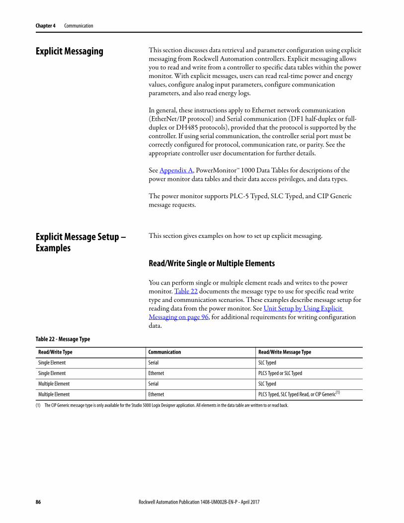
Chapter 4 Communication
Explicit Messaging This section discusses data retrieval and parameter configuration using explicit messaging from Rockwell Automation controllers. Explicit messaging allows you to read and write from a controller to specific data tables within the power monitor. With explicit messages, users can read real-time power and energy values, configure analog input parameters, configure communication parameters, and also read energy logs.
In general, these instructions apply to Ethernet network communication (EtherNet/IP protocol) and Serial communication (DF1 half-duplex or full-duplex or DH485 protocols), provided that the protocol is supported by the controller. If using serial communication, the controller serial port must be correctly configured for protocol, communication rate, or parity. See the appropriate controller user documentation for further details.
See Appendix A, PowerMonitor™ 1000 Data Tables for descriptions of the power monitor data tables and their data access privileges, and data types.
The power monitor supports PLC-5 Typed, SLC Typed, and CIP Generic message requests.
Explicit Message Setup – Examples
This section gives examples on how to set up explicit messaging.
Read/Write Single or Multiple Elements
You can perform single or multiple element reads and writes to the power monitor. Table 22 documents the message type to use for specific read write type and communication scenarios. These examples describe message setup for reading data from the power monitor. See Unit Setup by Using Explicit Messaging on page 96, for additional requirements for writing configuration data.
Table 22 - Message Type
Read/Write Type Communication Read/Write Message Type
Single Element Serial SLC Typed
Single Element Ethernet PLC5 Typed or SLC Typed
Multiple Element Serial SLC Typed
Multiple Element Ethernet PLC5 Typed, SLC Typed Read, or CIP Generic(1)
(1) The CIP Generic message type is only available for the Studio 5000 Logix Designer application. All elements in the data table are written to or read back.
86 Rockwell Automation Publication 1408-UM002B-EN-P - April 2017
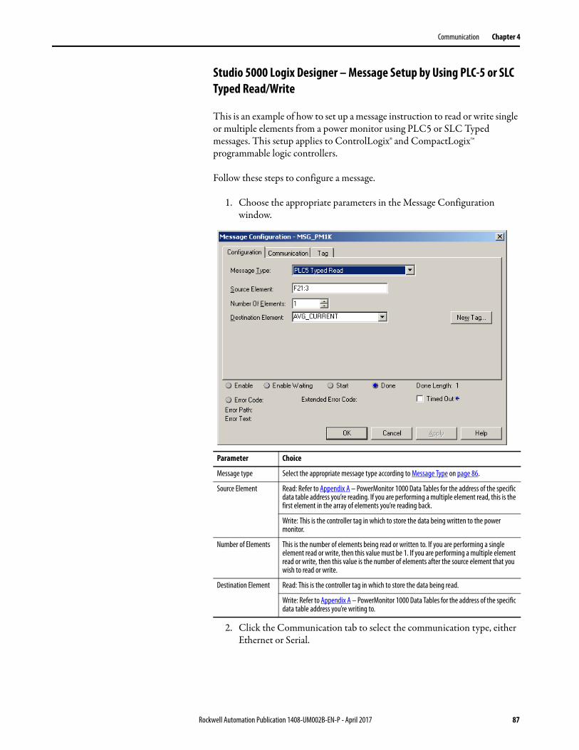
Communication Chapter 4
Studio 5000 Logix Designer – Message Setup by Using PLC-5 or SLC Typed Read/Write
This is an example of how to set up a message instruction to read or write single or multiple elements from a power monitor using PLC5 or SLC Typed messages. This setup applies to ControlLogix® and CompactLogix™ programmable logic controllers.
Follow these steps to configure a message.
1. Choose the appropriate parameters in the Message Configuration window.
2. Click the Communication tab to select the communication type, either Ethernet or Serial.
Parameter Choice
Message type Select the appropriate message type according to Message Type on page 86.
Source Element Read: Refer to Appendix A – PowerMonitor 1000 Data Tables for the address of the specific data table address you’re reading. If you are performing a multiple element read, this is the first element in the array of elements you’re reading back.
Write: This is the controller tag in which to store the data being written to the power monitor.
Number of Elements This is the number of elements being read or written to. If you are performing a single element read or write, then this value must be 1. If you are performing a multiple element read or write, then this value is the number of elements after the source element that you wish to read or write.
Destination Element Read: This is the controller tag in which to store the data being read.
Write: Refer to Appendix A – PowerMonitor 1000 Data Tables for the address of the specific data table address you’re writing to.
Rockwell Automation Publication 1408-UM002B-EN-P - April 2017 87
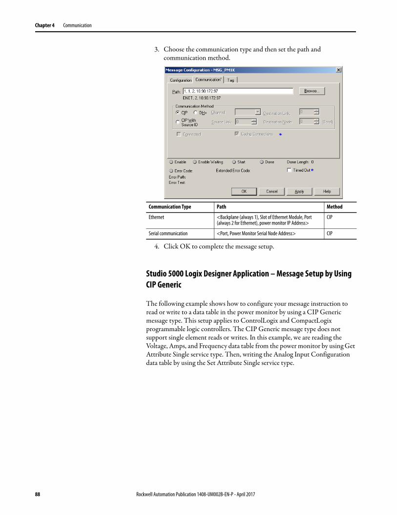
Chapter 4 Communication
3. Choose the communication type and then set the path and communication method.
4. Click OK to complete the message setup.
Studio 5000 Logix Designer Application – Message Setup by Using CIP Generic
The following example shows how to configure your message instruction to read or write to a data table in the power monitor by using a CIP Generic message type. This setup applies to ControlLogix and CompactLogix programmable logic controllers. The CIP Generic message type does not support single element reads or writes. In this example, we are reading the Voltage, Amps, and Frequency data table from the power monitor by using Get Attribute Single service type. Then, writing the Analog Input Configuration data table by using the Set Attribute Single service type.
Communication Type Path Method
Ethernet <Backplane (always 1), Slot of Ethernet Module, Port (always 2 for Ethernet), power monitor IP Address>
CIP
Serial communication <Port, Power Monitor Serial Node Address> CIP
88 Rockwell Automation Publication 1408-UM002B-EN-P - April 2017
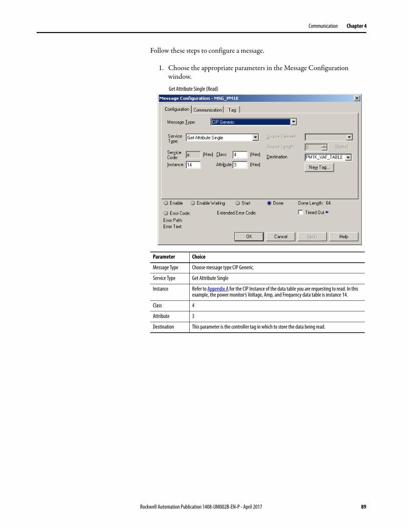
Communication Chapter 4
Follow these steps to configure a message.
1. Choose the appropriate parameters in the Message Configuration window.
Parameter Choice
Message Type Choose message type CIP Generic.
Service Type Get Attribute Single
Instance Refer to Appendix A for the CIP Instance of the data table you are requesting to read. In this example, the power monitor’s Voltage, Amp, and Frequency data table is instance 14.
Class 4
Attribute 3
Destination This parameter is the controller tag in which to store the data being read.
Get Attribute Single (Read)
Rockwell Automation Publication 1408-UM002B-EN-P - April 2017 89
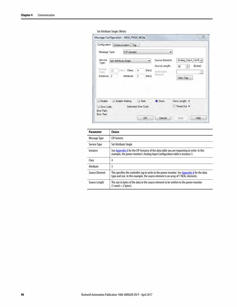
Chapter 4 Communication
Parameter Choice
Message Type CIP Generic
Service Type Set Attribute Single
Instance See Appendix A for the CIP Instance of the data table you are requesting to write. In this example, the power monitor's Analog Input Configuration table is instance 3.
Class 4
Attribute 3
Source Element This specifies the controller tag to write to the power monitor. See Appendix A for the data type and size. In this example, the source element is an array of 7 REAL elements.
Source Length The size in bytes of the data in the source element to be written to the power monitor (1 word = 2 bytes).
Set Attribute Single (Write)
90 Rockwell Automation Publication 1408-UM002B-EN-P - April 2017
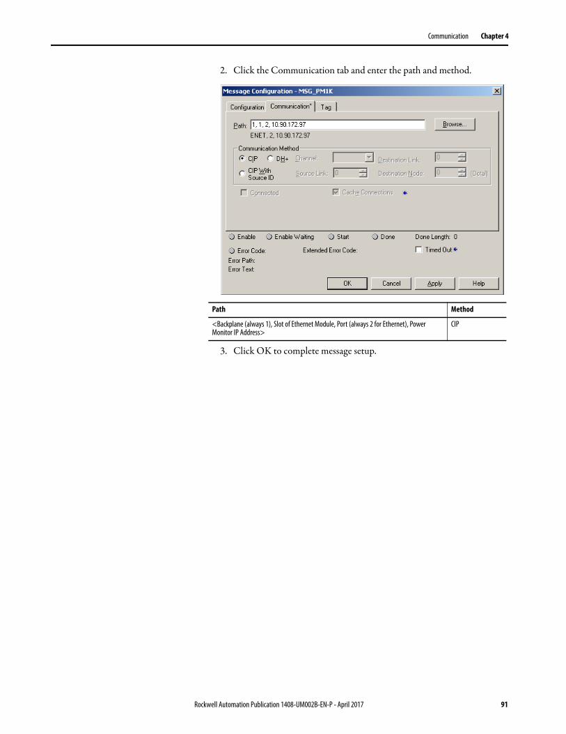
Communication Chapter 4
2. Click the Communication tab and enter the path and method.
3. Click OK to complete message setup.
Path Method
<Backplane (always 1), Slot of Ethernet Module, Port (always 2 for Ethernet), Power Monitor IP Address>
CIP
Rockwell Automation Publication 1408-UM002B-EN-P - April 2017 91

Chapter 4 Communication
RSLogix500 Software - Message Setup by Using PLC-5 or SLC Typed Read/Write
The following is an example of how to set up your message instruction to read or write single or multiple elements to a power monitor using Peer-To-Peer PLC-5 or CPU 500 Typed messages in RSLogix™500 software. This setup applies to SLC and MicroLogix programmable logic controllers.
Follow these steps to configure a message.
1. Set your MSG instruction.
2. Click Setup Screen at the bottom of the message instruction.
The message configuration window for either Ethernet network or Serial communication appears.
Parameter Choice
Read/Write Select Read or Write
Target Device Select the appropriate message type according to Message Type on page 86.
Local/Remote Select Local
Control Block Select an available Integer word. In this example, we used N7:0.
92 Rockwell Automation Publication 1408-UM002B-EN-P - April 2017

Communication Chapter 4
3. Choose the appropriate parameters in the Message Configuration window.
Message setup is complete for Serial communication.
Ethernet Network Communication
Communication Type Parameter Choice
Ethernet Data Table Address (This Controller) Read: This is the controller tag in which to store the data being read
Write: This is the controller tag that stores the value to be written to the power monitor.
Size in Elements This is the number of elements being read or written to. If you are performing a single element read or write, then this value is 1. If you are performing a multiple element read or write, then this value is the number of elements after the source element that you wish to read or write.
Channel 1
Data Table Address (Target Device)
Refer to Appendix A for the address of the specific data value you’re reading or writing to.
MultiHop Yes
Serial Communication
Communication Type Parameter Choice
Serial Data Table Address (This Controller) Read: This is the controller tag in which to store the data being read
Write: This is the controller tag that stores the value to be written to the power monitor.
Size in Elements This is the number of elements being read or written to. If you are performing a single element read or write, then this value is 1. If you are performing a multiple element read or write, then this value is the number of elements after the source element that you wish to read or write.
Channel 0
Data Table Address (Target Device) Refer to Appendix A for the address of the specific data value you’re reading or writing to.
Local Node This is the serial node address of your power monitor.
Rockwell Automation Publication 1408-UM002B-EN-P - April 2017 93

Chapter 4 Communication
4. Click the MultiHop tab if configuring Ethernet communication.
5. Enter the IP Address of the power monitor in the To Address box.
Message setup is complete.
RSLogix5 Software - Message Setup Using PLC-5 or SLC Typed Read/Write
The following is an example of how to set up your message instruction to read or write single or multiple elements to a power monitor using PLC-5 or SLC Typed messages in RSLogix5. This setup applies to PLC-5 programmable logic controllers.
Follow these steps to configure a message.
1. Choose an available message data block in your message instruction.
In this example, we used MG9:0.
2. Click Setup Screen at the bottom of the message instruction.
The message configuration window for either Ethernet network or Serial communcation appears.
94 Rockwell Automation Publication 1408-UM002B-EN-P - April 2017

Communication Chapter 4
3. Choose the appropriate parameters in the Message Configuration window.
Ethernet Network Communication
Communication Type Parameter Choice
Ethernet Communication Command Select the appropriate message type according to Message Type on page 86.
Data Table Address (This Controller) Read: This is the controller tag in which to store the data being read.
Write: This is the controller tag that stores the value to be written to the power monitor.
Size in Elements This is the number of elements being read or written to. If you are performing a single element read or write, then this value is 1. If you are performing a multiple element read or write, then this value is the number of elements after the source element that you wish to read or write.
Port Number 2
Data Table Address (Target Device) Refer to Appendix A for the address of the specific data value you’re reading or writing to.
MultiHop Yes
Serial Communication
Communication Type Parameter Choice
Serial Communication Command Select the appropriate message type according to Message Type on page 86.
Data Table Address Read: This is the controller tag in which to store the data being read.
Write: This is the controller tag that stores the value to be written to the power monitor.
Size in Elements This is the number of elements being read or written to. If you are performing a single element read or write, then this value is 1. If you are performing a multiple element read or write, then this value is the number of elements after the source element that you wish to read or write.
Port Number 0
Data Table Address (Target Device) Refer to Appendix A for the address of the specific data value you’re reading or writing to.
Local Station Address This is the serial node address of your power monitor.
Local / Remote Local
Rockwell Automation Publication 1408-UM002B-EN-P - April 2017 95
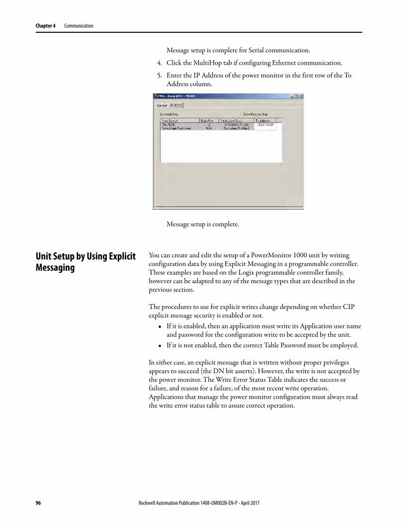
Chapter 4 Communication
Message setup is complete for Serial communication.
4. Click the MultiHop tab if configuring Ethernet communication.
5. Enter the IP Address of the power monitor in the first row of the To Address column.
Message setup is complete.
Unit Setup by Using Explicit Messaging
You can create and edit the setup of a PowerMonitor 1000 unit by writing configuration data by using Explicit Messaging in a programmable controller. These examples are based on the Logix programmable controller family, however can be adapted to any of the message types that are described in the previous section.
The procedures to use for explicit writes change depending on whether CIP explicit message security is enabled or not.
• If it is enabled, then an application must write its Application user name and password for the configuration write to be accepted by the unit.
• If it is not enabled, then the correct Table Password must be employed.
In either case, an explicit message that is written without proper privileges appears to succeed (the DN bit asserts). However, the write is not accepted by the power monitor. The Write Error Status Table indicates the success or failure, and reason for a failure, of the most recent write operation. Applications that manage the power monitor configuration must always read the write error status table to assure correct operation.
96 Rockwell Automation Publication 1408-UM002B-EN-P - April 2017
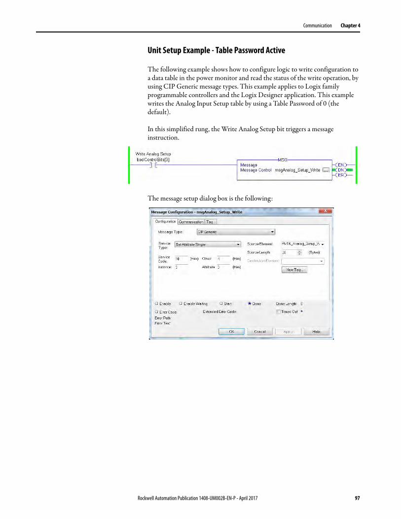
Communication Chapter 4
Unit Setup Example - Table Password Active
The following example shows how to configure logic to write configuration to a data table in the power monitor and read the status of the write operation, by using CIP Generic message types. This example applies to Logix family programmable controllers and the Logix Designer application. This example writes the Analog Input Setup table by using a Table Password of 0 (the default).
In this simplified rung, the Write Analog Setup bit triggers a message instruction.
The message setup dialog box is the following:
Rockwell Automation Publication 1408-UM002B-EN-P - April 2017 97

Chapter 4 Communication
The Communication tab is the following:
The source data tag is a REAL array of 7 elements:
The write sets up the power monitor for a Wye system, with a 4160:120 PT ratio, 1000:5 CT ratio, and a low range on system power factor. Note that Element 0 (Table Password) value is 0.
The following rung reads the Write Error Status table:
98 Rockwell Automation Publication 1408-UM002B-EN-P - April 2017
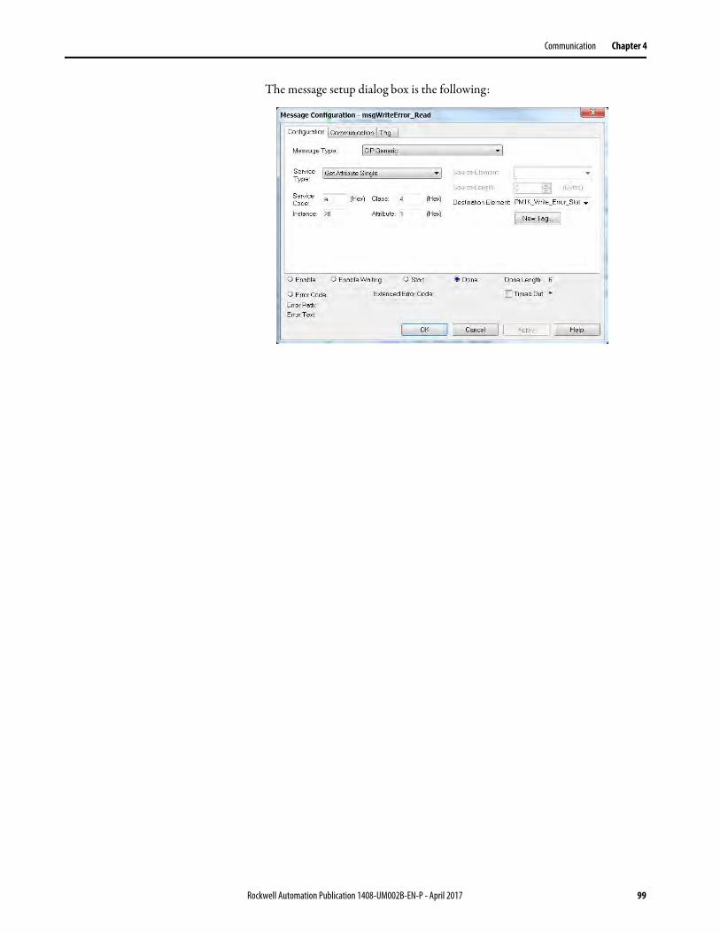
Communication Chapter 4
The message setup dialog box is the following:
Rockwell Automation Publication 1408-UM002B-EN-P - April 2017 99

Chapter 4 Communication
This status rung displays the content of the Write Error Status table. The value of element 0 is the instance number last written, and the element 1 value of -1 indicates success. The table also indicates other security information, for instance, web security is enabled and an admin user is logged in. If the table password is not valid, element 0 still indicates instance 3, but element 1 indicates 0 as the offending element (the table password).
Unit Setup Example - CIP Explicit Message Security Enabled
The following example shows how to use CIP Generic message types to do the following:
• Set up logic to log in as an Application user• Write configuration to a data table in the power monitor• Read the status of the write operation• Log off
This example applies to Logix family programmable controllers and the Logix Designer application. Like the previous example, this example writes the Analog Input Setup table. In this example, CIP Explicit Message Security is enabled and an Application type user is created with a User Name of ‘app’ and a Password of ‘app’.
This rung writes the User Name when triggered by the input bit:
100 Rockwell Automation Publication 1408-UM002B-EN-P - April 2017

Communication Chapter 4
The message setup dialog box is the following.
The User Name data table is the following.
The user name is padded with NULL characters so the string length is 32 characters.
Within 30 seconds, this rung writes the Password to the power monitor.
Its message setup dialog box is similar except it writes to Instance 33 from the Password tags, another 32-character STRING tag.
IMPORTANT The MSG instructions to write the user name and password fails if the strings are not 32 characters in length.
Rockwell Automation Publication 1408-UM002B-EN-P - April 2017 101

Chapter 4 Communication
The rungs to write the analog input setup and read the write error status are identical to those in the previous example. The source data tag is also the same, except its element 0 has a value of -1 (it can be any value, since with CIP Explicit Message Security enabled it is ignored). The write error status display rung indicates success and also that application security is active and an application account is active.
After the setup data is written and confirmed, this rung logs the application off of the application account by writing a value of 8 to Instance 9, element 2 and zeroes to the remaining elements of Instance 9.
A read of the Write Error Status table indicates success for the write to Instance 9 and that the application account is now inactive.
102 Rockwell Automation Publication 1408-UM002B-EN-P - April 2017

Communication Chapter 4
Writing Security Credentials - Modbus/TCP
Application security, when enabled, is active on communication between Modbus/TCP clients and the power monitor. The specifics of establishing communication are dependent upon the client used.
The client does not always natively handle STRING data. If the client does not handle STRING data, create Modbus arrays of 16 words that represent the ASCII value of the user name, password, and NULL padding. For example, a user name of ‘app1’ can be expressed as a 16 = word array 24944, 28721, 0, 0, 0, 0, 0, 0, 0, 0, 0, 0, 0, 0, 0, 0, where 24944 and 28721 are the decimal representations of the hexadecimal ASCII codes of ‘ap’ and ‘p1’ respectively.
Reading Logs You can perform explicit messages to read data from log records in the power monitor.
For information on setting up explicit messages to the power monitor, please refer to Explicit Message Setup – Examples on page 86.
The following logs can be read into a controller depending on the logs supported by your power monitor.
• Unit Status Log• Min/Max Log• Energy Log• Load Factor Log (EM3 model only)• Time of Use Log kWh• Time of Use Log kVAR• Time of Use Log kVA• Internal Error Log• Alarm Log (EM3 model only)
Please refer to Appendix A for the data table address of the specific log you are requesting.
Log Data Table Methodology
The log data tables only hold one record instance for a specific log. Successive reads of the data table return a successive record instance for that log. By writing to specific configuration elements in the Log Request Table data table, you can configure the log to return in a forward or reverse direction. You can also configure the log to return a specific record for all logs except the Unit Status Log, and Energy Log.
Refer to Log Request Table on page 140 for more information.
Rockwell Automation Publication 1408-UM002B-EN-P - April 2017 103
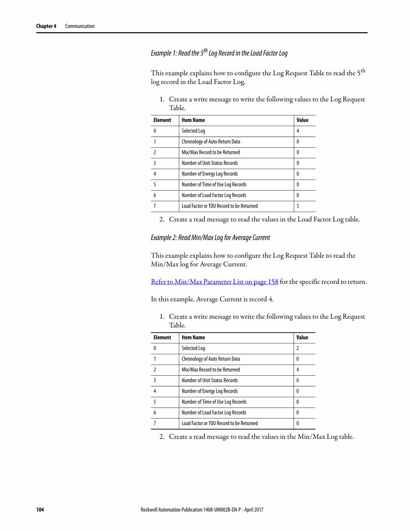
Chapter 4 Communication
Example 1: Read the 5th Log Record in the Load Factor Log
This example explains how to configure the Log Request Table to read the 5th log record in the Load Factor Log.
1. Create a write message to write the following values to the Log Request Table.
2. Create a read message to read the values in the Load Factor Log table.
Example 2: Read Min/Max Log for Average Current
This example explains how to configure the Log Request Table to read the Min/Max log for Average Current.
Refer to Min/Max Parameter List on page 158 for the specific record to return.
In this example, Average Current is record 4.
1. Create a write message to write the following values to the Log Request Table.
2. Create a read message to read the values in the Min/Max Log table.
Element Item Name Value
0 Selected Log 4
1 Chronology of Auto Return Data 0
2 Mix/Max Record to be Returned 0
3 Number of Unit Status Records 0
4 Number of Energy Log Records 0
5 Number of Time of Use Log Records 0
6 Number of Load Factor Log Records 0
7 Load Factor or TOU Record to be Returned 5
Element Item Name Value
0 Selected Log 2
1 Chronology of Auto Return Data 0
2 Mix/Max Record to be Returned 4
3 Number of Unit Status Records 0
4 Number of Energy Log Records 0
5 Number of Time of Use Log Records 0
6 Number of Load Factor Log Records 0
7 Load Factor or TOU Record to be Returned 0
104 Rockwell Automation Publication 1408-UM002B-EN-P - April 2017

Communication Chapter 4
Calculating Energy Log Depth
How long the Energy Log takes to fill can be as little as 288 hours or as long as three years depending on how you configure the log rate. The Energy records maximum depth is 17280 records that covers the following:
• Status 1 and 2 counters (except BC3)• Real, Reactive, and Apparent Demand (except BC3)• Real, Reactive, and Apparent Energy• Demand Power Factor (except BC3)
Implicit messaging:• I/O connection• User configured instance
Accessing Energy Logs by Using FTP
You can retrieve the energy logs by using File Transfer Protocol (FTP) and native Ethernet communication. A number of FTP clients are available, many at no cost. The following examples show how to access and download the energy log files using an FTP client.
Example of Using Microsoft Internet Explorer as the FTP Client
To use Microsoft Internet Explorer as the FTP client, follow these steps.
1. Open Internet Explorer and browse to the FTP server of the PowerMonitor 1000 unit.
The URL is ftp://<ip_address>/, where <ip_address> is the one assigned to the native Ethernet port.
2. Select the energy log files from the list and click Save As to save the files in the location of your choosing.
IMPORTANT There are two files available for the energy log. The file elgfwd.csv displays the energy log records starting with the oldest record. The elginv.csv file displays the energy log records starting with the most recent record.
IMPORTANT If the PowerMonitor 1000 Web Page Access Security is enabled, you can access the energy logs directly by using the following URL syntax:ftp://<user name>@<ip_address>/elgfwd.csvftp://<user name>@<ip_address>/elginv.csv
Rockwell Automation Publication 1408-UM002B-EN-P - April 2017 105

Chapter 4 Communication
Example of Using Microsoft Windows Command-line FTP Client
To use Microsoft Windows Command-line as the FTP client, follow these steps.
1. From the Windows Start menu, choose Run.
2. Type cmd and click OK.
3. At the prompt, type ftp and press Enter (this time and after each command).
4. Type 'open aaa.bbb.ccc.ddd' (the IP address of the power monitor).
You are prompted for a user name and password.
5. If the PowerMonitor 1000 Web Page Security Access is enabled, enter a valid account user name and password.
If the PowerMonitor 1000 Web Page Security Access is disabled, press Enter when prompted for the user name and password.
6. To view a directory of log files, type 'dir'.
7. To download a log file, type 'get' followed by a space and the file name.
The file is saved to the folder where the FTP client was started (typically the Windows desktop).
There are many other FTP commands you can use. We suggest searching the Web for 'command-line ftp client' for more information.
106 Rockwell Automation Publication 1408-UM002B-EN-P - April 2017
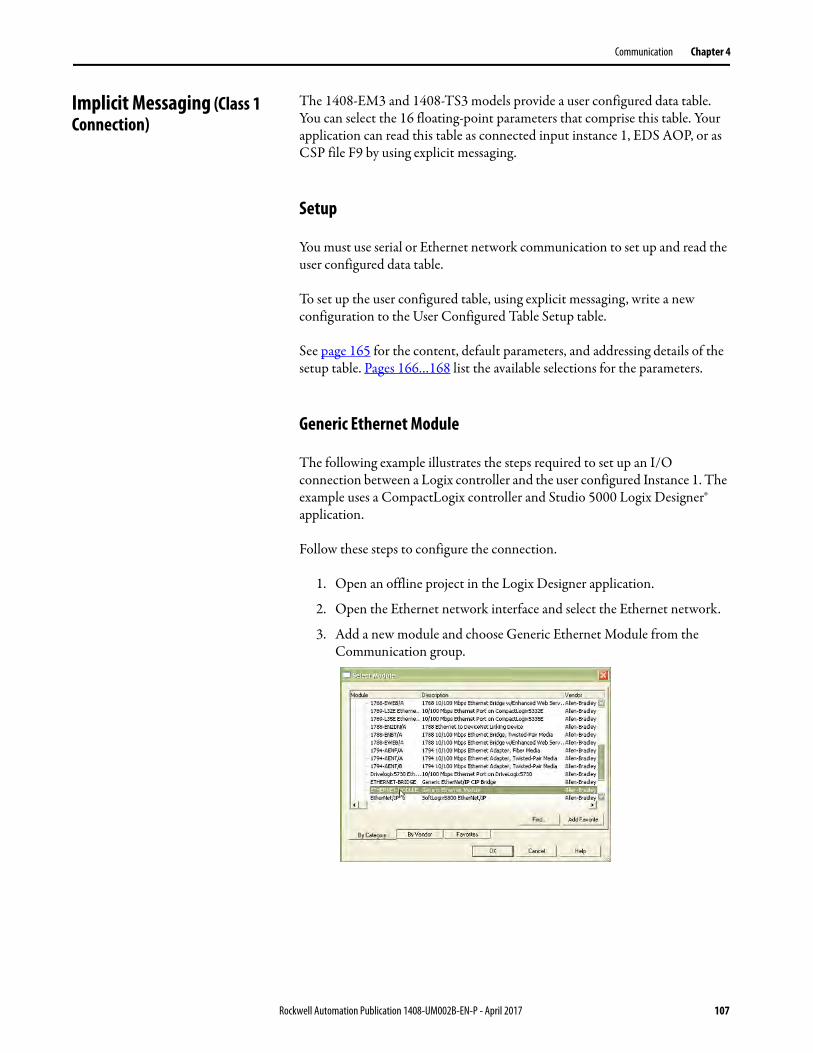
Communication Chapter 4
Implicit Messaging (Class 1 Connection)
The 1408-EM3 and 1408-TS3 models provide a user configured data table. You can select the 16 floating-point parameters that comprise this table. Your application can read this table as connected input instance 1, EDS AOP, or as CSP file F9 by using explicit messaging.
Setup
You must use serial or Ethernet network communication to set up and read the user configured data table.
To set up the user configured table, using explicit messaging, write a new configuration to the User Configured Table Setup table.
See page 165 for the content, default parameters, and addressing details of the setup table. Pages 166…168 list the available selections for the parameters.
Generic Ethernet Module
The following example illustrates the steps required to set up an I/O connection between a Logix controller and the user configured Instance 1. The example uses a CompactLogix controller and Studio 5000 Logix Designer® application.
Follow these steps to configure the connection.
1. Open an offline project in the Logix Designer application.
2. Open the Ethernet network interface and select the Ethernet network.
3. Add a new module and choose Generic Ethernet Module from the Communication group.
Rockwell Automation Publication 1408-UM002B-EN-P - April 2017 107

Chapter 4 Communication
4. Configure the properties of the new module and click OK.
5. On the connection tab, enter the desired Requested Packet Interval (RPI).
Do not enter an RPI less than 100 ms for the PowerMonitor 1000 unit.
Parameter Choice
Name Your choice of name
Comm Format Input Data - REAL
IP Address The IP address of your power monitor
Input Assembly Instance 1; Size 16 (32-bit)
Output Assembly Instance 2
Configuration Assembly Instance 3; Size 0
Open Module Properties Leave checked
108 Rockwell Automation Publication 1408-UM002B-EN-P - April 2017
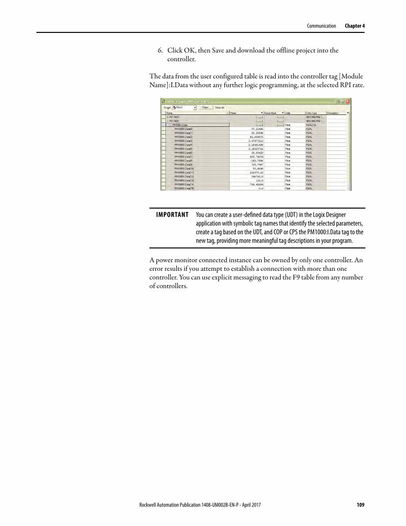
Communication Chapter 4
6. Click OK, then Save and download the offline project into the controller.
The data from the user configured table is read into the controller tag [Module Name]:I.Data without any further logic programming, at the selected RPI rate.
A power monitor connected instance can be owned by only one controller. An error results if you attempt to establish a connection with more than one controller. You can use explicit messaging to read the F9 table from any number of controllers.
IMPORTANT You can create a user-defined data type (UDT) in the Logix Designer application with symbolic tag names that identify the selected parameters, create a tag based on the UDT, and COP or CPS the PM1000:I.Data tag to the new tag, providing more meaningful tag descriptions in your program.
Rockwell Automation Publication 1408-UM002B-EN-P - April 2017 109

Chapter 4 Communication
EDS Add-on Profile (Native EtherNet/IP units only)
The PowerMonitor 1000 unit can be added to a Logix Designer application with an electronic data sheet (EDS) based AOP (add-on profile) in RSLogix 5000® software version 20 or Studio 5000 version 21 or later. You need to register the PowerMonitor 1000 EDS file on the computer on which software project development is done. You can upload the EDS file directly from the unit in RSLinx® software.
The PowerMonitor 1000 module is displayed under the catalog number 1408.
To use the EDS Add-on Profile, follow these steps.
1. Select the 1408 Powermonitor 1000 module and click Create.
2. Enter the name and IP address of the power monitor.
IMPORTANT The EDS AOP is available for PowerMonitor 1000 units with firmware revision 4.010 and later.
110 Rockwell Automation Publication 1408-UM002B-EN-P - April 2017
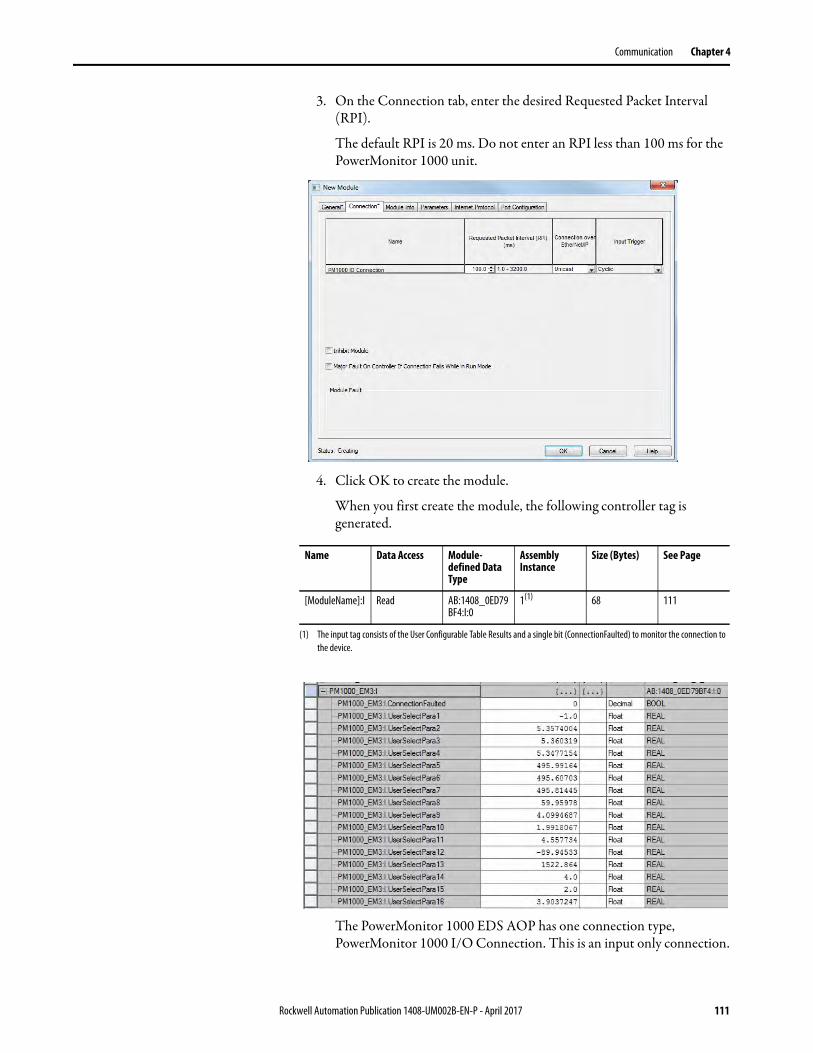
Communication Chapter 4
3. On the Connection tab, enter the desired Requested Packet Interval (RPI).
The default RPI is 20 ms. Do not enter an RPI less than 100 ms for the PowerMonitor 1000 unit.
4. Click OK to create the module.
When you first create the module, the following controller tag is generated.
The PowerMonitor 1000 EDS AOP has one connection type, PowerMonitor 1000 I/O Connection. This is an input only connection.
Name Data Access Module-defined Data Type
Assembly Instance
Size (Bytes) See Page
[ModuleName]:I Read AB:1408_0ED79BF4:I:0
1(1)
(1) The input tag consists of the User Configurable Table Results and a single bit (ConnectionFaulted) to monitor the connection to the device.
68 111
Rockwell Automation Publication 1408-UM002B-EN-P - April 2017 111
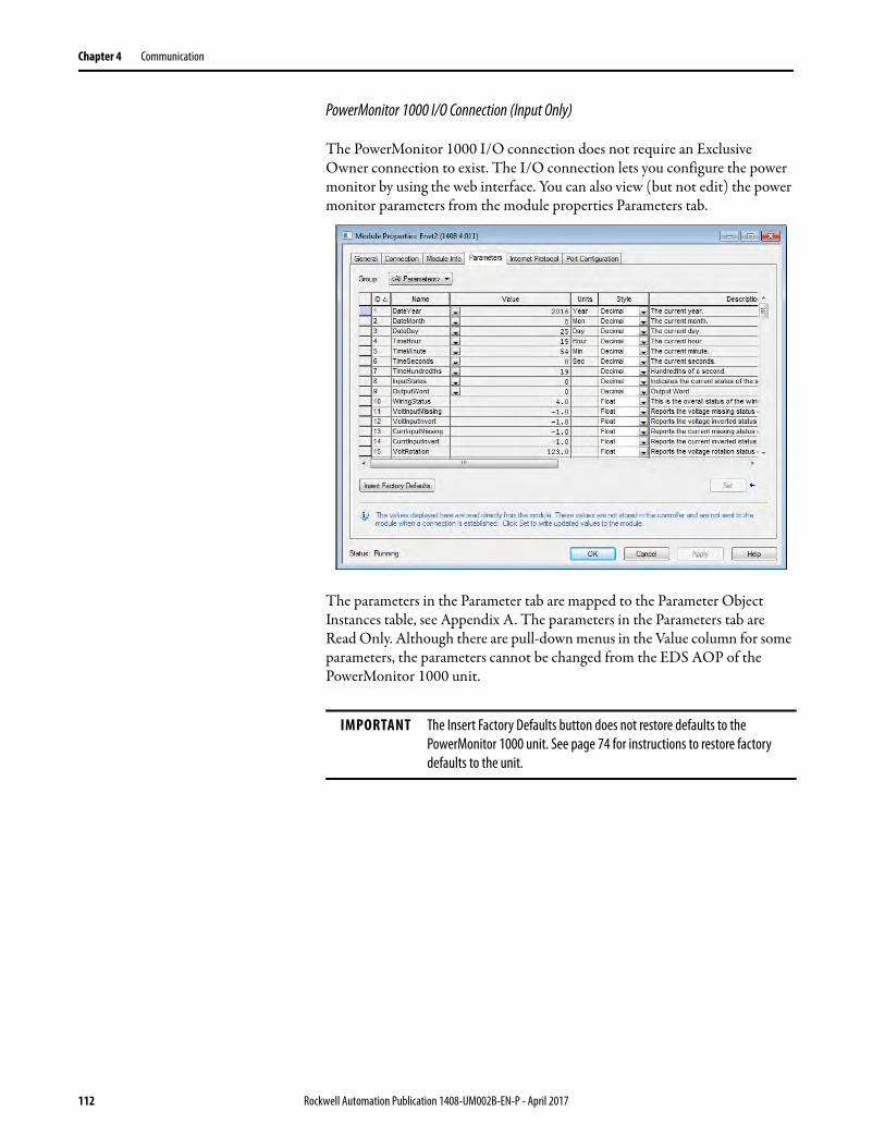
Chapter 4 Communication
PowerMonitor 1000 I/O Connection (Input Only)
The PowerMonitor 1000 I/O connection does not require an Exclusive Owner connection to exist. The I/O connection lets you configure the power monitor by using the web interface. You can also view (but not edit) the power monitor parameters from the module properties Parameters tab.
The parameters in the Parameter tab are mapped to the Parameter Object Instances table, see Appendix A. The parameters in the Parameters tab are Read Only. Although there are pull-down menus in the Value column for some parameters, the parameters cannot be changed from the EDS AOP of the PowerMonitor 1000 unit.
IMPORTANT The Insert Factory Defaults button does not restore defaults to the PowerMonitor 1000 unit. See page 74 for instructions to restore factory defaults to the unit.
112 Rockwell Automation Publication 1408-UM002B-EN-P - April 2017
Communication Chapter 4
SCADA Applications This section covers RSLinx driver setup, and OPC setup by using the RSLinx OPC Server.
RSLinx Classic Drivers Configuration
Install the PowerMonitor 1000 unit EDS file on the computer running RSLinx Classic software before configuring drivers. RSLinx software supports DF1 half-duplex, DF1 full-duplex, and EtherNet/IP network communication.
Configure DF1 Half-duplex
See RS-485 Multi-drop Typical Wiring on page 32 for information on the physical network connections. Verify the DF1 Address of the power monitor, and that its Protocol Setting is DF-1 Half Duplex Slave or Auto Sense.
1. Create a DF1 Polling Master Driver in RSLinx software.
2. Verify that the communication rate in the Port Configuration tab is the same as the communication rate set for your power monitor.
3. Set the Error Checking Mode in the DF1 Protocol Settings tab to CRC.
4. Set the Destination Station Out-of-List Strategy in the Polling Strategies tab to Allow Msgs to Stns that are not in lists.
5. Add the DF1 address of your power monitor to the Normal polling list in the Define Polling Lists tab.
6. Click OK when done.
7. Perform an RSWho to verify that RSLinx software is communicating to the power monitor.
RSLinx software driver configuration is complete.
Configure DF1 Full-duplex
See RS-485 Point-to-point Typical Wiring on page 32 for information on the physical network connections.
1. Create a RS232 DF1 devices driver in RSLinx Classic software.
2. Perform an Auto-configure.
3. Verify connections if Auto-configure fails.
4. Perform an RSWho to verify that RSLinx software is communicating to the power monitor.
RSLinx software driver configuration is complete.
Rockwell Automation Publication 1408-UM002B-EN-P - April 2017 113

Chapter 4 Communication
Configure RSLinx Software Driver Configuration for DH485
See RS-485 Multi-drop Typical Wiring on page 32 for information on the physical network connections.
1. Open the RSLinx Classic Launch Control Panel.
2. Start RSLinx software to run as normal application, not as service.
3. Create a 1747-PIC/AIC+ Driver in RSLinx software.
4. Verify that the communication rate is the same as the communication rate set for your power monitor.
5. Set the node address and maximum node address of RSLinx Driver.
6. Perform an RSWho to verify that RSLinx software is communicating to the power monitor.
7. Restart RSLinx software to run as service.
114 Rockwell Automation Publication 1408-UM002B-EN-P - April 2017
Communication Chapter 4
Configure EtherNet/IP Network by Using Ethernet Devices Driver
1. Create an Ethernet devices driver in RSLinx Classic software.
2. Add the IP address of the power monitor to the driver station mapping.
3. Perform an RSWho to verify that RSLinx software is communicating to the power monitor.
RSLinx software driver configuration is complete.
Configure EtherNet/IP Network by Using EtherNet/IP Driver
1. Create an EtherNet/IP driver in RSLinx Classic software.
2. Make selections to browse the local or remote subnet as appropriate.
3. Perform an RSWho to verify that RSLinx software is communicating to the power monitor.
RSLinx software driver configuration is complete.
RSLinx Classic Software OPC Server Setup
You can set up RSLinx Classic software as an OPC Server to serve data from a power monitor to an OPC 2.0 compliant application. You must first set up an RSLinx driver to communicate to the power monitor. You can then create an OPC topic to serve data to your SCADA application.
IMPORTANT The power monitor makes a connection to either the RSLinx Ethernet Devices driver or the EtherNet/IP driver on a single computer but not both simultaneously.
Rockwell Automation Publication 1408-UM002B-EN-P - April 2017 115
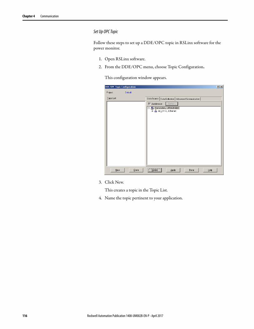
Chapter 4 Communication
Set Up OPC Topic
Follow these steps to set up a DDE/OPC topic in RSLinx software for the power monitor.
1. Open RSLinx software.
2. From the DDE/OPC menu, choose Topic Configuration.
This configuration window appears.
3. Click New.
This creates a topic in the Topic List.
4. Name the topic pertinent to your application.
116 Rockwell Automation Publication 1408-UM002B-EN-P - April 2017

Communication Chapter 4
5. In the right pane, under the Data Source tab, browse to your power monitor.
You can use a serial or Ethernet network driver.
6. Make sure that the topic is highlighted in the left pane, and that the power monitor is also highlighted in the right pane, then click Apply.
7. Click the Data Collection tab.
TIP When using a DH485 driver, change the connection type to local addressing mode in the Advanced Communication tab. Local addressing mode is especially important when several topics use the DH485 driver.
Rockwell Automation Publication 1408-UM002B-EN-P - April 2017 117

Chapter 4 Communication
8. From the Processor Type menu, choose SLC 503+.
9. Click Done.
OPC Topic configuration is complete.
You can now use the RSLinx OPC Server, and the topic just created, to serve data to your application.
OPC item addresses are of the format [OPC Topic Name]Address,Ln,C1 where Address is the power monitor data address (example: F21:7). Optional argument Ln is the length of the array requested in elements. If the Ln argument is used, C1 (number of array columns) must also be specified.
118 Rockwell Automation Publication 1408-UM002B-EN-P - April 2017
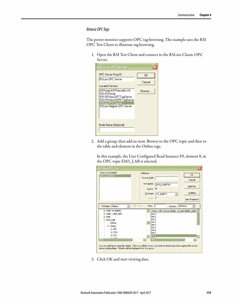
Communication Chapter 4
Browse OPC Tags
The power monitor supports OPC tag browsing. The example uses the RSI OPC Test Client to illustrate tag browsing.
1. Open the RSI Test Client and connect to the RSLinx Classic OPC Server.
2. Add a group, then add an item. Browse to the OPC topic and then to the table and element in the Online tags.
In this example, the User Configured Read Instance F9, element 8, in the OPC topic EM3_LAB is selected.
3. Click OK and start viewing data.
Rockwell Automation Publication 1408-UM002B-EN-P - April 2017 119

Chapter 4 Communication
Notes:
120 Rockwell Automation Publication 1408-UM002B-EN-P - April 2017
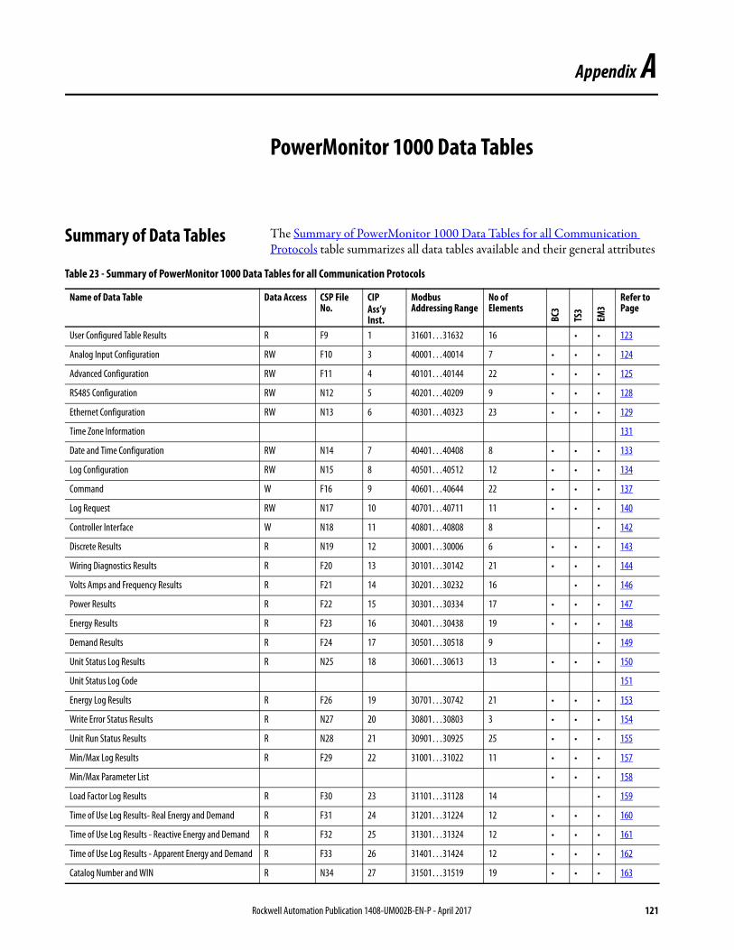
Appendix A
PowerMonitor 1000 Data Tables
Summary of Data Tables The Summary of PowerMonitor 1000 Data Tables for all Communication Protocols table summarizes all data tables available and their general attributes
Table 23 - Summary of PowerMonitor 1000 Data Tables for all Communication Protocols
Name of Data Table Data Access CSP File No.
CIPAss’y Inst.
Modbus Addressing Range
No of Elements
BC3
TS3
EM3
Refer to Page
User Configured Table Results R F9 1 31601…31632 16 • • 123
Analog Input Configuration RW F10 3 40001…40014 7 • • • 124
Advanced Configuration RW F11 4 40101…40144 22 • • • 125
RS485 Configuration RW N12 5 40201…40209 9 • • • 128
Ethernet Configuration RW N13 6 40301…40323 23 • • • 129
Time Zone Information 131
Date and Time Configuration RW N14 7 40401…40408 8 • • • 133
Log Configuration RW N15 8 40501…40512 12 • • • 134
Command W F16 9 40601…40644 22 • • • 137
Log Request RW N17 10 40701…40711 11 • • • 140
Controller Interface W N18 11 40801…40808 8 • 142
Discrete Results R N19 12 30001…30006 6 • • • 143
Wiring Diagnostics Results R F20 13 30101…30142 21 • • • 144
Volts Amps and Frequency Results R F21 14 30201…30232 16 • • 146
Power Results R F22 15 30301…30334 17 • • • 147
Energy Results R F23 16 30401…30438 19 • • • 148
Demand Results R F24 17 30501…30518 9 • 149
Unit Status Log Results R N25 18 30601…30613 13 • • • 150
Unit Status Log Code 151
Energy Log Results R F26 19 30701…30742 21 • • • 153
Write Error Status Results R N27 20 30801…30803 3 • • • 154
Unit Run Status Results R N28 21 30901…30925 25 • • • 155
Min/Max Log Results R F29 22 31001…31022 11 • • • 157
Min/Max Parameter List • • • 158
Load Factor Log Results R F30 23 31101…31128 14 • 159
Time of Use Log Results- Real Energy and Demand R F31 24 31201…31224 12 • • • 160
Time of Use Log Results - Reactive Energy and Demand R F32 25 31301…31324 12 • • • 161
Time of Use Log Results - Apparent Energy and Demand R F33 26 31401…31424 12 • • • 162
Catalog Number and WIN R N34 27 31501…31519 19 • • • 163
Rockwell Automation Publication 1408-UM002B-EN-P - April 2017 121

Appendix A PowerMonitor 1000 Data Tables
Single Element Password Write W N35 28 40901 1 • • • 164
User Configurable Table Setup R/W N44 29 41001…41017 17 • • 165
Parameters for Configurable Table • • 166
Security Policy Configuration R/W N45 30 41101…41115 15 • • • 169
Security Policy Status R N46 31 31901…31901 1 • • • 171
Security UserName W ST47 32 41201…41216 1 • • • 172
Security Password W ST48 33 41301…41316 1 • • • 172
Alarm Status Results R N49 34 31701…31709 9 • 173
Alarm Log Results R N50 35 31801…31808 8 • 174
Alarm Log Code • 175
DF1 PCCC Diagnostic Status Reply • • • 176
Parameter Object Instances • • • 177
Table 23 - Summary of PowerMonitor 1000 Data Tables for all Communication Protocols
Name of Data Table Data Access CSP File No.
CIPAss’y Inst.
Modbus Addressing Range
No of Elements
BC3
TS3
EM3
Refer to Page
122 Rockwell Automation Publication 1408-UM002B-EN-P - April 2017

PowerMonitor 1000 Data Tables Appendix A
Data Tables These tables detail each specific data table and its associated elements, such as Modbus address, default value, ranges, and description.
User Configurable Table Results
IMPORTANTThe lock symbol designates that the parameter that is marked is not be able to be written when the hardware lock terminals are connected together.
Table 24 - Table Properties
CSP File No. F9
CIP Instance 1
Applies to EM3, TS3 only
No. of Elements 16
No. of Words 32
Data Type Float
Data Access Read Only
Table 25 - User Configurable Table Results
Element No. Modbus Address Element Name Description
0 31601-2 User selected Parameter #1 Parameters previously setup during a write to User Configurable Table Setup table.
1 31603-4 User selected Parameter #2
2 31605-6 User selected Parameter #3
3 31607-8 User selected Parameter #4
4 31609-10 User selected Parameter #5
5 31611-12 User selected Parameter #6
6 31613-14 User selected Parameter #7
7 31615-16 User selected Parameter #8
8 31617-18 User selected Parameter #9
9 31619-20 User selected Parameter #10
10 31621-22 User selected Parameter #11
11 31623-24 User selected Parameter #12
12 31625-26 User selected Parameter #13
13 31627-28 User selected Parameter #14
14 31629-30 User selected Parameter #15
15 31631-32 User selected Parameter #16
Rockwell Automation Publication 1408-UM002B-EN-P - April 2017 123

Appendix A PowerMonitor 1000 Data Tables
Analog Input Configuration
Table 26 - Table Properties
CSP File No. F10
CIP Instance 3
Applies to All models
No. of Elements 7
No. of Words 14
Data Type Float
Data Access Read/Write
Table 27 - Analog Input Configuration
Element No. Modbus Address
Element Name Default Value
Range Description
0 40001-2 Table Password 0 0…9999 When the applicable security (web or explicit message) is disabled, this parameter allows the input data from the source to be accepted. If the applicable security is enabled, this parameter is ignored. Returns -1 on a read.
1 40003-4 Voltage Mode 2 0…6 Must match the external electrical system and how it is wired to the power monitor voltage and current input terminals. See page 20 for wiring diagrams.0 = Direct Delta 1 = Open Delta 2 = Wye3 = Split Phase4 = Demo5 = 1PT-1CT LL6 = 1PT-1CT LN
2 40005-6 PT Primary 480 1.00…50,000
The first value of the PT ratio (xxx:xxx) indicating the nominal voltage present at the high-end of the transformer. If no transformer is used (for direct connect of up to 347V L-N or 600V L-L), set the PT ratio to any valid 1:1 ratio (for example 480:480).
3 40007-8 PT Secondary 480 1.00…600.00
The second value of the PT ratio (xxx:xxx) indicating the nominal voltage present at the low-end of the transformer.
4 40009-10 CT Primary 5 5.00…50,000
The first value of the CT ratio (xxx:5) indicating the nominal current present at the high-end (primary side) of the transformer. Example: PRI = 1000. Setting = 1000:5. 5 A is the nominal secondary current of the CT.
5 40011-12 System PF Setting 2 0…2 0 = Leading -97…891 = High -85…982 = Low -52…-95
6 40013-14 Reserved 0 0 Reserved for future use.
124 Rockwell Automation Publication 1408-UM002B-EN-P - April 2017
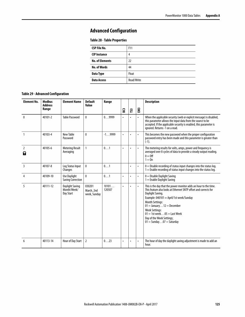
PowerMonitor 1000 Data Tables Appendix A
Advanced Configuration
Table 28 - Table Properties
CSP File No. F11
CIP Instance 4
No. of Elements 22
No. of Words 44
Data Type Float
Data Access Read/Write
Table 29 - Advanced Configuration
Element No. Modbus Address Range
Element Name Default Value
Range
BC3
TS3
EM3
Description
0 40101-2 Table Password 0 0…9999 • • • When the applicable security (web or explicit message) is disabled, this parameter allows the input data from the source to be accepted. If the applicable security is enabled, this parameter is ignored. Returns -1 on a read.
1 40103-4 New Table Password
0 -1…9999 • • • This becomes the new password when the proper configuration password entry has been made and this parameter is greater than (-1).
2 40105-6 Metering Result Averaging
1 0…1 • • • The metering results for volts, amps, power and frequency is averaged over 8 cycles of data to provide a steady output reading.0 = Off1 = On
3 40107-8 Log Status Input Changes
0 0…1 • • 0 = Disable recording of status input changes into the status log.1 = Enable recording of status input changes into the status log.
4 40109-10 Use Daylight Saving Correction
0 0…1 • • • 0 = Disable Daylight Saving1 = Enable Daylight Saving
5 40111-12 Daylight Saving Month/Week/Day Start
030201March, 2nd week, Sunday
10101…120507
• • • This is the day that the power monitor adds an hour to the time. This feature also looks at Ethernet SNTP offset and corrects for Daylight Saving.Example: 040101 = April/1st week/SundayMonth Settings:01 = January…12 = DecemberWeek Settings:01 = 1st week…05 = Last WeekDay of the Week Settings:01 = Sunday…07 = Saturday
6 40113-14 Hour of Day Start 2 0…23 • • • The hour of day the daylight saving adjustment is made to add an hour.
Rockwell Automation Publication 1408-UM002B-EN-P - April 2017 125

Appendix A PowerMonitor 1000 Data Tables
7 40115-16 Return from Daylight Saving Month/Week/Day
110101November, 1st week, Sunday
10101…120507
• • • This is the day that the power monitor subtracts an hour from the time. This feature also looks at Ethernet SNTP offset and corrects for the return from Daylight Saving.Month Settings:01 = January…12 = DecemberWeek Settings:01 = 1st week…05 = Last WeekDay of the Week Settings:01 = Sunday…07 = Saturday
8 40117-18 Hour of Day End 2 0…23 • • • The hour of day the daylight saving adjustment is made to subtract an hour.
9 40119-20 KYZ Solid State Output Parameter
0 0…5 • • The parameter selected pulses the KYZ output at a rate that equals the parameter value divided by KYZ scale.0 = Disable1 = Wh Fwd2 = Wh Rev3 = VARh Fwd4 = VARh Rev5 = Vah
10 40121-22 KYZ Solid State Output Scale
1,000 1…100,000
• • The KYZ output parameter divided by the scale is the output pulse rate. Example: Wh is selected for the parameter and 1,000 is the scale value. The output is pulsed every kWh.
11 40123-24 KYZ Pulse Duration Setting
250 ms 0 or 50…1000
• • Set as 50…1000 to indicate the duration of the pulse in milliseconds, or set to 0 for KYZ-style transition output. (Toggle) The value for delay is rounded off to the nearest 10 ms internally during this function.
12 40125-26 Status Input 1 Input Scale
1 1…1,000,000
• • When a status pulse is received the count is increased by the scale factor. Input pulse * input scale added to total status count.
13 40127-28 Status Input 2 Input Scale
1 1…1,000,000
• • When a status pulse is received the count is increased by the scale factor. Input pulse * input scale added to total status count.
14 40129-30 Demand Source 0 0…3 • When item Demand Broadcast Master Select of the ethernet table is set to master a selection of 0…2 sets the type of master input. In this case item 3 is ignored. When the Demand Broadcast Master Select of the Ethernet table is set to slave then any of these inputs can set the end of the demand period. Selections of 0…2 can be selected for RS485 units.0 = Internal Timer1 = Status Input 22 = Controller Command3 = Ethernet Demand BroadcastSelection 3 can only be programmed when the Ethernet option is installed.
15 40131-32 Demand Period Length
15 min 0…99 • Specifies the desired period for demand calculations. When set to 0 there are no projected demand calculations. If the internal timer is selected a setting of 0 turns the demand function off.
16 40133-34 Number of Demand Periods
1 1…15 • Specifies the number of demand periods to average for demand measurement.
Table 29 - Advanced Configuration
Element No. Modbus Address Range
Element Name Default Value
Range
BC3
TS3
EM3
Description
126 Rockwell Automation Publication 1408-UM002B-EN-P - April 2017
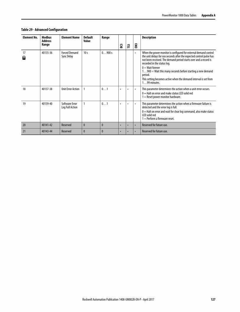
PowerMonitor 1000 Data Tables Appendix A
17 40135-36 Forced Demand Sync Delay
10 s 0…900 s • When the power monitor is configured for external demand control the unit delays for xxx seconds after the expected control pulse has not been received. The demand period starts over and a record is recorded in the status log.0 = Wait forever1…900 = Wait this many seconds before starting a new demand period.This setting becomes active when the demand interval is set from 1…99 minutes.
18 40137-38 Unit Error Action 1 0…1 • • • This parameter determines the action when a unit error occurs.0 = Halt on error and make status LED solid red1 = Reset power monitor hardware.
19 40139-40 Software Error Log Full Action
1 0…1 • • • This parameter determines the action when a firmware failure is detected and the error log is full.0 = Halt on error and wait for clear log command, also make status LED solid red1 = Perform a firmware reset.
20 40141-42 Reserved 0 0 • • • Reserved for future use.
21 40143-44 Reserved 0 0 • • • Reserved for future use.
Table 29 - Advanced Configuration
Element No. Modbus Address Range
Element Name Default Value
Range
BC3
TS3
EM3
Description
Rockwell Automation Publication 1408-UM002B-EN-P - April 2017 127
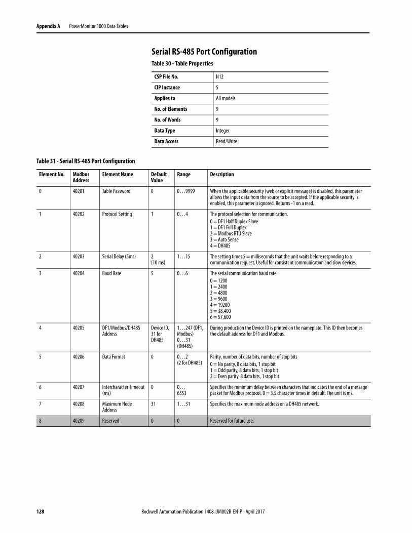
Appendix A PowerMonitor 1000 Data Tables
Serial RS-485 Port ConfigurationTable 30 - Table Properties
CSP File No. N12
CIP Instance 5
Applies to All models
No. of Elements 9
No. of Words 9
Data Type Integer
Data Access Read/Write
Table 31 - Serial RS-485 Port Configuration
Element No. Modbus Address
Element Name Default Value
Range Description
0 40201 Table Password 0 0…9999 When the applicable security (web or explicit message) is disabled, this parameter allows the input data from the source to be accepted. If the applicable security is enabled, this parameter is ignored. Returns -1 on a read.
1 40202 Protocol Setting 1 0…4 The protocol selection for communication.0 = DF1 Half Duplex Slave1 = DF1 Full Duplex2 = Modbus RTU Slave3 = Auto Sense4 = DH485
2 40203 Serial Delay (5ms) 2(10 ms)
1…15 The setting times 5 = milliseconds that the unit waits before responding to a communication request. Useful for consistent communication and slow devices.
3 40204 Baud Rate 5 0…6 The serial communication baud rate.0 = 12001 = 24002 = 48003 = 96004 = 192005 = 38,4006 = 57,600
4 40205 DF1/Modbus/DH485 Address
Device ID, 31 for DH485
1…247 (DF1, Modbus) 0…31 (DH485)
During production the Device ID is printed on the nameplate. This ID then becomes the default address for DF1 and Modbus.
5 40206 Data Format 0 0…2(2 for DH485)
Parity, number of data bits, number of stop bits0 = No parity, 8 data bits, 1 stop bit1 = Odd parity, 8 data bits, 1 stop bit2 = Even parity, 8 data bits, 1 stop bit
6 40207 Intercharacter Timeout (ms)
0 0…6553
Specifies the minimum delay between characters that indicates the end of a message packet for Modbus protocol. 0 = 3.5 character times in default. The unit is ms.
7 40208 Maximum Node Address
31 1…31 Specifies the maximum node address on a DH485 network.
8 40209 Reserved 0 0 Reserved for future use.
128 Rockwell Automation Publication 1408-UM002B-EN-P - April 2017
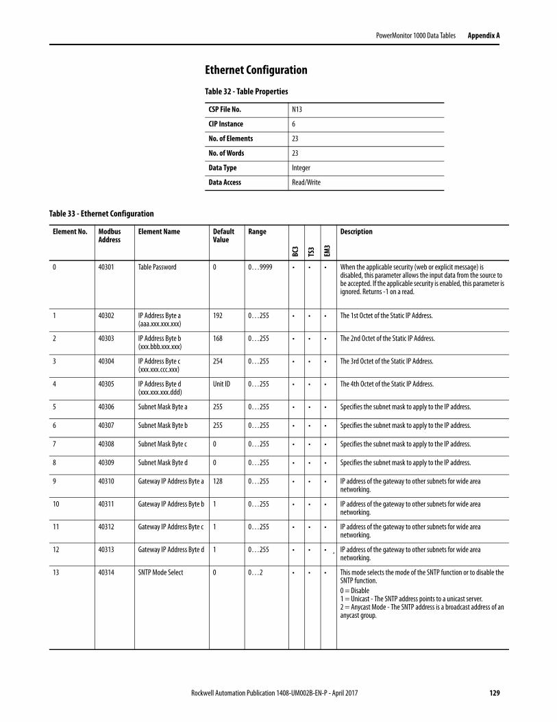
PowerMonitor 1000 Data Tables Appendix A
Ethernet Configuration
Table 32 - Table Properties
CSP File No. N13
CIP Instance 6
No. of Elements 23
No. of Words 23
Data Type Integer
Data Access Read/Write
Table 33 - Ethernet Configuration
Element No. Modbus Address
Element Name Default Value
Range
BC3
TS3
EM3
Description
0 40301 Table Password 0 0…9999 • • • When the applicable security (web or explicit message) is disabled, this parameter allows the input data from the source to be accepted. If the applicable security is enabled, this parameter is ignored. Returns -1 on a read.
1 40302 IP Address Byte a (aaa.xxx.xxx.xxx)
192 0…255 • • • The 1st Octet of the Static IP Address.
2 40303 IP Address Byte b (xxx.bbb.xxx.xxx)
168 0…255 • • • The 2nd Octet of the Static IP Address.
3 40304 IP Address Byte c (xxx.xxx.ccc.xxx)
254 0…255 • • • The 3rd Octet of the Static IP Address.
4 40305 IP Address Byte d (xxx.xxx.xxx.ddd)
Unit ID 0…255 • • • The 4th Octet of the Static IP Address.
5 40306 Subnet Mask Byte a 255 0…255 • • • Specifies the subnet mask to apply to the IP address.
6 40307 Subnet Mask Byte b 255 0…255 • • • Specifies the subnet mask to apply to the IP address.
7 40308 Subnet Mask Byte c 0 0…255 • • • Specifies the subnet mask to apply to the IP address.
8 40309 Subnet Mask Byte d 0 0…255 • • • Specifies the subnet mask to apply to the IP address.
9 40310 Gateway IP Address Byte a 128 0…255 • • • IP address of the gateway to other subnets for wide area networking.
10 40311 Gateway IP Address Byte b 1 0…255 • • • IP address of the gateway to other subnets for wide area networking.
11 40312 Gateway IP Address Byte c 1 0…255 • • • IP address of the gateway to other subnets for wide area networking.
12 40313 Gateway IP Address Byte d 1 0…255 • • • ¸ IP address of the gateway to other subnets for wide area networking.
13 40314 SNTP Mode Select 0 0…2 • • • This mode selects the mode of the SNTP function or to disable the SNTP function.0 = Disable1 = Unicast - The SNTP address points to a unicast server.2 = Anycast Mode - The SNTP address is a broadcast address of an anycast group.
Rockwell Automation Publication 1408-UM002B-EN-P - April 2017 129
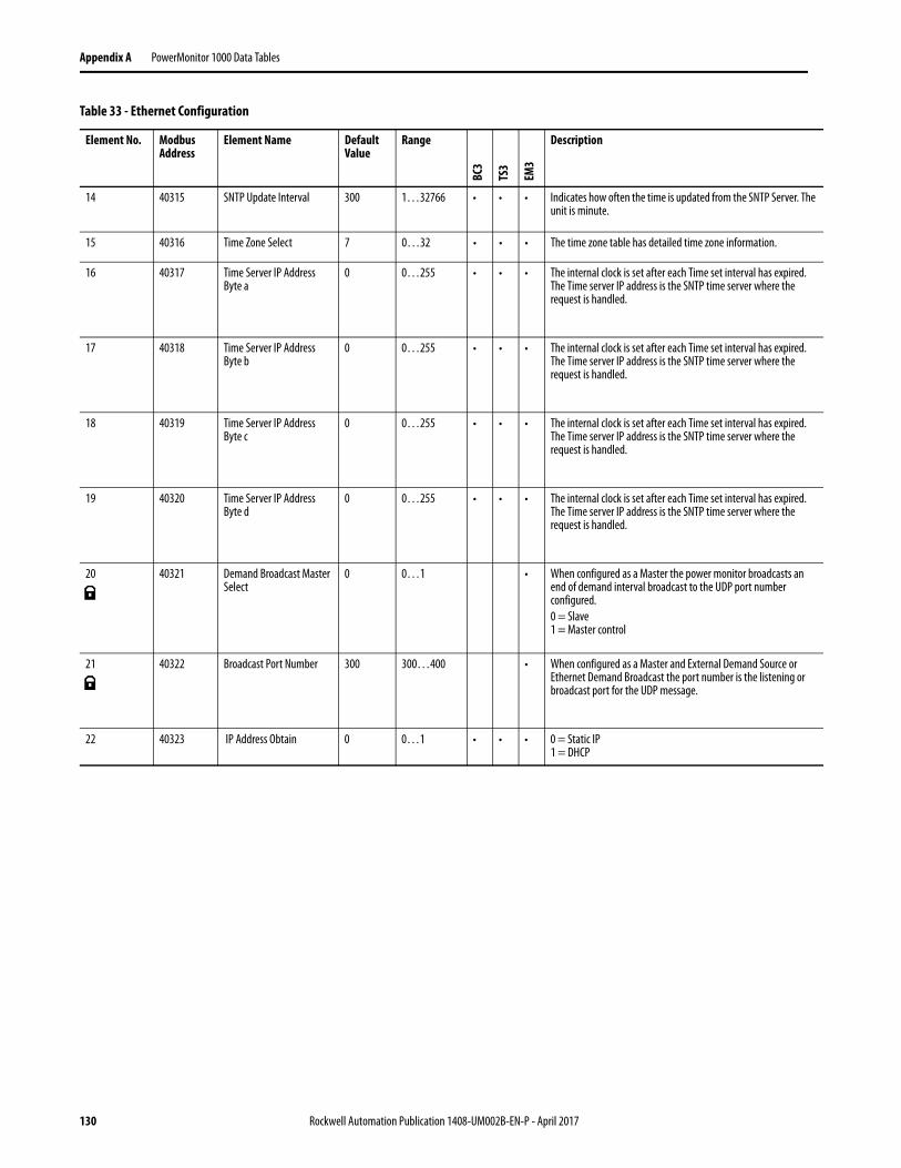
Appendix A PowerMonitor 1000 Data Tables
14 40315 SNTP Update Interval 300 1…32766 • • • Indicates how often the time is updated from the SNTP Server. The unit is minute.
15 40316 Time Zone Select 7 0…32 • • • The time zone table has detailed time zone information.
16 40317 Time Server IP Address Byte a
0 0…255 • • • The internal clock is set after each Time set interval has expired. The Time server IP address is the SNTP time server where the request is handled.
17 40318 Time Server IP Address Byte b
0 0…255 • • • The internal clock is set after each Time set interval has expired. The Time server IP address is the SNTP time server where the request is handled.
18 40319 Time Server IP Address Byte c
0 0…255 • • • The internal clock is set after each Time set interval has expired. The Time server IP address is the SNTP time server where the request is handled.
19 40320 Time Server IP Address Byte d
0 0…255 • • • The internal clock is set after each Time set interval has expired. The Time server IP address is the SNTP time server where the request is handled.
20 40321 Demand Broadcast Master Select
0 0…1 • When configured as a Master the power monitor broadcasts an end of demand interval broadcast to the UDP port number configured.0 = Slave1 = Master control
21 40322 Broadcast Port Number 300 300…400 • When configured as a Master and External Demand Source or Ethernet Demand Broadcast the port number is the listening or broadcast port for the UDP message.
22 40323 IP Address Obtain 0 0…1 • • • 0 = Static IP1 = DHCP
Table 33 - Ethernet Configuration
Element No. Modbus Address
Element Name Default Value
Range
BC3
TS3
EM3
Description
130 Rockwell Automation Publication 1408-UM002B-EN-P - April 2017
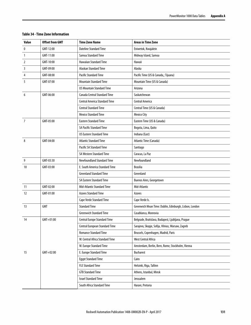
PowerMonitor 1000 Data Tables Appendix A
Table 34 - Time Zone Information
Value Offset from GMT Time Zone Name Areas in Time Zone
0 GMT-12:00 Dateline Standard Time Eniwetok, Kwajalein
1 GMT-11:00 Samoa Standard Time Midway Island, Samoa
2 GMT-10:00 Hawaiian Standard Time Hawaii
3 GMT-09:00 Alaskan Standard Time Alaska
4 GMT-08:00 Pacific Standard Time Pacific Time (US & Canada,; Tijuana)
5 GMT-07:00 Mountain Standard Time Mountain Time (US & Canada)
US Mountain Standard Time Arizona
6 GMT-06:00 Canada Central Standard Time Saskatchewan
Central America Standard Time Central America
Central Standard Time Central Time (US & Canada)
Mexico Standard Time Mexico City
7 GMT-05:00 Eastern Standard Time Eastern Time (US & Canada)
SA Pacific Standard Time Bogota, Lima, Quito
US Eastern Standard Time Indiana (East)
8 GMT-04:00 Atlantic Standard Time Atlantic Time (Canada)
Pacific SA Standard Time Santiago
SA Western Standard Time Caracas, La Paz
9 GMT-03:30 Newfoundland Standard Time Newfoundland
10 GMT-03:00 E. South America Standard Time Brasilia
Greenland Standard Time Greenland
SA Eastern Standard Time Buenos Aires, Georgetown
11 GMT-02:00 Mid-Atlantic Standard Time Mid-Atlantic
12 GMT-01:00 Azores Standard Time Azores
Cape Verde Standard Time Cape Verde Is.
13 GMT Standard Time Greenwich Mean Time: Dublin, Edinburgh, Lisbon, London
Greenwich Standard Time Casablanca, Monrovia
14 GMT+01:00 Central Europe Standard Time Belgrade, Bratislava, Budapest, Ljubljana, Prague
Central European Standard Time Sarajevo, Skopje, Sofija, Vilnius, Warsaw, Zagreb
Romance Standard Time Brussels, Copenhagen, Madrid, Paris
W. Central Africa Standard Time West Central Africa
W. Europe Standard Time Amsterdam, Berlin, Bern, Rome, Stockholm, Vienna
15 GMT+02:00 E. Europe Standard Time Bucharest
Egypt Standard Time Cairo
FLE Standard Time Helsinki, Riga, Tallinn
GTB Standard Time Athens, Istanbul, Minsk
Israel Standard Time Jerusalem
South Africa Standard Time Harare, Pretoria
Rockwell Automation Publication 1408-UM002B-EN-P - April 2017 131
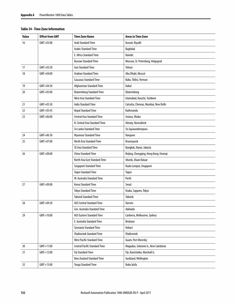
Appendix A PowerMonitor 1000 Data Tables
16 GMT+03:00 Arab Standard Time Kuwait, Riyadh
Arabic Standard Time Baghdad
E. Africa Standard Time Nairobi
Russian Standard Time Moscow, St. Petersburg, Volgograd
17 GMT+03:30 Iran Standard Time Tehran
18 GMT+04:00 Arabian Standard Time Abu Dhabi, Muscat
Caucasus Standard Time Baku, Tbilisi, Yerevan
19 GMT+04:30 Afghanistan Standard Time Kabul
20 GMT+05:00 Ekaterinburg Standard Time Ekaterinburg
West Asia Standard Time Islamabad, Karachi, Tashkent
21 GMT+05:30 India Standard Time Calcutta, Chennai, Mumbai, New Delhi
22 GMT+05:45 Nepal Standard Time Kathmandu
23 GMT+06:00 Central Asia Standard Time Astana, Dhaka
N. Central Asia Standard Time Almaty, Novosibirsk
Sri Lanka Standard Time Sri Jayawardenepura
24 GMT+06:30 Myanmar Standard Time Rangoon
25 GMT+07:00 North Asia Standard Time Krasnoyarsk
SE Asia Standard Time Bangkok, Hanoi, Jakarta
26 GMT+08:00 China Standard Time Beijing, Chongqing, Hong Kong, Urumqi
North Asia East Standard Time Irkutsk, Ulaan Bataar
Singapore Standard Time Kuala Lumpur, Singapore
Taipei Standard Time Taipei
W. Australia Standard Time Perth
27 GMT+09:00 Korea Standard Time Seoul
Tokyo Standard Time Osaka, Sapporo, Tokyo
Yakutsk Standard Time Yakutsk
28 GMT+09:30 AUS Central Standard Time Darwin
Cen. Australia Standard Time Adelaide
29 GMT+10:00 AUS Eastern Standard Time Canberra, Melbourne, Sydney
E. Australia Standard Time Brisbane
Tasmania Standard Time Hobart
Vladivostok Standard Time Vladivostok
West Pacific Standard Time Guam, Port Moresby
30 GMT+11:00 Central Pacific Standard Time Magadan, Solomon Is., New Caledonia
31 GMT+12:00 Fiji Standard Time Fiji, Kamchatka, Marshall Is.
New Zealand Standard Time Auckland, Wellington
32 GMT+13:00 Tonga Standard Time Nuku'alofa
Table 34 - Time Zone Information
Value Offset from GMT Time Zone Name Areas in Time Zone
132 Rockwell Automation Publication 1408-UM002B-EN-P - April 2017
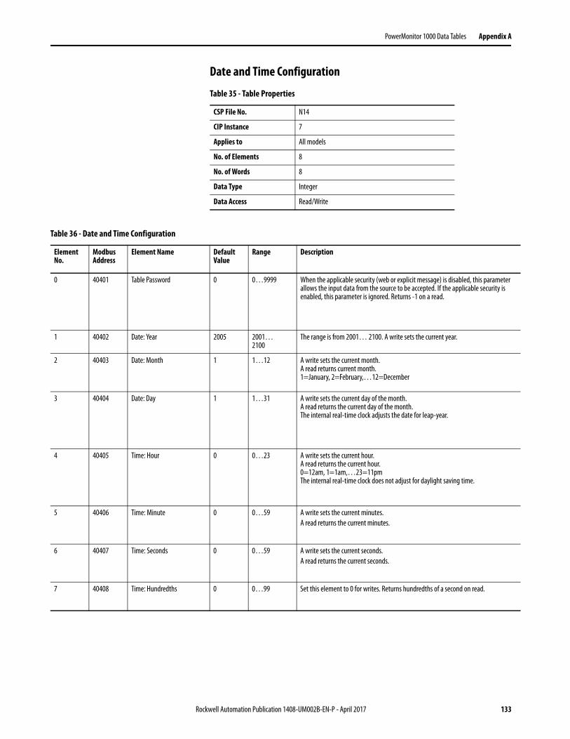
PowerMonitor 1000 Data Tables Appendix A
Date and Time Configuration
Table 35 - Table Properties
CSP File No. N14
CIP Instance 7
Applies to All models
No. of Elements 8
No. of Words 8
Data Type Integer
Data Access Read/Write
Table 36 - Date and Time Configuration
Element No.
Modbus Address
Element Name Default Value
Range Description
0 40401 Table Password 0 0…9999 When the applicable security (web or explicit message) is disabled, this parameter allows the input data from the source to be accepted. If the applicable security is enabled, this parameter is ignored. Returns -1 on a read.
1 40402 Date: Year 2005 2001…2100
The range is from 2001… 2100. A write sets the current year.
2 40403 Date: Month 1 1…12 A write sets the current month.A read returns current month.1=January, 2=February,…12=December
3 40404 Date: Day 1 1…31 A write sets the current day of the month.A read returns the current day of the month.The internal real-time clock adjusts the date for leap-year.
4 40405 Time: Hour 0 0…23 A write sets the current hour. A read returns the current hour. 0=12am, 1=1am,…23=11pmThe internal real-time clock does not adjust for daylight saving time.
5 40406 Time: Minute 0 0…59 A write sets the current minutes.A read returns the current minutes.
6 40407 Time: Seconds 0 0…59 A write sets the current seconds.A read returns the current seconds.
7 40408 Time: Hundredths 0 0…99 Set this element to 0 for writes. Returns hundredths of a second on read.
Rockwell Automation Publication 1408-UM002B-EN-P - April 2017 133

Appendix A PowerMonitor 1000 Data Tables
Log Configuration
Table 37 - Table Properties
CSP File No. N15
CIP Instance 8
No. of Elements 12
No. of Words 12
Data Type Integer
Data Access Read/Write
Table 38 - Log Configuration
Element No. Modbus Address
Element Name Default Value
Range
BC3
TS3
EM3
Description
0 40501 Table Password 0 0…9999
• • • When the applicable security (web or explicit message) is disabled, this parameter allows the input data from the source to be accepted. If the applicable security is enabled, this parameter is ignored. Returns -1 on a read.
1 40502 Energy Log Interval 15 min -1…600...60 (BC3,TS3)
• • • Selects how often a record is logged (minutes). A value of 0 disables periodic logging of records. A value of –1 causes logging of records to be synchronized to the end of the demand interval.
2 40503 Energy Log Mode 1 0…1 • • • This parameter sets the action of the log once it has filled to capacity. Setting the option to 0 allows the log to fill but stops at the end. Option 1 lets the log fill and then oldest records are deleted and replaced with new records.0 = Fill and Stop1 = Overwrite, When the log is filled new records replace the oldest records.
3 40504 Time of Use Log Auto Log Setting
31 0…31 • • • Automatically stores the current record for the month replacing the oldest record if the log is full. The log holds 12 months plus the current record.0 = Disables the auto clear feature.1 = Store and clear the table on the 1st day of each month.2 = 2nd Day3 = 3rd day…29…31 = Store and clear table at the last day of the month.
4 40505 Off Peak Days 65 0…127 • • • This bit map field selects the off peak days. OFF-PEAK days have only one rate for billing.Bit0= SundayBit1= MondayBit2= TuesdayBit3= WednesdayBit4= ThursdayBit5= FridayBit6= SaturdaySaturday and Sunday are default Off Peak days.
134 Rockwell Automation Publication 1408-UM002B-EN-P - April 2017

PowerMonitor 1000 Data Tables Appendix A
5 40506 MID Peak AM Hours 1792 0…4095
• • • This bit map selects any AM hours that are designated as MID Peak. Example: The hours from 8 AM to 11AM is designated as bit 8 through bit 10 = 1792d.Bit0= 12 AM…1 AMBit1= 1 AM…2 AMBit2= 2 AM…3 AM……Bit11= 11AM…12 PMDefault is 8 AM…11 AM
6 40507 MID Peak PM Hours 120 0…4095
• • • This bit map selects any PM hours that are designated as MID Peak. Example: The hours from 3 PM to 7 PM is designated as bit 3 through bit 6 = 120d.Bit0= 12 PM…1 PMBit1= 1 PM…2 PMBit2= 2 PM…3 PM……Bit11= 11PM…12 AMDefault is 3 PM…7 PM
7 40508 ON Peak AM Hours 2048 0…4095
• • • This bit map selects any AM hours that are designated as ON Peak. Example: The hours from 11AM to 12 PM is designated as bit 11 = 2048d.Bit0= 12 AM…1 AMBit1= 1 AM…2 AMBit2= 2 AM…3 AM…Bit11= 11AM…12 PMDefault is 11AM
8 40509 ON Peak PM hours 7 0…4095 • • • This bit map selects any PM hours that are designated as ON Peak. Example: The hours from 12 PM to 3 PM is designated as bit 0 through bit 2 = 7dBit0= 12 PM…1 PMBit1= 1 PM…2 PMBit2= 2 PM…3 PM…Bit11= 11PM…12 AMDefault is 12 PM…3 PM
9 40510 Load Factor log Auto Log Setting
31 0…31 • Automatically stores the current peak, average, and load factor results as a record in the non-volatile load factor log and resets the log at the specified day of the month.0 = Disables the auto clear feature.1 = Store and clear the table on the 1st day of each month.2 = 2nd Day3 = 3rd day…29…31 = Store and clear table at the last day of the month.
Table 38 - Log Configuration
Element No. Modbus Address
Element Name Default Value
Range
BC3
TS3
EM3
Description
Rockwell Automation Publication 1408-UM002B-EN-P - April 2017 135

Appendix A PowerMonitor 1000 Data Tables
10 40511 Reserved 0 0 • • • Reserved for future use.
11 40512 Reserved 0 0 • • • Reserved for future use.
Table 38 - Log Configuration
Element No. Modbus Address
Element Name Default Value
Range
BC3
TS3
EM3
Description
136 Rockwell Automation Publication 1408-UM002B-EN-P - April 2017
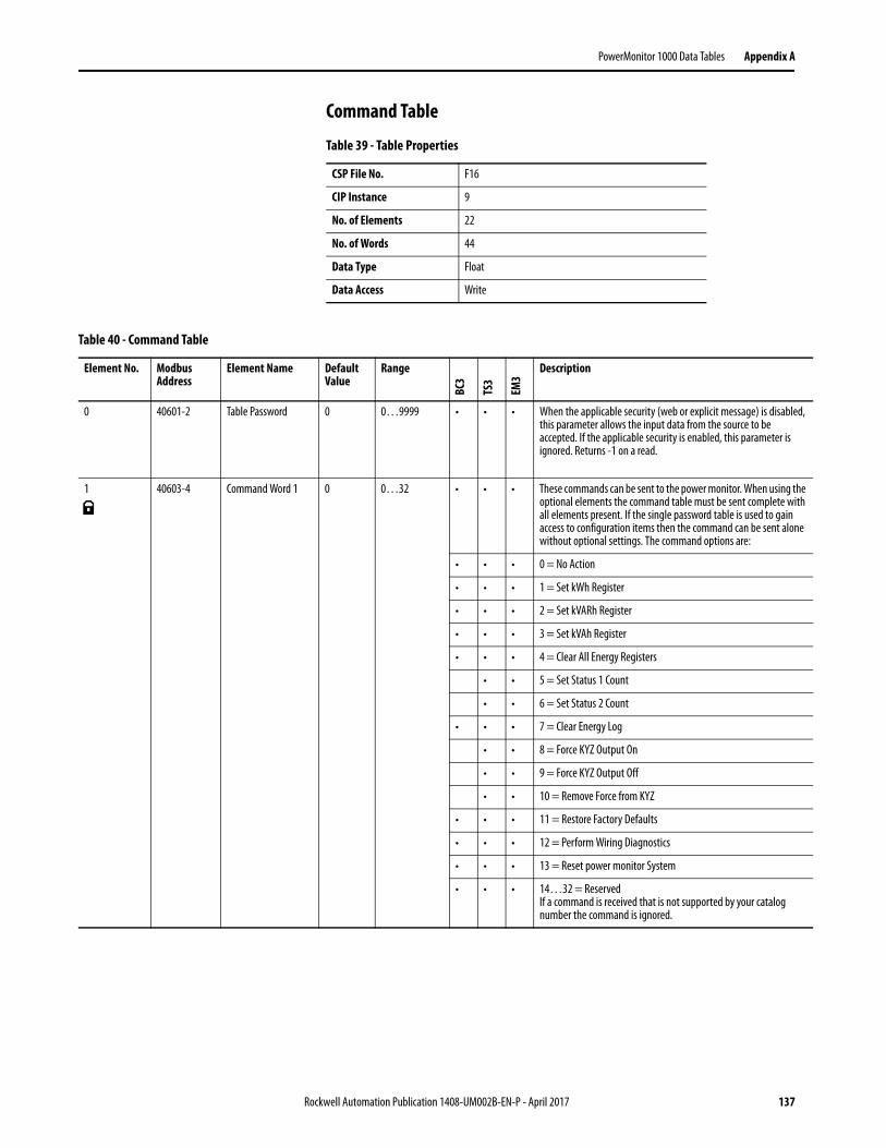
PowerMonitor 1000 Data Tables Appendix A
Command Table
Table 39 - Table Properties
CSP File No. F16
CIP Instance 9
No. of Elements 22
No. of Words 44
Data Type Float
Data Access Write
Table 40 - Command Table
Element No. Modbus Address
Element Name Default Value
Range
BC3
TS3
EM3
Description
0 40601-2 Table Password 0 0…9999 • • • When the applicable security (web or explicit message) is disabled, this parameter allows the input data from the source to be accepted. If the applicable security is enabled, this parameter is ignored. Returns -1 on a read.
1 40603-4 Command Word 1 0 0…32 • • • These commands can be sent to the power monitor. When using the optional elements the command table must be sent complete with all elements present. If the single password table is used to gain access to configuration items then the command can be sent alone without optional settings. The command options are:
• • • 0 = No Action
• • • 1 = Set kWh Register
• • • 2 = Set kVARh Register
• • • 3 = Set kVAh Register
• • • 4 = Clear All Energy Registers
• • 5 = Set Status 1 Count
• • 6 = Set Status 2 Count
• • • 7 = Clear Energy Log
• • 8 = Force KYZ Output On
• • 9 = Force KYZ Output Off
• • 10 = Remove Force from KYZ
• • • 11 = Restore Factory Defaults
• • • 12 = Perform Wiring Diagnostics
• • • 13 = Reset power monitor System
• • • 14…32 = ReservedIf a command is received that is not supported by your catalog number the command is ignored.
Rockwell Automation Publication 1408-UM002B-EN-P - April 2017 137
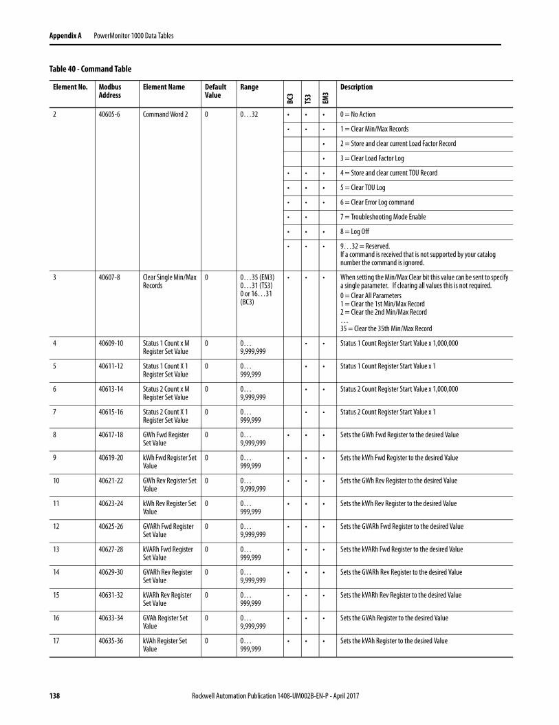
Appendix A PowerMonitor 1000 Data Tables
2 40605-6 Command Word 2 0 0…32 • • • 0 = No Action
• • • 1 = Clear Min/Max Records
• 2 = Store and clear current Load Factor Record
• 3 = Clear Load Factor Log
• • • 4 = Store and clear current TOU Record
• • • 5 = Clear TOU Log
• • • 6 = Clear Error Log command
• • 7 = Troubleshooting Mode Enable
• • • 8 = Log Off
• • • 9…32 = Reserved.If a command is received that is not supported by your catalog number the command is ignored.
3 40607-8 Clear Single Min/Max Records
0 0…35 (EM3)0…31 (TS3)0 or 16…31 (BC3)
• • • When setting the Min/Max Clear bit this value can be sent to specify a single parameter. If clearing all values this is not required.0 = Clear All Parameters1 = Clear the 1st Min/Max Record2 = Clear the 2nd Min/Max Record…35 = Clear the 35th Min/Max Record
4 40609-10 Status 1 Count x M Register Set Value
0 0…9,999,999
• • Status 1 Count Register Start Value x 1,000,000
5 40611-12 Status 1 Count X 1 Register Set Value
0 0…999,999
• • Status 1 Count Register Start Value x 1
6 40613-14 Status 2 Count x M Register Set Value
0 0…9,999,999
• • Status 2 Count Register Start Value x 1,000,000
7 40615-16 Status 2 Count X 1 Register Set Value
0 0…999,999
• • Status 2 Count Register Start Value x 1
8 40617-18 GWh Fwd Register Set Value
0 0…9,999,999
• • • Sets the GWh Fwd Register to the desired Value
9 40619-20 kWh Fwd Register Set Value
0 0…999,999
• • • Sets the kWh Fwd Register to the desired Value
10 40621-22 GWh Rev Register Set Value
0 0…9,999,999
• • • Sets the GWh Rev Register to the desired Value
11 40623-24 kWh Rev Register Set Value
0 0…999,999
• • • Sets the kWh Rev Register to the desired Value
12 40625-26 GVARh Fwd Register Set Value
0 0…9,999,999
• • • Sets the GVARh Fwd Register to the desired Value
13 40627-28 kVARh Fwd Register Set Value
0 0…999,999
• • • Sets the kVARh Fwd Register to the desired Value
14 40629-30 GVARh Rev Register Set Value
0 0…9,999,999
• • • Sets the GVARh Rev Register to the desired Value
15 40631-32 kVARh Rev Register Set Value
0 0…999,999
• • • Sets the kVARh Rev Register to the desired Value
16 40633-34 GVAh Register Set Value
0 0…9,999,999
• • • Sets the GVAh Register to the desired Value
17 40635-36 kVAh Register Set Value
0 0…999,999
• • • Sets the kVAh Register to the desired Value
Table 40 - Command Table
Element No. Modbus Address
Element Name Default Value
Range
BC3
TS3
EM3
Description
138 Rockwell Automation Publication 1408-UM002B-EN-P - April 2017

PowerMonitor 1000 Data Tables Appendix A
18 40637-38 Troubleshooting Mode Password
0 0 • • • Password for Troubleshooting Mode provided by Rockwell Automation.
19 40639-40 Reserved 0 0 • • • Reserved for future use.
20 40641-42 Reserved 0 0 • • • Reserved for future use.
21 40643-44 Reserved 0 0 • • • Reserved for future use.
Table 40 - Command Table
Element No. Modbus Address
Element Name Default Value
Range
BC3
TS3
EM3
Description
Rockwell Automation Publication 1408-UM002B-EN-P - April 2017 139

Appendix A PowerMonitor 1000 Data Tables
Log Request TableTable 41 - Table Properties
CSP File No. N17
CIP Instance 10
No. of Elements 11
No. of Words 11
Data Type Integer
Data Access Read/Write
Table 42 - Log Request Table
Element No.
Modbus Address
Element Name Default Value
Range
BC3
TS3
EM3
Description
0 40701 Selected Log 0 0…9 • • • Selects the log that information is returned from. Once a single request has been made, the auto return feature brings back successive records each time the log is read. Some logs support individual record requests. IMPORTANT: If your catalog number does not support the requested log item, the power monitor ignores the request.
• • • 0 = No Log Selected
• • • 1 = Unit Status Log
• • • 2 = Min/Max Log
• • • 3 = Energy Log
• 4 = Load Factor Log
• • • 5 = Time of Use Log kWh
• • • 6 = Time of Use Log kVARh
• • • 7 = Time of Use Log kVAh
• • • 8 = Internal Error Log
• 9 = Alarm Log
1 40702 Chronology of Auto Return Data
1 0…1 • • • The date chronology of the returned records.0 = Reverse direction1 = Forward direction
2 40703 The Min/Max record to be returned
0 0…35 (EM3)0…31 (TS3)0 or 16…31 (BC3)
• • • Selects the Min/Max record number to be returned. See the table for Min/Max record list.0 = Use incremental return and the chronology selected.
3 40704 Number of Unit Status Records
- 1…50 • • • On a read of this table the value of this parameter is the number of Unit Status Records available. This log is only returned using the incremental return method.
4 40705 Number of Energy Log Records
- 0…17,280
• • • On a read of this table the value of this parameter is the number of Energy Log Records available.
140 Rockwell Automation Publication 1408-UM002B-EN-P - April 2017
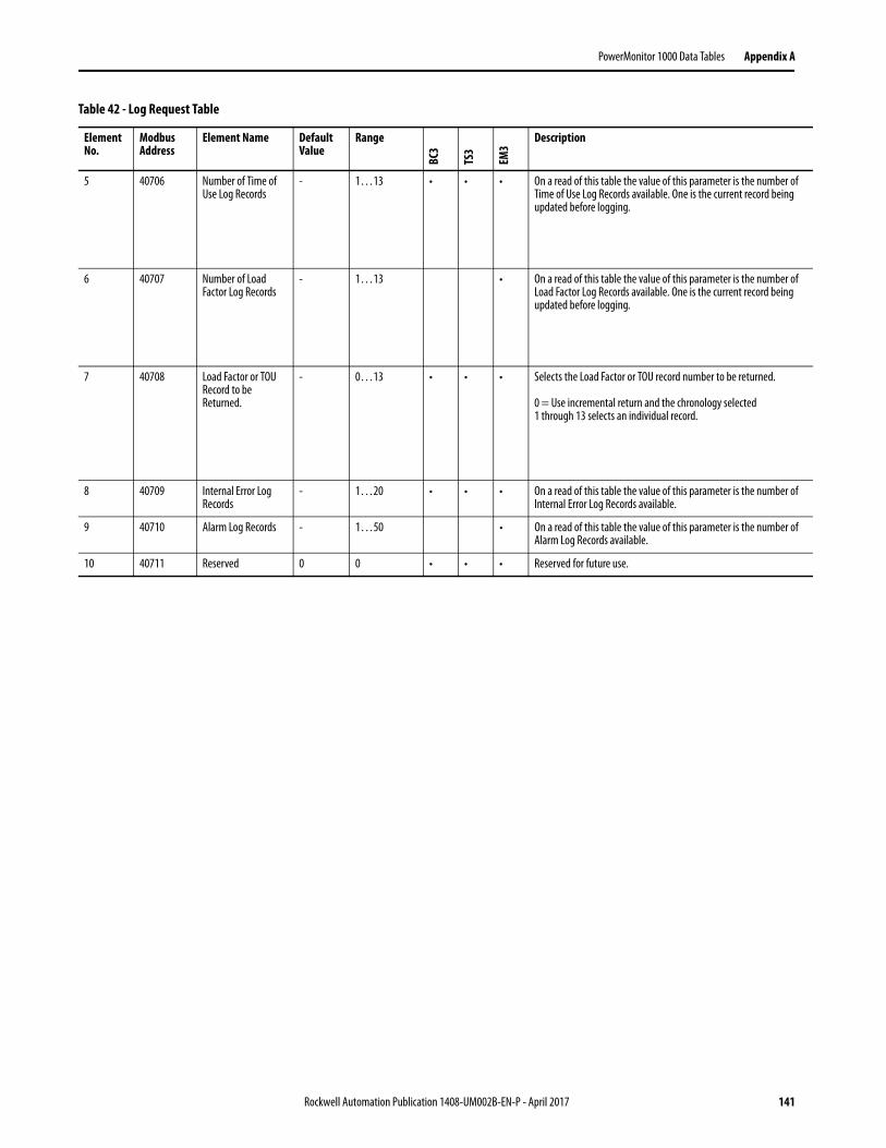
PowerMonitor 1000 Data Tables Appendix A
5 40706 Number of Time of Use Log Records
- 1…13 • • • On a read of this table the value of this parameter is the number of Time of Use Log Records available. One is the current record being updated before logging.
6 40707 Number of Load Factor Log Records
- 1…13 • On a read of this table the value of this parameter is the number of Load Factor Log Records available. One is the current record being updated before logging.
7 40708 Load Factor or TOU Record to be Returned.
- 0…13 • • • Selects the Load Factor or TOU record number to be returned.
0 = Use incremental return and the chronology selected1 through 13 selects an individual record.
8 40709 Internal Error Log Records
- 1…20 • • • On a read of this table the value of this parameter is the number of Internal Error Log Records available.
9 40710 Alarm Log Records - 1…50 • On a read of this table the value of this parameter is the number of Alarm Log Records available.
10 40711 Reserved 0 0 • • • Reserved for future use.
Table 42 - Log Request Table
Element No.
Modbus Address
Element Name Default Value
Range
BC3
TS3
EM3
Description
Rockwell Automation Publication 1408-UM002B-EN-P - April 2017 141

Appendix A PowerMonitor 1000 Data Tables
Controller Interface TableTable 43 - Table Properties
CSP File No. N18
CIP Instance 11
Applies to EM3 only
No. of Elements 8
No. of Words 8
Data Type Integer
Data Access Write
Table 44 - Controller Interface Table
Element No. Modbus Address
Element Name Default Value
Range Description
0 40801 Table Password 0 0…9999 When the applicable security (web or explicit message) is disabled, this parameter allows the input data from the source to be accepted. If the applicable security is enabled, this parameter is ignored. Returns -1 on a read.
1 40802 Controller Command Word
0 0…1 Bit 0 = When this bit is written to the power monitor it signals the end of the demand period. The power monitor resets the bit to 0 and sends the end of demand broadcast to all of the slaves configured for the master/slave demand system. The power monitor must be configured as a Master for external demand pulse input.Bit 1…15 = Reserved
2 40803 Reserved 0 0 Reserved for future use.
3 40804 Reserved 0 0 Reserved for future use.
4 40805 Reserved 0 0 Reserved for future use.
5 40806 Reserved 0 0 Reserved for future use.
6 40807 Reserved 0 0 Reserved for future use.
7 40808 Reserved 0 0 Reserved for future use.
142 Rockwell Automation Publication 1408-UM002B-EN-P - April 2017

PowerMonitor 1000 Data Tables Appendix A
Discrete ResultsTable 45 - Table Properties
CSP File No. N19
CIP Instance 12
Applies to All models
No. of Elements 6
No. of Words 6
Data Type Integer
Data Access Read
Table 46 - Discrete Results
Element No.
Modbus Address
Element Name Range Description
0(1) 30001 Status Input States 0…3 Indicates the current states of the status input.Bit 0 = Status 1 activatedBit 1 = Status 2 activatedBit 2…15 = Reserved
1(2) 30002 Output Word 0…31 Bit 0 = KYZ relay actuatedBit 1 = KYZ output forced onBit 2 = KYZ output forced offBit 3 = External demand pulse timeoutBit 4 = Terminal LockedBit 5…15 = Reserved
2 30003 Reserved 0 Reserved for future use.
3 30004 Reserved 0 Reserved for future use.
4 30005 Reserved 0 Reserved for future use.
5 30006 Reserved 0 Reserved for future use.
(1) Element 0 is not available for BC3.
(2) Only Bit 4 supported on BC3 model.
Rockwell Automation Publication 1408-UM002B-EN-P - April 2017 143

Appendix A PowerMonitor 1000 Data Tables
Wiring Diagnostics ResultsTable 47 - Table Properties
CSP File No. F20
CIP Instance 13
No. of Elements 21
No. of Words 42
Data Type Float
Data Access Read
Table 48 - Wiring Diagnostics Results
Element No.
Modbus Address
Element Name Units Range
BC3
TS3
EM3
Description
0 30101-2 Wiring Status 0…5 • • • This is the overall status of the wiring diagnostic test.0 = Pass1 = Failed2 = Input Level Low3 = Disabled4 = Waiting Command5 = Out of range
1 30103-4 Voltage Input Missing -1…123 • • • Reports on all three phases.-1 = Test not run.0 = Test passed.1 = Phase 1 missing2 = Phase 2 missing3 = Phase 3 missing12 = Phase 1 and 2 missing13 = Phase 1 and 3 missing23 = Phase 2 and 3 missing123 = All phases missing
2 30105-6 Voltage Input Inverted -1…123 • • • Reports on all three phases.-1 = Test not run.0 = Test passed.1 = Phase 1 inverted2 = Phase 2 inverted3 = Phase 3 inverted12 = Phase 1 and 2 inverted13 = Phase 1 and 3 inverted23 = Phase 2 and 3 inverted123 = All phases inverted
3 30107-8 Current Input Missing -1…123 • • • Reports on all three phases.-1 = Test not run.0 = Test passed.1 = Phase 1 missing2 = Phase 2 missing3 = Phase 3 missing12 = Phase 1 and 2 missing13 = Phase 1 and 3 missing23 = Phase 2 and 3 missing123 = All phases missing
144 Rockwell Automation Publication 1408-UM002B-EN-P - April 2017
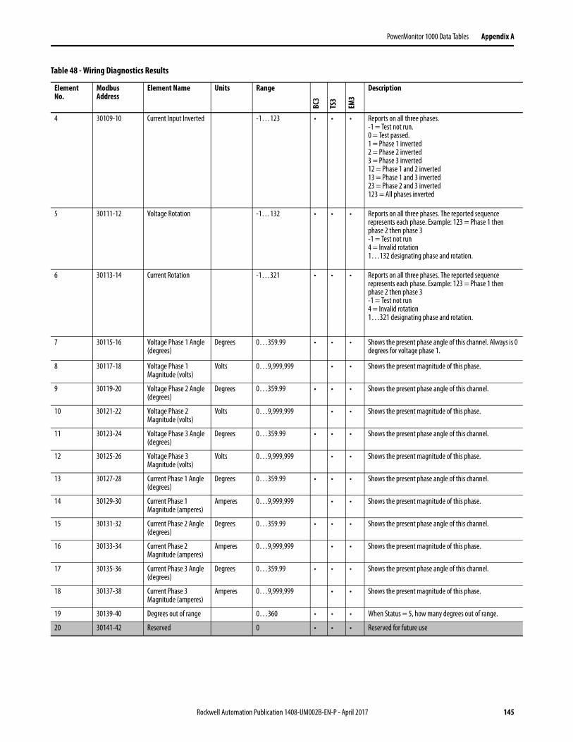
PowerMonitor 1000 Data Tables Appendix A
4 30109-10 Current Input Inverted -1…123 • • • Reports on all three phases.-1 = Test not run.0 = Test passed.1 = Phase 1 inverted2 = Phase 2 inverted3 = Phase 3 inverted12 = Phase 1 and 2 inverted13 = Phase 1 and 3 inverted23 = Phase 2 and 3 inverted123 = All phases inverted
5 30111-12 Voltage Rotation -1…132 • • • Reports on all three phases. The reported sequence represents each phase. Example: 123 = Phase 1 then phase 2 then phase 3-1 = Test not run4 = Invalid rotation1…132 designating phase and rotation.
6 30113-14 Current Rotation -1…321 • • • Reports on all three phases. The reported sequence represents each phase. Example: 123 = Phase 1 then phase 2 then phase 3-1 = Test not run4 = Invalid rotation1…321 designating phase and rotation.
7 30115-16 Voltage Phase 1 Angle (degrees)
Degrees 0…359.99 • • • Shows the present phase angle of this channel. Always is 0 degrees for voltage phase 1.
8 30117-18 Voltage Phase 1 Magnitude (volts)
Volts 0…9,999,999 • • Shows the present magnitude of this phase.
9 30119-20 Voltage Phase 2 Angle (degrees)
Degrees 0…359.99 • • • Shows the present phase angle of this channel.
10 30121-22 Voltage Phase 2 Magnitude (volts)
Volts 0…9,999,999 • • Shows the present magnitude of this phase.
11 30123-24 Voltage Phase 3 Angle (degrees)
Degrees 0…359.99 • • • Shows the present phase angle of this channel.
12 30125-26 Voltage Phase 3 Magnitude (volts)
Volts 0…9,999,999 • • Shows the present magnitude of this phase.
13 30127-28 Current Phase 1 Angle (degrees)
Degrees 0…359.99 • • • Shows the present phase angle of this channel.
14 30129-30 Current Phase 1 Magnitude (amperes)
Amperes 0…9,999,999 • • Shows the present magnitude of this phase.
15 30131-32 Current Phase 2 Angle (degrees)
Degrees 0…359.99 • • • Shows the present phase angle of this channel.
16 30133-34 Current Phase 2 Magnitude (amperes)
Amperes 0…9,999,999 • • Shows the present magnitude of this phase.
17 30135-36 Current Phase 3 Angle (degrees)
Degrees 0…359.99 • • • Shows the present phase angle of this channel.
18 30137-38 Current Phase 3 Magnitude (amperes)
Amperes 0…9,999,999 • • Shows the present magnitude of this phase.
19 30139-40 Degrees out of range 0…360 • • • When Status = 5, how many degrees out of range.
20 30141-42 Reserved 0 • • • Reserved for future use
Table 48 - Wiring Diagnostics Results
Element No.
Modbus Address
Element Name Units Range
BC3
TS3
EM3
Description
Rockwell Automation Publication 1408-UM002B-EN-P - April 2017 145

Appendix A PowerMonitor 1000 Data Tables
Volts Amps Frequency ResultsTable 49 - Table Properties
CSP File No. F21
CIP Instance 14
No. of Elements 16
No. of Words 32
Data Type Float
Data Access Read
Table 50 - Volts Amps Frequency Results
Element No. Modbus Address
Element Name Range
BC3
TS3
EM3
Description
0 30201-2 L1 Current 0.000…9,999,999 • • Phase 1 scaled RMS Current
1 30203-4 L2 Current 0.000…9,999,999 • • Phase 2 scaled RMS Current
2 30205-6 L3 Current 0.000…9,999,999 • • Phase 3 scaled RMS Current
3 30207-8 Average Current 0.000…9,999,999 • • Average RMS Current
4 30209-10 L1-N Volts 0.000…9,999,999 • • Phase 1 scaled RMS Voltage
5 30211-12 L2-N Volts 0.000…9,999,999 • • Phase 2 scaled RMS Voltage
6 30213-14 L3-N Volts 0.000…9,999,999 • • Phase 3 scaled RMS Voltage
7 30215-16 Average L-N Volts 0.000…9,999,999 • • Averaged RMS Voltage
8 30217-18 L1-L2 Volts 0.000…9,999,999 • • Line 1 to Line 2 Volts
9 30219-20 L2-L3 Volts 0.000…9,999,999 • • Line 2 to Line 3 Volts
10 30221-22 L3-L1 Volts 0.000…9,999,999 • • Line 3 to Line 1 Volts
11 30223-24 Average L-L Volts 0.000…9,999,999 • • Average Line to Line Volts
12 30225-26 Frequency 40.0 Hz…70.0 Hz • • Last frequency reading.
13 30227-28 Percent Current Unbalance 0.0…100.0 • • Percent maximum deviation from Ave. / Ave.
14 30229-30 Percent Voltage Unbalance 0.0…100.0 • • Percent Maximum deviation from Ave. / Ave.
15 30231-32 Metering Iteration 0…9,999,999 • • Increments by 1 for each new metering calculation.
146 Rockwell Automation Publication 1408-UM002B-EN-P - April 2017

PowerMonitor 1000 Data Tables Appendix A
Power ResultsTable 51 - Table Properties
CSP File No. F22
CIP Instance 15
No. of Elements 17
No. of Words 34
Data Type Float
Data Access Read
Table 52 - Power Results
Element No.
Modbus Address
Element Name Range
BC3
TS3
EM3
Description
0 30301-2 L1 True Power Factor -100.0…+100.0 • • • Percent ratio between power and apparent power. The value is signed to (+) leading and (-) lagging.
1 30303-4 L2 True Power Factor -100.0…+100.0 • • •
2 30305-6 L3 True Power Factor -100.0…+100.0 • • •
3 30307-8 3 Phase True Power Factor
-100.0…+100.0 • • •
4 30309-10 L1 kW ± 0.000…9,999,999 • • • Line 1 kW
5 30311-12 L2 kW ± 0.000…9,999,999 • • • Line 2 kW
6 30313-14 L3 kW ± 0.000…9,999,999 • • • Line 3 kW
7 30315-16 Total kW ± 0.000…9,999,999 • • • Total kW
8 30317-18 L1 kVAR ± 0.000…9,999,999 • • • Line 1 kVAR
9 30319-20 L2 kVAR ± 0.000…9,999,999 • • • Line 2 kVAR
10 30321-22 L3 kVAR ± 0.000…9,999,999 • • • Line 3 kVAR
11 30323-24 Total kVAR ± 0.000…9,999,999 • • • Total kVAR
12 30325-26 L1 kVA 0.000…9,999,999 • • • Line 1 kVA
13 30327-28 L2 kVA 0.000…9,999,999 • • • Line 2 kVA
14 30329-30 L3 kVA 0.000…9,999,999 • • • Line 3 kVA
15 30331-32 Total kVA 0.000…9,999,999 • • • Total kVA
16 30333-34 Metering Iteration 0…9,999,999 • • • Increments by 1 for each new metering calculation.
IMPORTANT Only total power values are returned in delta wiring modes. Zeroes are returned for individual phase values.
Rockwell Automation Publication 1408-UM002B-EN-P - April 2017 147
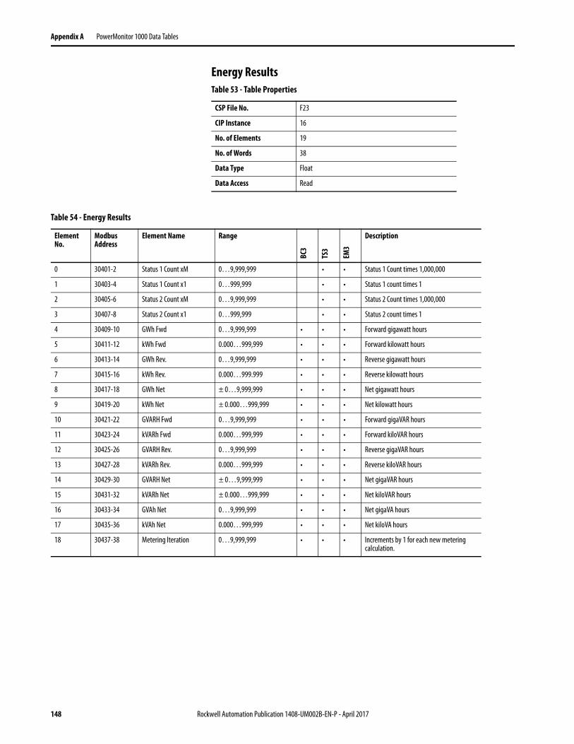
Appendix A PowerMonitor 1000 Data Tables
Energy ResultsTable 53 - Table Properties
CSP File No. F23
CIP Instance 16
No. of Elements 19
No. of Words 38
Data Type Float
Data Access Read
Table 54 - Energy Results
Element No.
Modbus Address
Element Name Range
BC3
TS3
EM3
Description
0 30401-2 Status 1 Count xM 0…9,999,999 • • Status 1 Count times 1,000,000
1 30403-4 Status 1 Count x1 0…999,999 • • Status 1 count times 1
2 30405-6 Status 2 Count xM 0…9,999,999 • • Status 2 Count times 1,000,000
3 30407-8 Status 2 Count x1 0…999,999 • • Status 2 count times 1
4 30409-10 GWh Fwd 0…9,999,999 • • • Forward gigawatt hours
5 30411-12 kWh Fwd 0.000…999,999 • • • Forward kilowatt hours
6 30413-14 GWh Rev. 0…9,999,999 • • • Reverse gigawatt hours
7 30415-16 kWh Rev. 0.000…999.999 • • • Reverse kilowatt hours
8 30417-18 GWh Net ± 0…9,999,999 • • • Net gigawatt hours
9 30419-20 kWh Net ± 0.000…999,999 • • • Net kilowatt hours
10 30421-22 GVARH Fwd 0…9,999,999 • • • Forward gigaVAR hours
11 30423-24 kVARh Fwd 0.000…999,999 • • • Forward kiloVAR hours
12 30425-26 GVARH Rev. 0…9,999,999 • • • Reverse gigaVAR hours
13 30427-28 kVARh Rev. 0.000…999,999 • • • Reverse kiloVAR hours
14 30429-30 GVARH Net ± 0…9,999,999 • • • Net gigaVAR hours
15 30431-32 kVARh Net ± 0.000…999,999 • • • Net kiloVAR hours
16 30433-34 GVAh Net 0…9,999,999 • • • Net gigaVA hours
17 30435-36 kVAh Net 0.000…999,999 • • • Net kiloVA hours
18 30437-38 Metering Iteration 0…9,999,999 • • • Increments by 1 for each new metering calculation.
148 Rockwell Automation Publication 1408-UM002B-EN-P - April 2017

PowerMonitor 1000 Data Tables Appendix A
Demand ResultsTable 55 - Table Properties
CSP File No. F24
CIP Instance 17
No. of Elements 9
No. of Words 18
Data Type Float
Data Access Read
Table 56 - Demand Results
Element No.
Modbus Address
Element Name Range
BC3
TS3
EM3
Description
0 30501-2 kW Demand ± 0.000…9,999,999 • The average real power during the last demand period.
1 30503-4 kVAR Demand ± 0.000…9,999,999 • The average reactive power during the last demand period.
2 30505-6 kVA Demand 0.000…9,999,999 • The average apparent power during the last demand period.
3 30507-8 Demand PF -100.0…+100.0 • The average demand for PF during the last demand period.
4 30509-10 Projected kW Demand ± 0.000…9,999,999 • The projected total real power for the current period.
5 30511-12 Projected kVAR Demand ± 0.000…9,999,999 • The projected total reactive power for the current period.
6 30513-14 Projected kVA Demand 0.000…9,999,999 • The projected total apparent power for the current period.
7 30515-16 Elapsed Demand Period Time
0.00…99.99 • The amount of time that has elapsed during the current period.
8 30517-18 Metering Iteration 0…9,999,999 • Increments by 1 for each new metering calculation.
Rockwell Automation Publication 1408-UM002B-EN-P - April 2017 149

Appendix A PowerMonitor 1000 Data Tables
Unit Status Log ResultsTable 57 - Table Properties
CSP File No. N25
CIP Instance 18
Applies to All models
No. of Elements 13
No. of Words 13
Data Type Integer
Data Access Read
Table 58 - Unit Status Log Results
Element No. Modbus Address
Element Name Range Description
0 30601 Status Record Internal Identifier 1…50 Used to verify record sequence when returning multiple records.
1 30602 Timestamp Year of record - The year when the record was recorded.
2 30603 Timestamp Month/Day - The month and day when the record was recorded.
3 30604 Timestamp Hour/Minute - The hour and minute when the record was recorded.
4 30605 Timestamp Seconds/Hundredths - The seconds and hundredths when the record was recorded.
5 30606 Status Event Type 0…512 Indicates the type of status event that has occurred.
6 30607 General Code 0…4096 Indicates general information about the status event.
7 30608 Information Code 0…256 Indicates specific information about the status event.
8 30609 Reserved 0 Reserved for future use.
9 30610 Reserved 0 Reserved for future use.
10 30611 Reserved 0 Reserved for future use.
11 30612 Reserved 0 Reserved for future use.
12 30613 Reserved 0 Reserved for future use.
150 Rockwell Automation Publication 1408-UM002B-EN-P - April 2017

PowerMonitor 1000 Data Tables Appendix A
Table 59 - Unit Status Log Codes
Status Event Type (Decimal)
Event # General Code (Decimal) Code # Information Code (Decimal)
BC3
TS3
EM3 Code
#
Self Test Status 1 Pass 0 • • •
Flash Memory 1 Overall Status • • • 1
Boot Code Checksum • • • 2
Application Code Checksum • • • 4
Calibration Data CRC • • • 8
No Calibration Data • • • 16
Wrong Application FRN • • • 32
Invalid Model Type • • • 64
WIN Mismatch • • • 128
Missing Upgrade Block • • • 256
SRAM 2 Failed Read/Write Test • • • 1
NVRAM 4 Failed Read/Write Test • • • 1
SPI Interface 8 SPI Device Not Responding • • • 1
SPI Interface Failed • • • 2
Real Time Clock 16 Real Time Clock Failed • • • 1
Real Time Clock not Set • • • 2
Watchdog Timer 32 Watchdog Time Out • • • 1
Metering 64 Metering Status Failed • • • 1
LCD Interface 128 LCD Interface Failure • • 1
Serial Communication 256 Serial Communication Port Failed • • • 1
Ethernet Communication 512 Ethernet Communication Port Failed • • • 1
Modbus Stack Initialization Failed • • • 2
Demand Broadcast Thread Init Failed • 4
SNTP Thread Init Failed • • • 8
Input Over Range 1024 Input Over Range Voltage • • • 1
Input Over Range Current • • • 2
Voltage Phase Loss 2048 Voltage Channel 1 Loss • • • 1
Voltage Channel 2 Loss • • • 2
Voltage Channel 3 Loss • • • 4
Process Error 4096 • • •
Rockwell Automation Publication 1408-UM002B-EN-P - April 2017 151
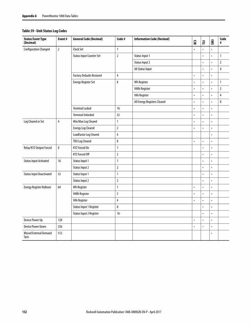
Appendix A PowerMonitor 1000 Data Tables
Configuration Changed 2 Clock Set 1 • • •
Status Input Counter Set 2 Status Input 1 • • 1
Status Input 2 • • 2
All Status Input • • 4
Factory Defaults Restored 4 • • •
Energy Register Set 8 Wh Register • • • 1
VARh Register • • • 2
VAh Register • • • 4
All Energy Registers Cleared • • • 8
Terminal Locked 16 • • •
Terminal Unlocked 32 • • •
Log Cleared or Set 4 Min/Max Log Cleared 1 • • •
Energy Log Cleared 2 • • •
LoadFactor Log Cleared 4 •
TOU Log Cleared 8 • • •
Relay/KYZ Output Forced 8 KYZ Forced On 1 • •
KYZ Forced Off 2 • •
Status Input Activated 16 Status Input 1 1 • •
Status Input 2 2 • •
Status Input Deactivated 32 Status Input 1 1 • •
Status Input 2 2 • •
Energy Register Rollover 64 Wh Register 1 • • •
VARh Register 2 • • •
VAh Register 4 • • •
Status Input 1 Register 8 • •
Status Input 2 Register 16 • •
Device Power Up 128 • • •
Device Power Down 256 • • •
Missed External Demand Sync
512 •
Table 59 - Unit Status Log Codes
Status Event Type (Decimal)
Event # General Code (Decimal) Code # Information Code (Decimal)
BC3
TS3
EM3 Code
#
152 Rockwell Automation Publication 1408-UM002B-EN-P - April 2017

PowerMonitor 1000 Data Tables Appendix A
Energy Log ResultsTable 60 - Table Properties
CSP File No. F26
CIP Instance 19
No. of Elements 21
No. of Words 42
Data Type Float
Data Access Read
Table 61 - Energy Log Results
Element No.
Modbus Address
Element Name Range
BC3
TS3
EM3
Description
0 30701-2 Internal Record Identifier. • • • Used to verify record sequence when returning multiple records.
1 30703-4 Timestamp Year of record - • • • The date and time when the record was recorded.
2 30705-6 Timestamp Month/Day - • • •
3 30707-8 Timestamp Hour/Minute - • • •
4 30709-10 Timestamp Seconds/Hundredths
- • • •
5 30711-12 Status 1 Count xM 0…9,999,999 • • Status 1 Count times 1,000,000
6 30713-14 Status 1 Count x1 0…999,999 • • Status 1 count times 1
7 30715-16 Status 2 Count xM 0…9,999,999 • • Status 2 Count times 1,000,000
8 30717-18 Status 2 Count x1 0…999,999 • • Status 2 count times 1
9 30719-20 GWh Net ± 0…9,999,999 • • • Net gigawatt hours
10 30721-22 kWh Net ± 0.000…999,999 • • • Net kilowatt hours
11 30723-24 GVARH Net ± 0…9,999,999 • • • Net gigaVAR hours
12 30725-26 kVARh Net ± 0.000…999,999 • • • Net kiloVAR hours
13 30727-28 GVAh Net 0…9,999,999 • • • Net gigaVA hours
14 30729-30 kVAh Net 0.000…999,999 • • • Net kiloVA hours
15 30731-32 kW Demand ± 0.000…9,999,999 • The average real power during the last demand period.
16 30733-34 kVAR Demand ± 0.000…9,999,999 • The average reactive power during the last demand period.
17 30735-36 kVA Demand 0.000…9,999,999 • The average apparent power during the last demand period.
18 30737-38 Demand PF -100.0…+100.0 • The average demand for PF during the last demand period.
19 30739-40 Reserved 0 • • • Reserved for future use.
20 30741-42 Reserved 0 • • • Reserved for future use.
Rockwell Automation Publication 1408-UM002B-EN-P - April 2017 153

Appendix A PowerMonitor 1000 Data Tables
Write Error Status ResultsTable 62 - Table Properties
CSP File No. N27
CIP Instance 20
Applies to All Models
No. of Elements 3
No. of Words 3
Data Type Integer
Data Access Read
Table 63 - Write Error Status Results
Element No.
Modbus Address
Element Name Range Description
0 30801 Table Number or Instance All Write Enabled Tables Indicates the last table that was written.
1 30802 Offending Element Length of current table - 1 If the most recent write was successful this returns a (-1). If the write was unsuccessful this is the first rejected element in the table write.
2 30803 Write Error Status Word 0…32767 Bit 0 = Configuration_Lock_OnBit 1 = Password_is_not_validatedBit 2 = Admin_Name_Or_Password_RejectedBit 3 = Admin_Password_ActiveBit 4 = Application_Name_Or_Password_RejectedBit 5 = Application_Password_ActiveBit 6 = Web_Security_Status
0: Web security disabled1: Web security enabled
Bit 7 = Application_Security_Status0: Application security disabled1: Application security enabled
154 Rockwell Automation Publication 1408-UM002B-EN-P - April 2017
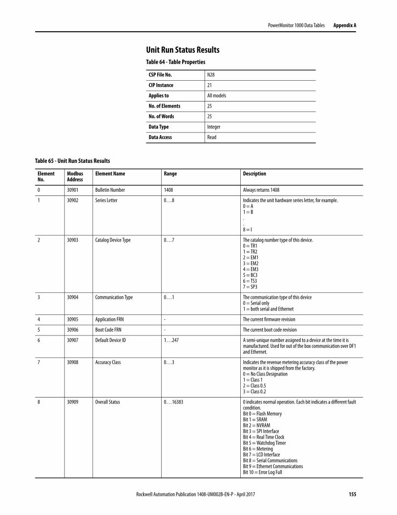
PowerMonitor 1000 Data Tables Appendix A
Unit Run Status ResultsTable 64 - Table Properties
CSP File No. N28
CIP Instance 21
Applies to All models
No. of Elements 25
No. of Words 25
Data Type Integer
Data Access Read
Table 65 - Unit Run Status Results
Element No.
Modbus Address
Element Name Range Description
0 30901 Bulletin Number 1408 Always returns 1408
1 30902 Series Letter 0…8 Indicates the unit hardware series letter, for example.0 = A1 = B..8 = I
2 30903 Catalog Device Type 0…7 The catalog number type of this device.0 = TR11 = TR22 = EM13 = EM24 = EM35 = BC36 = TS37 = SP3
3 30904 Communication Type 0…1 The communication type of this device0 = Serial only1 = both serial and Ethernet
4 30905 Application FRN - The current firmware revision
5 30906 Boot Code FRN - The current boot code revision
6 30907 Default Device ID 1…247 A semi-unique number assigned to a device at the time it is manufactured. Used for out of the box communication over DF1 and Ethernet.
7 30908 Accuracy Class 0…3 Indicates the revenue metering accuracy class of the power monitor as it is shipped from the factory.0 = No Class Designation1 = Class 12 = Class 0.53 = Class 0.2
8 30909 Overall Status 0…16383 0 indicates normal operation. Each bit indicates a different fault condition.Bit 0 = Flash MemoryBit 1 = SRAMBit 2 = NVRAMBit 3 = SPI InterfaceBit 4 = Real Time ClockBit 5 = Watchdog TimerBit 6 = MeteringBit 7 = LCD InterfaceBit 8 = Serial CommunicationsBit 9 = Ethernet CommunicationsBit 10 = Error Log Full
Rockwell Automation Publication 1408-UM002B-EN-P - April 2017 155

Appendix A PowerMonitor 1000 Data Tables
9 30910 Flash Memory 0…511 0 indicates normal operation. Status bits areBit 0 = Overall statusBit 1 = Boot code checksumBit 2 = Application code checksumBit 3 = Calibration data CRCBit 4 = No calibration dataBit 5 = Wrong application FRNBit 6 = Invalid model typeBit 7 = WIN mismatchBit 8 = missing upgrade block
10 30911 SRAM 0…1 0 indicates normal operation. Bit 0 = Read/write test
11 30912 NVRAM 0…1 0 indicates normal operation. Bit 0 = Read/write test
12 30913 SPI Interface 0…1 0 indicates normal operation.Bit 0 = SPI device not responding
13 30914 Real Time Clock 0…3 0 indicates normal operation.Bit 0 = RTC statusBit 1 = Time Zone Set Failed
14 30915 Watchdog Timer 0…1 0 indicates normal operation. Bit 0 = Watchdog time out
15 30916 Metering 0…1 0 indicates normal operation. Bit 0 = Metering status
16 30917 LCD Interface 0…1 0 indicates normal operation.Bit 0 = LCD Interface status
17 30918 Serial Communications 0…1 0 indicates normal operation.Bit 0 = Serial Interface status
18 30919 Ethernet Communications 0…511 0 indicates normal operation.Bit 0 = Ethernet Communications statusBit 1 = SNTP Server timeout statusBit 2 = Duplicate IP Address statusBit 3 = Invalid IP/Netmask addressBit 4 = Invalid gateway addressBit 5 = Invalid SNTP time server addressBit 6 = Modbus stack run statusBit 7 = Demand broadcast thread run statusBit 8 = SNTP thread run status
19 30920 Input Over Range 0…3 0 indicates normal operation.Bit 0 = Voltage Input over rangeBit 1 = Current Input over range
20 30921 Phase Loss Detection 0…7 0 Indicates normal running condition.Bit 0 = Loss of phase ABit 1 = Loss of phase BBit 2 = Loss of phase C
21 30922 Configuration Locked 0…1 Reports 1 if configuration lock is applied.
22 30923 Single Element Password Accepted 0…1 1 indicates the single element password is verified and active
23 30924 Error Recorded 0…20 Is incremented by 1 when an internal error happens
24 30925 Troubleshooting Mode Times Left 0…30 Remaining times for troubleshooting mode.
Table 65 - Unit Run Status Results
Element No.
Modbus Address
Element Name Range Description
156 Rockwell Automation Publication 1408-UM002B-EN-P - April 2017

PowerMonitor 1000 Data Tables Appendix A
Min/Max Log ResultsTable 66 - Table Properties
CSP File No. F29
CIP Instance 22
Applies to All models
No. of Elements 11
No. of Words 22
Data Type Float
Data Access Read
Table 67 - Min/Max Log Results
Element No.
Modbus Address
Element Name Range Description
0 31001-2 Parameter Being Returned 1…35 Indicates the Parameter Number (See Min/Max Parameter List).
1 31003-4 MIN Value ± 0.000…9,999,999 The minimum value recorded for parameter being returned since the last clear command.
2 31005-6 MAX Value ± 0.000…9,999,999 The maximum value recorded for parameter being returned since the last clear command.
3 31007-8 Timestamp Year of MIN The year when the MIN value was recorded.
4 31009-10 Timestamp Month/Day of MIN The month and day when the MIN value was recorded.
5 31011-12 Timestamp Hour/Minute of MIN The hour and minute when the MIN value was recorded.
6 31013-14 Timestamp Seconds/ Hundredths of MIN
The seconds and hundredths when the MIN value was recorded.
7 31015-16 Timestamp Year of MAX The year when the MAX value was recorded.
8 31017-18 Timestamp Month/Day of MAX The month and day when the MAX value was recorded.
9 31019-20 Timestamp Hour/Minute of MAX The hour and minute when the MAX value was recorded.
10 31021-22 Timestamp Seconds/ Hundredths of MAX
The seconds and hundredths when the MAX value was recorded.
Rockwell Automation Publication 1408-UM002B-EN-P - April 2017 157
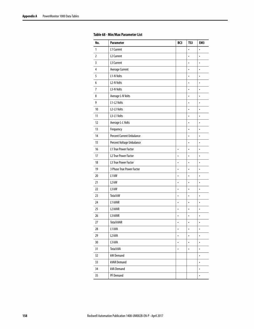
Appendix A PowerMonitor 1000 Data Tables
Table 68 - Min/Max Parameter List
No. Parameter BC3 TS3 EM3
1 L1 Current • •
2 L2 Current • •
3 L3 Current • •
4 Average Current • •
5 L1-N Volts • •
6 L2-N Volts • •
7 L3-N Volts • •
8 Average L-N Volts • •
9 L1-L2 Volts • •
10 L2-L3 Volts • •
11 L3-L1 Volts • •
12 Average L-L Volts • •
13 Frequency • •
14 Percent Current Unbalance • •
15 Percent Voltage Unbalance • •
16 L1 True Power Factor • • •
17 L2 True Power Factor • • •
18 L3 True Power Factor • • •
19 3 Phase True Power Factor • • •
20 L1 kW • • •
21 L2 kW • • •
22 L3 kW • • •
23 Total kW • • •
24 L1 kVAR • • •
25 L2 kVAR • • •
26 L3 kVAR • • •
27 Total kVAR • • •
28 L1 kVA • • •
29 L2 kVA • • •
30 L3 kVA • • •
31 Total kVA • • •
32 kW Demand •
33 kVAR Demand •
34 kVA Demand •
35 PF Demand •
158 Rockwell Automation Publication 1408-UM002B-EN-P - April 2017

PowerMonitor 1000 Data Tables Appendix A
Load Factor Log ResultsTable 69 - Table Properties
CSP File No. F30
CIP Instance 23
Applies to EM3 only
No. of Elements 14
No. of Words 28
Data Type Float
Data Access Read
Table 70 - Load Factor Log Results
Element No.
Modbus Address
Element Name Range Description
0 31101-2 Record Number 1…13 The record number of this data.
1 31103-4 End Date yy/mm/dd - The date that this record was stored.
2 31105-6 Elapsed Time 0.000…9,999,999
Amount of time (in hours) that has elapsed since the last clear of the peak and average values. Updated at the end of each demand interval.
3 31107-8 Peak Demand kW ± 0.000…9,999,999 The largest magnitude demand for kwatts that occurred over all of the demand intervals since the last clear command or auto-clear day.
4 31109-10 Average Demand kW ± 0.000…9,999,999 A running average of demand for kwatts from the end of each demand period since the last clear command or auto-clear day.
5 31111-12 Load Factor kW 0…100% Average Demand kW / Peak Demand kW. This is a demand management metric that indicates how ‘spiky’ (or ‘level’) a load is over a period of time (usually 1 month). A value approaching 100% indicates a constant load.
6 31113-14 Peak Demand kVAR ± 0.000…9,999,999
The largest magnitude demand for kVAR that occurred over all of the demand intervals since the last clear command or auto-clear day.
7 31115-16 Average Demand kVAR ± 0.000…9,999,999
A running average of demand for kVAR from the end of each demand period since the last clear command or auto-clear day.
8 31117-18 Load Factor kVAR 0…100% Average Demand kVAR / Peak Demand kVAR. This is a demand management metric that indicates how ‘spiky’ (or ‘level’) a load is over a period of time (usually 1 month). A value approaching 100% indicates a constant load.
9 31119-20 Peak Demand kVA 0.000…9,999,999
The largest magnitude demand for kVA that occurred over all of the demand intervals since the last clear command or auto-clear day.
10 31121-22 Average Demand kVA 0.000…9,999,999
A running average of demand for kVA from the end of each demand period since the last clear command or auto-clear day.
11 31123-24 Load Factor kVA 0…100% Average Demand kVA / Peak Demand kVA. This is a demand management metric that indicates how ‘spiky’ (or ‘level’) a load is over a period of time (usually 1 month). A value approaching 100% indicates a constant load.
12 31125-26 Reserved 0 Reserved for Future Use
13 31127-28 Reserved 0 Reserved for Future Use
Rockwell Automation Publication 1408-UM002B-EN-P - April 2017 159

Appendix A PowerMonitor 1000 Data Tables
Time of Use Log Results - Real Energy and DemandTable 71 - Table Properties
CSP File No. F31
CIP Instance 24
No. of Elements 12
No. of Words 24
Data Type Float
Data Access Read
Table 72 - Time of Use Log Results - Real Energy and Demand
Element No.
Modbus Address
Element Name Range
BC3
TS3
EM3
Description
0 31201-2 Record Number 1…13 • • • The record number of the log. Record 1 is always the current record before being logged.
1 31203-4 Time Stamp Start Date (yy/mm/dd)
- • • • The Date this record was started.
2 31205-6 Time Stamp End Date (yy/mm/dd)
- • • • The Date this record was ended.
3 31207-8 Off Peak GWh Net ± 0…9,999,999
• • • Net Off Peak gigawatt hours
4 31209-10 Off Peak kWh Net ± 0.000…999,999
• • • Net Off Peak kilowatt hours
5 31211-12 Off Peak kW Demand ± 0.000…9,999,999
• Off Peak Demand for kilowatts
6 31213-14 Mid Peak GWh Net ± 0…9,999,999
• • • Net Mid Peak gigawatt hours
7 31215-16 Mid Peak kWh Net ± 0.000…999,999
• • • Net Mid Peak kilowatt hours
8 31217-18 Mid Peak kW Demand ± 0.000…9,999,999
• Mid Peak Demand for kilowatts
9 31219-20 On Peak GWh Net ± 0.000…9,999,999
• • • Net On Peak gigawatt hours
10 31221-22 On Peak kWh Net ± 0…999,999
• • • Net On Peak kilowatt hours
11 31223-24 On Peak kW Demand ± 0.000…9,999,999
• On Peak Demand for kilowatts
160 Rockwell Automation Publication 1408-UM002B-EN-P - April 2017
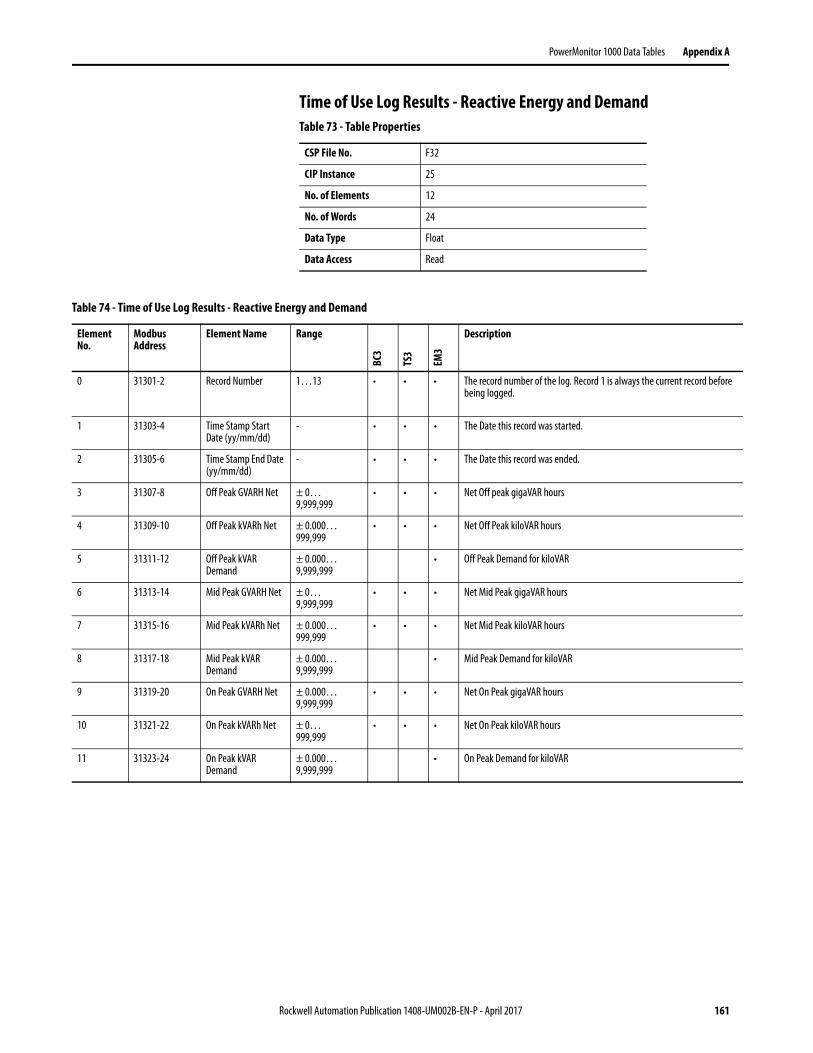
PowerMonitor 1000 Data Tables Appendix A
Time of Use Log Results - Reactive Energy and DemandTable 73 - Table Properties
CSP File No. F32
CIP Instance 25
No. of Elements 12
No. of Words 24
Data Type Float
Data Access Read
Table 74 - Time of Use Log Results - Reactive Energy and Demand
Element No.
Modbus Address
Element Name Range
BC3
TS3
EM3
Description
0 31301-2 Record Number 1…13 • • • The record number of the log. Record 1 is always the current record before being logged.
1 31303-4 Time Stamp Start Date (yy/mm/dd)
- • • • The Date this record was started.
2 31305-6 Time Stamp End Date (yy/mm/dd)
- • • • The Date this record was ended.
3 31307-8 Off Peak GVARH Net ± 0…9,999,999
• • • Net Off peak gigaVAR hours
4 31309-10 Off Peak kVARh Net ± 0.000…999,999
• • • Net Off Peak kiloVAR hours
5 31311-12 Off Peak kVAR Demand
± 0.000…9,999,999
• Off Peak Demand for kiloVAR
6 31313-14 Mid Peak GVARH Net ± 0…9,999,999
• • • Net Mid Peak gigaVAR hours
7 31315-16 Mid Peak kVARh Net ± 0.000…999,999
• • • Net Mid Peak kiloVAR hours
8 31317-18 Mid Peak kVAR Demand
± 0.000…9,999,999
• Mid Peak Demand for kiloVAR
9 31319-20 On Peak GVARH Net ± 0.000…9,999,999
• • • Net On Peak gigaVAR hours
10 31321-22 On Peak kVARh Net ± 0…999,999
• • • Net On Peak kiloVAR hours
11 31323-24 On Peak kVAR Demand
± 0.000…9,999,999
• On Peak Demand for kiloVAR
Rockwell Automation Publication 1408-UM002B-EN-P - April 2017 161
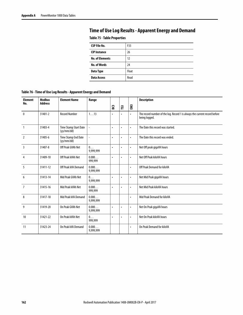
Appendix A PowerMonitor 1000 Data Tables
Time of Use Log Results - Apparent Energy and DemandTable 75 - Table Properties
CSP File No. F33
CIP Instance 26
No. of Elements 12
No. of Words 24
Data Type Float
Data Access Read
Table 76 - Time of Use Log Results - Apparent Energy and Demand
Element No.
Modbus Address
Element Name Range
BC3
TS3
EM3
Description
0 31401-2 Record Number 1…13 • • • The record number of the log. Record 1 is always the current record before being logged.
1 31403-4 Time Stamp Start Date (yy/mm/dd)
- • • • The Date this record was started.
2 31405-6 Time Stamp End Date (yy/mm/dd)
- • • • The Date this record was ended.
3 31407-8 Off Peak GVAh Net 0…9,999,999
• • • Net Off peak gigaVA hours
4 31409-10 Off Peak kVAh Net 0.000…999,999
• • • Net Off Peak kiloVA hours
5 31411-12 Off Peak kVA Demand 0.000…9,999,999
• Off Peak Demand for kiloVA
6 31413-14 Mid Peak GVAh Net 0…9,999,999
• • • Net Mid Peak gigaVA hours
7 31415-16 Mid Peak kVAh Net 0.000…999,999
• • • Net Mid Peak kiloVA hours
8 31417-18 Mid Peak kVA Demand 0.000…9,999,999
• Mid Peak Demand for kiloVA
9 31419-20 On Peak GVAh Net 0.000…9,999,999
• • • Net On Peak gigaVA hours
10 31421-22 On Peak kVAh Net 0…999,999
• • • Net On Peak kiloVA hours
11 31423-24 On Peak kVA Demand 0.000…9,999,999
• On Peak Demand for kiloVA
162 Rockwell Automation Publication 1408-UM002B-EN-P - April 2017
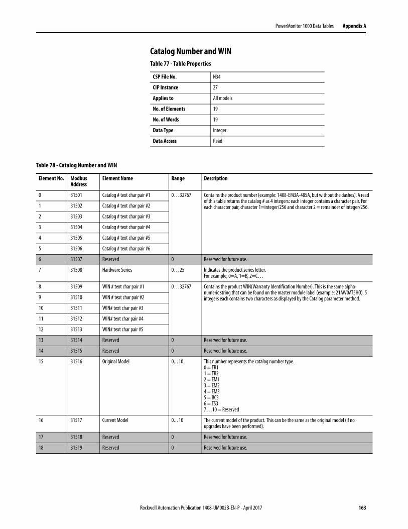
PowerMonitor 1000 Data Tables Appendix A
Catalog Number and WINTable 77 - Table Properties
CSP File No. N34
CIP Instance 27
Applies to All models
No. of Elements 19
No. of Words 19
Data Type Integer
Data Access Read
Table 78 - Catalog Number and WIN
Element No. Modbus Address
Element Name Range Description
0 31501 Catalog # text char pair #1 0…32767 Contains the product number (example: 1408-EM3A-485A, but without the dashes). A read of this table returns the catalog # as 4 integers: each integer contains a character pair. For each character pair, character 1=integer/256 and character 2 = remainder of integer/256.1 31502 Catalog # text char pair #2
2 31503 Catalog # text char pair #3
3 31504 Catalog # text char pair #4
4 31505 Catalog # text char pair #5
5 31506 Catalog # text char pair #6
6 31507 Reserved 0 Reserved for future use.
7 31508 Hardware Series 0…25 Indicates the product series letter.For example, 0=A, 1=B, 2=C…
8 31509 WIN # text char pair #1 0…32767 Contains the product WIN(Warranty Identification Number). This is the same alpha-numeric string that can be found on the master module label (example: 21AW0AT5HO). 5 integers each contains two characters as displayed by the Catalog parameter method.9 31510 WIN # text char pair #2
10 31511 WIN# text char pair #3
11 31512 WIN# text char pair #4
12 31513 WIN# text char pair #5
13 31514 Reserved 0 Reserved for future use.
14 31515 Reserved 0 Reserved for future use.
15 31516 Original Model 0…10 This number represents the catalog number type.0 = TR11 = TR22 = EM13 = EM24 = EM35 = BC36 = TS37…10 = Reserved
16 31517 Current Model 0…10 The current model of the product. This can be the same as the original model (if no upgrades have been performed).
17 31518 Reserved 0 Reserved for future use.
18 31519 Reserved 0 Reserved for future use.
Rockwell Automation Publication 1408-UM002B-EN-P - April 2017 163

Appendix A PowerMonitor 1000 Data Tables
Single-element Password WriteTable 79 - Table Properties
CSP File No. N35
CIP Instance 28
Applies to All models
No. of Elements 1
No. of Words 1
Data Type Integer
Data Access Write
Table 80 - Single-element Password Write
Element No.
Modbus Address
Element Name Range Description
0 40901 Table Password 0…9999 When CIP Explicit Message Security is disabled, a write of this table allows any configuration parameter to be written as a single element or poke. The password stays active for 30 minutes and resets to another 30 minutes when a single element is configured. If CIP Explicit Message Security is enabled, a write to this table is ignored.
164 Rockwell Automation Publication 1408-UM002B-EN-P - April 2017

PowerMonitor 1000 Data Tables Appendix A
User Configurable Table SetupTable 81 - Table Properties
CSP File No. N44
CIP Instance 29
Applies to EM3, TS3 only
No. of Elements 17
No. of Words 17
Data Type Integer
Data Access Read/Write
Table 82 - User Configurable Table Setup
Element No. Modbus Address
Element Name Default Value Range Description
0 41001 Table Password 0 0…9999 When the applicable security (web or explicit message) is disabled, this parameter allows the input data from the source to be accepted. If the applicable security is enabled, this parameter is ignored. Returns -1 on a read.
1 41002 Selection for Parameter #1 29 (L1 Current) 0…110 (EM3)0…78, 87…110 (TS3)
The parameter list can be found in the Parameters for Configurable Table.
2 41003 Selection for Parameter #2 30 (L2 Current)
3 41004 Selection for Parameter #3 31 (L3 Current)
4 41005 Selection for Parameter #4 37 (L1-L2 Voltage)
5 41006 Selection for Parameter #5 38 (L2-L3 Voltage)
6 41007 Selection for Parameter #6 39 (L3-L1 Voltage)
7 41008 Selection for Parameter #7 41 (Frequency)
8 41009 Selection for Parameter #8 52 (Total Real Power)
9 41010 Selection for Parameter #9 56 (Total Reactive Power)
10 41011 Selection for Parameter #10 60 (Total Apparent Power)
11 41012 Selection for Parameter #11 48 (3 Phase True Power Factor)
12 41013 Selection for Parameter #12 70 (Real Energy Net (kWh))
13 41014 Selection for Parameter #13 62 (Status 1 Count x1)
14 41015 Selection for Parameter #14 64 (Status 2 Count x1)
15 41016 Selection for Parameter #15 79 (Real Power Demand)
16 41017 Selection for Parameter #16 8 (Status Input States)
Rockwell Automation Publication 1408-UM002B-EN-P - April 2017 165

Appendix A PowerMonitor 1000 Data Tables
Table 83 - Parameters for Configurable Table
Parameter No. Parameter Name Description TS3 EM3
0 None No Parameter. • •
1 Date: Year Refer to Date and Time Configuration table. • •
2 Date: Month • •
3 Date: Day • •
4 Time: Hour • •
5 Time: Minute • •
6 Time: Seconds • •
7 Time: Hundredths • •
8 Status Input States Refer to Discrete Results table. • •
9 Output Word • •
10 Wiring Status Refer to Wiring Diagnostics Results table. • •
11 Voltage Input Missing • •
12 Voltage Input Inverted • •
13 Current Input Missing • •
14 Current Input Inverted • •
15 Voltage Rotation • •
16 Current Rotation • •
17 Voltage Phase 1 Angle • •
18 Voltage Phase 1 Magnitude • •
19 Voltage Phase 2 Angle • •
20 Voltage Phase 2 Magnitude • •
21 Voltage Phase 3 Angle • •
22 Voltage Phase 3 Magnitude • •
23 Current Phase 1 Angle • •
24 Current Phase 1 Magnitude • •
25 Current Phase 2 Angle • •
26 Current Phase 2 Magnitude • •
27 Current Phase 3 Angle • •
28 Current Phase 3 Magnitude • •
29 L1 Current Refer to Volts Amps Frequency Results table. • •
30 L2 Current • •
31 L3 Current • •
32 Average Current • •
33 L1-N Volts • •
166 Rockwell Automation Publication 1408-UM002B-EN-P - April 2017

PowerMonitor 1000 Data Tables Appendix A
34 L2-N Volts Refer to Volts Amps Frequency Results table. • •
35 L3-N Volts • •
36 Average L-N Volts • •
37 L1-L2 Volts • •
38 L2-L3 Volts • •
39 L3-L1 Volts • •
40 Average L-L Volts • •
41 Frequency • •
42 Percent Current Unbalance • •
43 Percent Voltage Unbalance • •
44 Metering Iteration • •
45 L1 True Power Factor Refer to Power Results table. • •
46 L2 True Power Factor • •
47 L3 True Power Factor • •
48 3 Phase True Power Factor • •
49 L1 kW • •
50 L2 kW • •
51 L3 kW • •
52 Total kW • •
53 L1 kVAR • •
54 L2 kVAR • •
55 L3 kVAR • •
56 Total kVAR • •
57 L1 kVA • •
58 L2 kVA • •
59 L3 kVA • •
60 Total kVA • •
61 Status 1 Count xM Refer to Energy Results table. • •
62 Status 1 Count x1 • •
63 Status 2 Count xM • •
64 Status 2 Count x1 • •
65 GWh Fwd • •
66 kWh Fwd • •
67 GWh Rev. • •
68 kWh Rev. • •
69 GWh Net • •
70 kWh Net Refer to Energy Results table. • •
71 GVARH Fwd • •
72 kVARh Fwd • •
73 GVARH Rev. • •
74 kVARh Rev. • •
75 GVARH Net • •
76 kVARh Net • •
77 GVAh Net • •
78 kVAh Net • •
Table 83 - Parameters for Configurable Table
Parameter No. Parameter Name Description TS3 EM3
Rockwell Automation Publication 1408-UM002B-EN-P - April 2017 167

Appendix A PowerMonitor 1000 Data Tables
79 kW Demand Refer to Demand Results table. •
80 kVAR Demand •
81 kVA Demand •
82 Demand PF •
83 Projected kW Demand •
84 Projected kVAR Demand •
85 Projected kVA Demand •
86 Elapsed Demand Period Time
•
87 Bulletin Number Refer to Unit Run Status Results table. • •
88 Series Letter • •
89 Catalog Device Type • •
90 Communication Type • •
91 Application FRN • •
92 Boot Code FRN • •
93 Default Device ID • •
94 Accuracy Class • •
95 Overall Status • •
96 Flash Memory • •
97 SRAM • •
98 NVRAM • •
99 SPI Interface • •
100 Real Time Clock • •
101 Watchdog Timer • •
102 Metering • •
103 LCD Interface • •
104 Serial Communications • •
105 Ethernet Communications • •
106 Input Over Range Refer to Unit Run Status Results table. • •
107 Phase Loss Detection • •
108 Terminal Locked • •
109 Single Element Password Accepted
• •
110 Error Recorded • •
Table 83 - Parameters for Configurable Table
Parameter No. Parameter Name Description TS3 EM3
168 Rockwell Automation Publication 1408-UM002B-EN-P - April 2017

PowerMonitor 1000 Data Tables Appendix A
Security Policy Configuration TableTable 84 - Table Properties
CSP File No. N45
CIP Instance 30
Applies to All models
No. of Elements 15
No. of Words 15
Data Type Integer
Data Access Read/Write
Table 85 - Security Policy Configuration Table
Element No.
Modbus Address
Element Name Default Value
Range Description
0 41101 Table Password 0 0…9999 Required for configuration, returns -1. When the applicable security (web or explicit message) is disabled, this parameter allows the input data from the source to be accepted. If the applicable security is enabled, this parameter is ignored. Returns -1 on a read.
1 41102 Hardware Configuration Lock 0 0…1 0 = Lock Analog Input configuration, energy configuration parameters, security policy configuration and command word 1 parameters including unit reset. 1 = Lock Analog Input configuration, energy configuration parameters, security policy configuration and command word 1 parameters including unit reset, lock Ethernet configuration.
2 41103 Communication Port Disable 0 0…2 0 = No physical ports disabled.1 = Ethernet port disable. 2 = RS485 port disable.
3 41104 Web Page Disable 0 0…1 0 = Enable web page access. 1 = Disable web page access.
4 41105 FTP Port Disable 0 0…1 0 = Enable ftp port access. 1 = Disable ftp port access.
5 41106 Flash Update Disable Configuration Lock
0 0…1 0 = Allow firmware flash update when configuration is locked by hardware.1 = Disable firmware flash update when configuration is locked by hardware.
6 41107 Flash Update Disable Security Active 0 0…3 0 = Allow firmware flash update when security is enabled. 1 = Disable firmware flash update when security for CIP is enabled. 2 = Disable firmware flash update when security for web page is enabled.IMPORTANT: Under setting 2, the CIP Reset Service is active and can still be used to reset the PowerMonitor 1000 unit. Enable security for CIP to block CIP Reset Service Messages.3 = Disable firmware flash update when security for CIP or web page is enabled.IMPORTANT: If Security is enabled and the Admin Login source IP address and the Flash Source IP address are the same, then Flash Update is allowed.
Rockwell Automation Publication 1408-UM002B-EN-P - April 2017 169

Appendix A PowerMonitor 1000 Data Tables
7 41108 HTTPS Enable 0 0…1 0 = HTTPS disable. 1 = HTTPS enable.
8 41109 FTPS Enable 0 0…1 0 = FTPS disable. 1 = FTPS enable.
9 41110 Reserved 0 0 Reserved for future use.
10 41111 Reserved 0 0 Reserved for future use.
11 41112 Reserved 0 0 Reserved for future use.
12 41113 Reserved 0 0 Reserved for future use.
13 41114 Reserved 0 0 Reserved for future use.
14 41115 Reserved 0 0 Reserved for future use.
Table 85 - Security Policy Configuration Table
Element No.
Modbus Address
Element Name Default Value
Range Description
170 Rockwell Automation Publication 1408-UM002B-EN-P - April 2017
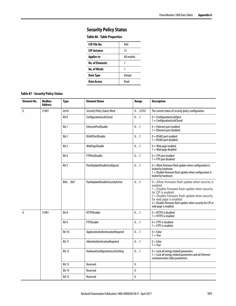
PowerMonitor 1000 Data Tables Appendix A
Security Policy StatusTable 86 - Table Properties
CSP File No. N46
CIP Instance 31
Applies to All models
No. of Elements 1
No. of Words 1
Data Type Integer
Data Access Read
Table 87 - Security Policy Status
Element No. Modbus Address
Type Element Name Range Description
0 31901 Int16 Security Policy Status Word 0…32767 The current status of security policy configuration.
Bit 0 ConfigurationLockClosed 0…1 0 = ConfigurationLockOpen 1 = ConfigurationLockClosed
Bit 1 EthernetPortDisable 0…1 0 = Ethernet port enabled 1 = Ethernet port disabled
Bit 2 RS485PortDisable 0…1 0 = RS485 port enabled 1 = RS485 port disabled
Bit 3 WebPageDisable 0…1 0 = Web page enabled 1 = Web page disabled
Bit 4 FTPPortDisable 0…1 0 = FTP port enabled 1 = FTP port disabled
Bit 5 FlashUpdateDisableConfigLock 0…1 0 = Allow firmware flash update when configuration is locked by hardware. 1 = Disable firmware flash update when configuration is locked by hardware.
Bit6…Bit7 FlashUpdateDisableSecurityActive 0…3 0 = Allow firmware flash update when security is enabled. 1 = Disable firmware flash update when security for CIP is enabled. 2 = Disable firmware flash update when security for web page is enabled. 3 = Disable firmware flash update when security for CIP or web page is enabled.
0 31901 Bit 8 HTTPSEnable 0…1 0 = HTTPS is disabled 1 = HTTPS is enabled
Bit 9 FTPSEnable 0…1 0 = FTPS is disabled 1 = FTPS is enabled.
Bit 10 ApplicationAuthenticationRequired 0…1 0 = False 1 = True
Bit 11 AdminAuthenticationRequired 0…1 0 = False 1 = True
Bit 12 HardwareConfigurationLockSetting 0…1 0 = Lock all energy related parameters1 = Lock all energy related parameters and all Ethernet communication table parameters.
Bit 13 Reserved 0
Bit 14 Reserved 0
Bit 15 Reserved 0
Rockwell Automation Publication 1408-UM002B-EN-P - April 2017 171
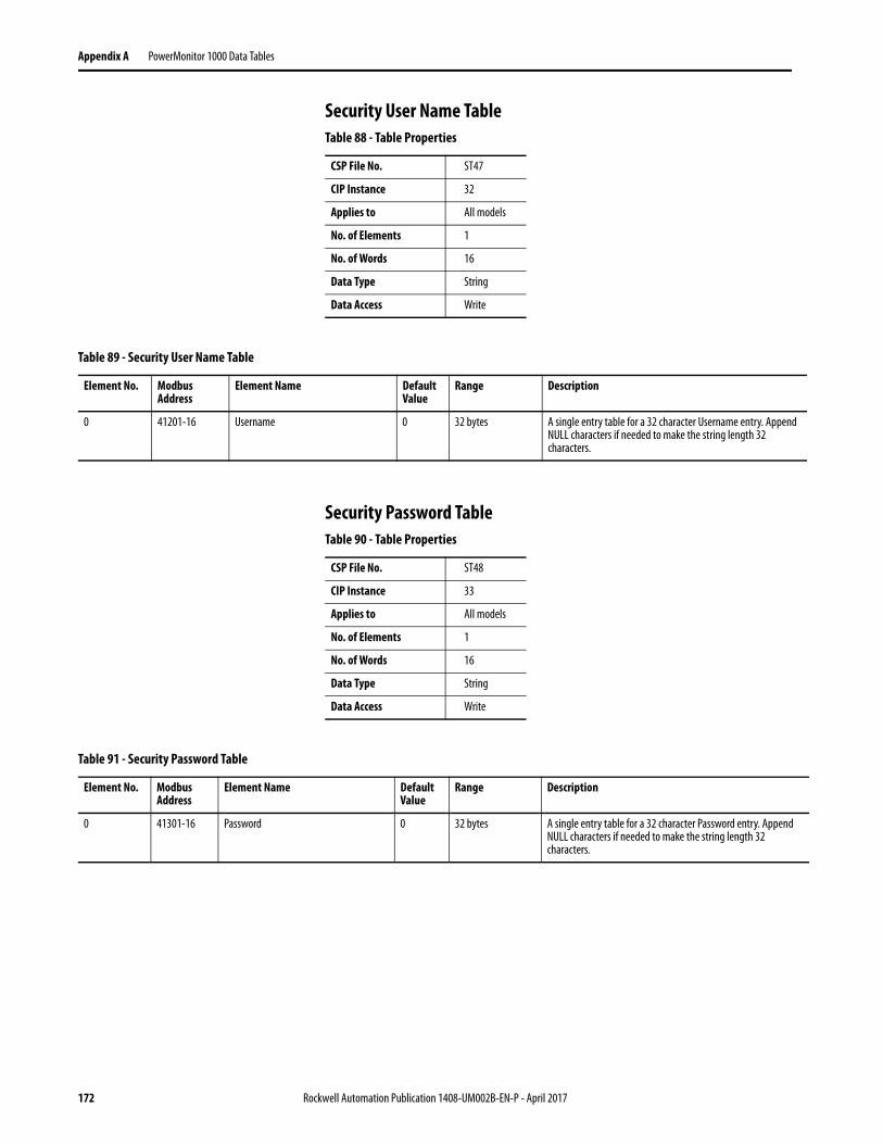
Appendix A PowerMonitor 1000 Data Tables
Security User Name Table
Security Password Table
Table 88 - Table Properties
CSP File No. ST47
CIP Instance 32
Applies to All models
No. of Elements 1
No. of Words 16
Data Type String
Data Access Write
Table 89 - Security User Name Table
Element No. Modbus Address
Element Name Default Value
Range Description
0 41201-16 Username 0 32 bytes A single entry table for a 32 character Username entry. Append NULL characters if needed to make the string length 32 characters.
Table 90 - Table Properties
CSP File No. ST48
CIP Instance 33
Applies to All models
No. of Elements 1
No. of Words 16
Data Type String
Data Access Write
Table 91 - Security Password Table
Element No. Modbus Address
Element Name Default Value
Range Description
0 41301-16 Password 0 32 bytes A single entry table for a 32 character Password entry. Append NULL characters if needed to make the string length 32 characters.
172 Rockwell Automation Publication 1408-UM002B-EN-P - April 2017

PowerMonitor 1000 Data Tables Appendix A
Alarm Status ResultsTable 92 - Table Properties
CSP File No. N49
CIP Instance 34
Applies to EM3 only
No. of Elements 9
No. of Words 9
Data Type Integer
Data Access Read
Table 93 - Alarm Status Results
Element No.
Modbus Address
Element Name Range Description
0 31701 Input Over Range 0…3 0 indicates normal operation. Bit 0 = Voltage Input over range Bit 1 = Current Input over range
1 31702 Phase Loss Detection 0…7 0 Indicates normal running condition. Bit 0 = Loss of phase A Bit 1 = Loss of phase B Bit 2 = Loss of phase C
2 31703 Terminal Locked 0…1 Reports 1 if terminal is locked.
3 31704 KYZ Output Forced 0…3 Indicates Relay/KYZ Output is Forced (1) or Not Forced (0); Forced On (1) or Forced Off (0). Bit 0 = Forced/Not Forced Bit 1 = Forced On/Forced off
4 31705 Status Input 0…3 Indicates status input activated (1) or deactivated (0) Bit 0 = Input 1 Bit 1 = Input 2
5 31706 Energy Register Rollover 0…31 Indicate which energy registers rollover Bit 0 = Wh Register Bit 1 = VARh Register Bit 2 = VAh Register Bit 3 = Status input 1 counter Bit 4 = Status input 2 counter
6 31707 Missed External Demand Sync 0…1 When External Demand Sync is missed, set to 1; when external Demand Sync is met, reset to 0.
7 31708 Reserved 0 Reserved for future use
8 31709 Reserved 0 Reserved for future use
Rockwell Automation Publication 1408-UM002B-EN-P - April 2017 173

Appendix A PowerMonitor 1000 Data Tables
Alarm Log ResultsTable 94 - Table Properties
CSP File No. N50
CIP Instance 35
Applies to EM3 only
No. of Elements 8
No. of Words 8
Data Type Integer
Data Access Read
Table 95 - Alarm Log Results
Element No. Modbus Address
Element Name Range Description
0 31801 Status Record Internal Identifier 1…50 Used to verify record sequence when returning multiple records.
1 31802 Timestamp Year of record - The year when the record was recorded.
2 31803 Timestamp Month/Day - The month and day when the record was recorded.
3 31804 Timestamp Hour/Minute - The hour and minute when the record was recorded.
4 31805 Timestamp Seconds/Hundredths - The seconds and hundredths when the record was recorded.
5 31806 Status Event Type 0…512 Indicates the type of alarm event that has occurred.
6 31807 General Code 0…4096 Indicates general information about the alarm event.
7 31808 Information Code 0…256 Indicates specific information about the alarm event.
174 Rockwell Automation Publication 1408-UM002B-EN-P - April 2017
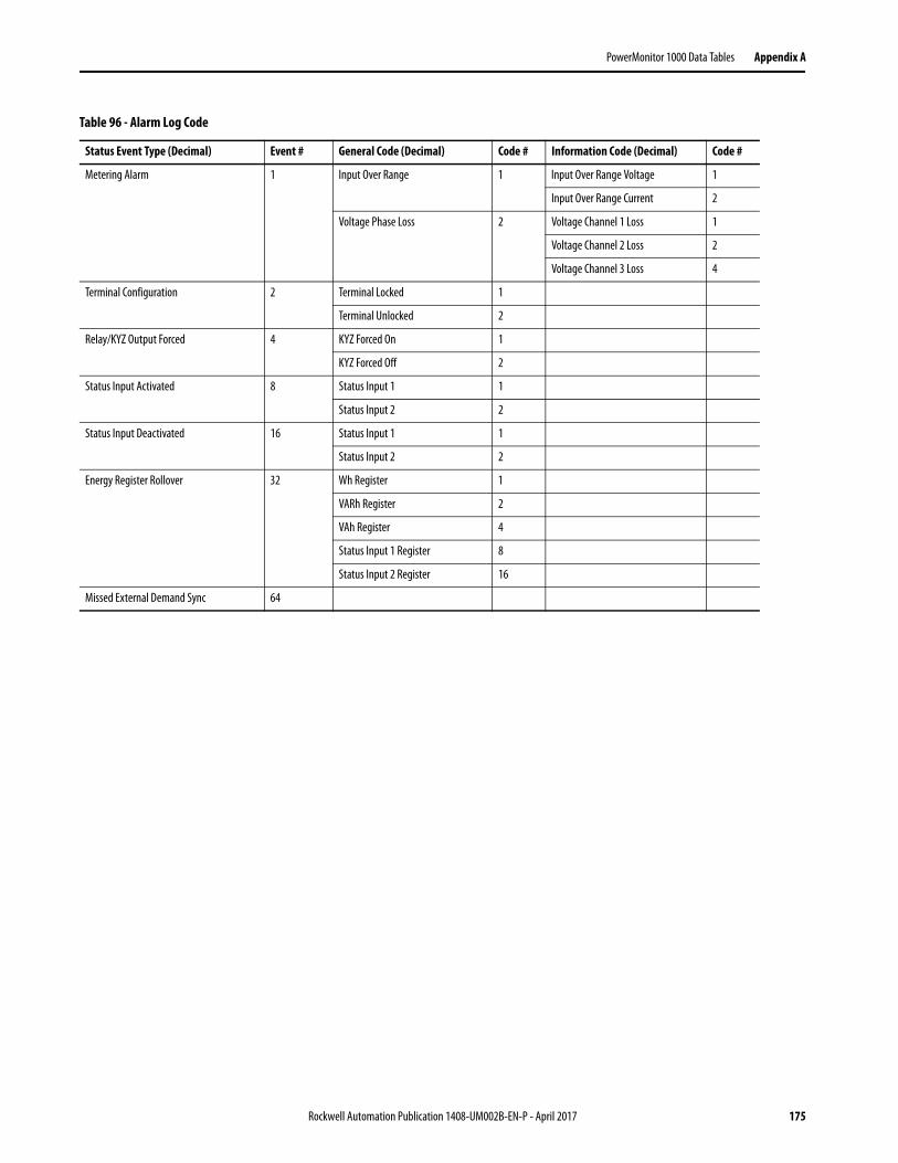
PowerMonitor 1000 Data Tables Appendix A
Table 96 - Alarm Log Code
Status Event Type (Decimal) Event # General Code (Decimal) Code # Information Code (Decimal) Code #
Metering Alarm 1 Input Over Range 1 Input Over Range Voltage 1
Input Over Range Current 2
Voltage Phase Loss 2 Voltage Channel 1 Loss 1
Voltage Channel 2 Loss 2
Voltage Channel 3 Loss 4
Terminal Configuration 2 Terminal Locked 1
Terminal Unlocked 2
Relay/KYZ Output Forced 4 KYZ Forced On 1
KYZ Forced Off 2
Status Input Activated 8 Status Input 1 1
Status Input 2 2
Status Input Deactivated 16 Status Input 1 1
Status Input 2 2
Energy Register Rollover 32 Wh Register 1
VARh Register 2
VAh Register 4
Status Input 1 Register 8
Status Input 2 Register 16
Missed External Demand Sync 64
Rockwell Automation Publication 1408-UM002B-EN-P - April 2017 175

Appendix A PowerMonitor 1000 Data Tables
TIP This is not truly a data table, but a reply to a PCCC diagnostic status request (used by RSWho to display text and an icon for the power monitor). This data is not accessible by using Modbus communication.
Table 97 - DF1 PCCC Diagnostic Status Reply
Byte Contents Description
1 Mode/status Unused
2 Type extender EE
3 Extended interface type 34h = DF1 Full Duplex 36h = DF1 Half Duplex Slave 65h = Ethernet
4 Extended processor type 95h = CIP Aware
5 Vendor ID (low byte) 1
6 Vendor ID (high byte) 0
7 Product Type (low byte) 73h
8 Product Type (high byte) 0
9 Product Code (low byte) B1h
10 Product Code (high byte) 0
11 Major Revision Beginning from 1
12 Minor Revision Beginning from 1
13 Status (low byte) 74h
14 Status (high byte) 0
15 Serial Number (lowest byte) Unique 4 bytes assigned code
16 Serial Number
17 Serial Number
18 Serial Number (highest byte)
19 Product Name length Product name is expected up to 32 characters
20 Product Name (1st character) The actual length of the table is depending on the product name length. The byte size of this table is at most 51.21 Product Name (2nd character)
22 Product Name (3rd character)
23 Product Name (4th character)
24 Product Name (5th character)
25 Product Name (6th character)
26 Product Name (7th character)
27 Product Name (8th character)
… …
51 Product Name (last character)
176 Rockwell Automation Publication 1408-UM002B-EN-P - April 2017
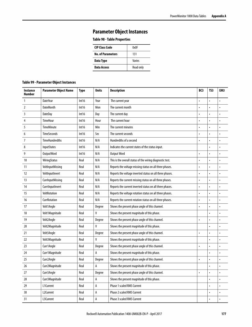
PowerMonitor 1000 Data Tables Appendix A
Parameter Object InstancesTable 98 - Table Properties
CIP Class Code 0x0F
No. of Parameters 131
Data Type Varies
Data Access Read only
Table 99 - Parameter Object Instances
Instance Number
Parameter Object Name Type Units Description BC3 TS3 EM3
1 DateYear Int16 Year The current year • • •
2 DateMonth Int16 Mon The current month • • •
3 DateDay Int16 Day The current day • • •
4 TimeHour Int16 Hour The current hour • • •
5 TimeMinute Int16 Min The current minutes • • •
6 TimeSeconds Int16 Sec The current seconds • • •
7 TimeHundredths Int16 N/A Hundredths of a second • • •
8 InputStates Int16 N/A Indicates the current states of the status input. • •
9 OutputWord Int16 N/A Output Word • • •
10 WiringStatus Real N/A This is the overall status of the wiring diagnostic test. • • •
11 VoltInputMissing Real N/A Reports the voltage missing status on all three phases. • • •
12 VoltInputInvert Real N/A Reports the voltage inverted status on all three phases. • • •
13 CurrInputMissing Real N/A Reports the current missing status on all three phases. • • •
14 CurrtInputInvert Real N/A Reports the current inverted status on all three phases. • • •
15 VoltRotation Real N/A Reports the voltage rotation status on all three phases. • • •
16 CurrRotation Real N/A Reports the current rotation status on all three phases. • • •
17 Volt1Angle Real Degree Shows the present phase angle of this channel. • • •
18 Volt1Magnitude Real V Shows the present magnitude of this phase. • •
19 Volt2Angle Real Degree Shows the present phase angle of this channel. • • •
20 Volt2Magnitude Real V Shows the present magnitude of this phase. • •
21 Volt3Angle Real Degree Shows the present phase angle of this channel. • • •
22 Volt3Magnitude Real V Shows the present magnitude of this phase. • •
23 Curr1Angle Real Degree Shows the present phase angle of this channel. • • •
24 Curr1Magnitude Real A Shows the present magnitude of this phase. • •
25 Curr2Angle Real Degree Shows the present phase angle of this channel. • • •
26 Curr2Magnitude Real A Shows the present magnitude of this phase. • •
27 Curr3Angle Real Degree Shows the present phase angle of this channel. • • •
28 Curr3Magnitude Real A Shows the present magnitude of this phase. • •
29 L1Current Real A Phase 1 scaled RMS Current • •
30 L2Current Real A Phase 2 scaled RMS Current • •
31 L3Current Real A Phase 3 scaled RMS Current • •
Rockwell Automation Publication 1408-UM002B-EN-P - April 2017 177

Appendix A PowerMonitor 1000 Data Tables
32 AverageCurrent Real A Average RMS Current • •
33 L1NVolts Real V Phase 1 scaled RMS Voltage • •
34 L2NVolts Real V Phase 2 scaled RMS Voltage • •
35 L3NVolts Real V Phase 3 scaled RMS Voltage • •
36 AverageLNVolts Real V Averaged RMS Voltage • •
37 L1L2Volts Real V Line 1 to Line 2 Volts • •
38 L2L3Volts Real V Line 2 to Line 3 Volts • •
39 L3L1Volts Real V Line 3 to Line 1 Volts • •
40 AverageLLVolts Real V Average Line to Line Volts • •
41 Frequency Real Hz Last frequency reading. • •
42 CurrUnbalance Real % Percent maximum deviation from Ave. • •
43 VoltUnbalance Real % Percent maximum deviation from Ave. • •
44 MeterIteration Real N/A Increments by 1 for each new metering calculation. • • •
45 L1TruePF Real % Percent ratio between power and apparent power L1. • • •
46 L2TruePF Real % Percent ratio between power and apparent power L2. • • •
47 L3TruePF Real % Percent ratio between power and apparent power L3. • • •
48 3PhaseTruePF Real % Percent ratio between total power and total apparent power. • • •
49 L1kW Real kW Line 1 kW • • •
50 L2kW Real kW Line 2 kW • • •
51 L3kW Real kW Line 3 kW • • •
52 TotalkW Real kW Total kW • • •
53 L1kVAR Real kVAR Line 1 kVAR • • •
54 L2kVAR Real kVAR Line 2 kVAR • • •
55 L3kVAR Real kVAR Line 3 kVAR • • •
56 TotalkVAR Real kVAR Total kVAR • • •
57 L1kVA Real kVA Line 1 kVA • • •
58 L2kVA Real kVA Line 2 kVA • • •
59 L3kVA Real kVA Line 3 kVA • • •
60 TotalkVA Real kVA Total kVA • • •
61 Status1CountxM Real N/A Status 1 count times 1,000,000 • •
62 Status1Countx1 Real N/A Status 1 count times 1 • •
63 Status2CountxM Real N/A Status 2 count times 1,000,000 • •
64 Status2Countx1 Real N/A Status 2 count times 1 • •
65 GWhFwd Real GWh Forward gigawatt hours • • •
66 kWhFwd Real kWh Forward kilowatt hours • • •
67 GWhRev Real GWh Reverse gigawatt hours • • •
68 kWhRev Real kWh Reverse kilowatt hours • • •
69 GWhNet Real GWh Net gigawatt hours • • •
70 kWhNet Real kWh Net kilowatt hours • • •
Table 99 - Parameter Object Instances
Instance Number
Parameter Object Name Type Units Description BC3 TS3 EM3
178 Rockwell Automation Publication 1408-UM002B-EN-P - April 2017

PowerMonitor 1000 Data Tables Appendix A
71 GVARhFwd Real GVARh Forward gigaVAR hours • • •
72 kVARhFwd Real kVARh Forward kiloVAR hours • • •
73 GVARhRev Real GVARh Reverse gigaVAR hours • • •
74 kVARhRev Real kVARh Reverse kiloVAR hours • • •
75 GVARhNet Real GVARh Net gigaVAR hours • • •
76 kVARhNet Real kVARh Net kiloVAR hours • • •
77 GVAhNet Real GVAh Net gigaVA hours • • •
78 kVAhNet Real kVAh Net kiloVA hours • • •
79 kWDemand Real kW The average real power during the last demand period. •
80 kVARDemand Real kVAR The average reactive power during the last demand period. •
81 kVADemand Real kVA The average apparent power during the last demand period. •
82 DemandPF Real % The average demand for PF during the last demand period. •
83 ProjkWDemand Real kW The projected total real power for the current period. •
84 ProjkVARDemand Real kVAR The projected total reactive power for the current period. •
85 ProjkVADemand Real kVA The projected total apparent power for the current period. •
86 ElapsedTime Real N/A The amount of time that has elapsed during the current period. •
87 BulletinNum Int16 N/A The bulletin number of product. • • •
88 SeriesLetter Int16 N/A Indicates the unit hardware series letter. • • •
89 CatalogNum Int16 N/A The catalog number type of this device. • • •
90 CommType Int16 N/A The communication type of this device. • • •
91 AppFRN Int16 N/A The current firmware revision. • • •
92 BootFRN Int16 N/A The current boot code revision. • • •
93 DeviceID Int16 N/A A semi-unique number assigned to a device at the time it is manufactured. • • •
94 AccuracyClass Int16 N/A Indicates the revenue metering accuracy class of the PowerMonitor 1000 as it is shipped from the factory.
• • •
95 OverallStatus Int16 N/A 0 indicates normal operation. Each bit indicates a different fault condition. • • •
96 FlashMemStatus Int16 N/A Report Flash status. • • •
97 SRAMStatus Int16 N/A Report SRAM status. • • •
98 NVRAMStatus Int16 N/A Report NVRAM status. • • •
99 SPIStatus Int16 N/A Report SPI Interface status. • • •
100 RTCStatus Int16 N/A Report Real Time Clock status. • • •
101 WDTimerStatus Int16 N/A Report watchdog time out. • • •
102 MeteringStatus Int16 N/A Report metering status. • • •
103 LCDStatus Int16 N/A Report LCD interface status. • •
104 SerialCommStatus Int16 N/A Report serial communications status. • • •
105 ENTCommStatus Int16 N/A Report ethernet communications status. • • •
106 InputOverRange Int16 N/A Indicates voltage and current over range status. • • •
107 PhaseLossDetect Int16 N/A Indicates phase loss status. • • •
108 TerminalLocked Int16 N/A Reports 1 if terminal is locked. • • •
Table 99 - Parameter Object Instances
Instance Number
Parameter Object Name Type Units Description BC3 TS3 EM3
Rockwell Automation Publication 1408-UM002B-EN-P - April 2017 179
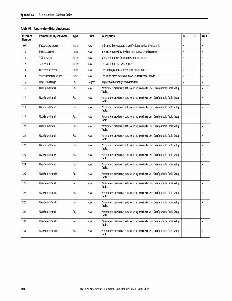
Appendix A PowerMonitor 1000 Data Tables
109 PasswordAccepted Int16 N/A Indicates the password is verified and active if value is 1. • • •
110 ErrorRecorded Int16 N/A It is incremented by 1 when an internal error happens • • •
111 TSTimesLeft Int16 N/A Remaining times for troubleshooting mode • • •
112 TableNum Int16 N/A The last table that was written. • • •
113 OffendingElement Int16 N/A The first rejected element in the table write. • • •
114 WriteErrorStatusWord Int16 N/A The write error status word when a write was made. • • •
115 DegOutofRange Real Degree Degrees out of range was detected. • • •
116 UserSelectPara1 Real N/A Parameters previously setup during a write to User Configurable Table Setup Table.
• •
117 UserSelectPara2 Real N/A Parameters previously setup during a write to User Configurable Table Setup Table.
• •
118 UserSelectPara3 Real N/A Parameters previously setup during a write to User Configurable Table Setup Table.
• •
119 UserSelectPara4 Real N/A Parameters previously setup during a write to User Configurable Table Setup Table.
• •
120 UserSelectPara5 Real N/A Parameters previously setup during a write to User Configurable Table Setup Table.
• •
121 UserSelectPara6 Real N/A Parameters previously setup during a write to User Configurable Table Setup Table.
• •
122 UserSelectPara7 Real N/A Parameters previously setup during a write to User Configurable Table Setup Table.
• •
123 UserSelectPara8 Real N/A Parameters previously setup during a write to User Configurable Table Setup Table.
• •
124 UserSelectPara9 Real N/A Parameters previously setup during a write to User Configurable Table Setup Table.
• •
125 UserSelectPara10 Real N/A Parameters previously setup during a write to User Configurable Table Setup Table.
• •
126 UserSelectPara11 Real N/A Parameters previously setup during a write to User Configurable Table Setup Table.
• •
127 UserSelectPara12 Real N/A Parameters previously setup during a write to User Configurable Table Setup Table.
• •
128 UserSelectPara13 Real N/A Parameters previously setup during a write to User Configurable Table Setup Table.
• •
129 UserSelectPara14 Real N/A Parameters previously setup during a write to User Configurable Table Setup Table.
• •
130 UserSelectPara15 Real N/A Parameters previously setup during a write to User Configurable Table Setup Table.
• •
131 UserSelectPara16 Real N/A Parameters previously setup during a write to User Configurable Table Setup Table.
• •
Table 99 - Parameter Object Instances
Instance Number
Parameter Object Name Type Units Description BC3 TS3 EM3
180 Rockwell Automation Publication 1408-UM002B-EN-P - April 2017

Appendix B
Specifications
Technical Specifications Table 100 - Technical Specifications - 1408-BC3A-xxx, 1408-TS3A-xxx, 1408-EM3A-xxx
Attribute Accuracy in % of Reading at 25 °C (77 °F) 50/60 Hz Unity Power Factor
Nominal / Range
Applies to
BC3 TS3 EM3
Voltage sense inputs: V1, V2, V3
±0.5% X X Line-neutral rms:347V / 15…399V Line-line rms:600V / 26…691V
Current sense input: I1, I2, I3
±0.5% X X 5A / 0.05…10.0A rms
Frequency ±0.05 Hz X X 50 or 60 Hz /40…75 Hz
Power functions: kW, kVA, kVAR
EN62053-21:2003 Accuracy Requirement Class 1(1)
(1) Fast transient external influence tested at 2 kV.
X X X
Demand functions: kW, kVA, kVAR
X
Energy functions: kWH, kVAH, kVARH
X X X
Metering update rates
100 mS V, I, Hz200 mS Power
X X X
Rockwell Automation Publication 1408-UM002B-EN-P - April 2017 183

Appendix B Specifications
Table 101 - Input and Output Specifications - 1408-BC3A-xxx, 1408-TS3A-xxx, 1408-EM3A-xxx
Attribute Value
Control power 85…264V AC 47…63 Hz 125…250V DC4 VA max
Voltage sense inputs: V1, V2, V3
Input impedance: 5 M Ω minInput current: 2 mA max
Current sense inputs: I1, I2, I3 Overload withstand: 15 A continuous, 200 A for 1/2 sBurden: 0.05V AImpedance: 0.002 ΩMax crest factor at 5 A is 3.0Starting current: 5 mA
Status inputs Contact closure (internal 24V DC) (except BC3)
KYZ output 80 mA at 240V AC / 300V DC (except BC3)
Table 102 - Environmental Specifications - 1408-BC3A-xxx, 1408-TS3A-xxx, 1408-EM3A-xxx
Attribute Value
Dielectric withstand UL61010, EN61010Pollution Degree 2
Terminal blocks 0.34…2.5 mm2 (22…14 AWG), 75 °C (167 °F) min copper wire onlyRecommended torque 0.8 N·m (7 lb·in)
Operating temperature
-10…60 °C (14…140 °F)
Storage temperature
-40…85 °C (-40…185 °F)
Humidity 5…95%, noncondensing
Vibration 2.0 g 10…500 Hz
Shock 30 g peak each axis (operating)50 g peak each axis (nonoperating)
184 Rockwell Automation Publication 1408-UM002B-EN-P - April 2017

Appendix C
Certifications
The power monitor adheres to these certifications.
EtherNet/IP Network Conformance Testing
All power monitor products equipped with an EtherNet/IP network communication port bear the mark shown. This mark indicates the power monitor has been tested at an Open Device Vendor Association (ODVA) independent test lab and has passed the EtherNet/IP network conformance test. This test provides a level of assurance that the power monitor interoperates with other conformance tested EtherNet/IP network devices (including devices from other vendors). One representative device from the power monitor EtherNet/IP network family of devices; the 1408-EM3-ENT has been tested by ODVA using EtherNet/IP Conformance Test, version A2.8. The ODVA website http://www.odva.org maintains a list of products that have passed the conformance test at one of their test labs.
UL/CU-L UL 508 listed, File E56639, for Industrial Control Equipment and C-UL Certified.
CE Certification If this product bears the CE marking, it is approved for installation within the European Union and EEA regions. It has been designed to meet the following directives.
EMC Directive
This product is tested to meet Council Directive 2004/108/EC Electromagnetic Compatibility (EMC) and the following standards, in whole, documented in a technical construction file.
EN55011 – Radiated Electromagnetic Emissions
EN55011 – Conducted Emissions
EN 61326-1 Electrical Equipment for Measurement - EMC Requirements
EN61000 – Immunity
Rockwell Automation Publication 1408-UM002B-EN-P - April 2017 185

Appendix C Certifications
This product is intended for use in an industrial environment.
Low Voltage Directive
This product is tested to meet Council Directive 2006/95/EC Low Voltage, by applying the safety requirements of EN61010-1 and EN 61010-2-030.
This equipment is classified as open equipment and must be installed (mounted) in an enclosure during operation as a means of providing safety protection.
International Standard IEC 529 / NEMA / UL 508 Degree of Protection
The Bulletin 1408 PowerMonitor 1000 unit is rated as IP10 degree of protection per International Standard IEC 529. It is considered an open device per NEMA and UL 508.
Follow the recommended installation guidelines to maintain these ratings.
ANSI/IEEE Tested
Meets or exceeds the Surge Withstand Capability (SWC) C37.90.1 - 2002 for protective relays and relay systems on all power-connection circuit terminations.
WARNING: This product is a Class A (industrial) product. In a Class B (residential or commercial) environment, this product can cause radio interference in which case the installer can be required to take extra measures to mitigate the interference.
186 Rockwell Automation Publication 1408-UM002B-EN-P - April 2017

Appendix D
Additional EtherNet/IP Information
Common Industrial Protocol (CIP) Objects
The PowerMonitor 1000 unit EtherNet/IP Communication Module supports the following Common Industrial Protocol (CIP).
Identity Object - CLASS CODE 0x0001
The following three instances of the Identity Object are supported.
The following class attributes are supported for the Identity Object.
Table 103 - CIP Object Classes
Class Object
0x0001 Identity
0x0002 Message Router
0x0004 Assembly
0x004E Base Energy Object
0x004F Electrical Energy Object
0x00F5 TCP/IP Interface Object
0x00F6 Ethernet Link Object
0x000F Parameter Object
0x0037 File Object
Table 104 - Identity Object Instances
Instance Name Revision Attribute
1 Image File The firmware image
2 Boot Loader The firmware Boot Loader
3 Upgrade File The firmware Upgrade File
Table 105 - Identity Object Class Attributes
Attribute ID Access Rule Name Data Type Value
1 Get Revision UINT 1
2 Get Max Instance UINT 3
Rockwell Automation Publication 1408-UM002B-EN-P - April 2017 187
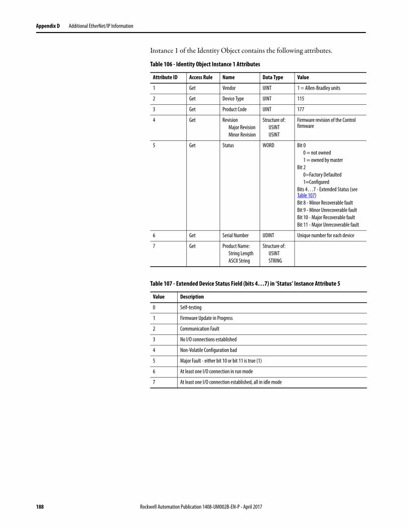
Appendix D Additional EtherNet/IP Information
Instance 1 of the Identity Object contains the following attributes.
Table 106 - Identity Object Instance 1 Attributes
Attribute ID Access Rule Name Data Type Value
1 Get Vendor UINT 1 = Allen-Bradley units
2 Get Device Type UINT 115
3 Get Product Code UINT 177
4 Get RevisionMajor RevisionMinor Revision
Structure of:USINTUSINT
Firmware revision of the Control firmware
5 Get Status WORD Bit 00 = not owned 1 = owned by master
Bit 20=Factory Defaulted1=Configured
Bits 4…7 - Extended Status (see Table 107)Bit 8 - Minor Recoverable faultBit 9 - Minor Unrecoverable faultBit 10 - Major Recoverable faultBit 11 - Major Unrecoverable fault
6 Get Serial Number UDINT Unique number for each device
7 Get Product Name:String LengthASCII String
Structure of:USINTSTRING
Table 107 - Extended Device Status Field (bits 4…7) in ‘Status’ Instance Attribute 5
Value Description
0 Self-testing
1 Firmware Update in Progress
2 Communication Fault
3 No I/O connections established
4 Non-Volatile Configuration bad
5 Major Fault - either bit 10 or bit 11 is true (1)
6 At least one I/O connection in run mode
7 At least one I/O connection established, all in idle mode
188 Rockwell Automation Publication 1408-UM002B-EN-P - April 2017

Additional EtherNet/IP Information Appendix D
Message Router - CLASS CODE 0x0002
The following class attributes are supported for the Message Router Object.
Assembly Object - CLASS CODE 0x0004
No class attributes are supported.
The following static assembly instance attributes are supported for each assembly instance. But for Attribute 3, some instances only support Get Access.
The following services are implemented for the Assembly Object.
Refer to Appendix A, PowerMonitor 1000 Data Tables, for more information on Assembly Instances supported.
Table 108 - Message Router Object Class Attributes
Attribute ID Access Rule Name Data Type Value
1 Get Revision UINT 1
Table 109 - Class Code 0x0002 Instance 1 Attributes
Attribute ID Access Rule Name Data Type Value
1 Get Object_list STRUCT of A list of supported objects
Number UINT Number of supported classes in the classes array
Classes ARRAY of UINT List of supported class codes
Table 110 - Assembly Instance Attributes
Attribute ID Access Rule Name Data Type Value
3 Set Data ARRAY of BYTE
4 Get Size UINT Number of bytes in Attribute 3
Table 111 - Assembly Object Services
Service Code Service Name
0x0E Get_Attribute_Single
0x10 Set_Attribute_Single
Rockwell Automation Publication 1408-UM002B-EN-P - April 2017 189
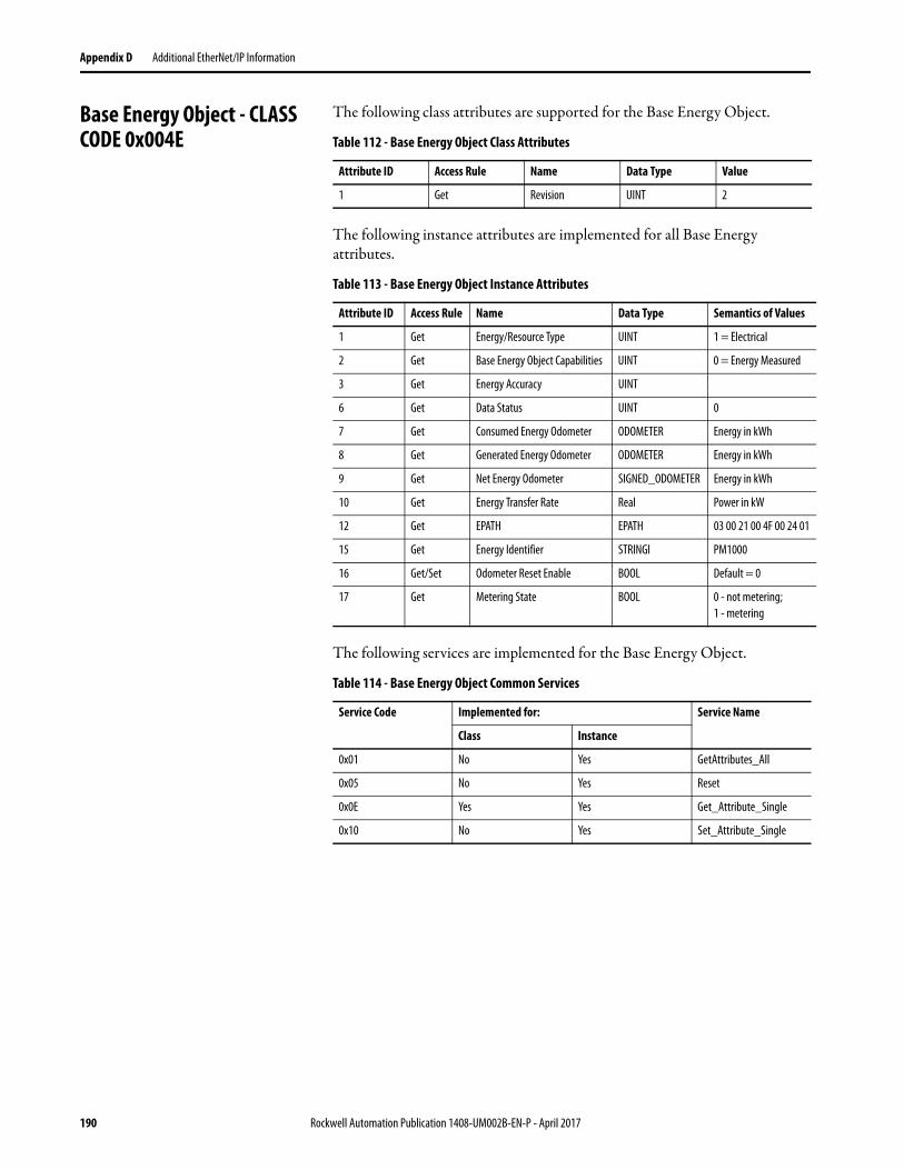
Appendix D Additional EtherNet/IP Information
Base Energy Object - CLASS CODE 0x004E
The following class attributes are supported for the Base Energy Object.
The following instance attributes are implemented for all Base Energy attributes.
The following services are implemented for the Base Energy Object.
Table 112 - Base Energy Object Class Attributes
Attribute ID Access Rule Name Data Type Value
1 Get Revision UINT 2
Table 113 - Base Energy Object Instance Attributes
Attribute ID Access Rule Name Data Type Semantics of Values
1 Get Energy/Resource Type UINT 1 = Electrical
2 Get Base Energy Object Capabilities UINT 0 = Energy Measured
3 Get Energy Accuracy UINT
6 Get Data Status UINT 0
7 Get Consumed Energy Odometer ODOMETER Energy in kWh
8 Get Generated Energy Odometer ODOMETER Energy in kWh
9 Get Net Energy Odometer SIGNED_ODOMETER Energy in kWh
10 Get Energy Transfer Rate Real Power in kW
12 Get EPATH EPATH 03 00 21 00 4F 00 24 01
15 Get Energy Identifier STRINGI PM1000
16 Get/Set Odometer Reset Enable BOOL Default = 0
17 Get Metering State BOOL 0 - not metering; 1 - metering
Table 114 - Base Energy Object Common Services
Service Code Implemented for: Service Name
Class Instance
0x01 No Yes GetAttributes_All
0x05 No Yes Reset
0x0E Yes Yes Get_Attribute_Single
0x10 No Yes Set_Attribute_Single
190 Rockwell Automation Publication 1408-UM002B-EN-P - April 2017

Additional EtherNet/IP Information Appendix D
The following table describes the Get_Attributes_All response.
Table 115 - Base Energy Object Class Attributes Get_Attributes_All Response
Attribute ID Data Type Name Value
1 UINT Energy/Resource Type Attribute 1 value
2 UINT Base Energy Object Capabilities
Attribute 2 value
3 UINT Energy Accuracy Attribute 3 value
4 UINT Energy Accuracy Basis 0
5 REAL Full Scale Reading 0
6 UINT Data Status Attribute 6 value
7 ODOMETER Consumed Energy Odometer
Attribute 7 value
8 ODOMETER Generated Energy Odometer
Attribute 8 value
9 SIGNED_ODOMETER Net Energy Odometer Attribute 9 value
10 REAL Energy Transfer Rate Attribute 10 value
11 REAL Energy Transfer Rate User Setting
0
12 STRUCT of: Energy Type Specific Object Path
Attribute 12 value
UINT Path Size
Padded EPATH Path
13 UINT Energy Aggregation Path Array Size
0
14 STRUCT of: Energy Type Specific Object Path
0
UINT Path Size
Padded EPATH Path
15 STRINGI Energy Identifier Attribute 15 value
16 BOOL Odometer Reset Enable Attribute 16 value
17 BOOL Metering State Attribute 17 value
18 UINT Extended Data Status 0
Rockwell Automation Publication 1408-UM002B-EN-P - April 2017 191

Appendix D Additional EtherNet/IP Information
Electrical Energy Object - CLASS CODE 0x004F
The following class attributes are supported for the Electrical Energy Object.
The following instance attributes are implemented for all Electrical Energy attributes.
Table 116 - Electrical Energy Object Class Attributes
Attribute ID Access Rule Name Data Type Value
1 Get Revision UINT 2
Table 117 - Electrical Energy Object Instance Attributes
Attribute ID Access Rule Name Data Type Semantics of Values
1 Get Real Energy Consumed Odometer
ODOMETER Energy in kWh
2 Get Real Energy Generated Odometer
ODOMETER Energy in kWh
3 Get Real Energy Net Odometer
SIGNED_ODOMETER Energy in kWh
4 Get Reactive Energy Consumed Odometer
ODOMETER Energy in kWh
5 Get Reactive Energy Generated Odometer
ODOMETER Energy in kWh
6 Get Reactive Energy Net Odometer
SIGNED_ODOMETER Energy in kWh
7 Get Apparent Energy Odometer
ODOMETER Energy in kWh
9 Get Line Frequency Real Unit: HZ
10 Get L1 Current Real Amps (A)
11 Get L2 Current Real Amps (A)
12 Get L3 Current Real Amps (A)
13 Get Average Current Real Amps (A)
14 Get Percent Current Unbalance
Real Percent
15 Get L1-N Voltage Real Volts (V)
16 Get L2-N Voltage Real Volts (V)
17 Get L3-N Voltage Real Volts (V)
18 Get Average L-N Voltage Real Volts (V)
19 Get L1-L2 Voltage Real Volts (V)
20 Get L2-L3 Voltage Real Volts (V)
21 Get L3-L1 Voltage Real Volts (V)
22 Get Average L-L Voltage Real Volts (V)
23 Get Percent Voltage Unbalance
Real Percent
24 Get L1 Real Power Real Watts (W)
25 Get L2 Real Power Real Watts (W)
26 Get L3 Real Power Real Watts (W)
27 Get Total Real Power Real Watts (W)
28 Get L1 Reactive Power Real Volt-amps reactive (VAR)
192 Rockwell Automation Publication 1408-UM002B-EN-P - April 2017
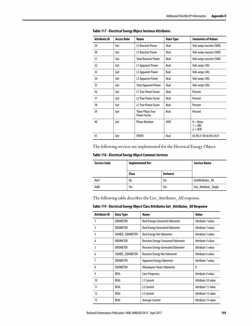
Additional EtherNet/IP Information Appendix D
The following services are implemented for the Electrical Energy Object.
The following table describes the Get_Attributes_All response.
29 Get L2 Reactive Power Real Volt-amps reactive (VAR)
30 Get L3 Reactive Power Real Volt-amps reactive (VAR)
31 Get Total Reactive Power Real Volt-amps reactive (VAR)
32 Get L1 Apparent Power Real Volt-amps (VA)
33 Get L2 Apparent Power Real Volt-amps (VA)
34 Get L3 Apparent Power Real Volt-amps (VA)
35 Get Total Apparent Power Real Volt-amps (VA)
36 Get L1 True Power Factor Real Percent
37 Get L2 True Power Factor Real Percent
38 Get L3 True Power Factor Real Percent
39 Get Three Phase True Power Factor
Real Percent
40 Get Phase Rotation UINT 0 = None1 = ABC2 = ACB
41 Get EPATH Real 03 00 21 00 4e 00 24 01
Table 118 - Electrical Energy Object Common Services
Service Code Implemented for:
Service Name
Class Instance
0x01 No Yes GetAttributes_All
0x0E Yes Yes Get_Attribute_Single
Table 119 - Electrical Energy Object Class Attributes Get_Attributes_All Response
Attribute ID Data Type Name Value
1 ODOMETER Real Energy Consumed Odometer Attribute 1 value
2 ODOMETER Real Energy Generated Odometer Attribute 2 value
3 SIGNED_ODOMETER Real Energy Net Odometer Attribute 3 value
4 ODOMETER Reactive Energy Consumed Odometer Attribute 4 value
5 ODOMETER Reactive Energy Generated Odometer Attribute 5 value
6 SIGNED_ODOMETER Reactive Energy Net Odometer Attribute 6 value
7 ODOMETER Apparent Energy Odometer Attribute 7 value
8 ODOMETER Kiloampere-Hours Odometer 0
9 REAL Line Frequency Attribute 9 value
10 REAL L1 Current Attribute 10 value
11 REAL L2 Current Attribute 11 value
12 REAL L3 Current Attribute 12 value
13 REAL Average Current Attribute 13 value
Table 117 - Electrical Energy Object Instance Attributes
Attribute ID Access Rule Name Data Type Semantics of Values
Rockwell Automation Publication 1408-UM002B-EN-P - April 2017 193

Appendix D Additional EtherNet/IP Information
14 REAL Percent Current Unbalance Attribute 14 value
15 REAL L1-N Voltage Attribute 15 value
16 REAL L2-N Voltage Attribute 16 value
17 REAL L3-N Voltage Attribute 17 value
18 REAL Average L-N Voltage Attribute 18 value
19 REAL L1-L2 Voltage Attribute 19 value
20 REAL L2-L3 Voltage Attribute 20 value
21 REAL L3-L1 Voltage Attribute 21 value
22 REAL Average L-L Voltage Attribute 22 value
23 REAL Percent Voltage Unbalance Attribute 23 value
24 REAL L1 Real Power Attribute 24 value
25 REAL L2 Real Power Attribute 25 value
26 REAL L3 Real Power Attribute 26 value
27 REAL Total Real Power Attribute 27 value
28 REAL L1 Reactive Power Attribute 28 value
29 REAL L2 Reactive Power Attribute 29 value
30 REAL L3 Reactive Power Attribute 30 value
31 REAL Total Reactive Power Attribute 31 value
32 REAL L1 Apparent Power Attribute 32 value
33 REAL L2 Apparent Power Attribute 33 value
34 REAL L3 Apparent Power Attribute 34 value
35 REAL Total Apparent Power Attribute 35 value
36 REAL L1 True Power Factor Attribute 36 value
37 REAL L2 True Power Factor Attribute 37 value
38 REAL L3 True Power Factor Attribute 38 value
39 REAL Three Phase True Power Factor Attribute 39 value
40 UINT Phase Rotation Attribute 40 value
41 STRUCT of: Associated Base Energy Object Path Attribute 41 value
UINT Path Size
Padded EPATH Path
Table 119 - Electrical Energy Object Class Attributes Get_Attributes_All Response
Attribute ID Data Type Name Value
194 Rockwell Automation Publication 1408-UM002B-EN-P - April 2017

Additional EtherNet/IP Information Appendix D
TCP/IP Interface Object - CLASS CODE 0x00F5
The following class attributes are supported for the TCP/IP Interface Object.
The following instance attributes are implemented for all TCP/IP Interface attributes.
Table 120 - TCP/IP Interface Object Class Attributes
Attribute ID Access Rule Name Data Type Value
1 Get Revision UINT 4
2 Get Max Instance UINT 1
3 Get Number of Instances UINT 1
Table 121 - TCP/IP Interface Object Instance Attributes
Attribute ID Access Rule Data Type Name Value
1 Get DWORD Interface status
2 Get DWORD Configuration Capability
3 Get DWORD Configuration Control
4 Get STRUCT of: Physical Link Object
UINT Path size
Padded EPATH Path
5 Get STRUCT of: Interface Configuration
UDINT IP Address
UDINT Network Mask
UDINT Gateway Address
UDINT Name Server
UDINT Name Server 2
STRING Domain Name
6 Get STRING Host Name
8 Get USINT TTL Value
9 Get STRUCT of: Mcast Config
USINT Alloc Control
USINT Reserved
UINT Num Mcast
UDINT Mcast Start Addr
10 Get BOOL SelectAcd
11 Get STRUCT of: LastConflictDetected
USINT AcdActivity
Array of 6 USINT RemoteMAC
ARRAY of 28 USINT ArpPdu
Rockwell Automation Publication 1408-UM002B-EN-P - April 2017 195

Appendix D Additional EtherNet/IP Information
The following services are implemented for the TCP/IP Interface object.
Table 122 - TCP/IP Interface Object Common Services
Service Code Implemented for: Service Name
Class Instance
0x01 No Yes GetAttributes_All
0x0E Yes Yes Get_Attribute_Single
Table 123 - TCP/IP Interface Object Class Attributes Get_Attributes_All Response
Attribute ID Data Type Name Value
1 DWORD Interface status
2 DWORD Configuration Capability
3 DWORD Configuration Control
4 STRUCT of: Physical Link Object
UINT Path size
Padded EPATH Path
5 STRUCT of: Interface Configuration
UDINT IP Address
UDINT Network Mask
UDINT Gateway Address
UDINT Name Server
UDINT Name Server 2
STRING Domain Name
6 STRING Host Name
7 6 octets Safety Network Number
8 USINT TTL Value
9 STRUCT of: Mcast Config
USINT Alloc Control
USINT Reserved
UINT Num Mcast
UDINT Mcast Start Addr
10 BOOL SelectAcd
11 STRUCT of: LastConflictDetected
USINT AcdActivity
Array of 6 USINT RemoteMAC
ARRAY of 28 USINT ArpPdu
12 BOOL EtherNet/IP QuickConnect
13 UINT Encapsulation Inactivity Timeout
196 Rockwell Automation Publication 1408-UM002B-EN-P - April 2017

Additional EtherNet/IP Information Appendix D
Ethernet Link Object - CLASS CODE 0x00F6
The following class attributes are supported for the Ethernet Link Object.
The following instance attributes are implemented for all Ethernet Link Object attributes.
The following services are implemented for the TCP/IP Interface object.
Table 124 - Ethernet Link Object Class Attributes
Attribute ID Access Rule Name Data Type Value
1 Get Revision UINT 3
2 Get Max Instance UINT 1
3 Get Number of Instances UINT 1
Table 125 - Ethernet Link Object Instance Attributes
Attribute ID Access Rule Name Data Type Value
1 Get Interface Speed UDINT
2 Get Interface Flags DWORD
3 Get Physical Address ARRAY of 6 USINTs
6 Get Interface Control STRUCT of:
Control Bits WORD
Forced Interface Speed
UINT
7 Get Interface Type USINT
8 Get Interface State USINT
9 Get Admin State USINT
10 Get Interface Label SHORT_STRING
Table 126 - Ethernet Link Object Common Services
Service Code Implemented for: Service Name
Class Instance
0x01 No Yes GetAttributes_All
0x0E Yes Yes Get_Attribute_Single
Rockwell Automation Publication 1408-UM002B-EN-P - April 2017 197

Appendix D Additional EtherNet/IP Information
Table 127 - Ethernet Link Object Class Attributes Get_Attributes_All Response
Attribute ID Data Type Name Value
1 UDINT Interface Speed
2 DWORD Interface Flags
3 ARRAY of 6 USINTs Physical Address
4 STRUCT of: Interface Counters
UDINT In Octets
UDINT In Ucast Packets
UDINT In NUcast Packets
UDINT In Discards
UDINT In Errors
UDINT In Unknown Protos
UDINT Out Octets
UDINT Out Ucast Packets
UDINT Out NUcast Packets
UDINT Out Discards
UDINT Out Errors
5 STRUCT of: Media Counters
UDINT Alignment Errors
UDINT FCS Errors
UDINT Single Collisions
UDINT Multiple Collisions
UDINT SQE Test Errors
UDINT Deferred Transmissions
UDINT Late Collisions
UDINT Excessive Collisions
UDINT MAC Transmit Errors
UDINT Carrier Sense Errors
UDINT Frame Too Long
UDINT MAC Receive Errors
6 STRUCT of: Interface Control
WORD Control Bits
UINT Forced Interface Speed
7 USINT Interface Type
8 USINT Interface State
9 USINT Admin State
10 SHORT_STRING Interface Label
198 Rockwell Automation Publication 1408-UM002B-EN-P - April 2017

Additional EtherNet/IP Information Appendix D
Parameter Object - CLASS CODE 0x000F
The PowerMonitor 1000 unit supports the Parameter Object (0x0f ), which provides a known, public interface to the device readable or configuration data.
Table 128 - Class Attributes for the Parameter Object
Number Access Rule Name Data Type Description of Attribute Semantics of Values
1 Get Revision UINT Revision of object class definition This is revision 1
2 Get Maximum Instance UINT Maximum instance number of an object currently created in this class level of the device.
Maximum instance is 131 in PM1000.
8 Get Parameter Class Descriptor
WORD Bits that describe parameters. 0b00000011 (1)Individual Parameter instances ARE supported (2)All Full Parameter Attributes ARE supported.
9 Get Configuration Assembly Instance
UINT Instance number of the configuration assembly.
0 means a configuration assembly is not supported.
Table 129 - Instance Attributes for the Parameter Object
Number NV Access Rule Name Data Type Description of Attribute Supported Values
1 NV Set Parameter Value Data type specified in Descriptor, Data Type and Data Size.
Actual value of parameter. It can be read from or written to. See 3.1.4
2 NV Get Link Path Size USINT Size of link path. If this attribute is 0, then no link is specified.
Number of bytes (0x06)
3 NV Get Link Path Packet EPATH CIP path to the object from where this parameter's value is retrieved.
The Link Path is limited to 255 bytes
4 NV Get Descriptor Word Description of parameter. See 3.1.4
5 NV Get Data Type EPATH Data type code. See 3.1.4
6 NV Get Data Size USINT Number of bytes in Parameter Value See 3.1.4
7 NV Get Parameter Name String
SHORT_ STRING A human-readable string representing the parameter name.
See 3.1.4
8 NV Get Units String SHORT_ STRING Engineering Unit String. See 3.1.4
9 NV Get Help String SHORT_ STRING Help String. See 3.1.4
10 NV Get Minimum Value Data type Generally, the minimum value to which the parameter can be set.
See 3.1.4
11 NV Get Maximum Value Data type Generally, the maximum value to which the parameter can be set.
See 3.1.4
12 NV Get Default Value Data type The actual value the parameter is set to when the user wants the default for the parameter.
See 3.1.4
13 NV Get Scaling Multiplier UINT Multiplier for Scaling Factor. 0x01
14 NV Get Scaling Divisor UINT Divisor for Scaling Formula. 0x01
15 NV Get Scaling Base UINT Base for Scaling Formula. 0x01
16 NV Get Scaling Offset INT Offset for Scaling Formula. 0x00
17 NV Get Multiplier Link UINT Parameter Instance of Multiplier source. 0x00
18 NV Get Divisor Link UINT Parameter Instance of Divisor source. 0x00
19 NV Get Base Link UINT Parameter Instance of Base source. 0x00
20 NV Get Offset Link UINT Parameter Instance of Offset source. 0x00
21 NV Get Decimal Precision USINT Places to use when displaying the scaled engineering value. Also used to determine actual increment value so that incrementing a value causes a change in scaled engineering value to this precision.
0x00
Rockwell Automation Publication 1408-UM002B-EN-P - April 2017 199

Appendix D Additional EtherNet/IP Information
Refer to Appendix A, PowerMonitor 1000 Data Tables, for a listing of Parameter Object Instances (p. hhh)
File Object - CLASS CODE 0x0037
The following class attributes are supported for the File Object.
Table 130 - Parameter Object Common Services
Service Code (Hex)
Need in Implementation Service Name Description of Service
Class Instance
0x0E Required Required Get_Attribute_Single Gets the specified attributes of the class or the instance
0x10 N/A Required Set_Attribute_Single Modifies an attribute value.
0x01 N/A Required Get_Attributes_All Returns a predefined listing of this objects attributes
Table 131 - File Object Class Attributes
Attribute ID Access Rule Name Data Type Value
1 Get Revision UINT 1
2 Get Max Instance UINT 0xC8
3 Get Number of Instances UINT 1
6 Get Maximum ID Number Class Attributes
UINT 32
7 Get Maximum ID Number Instance Attributes
UINT 11
32 Get Directory Array of Struct
Instance Number UINT 0xC8
Instance_Name STRINGI 1, ‘eng’, 0xDA, 4, 18,‘EDS and Icon Files’
File_Name STRINGI 1, ‘eng’, 0xDA, 4, 6, ‘EDS.gz’
200 Rockwell Automation Publication 1408-UM002B-EN-P - April 2017

Additional EtherNet/IP Information Appendix D
Table 132 - Class Code 0x0037 Instance 0xC8 Attributes
Attribute ID
Access Rule
Name Data Type Value
1 Get State USINT 0 = Nonexistent 1 = File Empty (no file loaded) 2 = File Loaded 3 = Transfer Upload initiated 4 = Transfer Download initiated 5 = Transfer Upload in Progress 6 = Transfer Download in Progress 7 = Storing 8…255 = Reserved
2 Get Instance Name STRINGI 1, "eng", 0xDA, 4, 18, "EDS and Icon Files"
3 Get Instance Format Version
UINT 1
4 Get File Name STRINGI 1, "eng", 0xDA, 4, 6, "EDS.gz"
5 Get File Revision
USINT USINT
EDS File Revision
6 Get File Size UDINT EDS File Size
7 Get File Checksum INT EDS File Checksum
8 Get Invocation Method USINT 0
9 Get File Save Parameters BYTE 0
10 Get File Type USINT 1 = Read Only
11 Get File Encoding Format USINT 1 = Compressed EDS and Icon files for this device
Table 133 - File Object Common Services
Service Code (Hex)
Need in Implementation Service Name Description of Service
Class Instance
0x0E Required Required Get_Attribute_Single Gets the specified attributes of the class or the instance
0x10 N/A Required Set_Attribute_Single Modifies an attribute value
Table 134 - File Object Object-specific Services
Service Code (Hex)
Need in Implementation Service Name Description of Service
Class Instance
0x4B N/A Required Initiate_Upload Used to start a file upload
0x4C N/A Required Initiate_Download Used to start a file download
0x4F N/A Required Upload_Transfer Performs a file transfer upload
0x50 N/A Required Download_Transfer Performs a file transfer download
0x51 N/A Required Clear File Clears a loaded file
Rockwell Automation Publication 1408-UM002B-EN-P - April 2017 201

Appendix D Additional EtherNet/IP Information
Notes:
202 Rockwell Automation Publication 1408-UM002B-EN-P - April 2017

Index
Aadministrative mode 51advanced configuration 125alarm log 74analog input configuration 123, 124, 165applications 7ASCII communication 44
BBC3 8before you begin 5billing and sub-billing 8
Ccalculating energy log depth 105catalog number and WIN 163Change Policy Holder 53change table password 80command table 137commands 81communication 31
Ethernet 33serial 31
communication command summaryDH485 84Modbus RTU serial 85optional EtherNet/IP 85optional Modbus/TCP Ethernet 85serial DF1 full-duplex slave 84serial DF1 half-duplex slave 84
communication overview 11ethernet 12serial 11
communication setup 59Ethernet 60RS-485 59
communication wiring 31Ethernet 33multi-drop 32point-to-point 32
configuration lock 9configuration lock input 79configure
DF1 full-duplex 113DF1 half-duplex 113EtherNet/IP network using Ethernet devices
driver 115EtherNet/IP network using EtherNet/IP
driver 115RSLinx software driver DH485 114
control power 30controller interface table 142cost allocation 7
current connectionssingle phase 27three phase 27
current sensing 25current unbalance 66
Ddata and time configuration 133data format
floating-point 84integer 84
data tableaccess 84addressing 83data format 84read 84write 84
data tables 121advanced configuration 125analog input configuration 123, 124, 165catalog number and WIN 163command table 137controller interface table 142data and time configuration 133demand results 149discrete results 143energy log results 153energy results 148ethernet configuration 129load factor log results 159log configuration 134log request table 140min/max log results 157min/max parameter list 158power results 147serial RS-485 configuration 128single element password write 164time of use log results apparent energy and
demand 162time of use log results reactive energy and
demand 161time of use log results real energy and
demand 160unit run status results 155unit status log results 150user-configured 107volts, amps, frequency results 146wiring diagnostics results 144write error status results 154
date and time 67daylight saving time 68demand metering 63demand results 149DH485 11
communication rate 12maximum node address 12node addresses 12number of nodes 12
DHCP auto-addressing 60dimensions 19
Rockwell Automation Publication 1408-UM002B-EN-P - April 2017 203

Index
DIN rail 18mount 18
discrete results 143
EEM3 8energy log 69
calculating depth 105results 153
energy metering 61preset/set 81
energy results 148Ethernet communication 12, 33, 86
EtherNet/IP protocol 12Modbus TCP Protocol 12
Ethernet configuration 129explicit messaging 86
read write single or multiple elements 86RSLogix5 message setup PLC5 or SLC typed
read write 94RSLogix500 message setup PLC5 or SLC
typed read write 92RSLogix5000 message configuration PLC5 or
SLC typed read write 87RSLogix5000 message setup CIP generic 88setup 86
Ffactory defaults 78FactoryTalk EnergyMetrix 7features 8
hardware 8functions 8
Gground 33grounding 33
Hhardware features 8HyperTerminal 44HyperTerminal Private Edition 44
Iinitial setup 13
equipment needed 13LAN port 13temporary power 14
KKYZ output 9, 30, 75
force 81setup 76
LLCD
interface buttons 9viewing data 44
LCD screen 37LED See status indicatorload factor log 72
clear 81load factor log results 159load profiling 7log
data table 103log configuration 134log in 54log out 54log request table 140log status input changes 80
Mmanage users 53memory organization 83menu navigation 39message configuration
RSLogix5000 87message setup
RSLogix5 94RSLogix500 92RSLogix5000 88
metering result averaging 80min/max log 71
clear 81min/max log results 157min/max parameter list 158model functionality
10model types 8
BC3 8EM3 8TS3 8
modesdisplay mode 37edit mode 37, 43program mode 37, 42
modify Policy Holder 53module status indicator 9mount the unit 17
DIN rail mount 18panel mount 18
Nnetwork status indicator 9network time synchronization 69
204 Rockwell Automation Publication 1408-UM002B-EN-P - April 2017

Index
OOPC
browse tags 119topic setup 116
operational mode 51overcurrent protection 20, 30overview 7
Ppanel mount 18password size 53polarity 26Policy Holder 51Policy HolderLmodify 53power metering 65power results 147power system monitoring and control 8PuTTY software 44
Rread write
message type 86multiple elements 86single 86
reading logs 103log data table methodology 103
recommended torque 20restore factory default 9restore factory defaults 78RSLinx classic drivers configuration
113DF1 full-duplex 113DF1 half-duplex 113EtherNet/IP devices driver 115EtherNet/IP EtherNet/IP drivers 115
RSLinx Classic OPC server setup 115OPC topic 116
RSLogix5message setup 94
RSLogix500message setup 92
RSLogix5000message configuration 87message setup 88
Ssafety 7, 34security 51
log in 54log out 54policy options 55user types 52
security policy 51
serial communication 11, 31, 86auto-sense 11DF1 full-duplex 11DF1 half-duplex 11DH485 11Modbus RTU 11
serial port status indicator 9serial RS-485 port configuration 128setup 34
analog inputs 56demand 63example use LCD 41LCD screen 37menu map 39menu navigation 39optionsl software 35setup menus 49use communication 49use web browser 35
single element password write 164software
optional 35special wiring modes 28specifications 183standard inputs 29status indicator
module 9network 9serial port 9
status input 9status inputs 29, 76
setup 77
Ttable password 51TeraTerm 44terminal block layout 20terminal emulation software 44time of use log results
apparent energy and demand 162reactive energy and demand 161real energy and demand 160
time of use logs 73time zone information 131TOU logs 73
clear 81TS3 8
Uunit mounting 17
DIN rail mount 18panel mount 18
unit run status results 155unit setup 34
LCD screen 37menu map 39menu navigation 39optional software 35
Unit Status log 74
Rockwell Automation Publication 1408-UM002B-EN-P - April 2017 205
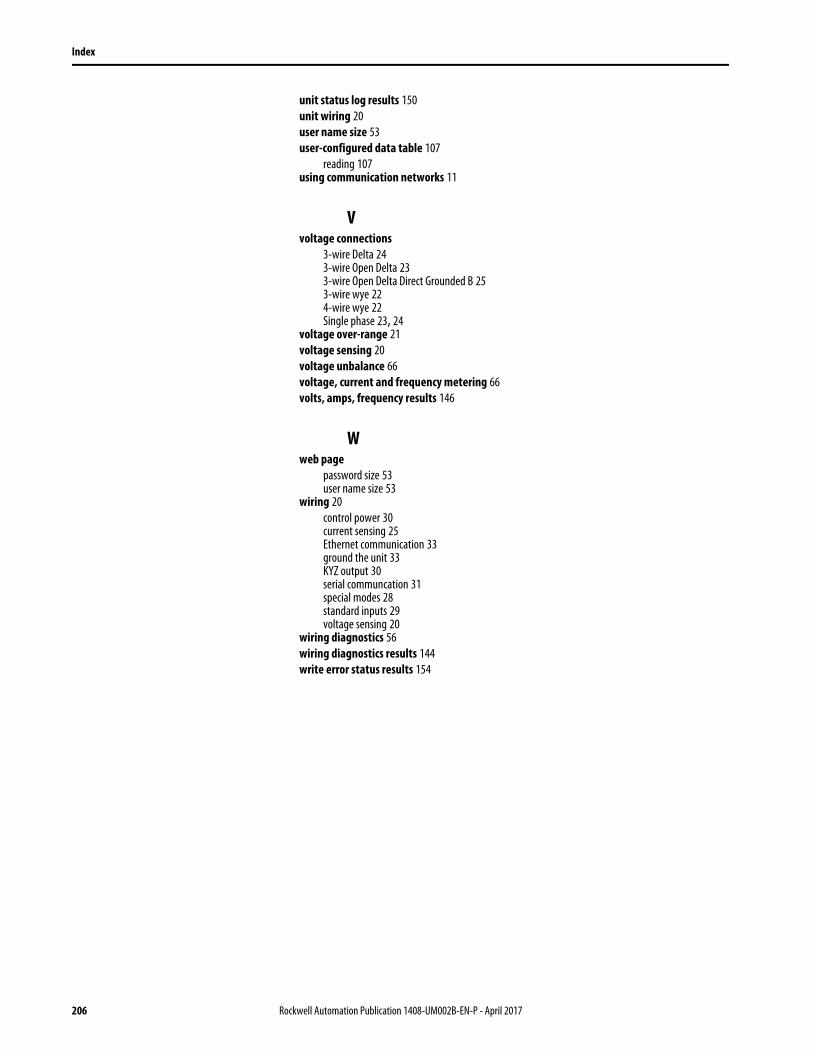
Index
unit status log results 150unit wiring 20user name size 53user-configured data table 107
reading 107using communication networks 11
Vvoltage connections
3-wire Delta 243-wire Open Delta 233-wire Open Delta Direct Grounded B 253-wire wye 224-wire wye 22Single phase 23, 24
voltage over-range 21voltage sensing 20voltage unbalance 66voltage, current and frequency metering 66volts, amps, frequency results 146
Wweb page
password size 53user name size 53
wiring 20control power 30current sensing 25Ethernet communication 33ground the unit 33KYZ output 30serial communcation 31special modes 28standard inputs 29voltage sensing 20
wiring diagnostics 56wiring diagnostics results 144write error status results 154
206 Rockwell Automation Publication 1408-UM002B-EN-P - April 2017


Publication 1408-UM002B-EN-P - April 2017 PN-xxxxxSupersedes Publication 1408-UM002A-EN-P - April 2015 Copyright © 2017 Rockwell Automation, Inc. All rights reserved. Printed in the U.S.A.
Rockwell Automation SupportUse the following resources to access support information.
Documentation FeedbackYour comments will help us serve your documentation needs better. If you have any suggestions on how to improve this document, complete the How Are We Doing? form at http://literature.rockwellautomation.com/idc/groups/literature/documents/du/ra-du002_-en-e.pdf.
Technical Support Center Knowledgebase Articles, How-to Videos, FAQs, Chat, User Forums, and Product Notification Updates. https://rockwellautomation.custhelp.com/
Local Technical Support Phone Numbers Locate the phone number for your country. http://www.rockwellautomation.com/global/support/get-support-now.page
Direct Dial Codes Find the Direct Dial Code for your product. Use the code to route your call directly to a technical support engineer. http://www.rockwellautomation.com/global/support/direct-dial.page
Literature Library Installation Instructions, Manuals, Brochures, and Technical Data. http://www.rockwellautomation.com/global/literature-library/overview.page
Product Compatibility and Download Center (PCDC)
Get help determining how products interact, check features and capabilities, and find associated firmware. http://www.rockwellautomation.com/global/support/pcdc.page
.
Rockwell Otomasyon Ticaret A.Ş., Kar Plaza İş Merkezi E Blok Kat:6 34752 İçerenköy, İstanbul, Tel: +90 (216) 5698400
Rockwell Automation maintains current product environmental information on its website at http://www.rockwellautomation.com/rockwellautomation/about-us/sustainability-ethics/product-environmental-compliance.page.
Allen-Bradley, Rockwell Software, Rockwell Automation, PowerMonitor, ControlLogix, PLC-5, SLC, FactoryTalk EnergyMetrix, RSLogix, Studio 5000 Logix Designer, and RSLinx, are trademarks of Rockwell Automation, Inc.
Trademarks not belonging to Rockwell Automation are property of their respective companies.


