81
https://ntrs.nasa.gov/search.jsp?R=20150015944 2018-05-29T20:32:55+00:00Z

https://ntrs.nasa.gov/search.jsp?R=20150015944 2018-05-29T20:32:55+00:00Z

NASA Armstrong Flight Research Center
A Message from the Center Director
Greetings and congratulations to the NASA Armstrong Flight
Research Center Summer 2015 Student Programs cohort!
Students like you—educated in the STEM disciplines of
science, technology, engineering and mathematics—are the
keys to America’s technological leadership and economic
growth in the 21st century. A gap remains between the growing
need for scientists, engineers, and other technically skilled
workers, and the available supply. This crisis has the potential to
affect U.S. global competitiveness and the national economy.
Our economy and our competitiveness hinge on continuing to fill
the pipeline with talented future leaders such as you.
NASA has always been blessed with skilled workers who have made us a world leader. Our program
mentors represent the best of these skilled workers. Mentoring is about unleashing the next generation to
go do great things. Good mentoring is an integrated group activity and one act can propagate through an
organization to create synergies. I see the skill of mentoring the development of the next generation as
creating bridges between people and providing them an environment to excel. I sincerely thank the
mentors this year for their efforts and support.
It's not just our skills that make us the leader, but our passion, our curiosity, our desire to reach the next
horizon, our diversity and inclusiveness, and our ability to make something greater of the whole than the
sum of our parts. You have continued your education for such work through your experiences here at
NASA Armstrong, and we have benefited from your participation.
As Alan C. Kay of Apple said, “The best way to predict the future is to invent it.” That is our mission, and
that is your assignment.
David D. McBride
Center Director
1
NASA Armstrong Flight Research Center
Programs Description
Aeronautics Scholarship ProgramThe Aeronautics Scholarship Program is part of NASA’s Aeronautics Research Mission
Directorate (ARMD), which has a goal of advancing the science of aeronautics and fostering new
generations of highly skilled scientists and engineers. As part of its commitment to mastering the
core competencies of aeronautics in all flight regimes, ARMD is undertaking the Aeronautics
Scholarship Program focused on aeronautical research and related degree programs at both the
undergraduate and graduate levels. The program awards $15,000 for each school year to
undergraduate students and $35,000 for each school year to graduate students. Students
awarded the scholarship are provided an internship opportunity with a stipend at a NASA center
performing aeronautical research.
Aerospace Education Research Operations (AERO) AssociateThe AERO Institute is a consortium to produce the next generation of the aerospace workforce
and provides 10-week summer internships to exceptional undergraduate and graduate students
with STEM related career aspirations. Summer jobs are assigned based on each participant’s
skills and abilities and provide students with a comprehensive technical education by allowing
them to participate in leading edge aerospace research in an industrial setting. Strategic
partners in the AERO include NASA Dryden Flight Research Center, NASA Ames Research
Center, and the City of Palmdale, California.
California Space Grant Consortium CASGCThe CaSGC mission is to serve as a crosscutting and integration agent in
California to bring the aerospace-related content, technical expertise, and
application environment of NASA’s scientific and technical Enterprises to the
educational community and the general public.
2
NASA Armstrong Flight Research Center
Programs Description
Curriculum Improvements Partnership Award for
the Integration of Research (CIPAIR)CIPAIR assists two- and four-year minority institutions with strengthening their science,
technology, engineering and mathematics academic fields and technical programs. Funding is
used to increase the quantity and quality of Science, Technology, Engineering, and Math (STEM)
curricula. CIPAIR brings underrepresented and underserved college students and their teachers to
NASA centers for research projects aimed at improving curriculums for future generations of
students. Students gain the confidence, knowledge and skills necessary to understand conceptual
frameworks, apply skills to manage projects and implement solutions to maximize efficiency.
Harriet Jenkins Pre- Doctoral Fellowship ProgramThe Jenkins Pre-doctoral Fellowship Project, or JPFP, seeks to increase the number of graduate
degrees awarded to underrepresented persons (women, minorities and persons with disabilities)
in the science, technology, engineering and mathematics, or STEM, disciplines. The ultimate goal
is to increase the U.S. talent pool by developing a more inclusive, multicultural and sustainable
STEM workforce.
Multidisciplinary Aeronautics Research Team Initiative (MARTI)The NASA MARTI program offers an immersive, integrated, multi-disciplinary opportunity for
students with career aspirations in the national aeronautics enterprise. The academy prepares
aspiring young professionals for employment in aeronautics by providing opportunities for direct
science and engineering experience with an awareness of the complex managerial, political,
financial, social, and human issues faced by current and future aerospace programs. Participants
in the program must be enrolled in Aeronautical, Aerospace Engineering or other related
engineering discipline. Research Associates work as a team on a multi-faceted problem as
guided by professional scientists and engineers..
3

NASA Armstrong Flight Research Center
Programs Description
NSF CRESTThe Centers of Research Excellence in Science and Technology (CREST) program provides a
substantial source of Federal support for research at minority-serving institutions across the United
States. By facilitating research projects in science, technology, engineering and mathematics
(STEM) disciplines with multi-year, multi-million dollar cooperative agreements, the main goal of
CREST and its awardees is to build the research competitiveness of minority-serving institutions
while increasing the recruitment and retention of individuals from diverse backgrounds in STEM
study and STEM-based career
Universities Space Research Association (USRA)NASA awarded a cooperative agreement to Universities Space Research Association to support
the agency’s education internship programs. USRA is a recognized leader in administering
educational opportunities for students and teachers that lead to employment with NASA.
UpWard Bound ProgramUpward Bound serves high school students from low-income families in which neither parent has
earned a bachelor's degree. CSUSB Upward Bound provides free services that include: skills
building, personal development and leadership activities, college visits, assistance with the college
and financial aid application process, and a Summer University Program, which allows students to
work on their academics to ensure college readiness.
4

NASA Armstrong Flight Research Center
John Giammarino P. 7
Joaquin Martinez P. 8
Benjamin Martins P. 9
Michael Arreola-Zamora P. 10
Nathan Bell P. 11
Olivia Bosma P. 12
Taylor Jenson P. 12
Alexander Chen P. 12
Tyler Clinkaberry P. 13
Or Dantsker P. 14
Bryce Doerr P. 15
Louis Edelman P. 16
Lindsay Flasch P. 17
Logan Francisco P. 18
Jeremy Germita P. 19
Nicole Gillian P. 20
Darian Grisso P. 21
James Hamory P. 22
Nicholas Horn P. 23
John Jackson P. 24
Saba Janamian P. 25
Victoria Jenne P. 26
Emma Ruano P. 26
Lynn Valkov P. 26
Robert Kotcher P. 27
Caleb Lloyd P. 28
Loren Newton P. 28
Kurt Pauer P. 28
Jonathan Lokos P. 29
Emily Nichols P. 30
Dhvani Patel P. 31
Christian Pereira P. 32
Tommy Pestolesi P. 33
Kyle Lukacovic P. 34
Alex Petrik P. 34
Shelby Worrell P. 34
Pamela Ruffner P. 35
Savannah Shively P. 36
Billy Sitz P. 37
Patrick Sosa P. 38
Nicholas Souza P. 39
Kyler Stephens P. 40
Ethan Williams P. 41
Madison Washburn P. 42
Jacob Wilson P. 43
Nicole Lopez P. 44
Kevin Collins P. 45
Joseph Martinez P. 46
Ana Escalera P. 47
Will Morris P. 47
Raziq Noorali P. 47
Joseph Piotrowski P. 47
Kelley Hashemi P. 48
Keenan Albee P. 49
Jonathan Zur P. 49
Kira Headrick P. 50
Clement Li P. 51
Kassidy McLaughlin P. 52
Alexandra Ocasio P. 52
Christopher Trumbull P. 53
5
Table of Contents

NASA Armstrong Flight Research Center
Kaixi Wang P. 54
Troy Kuhns P. 55
Timothy Nunez P. 56
Christy Ailman P. 57
William Alfano P. 58
Yasmin Alkusari P. 59
Sipanah Arutyunyan P. 60
Orlando Mielke P. 60
Hussein Nasr P. 60
Bogdan Pugach P. 60
Christopher Bryan P. 61
Benjamin Cobleigh P. 62
Rheanna Cowee P. 63
John Freudinger P. 64
Pablo Gonzalez P. 65
E. Etan Halberg P. 66
Waqqas Khan P. 67
David Kloesel P. 68
Michael Kloesel P. 68
Mandy Ledford P. 68
Heather Laffoon P. 69
Harrison Pauer P. 70
Karter Rohrer P. 71
Victor Ruiz P. 72
Ivan Salazar P. 73
Rachel Saltzman P. 74
Joshua Tanon P. 75
Eduardo Uribe-Saldana P. 75
Benjamin Wright P. 76
Carolina Guerrero P. 77
Diana Jerez P. 77
Steve Pastor P. 77
Jocelyn Ramirez P. 77
Jose Ramirez P. 77
Nestor Zuniga P. 77
6
Table of Contents, Continued
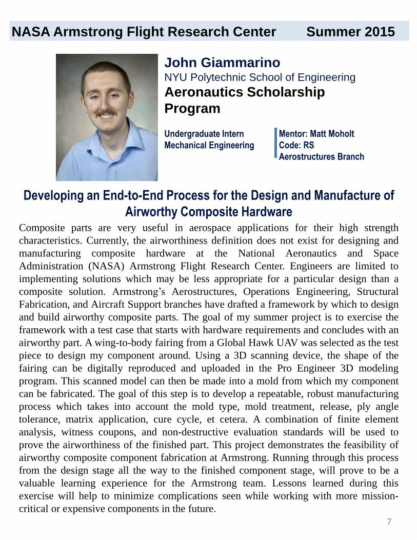
Composite parts are very useful in aerospace applications for their high strength
characteristics. Currently, the airworthiness definition does not exist for designing and
manufacturing composite hardware at the National Aeronautics and Space
Administration (NASA) Armstrong Flight Research Center. Engineers are limited to
implementing solutions which may be less appropriate for a particular design than a
composite solution. Armstrong’s Aerostructures, Operations Engineering, Structural
Fabrication, and Aircraft Support branches have drafted a framework by which to design
and build airworthy composite parts. The goal of my summer project is to exercise the
framework with a test case that starts with hardware requirements and concludes with an
airworthy part. A wing-to-body fairing from a Global Hawk UAV was selected as the test
piece to design my component around. Using a 3D scanning device, the shape of the
fairing can be digitally reproduced and uploaded in the Pro Engineer 3D modeling
program. This scanned model can then be made into a mold from which my component
can be fabricated. The goal of this step is to develop a repeatable, robust manufacturing
process which takes into account the mold type, mold treatment, release, ply angle
tolerance, matrix application, cure cycle, et cetera. A combination of finite element
analysis, witness coupons, and non-destructive evaluation standards will be used to
prove the airworthiness of the finished part. This project demonstrates the feasibility of
airworthy composite component fabrication at Armstrong. Running through this process
from the design stage all the way to the finished component stage, will prove to be a
valuable learning experience for the Armstrong team. Lessons learned during this
exercise will help to minimize complications seen while working with more mission-
critical or expensive components in the future.
Undergraduate Intern
Mechanical Engineering
Mentor: Matt Moholt
Code: RS
Aerostructures Branch
Developing an End-to-End Process for the Design and Manufacture of
Airworthy Composite Hardware
John GiammarinoNYU Polytechnic School of Engineering
Aeronautics Scholarship
Program
NASA Armstrong Flight Research Center Summer 2015
7

The mass moment of inertia is a measure of how much an object will resist
angular acceleration in a specified axial direction. This property can be used
in flight to better understand how control surfaces of an aircraft will affect the
pitch, roll, and yaw of the aircraft. My project over the summer was to create
multiple technical models, such as an inertia and aerodynamic model, of an
aircraft called Hugh . To calculate the inertia of the aircraft, the aircraft was
hung from a test rig, and then the nose of the aircraft was perturbed to initiate
a lightly damped oscillatory response. The measured frequency of the
response was used to calculate the inertia in that axis. The aerodynamic
model of the aircraft was estimated using flight data gathered on the aircraft
during a previous flight and a program called Parameter Estimation (PEST).
PEST uses aircraft dimensions and moments of inertia with the equations of
motion to iterate aerodynamic derivatives until the estimated time history
responses match the flight data. These aerodynamic derivatives are then used
to create an aerodynamic model of the aircraft. These models will allow any
future researcher working on or conducting experiments with Hugh to have a
complete model of the dynamics of the aircraft and hence allow them to
conduct more precise experiments.
Joaquin MartinezCalifornia State University Long Beach
Aeronautics Scholarship
Program
Undergraduate Intern
Mechanical Engineering
Mentor: Tim Cox
Code: RC
Dynamics and Controls
Developing a Research Test Bed for Small UAV’s
NASA Armstrong Flight Research Center Summer 2015
8
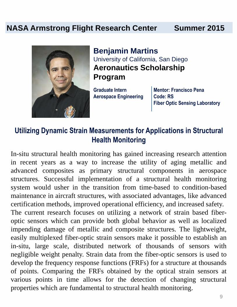
In-situ structural health monitoring has gained increasing research attention
in recent years as a way to increase the utility of aging metallic and
advanced composites as primary structural components in aerospace
structures. Successful implementation of a structural health monitoring
system would usher in the transition from time-based to condition-based
maintenance in aircraft structures, with associated advantages, like advanced
certification methods, improved operational efficiency, and increased safety.
The current research focuses on utilizing a network of strain based fiber-
optic sensors which can provide both global behavior as well as localized
impending damage of metallic and composite structures. The lightweight,
easily multiplexed fiber-optic strain sensors make it possible to establish an
in-situ, large scale, distributed network of thousands of sensors with
negligible weight penalty. Strain data from the fiber-optic sensors is used to
develop the frequency response functions (FRFs) for a structure at thousands
of points. Comparing the FRFs obtained by the optical strain sensors at
various points in time allows for the detection of changing structural
properties which are fundamental to structural health monitoring.
Graduate Intern
Aerospace Engineering
Mentor: Francisco Pena
Code: RS
Fiber Optic Sensing Laboratory
Utilizing Dynamic Strain Measurements for Applications in Structural
Health Monitoring
Benjamin MartinsUniversity of California, San Diego
Aeronautics Scholarship
Program
NASA Armstrong Flight Research Center Summer 2015
9

The purpose of this project is to construct a Brayton cycle thermodynamic
model of a turbine engine. Using a fifteen pounds-force micro-turbine
engine, data was obtained and used to theorize the operation of larger
turbines. The engine controller is a necessity to the operation of the turbine
and receives inputs: RPM, temperature, and user throttle. This information is
used to control the engine fuel pump flow rate. Modern engine controllers
have an automated fuel ramp sequence allowing users to avoid damaging the
turbine. This ramp sequence gradually rises as each received input rises,
informing the fuel pump and user if any errors occur (Ex. temperature too
high). The knowledge and simulation of these ramping functions will assist
in the implementation of a hybrid turbo electric airplane control system. This
will help reduce both emissions and the consumption of fuel for larger
aircrafts. The use of this information can make future aircrafts more efficient
by allowing them to travel greater distances. With further investigation, this
model can be used as a basis for turbine engines used in the future for
electric powered airplanes.
Undergraduate Intern
Mathematics
Astrophysics
Mentor: Kurt Kloesel
Code: RA
Aerodynamics and Propulsion
Thermodynamic Modeling of a Turbine Engine Using the Brayton Cycle
Michael Arreola-ZamoraUniversity of California, Los Angeles
Aerospace Education Research
Operations (AERO) Associates
NASA Armstrong Flight Research Center Summer 2015
10

A propeller functions like a rotating wing, creating thrust as it rotates in the
same way that a wing produces lift. Unlike a wing, however, the velocity of
a propeller blade is not constant all the way out to the tip. The blade velocity
increases with the radius, causing most of the thrust to be generated nearer to
the blade tip. This velocity causes an increase in induced drag and torque.
Accordingly, there is a need for modifications to propeller design to mitigate
these problems and increase propeller efficiencies. The objective of this
project is to design a more efficient propeller by applying techniques
previously used on the Prandtl wing design. Specifically, the bell-shaped lift
distribution of the Prandtl will be applied to the blades. Using XROTOR , a
propeller design and analysis program, the blade geometry will be altered in
iterations and analyzed until the desired thrust distribution is achieved.
Primarily, the blade twist will be altered. The propeller will then be tested to
determine its actual performance, and the required changes will be made to
the propeller design. By the end of the design process, a propeller will have
been produced displaying increased thrust with reduced induced drag and
torque.
Graduate Intern
Physics
Mentor: Al Bowers
Code: R
Research and Engineering
Directorate
Prandtl Propeller Design
Nathan BellUniversity of California, Los Angeles
Aerospace Education Research
Operations (AERO) Associates
NASA Armstrong Flight Research Center Summer 2015
11

Birds have kept the secret of flight locked in their wings for millions of
years. Understanding the flight of birds seems simple enough, but with a
slightly different structure used for human flight, it is no easy task. The
Prandtl wing is the first refined aircraft of its kind, complete with no vertical
tail and wing twist/taper, mimicking a similar body structure as birds.
When an aircraft is in the research stages, pilots perform doublets, which are
certain maneuvers that agitate roll, pitch, and yaw. For Prandtl, the remote
control surface still produces noise. With autopilot included, noise can be
reduced and human error can be eliminated, so data analysis becomes easier.
One way to make sure autopilot works is to create a simulation that will
allow for accurate predictions as to how the Prandtl wing behaves with
autopilot. Simulations provide valuable information, by both providing
confidence in the system and revealing issues in the program that can be
evaluated. With a simulation, other autopilot functions including the rumble
can be analyzed for correct behaviors and proper responses.
Taylor Jensen2
Antelope Valley College
Simulation
Mentor: Albion Bowers
Code: R
Research and Engineering Directorate
Alexander Chen3
Duke University
Olivia Bosma1
Embry Riddle Aeronautical
Univeristy
NASA Armstrong Flight Research Center Summer 2015
Aerospace Education Research Operations (AERO) Associates1,3
Universities Space Research Association (USRA) 2
Undergraduate Interns
Aerospace Engineering1
Engineering & Law2
Biomedical Engineering3
12

In the Range Operations Branch, communication systems are very important
in ensuring everything runs smoothly by making sure the entire team can
stay in contact, and that data can be collected from aircraft. Gregory
Strombo supports improvements to the International Space Station (ISS)
Very High Frequency (VHF) communication system, and he is working with
me to create a Simulink model of the Human Space Flight V1 Emergency
Communications System. This project is intended to improve system
documentation by creating a block diagram that numerically describes the
radio frequency characteristics of each component, and the system as a
whole. The Simulink model will enable the user to quickly evaluate alternate
configurations, enhancements, or be incorporated into larger models for
inter-system analyses. This allows for further improvement of the system,
and increasing the speed at which improvements are made. Lastly, my
project will include an evaluation of the predicted system performance in
comparison to measured system performance. Model validation will consist
of comparing predicted signal loss and reflected power to measured system
S-parameters. This new capability will lead to better signal output and more
reliable communications with the ISS.
Radio Frequency Communications
NASA Armstrong Flight Research Center Summer 2015
Undergraduate Intern
Computer Engineering
Mentor: Bob Guere
Code: MR
Range Operations
Tyler ClinkaberryUC Santa Cruz
Aerospace Education Research
Operations (AERO) Associates
13

NASA Armstrong Flight Research Center Summer 2015
The Leading Edge Asynchronous Propeller Technology (LEAPTech) project
will test the premise that tighter propulsion-airframe integration, made
possible with electric power, will deliver improved efficiency and safety, as
well as environmental and economic benefits. An experimental wing, called
the Hybrid-Electric Integrated Systems Testbed (HEIST), was fabricated and
mounted on a specially modified truck to experimentally measure the
efficiency improvement. Instead of being installed in a wind tunnel, the
HEIST wing section will remain attached to load cells on a supporting truss
while the vehicle is driven at speeds up to 70 miles per hour across the
lakebed at NASA Armstrong. In order to assess the efficiency of the wing,
pressure taps were installed along circumference of several sections, inboard
and outboard of a wing mounted motor. Given the data generated by these
ports, I will calculate the pressure distribution along those sections, which
will be used in the future to determine the lift, drag, and moment created by
the wing. Performing this data reduction for a variety of wing and propulsion
configurations will help to judge the efficiency of the wing.
Or DantskerUniversity of Illinois
Graduate Intern
Aerospace Engineering
Mentor: James Murray
Code: RA
Aerodynamics and Propulsion
Branch
LEAPTech HEIST Wing Pressure Distribution
Aerospace Education Research
Operations (AERO) Associates
14
The primary objective of the PRANDTL-D aircraft simulation is to validate
Ludwig Prandtl’s theory that a bell-shaped lift distribution, as opposed to the
accepted elliptical lift distribution, across the aircraft wingspan is more
efficient for flight. The bell-shaped distribution causes proverse yaw, which
counteracts adverse yaw, eliminating the need for a rudder as the aircraft will
cease to yaw in an undesired direction during roll maneuvers. The
PRANDTL-D aircraft simulation and flight tests are the few ways to prove
the efficiency of the bell-shaped lift distribution. In order to verify the bell-
shaped lift distribution of the aircraft via simulation, the Coresim used in the
Simulation Branch will be adapted for the aircraft. Although the simulation
code has been refined with models of other aircraft, the simulation code must
accommodate the aerodynamics, mass, and control surfaces of the
PRANDTL-D aircraft. Aerodynamic and mass data will be taken from the
aircraft to simulate the aircraft accurately in the simulation environment. An
emphasis will be the testing of the aircraft simulation in a similar manner
with the flight tests to verify the flight data. This method will allow further
proof of the aircraft performance characteristics and support Prandtl’s theory
of a bell-shaped distribution as the overall most efficient lift distribution.
Mentor: Manny Castro
Code: ME
Simulation Engineering
Branch
Undergraduate Intern
Aerospace Engineering
Bryce DoerrUniversity of Minnesota-Twin Cities
Aerospace Education Research
Operations (AERO) Associates
NASA Armstrong Flight Research Center Summer 2015
PRANDTL-D Aircraft Flight Simulation
15
The Adaptive Compliant Trailing Edge (ACTE) experiment installed on the
SubsoniC Research Aircraft Testbed (SCRAT) G-III aircraft seeks to
demonstrate the structural effectiveness of a compliant lifting surface under
the unsteady aerodynamic loads of flight. ACTE technology promises a
lightweight high-lift device capable of spanwise lift distribution adjustment,
while maintaining a continuous outer mold line. As a part of the NASA
Environmentally Responsible Aviation initiative, ACTE promises a 3.5
percent drag reduction when retrofitted to an existing design and up to 12
percent on a clean sheet design.
The technology has flown over the past year and is preparing to extend the
test campaign into the transonic regime. Before the flight envelope can be
extended, it is necessary to analyze the performance of each ACTE
component in order to fully understand the aeroelastic dynamics and safety
of flight. The development of a flight condition cross-comparison tool allows
engineers to analyze how aerodynamic, vibrational, and structural
parameters influence each other and change over the flight envelope.
Undergraduate Intern
Aerospace Science &
Engineering
Mentor: Claudia Herrera
Code: RS
Aerostructures
ACTE Structural Dynamics Analysis
Louis EdelmanUniversity of California, Davis
Aerospace Education Research
Operations (AERO) Associates
NASA Armstrong Flight Research Center Summer 2015
16

Direct current (DC) power supplies are often used on test benches to give the
proper power to run the test equipment. Their use comes from their ability to
supply a range of voltages and currents at great accuracy. Power supplies are
a necessity for any lab environment where electronics are being tested. Many
types of complex circuits, especially those that are used in aviation, require
several different voltages to run. A circuit board may have a microcontroller,
a sensing unit, and a microprocessor that all require a different voltage.
Normally this would take two to three power supplies to run this board. Not
only would this take up a lot of space, but it would also use up a lot of power
supplies. The more power supplies being used on one project, the fewer that
will be available for other projects. A possible solution to this problem is to
create a power supply with more than one or two outputs. My project is to
help design a 7-output DC power supply. This power supply will give out
3.3V, 5V, 28V, ±15V, and ±adjustable voltage from .3V to 10.5V. The
constant voltages were chosen because they are some of the most commonly
used voltages for electronic equipment. Designing a power supply requires
knowledge of electronics and programming. The intern will need to learn to
program in Spin, the language of the microcontroller that will be used. This
microcontroller will control all aspects of the power supply, but the roll of
the intern will be to program the touch screen interface of the supply.
7-Output DC Power Supply
Undergraduate Intern
Electrical Engineering
Primary Mentor: Steve Jensen
Code: RT
Secondary Mentor: Fred Reaux
Code: RD
Research and Development
Lindsay FlaschThe University of Tulsa
Aerospace Education Research
Operations (AERO) Associates
NASA Armstrong Flight Research Center Summer 2015
17
Data communication is perhaps the most common yet unrecognized
procedure in the modern world. What most people don’t think about, though,
is all the technical interaction underneath the convenient and common
products and processes that go on every day. However, these processes aren’t
done automatically when on the forefront of research. For instance,
collecting data from numerous liquid metal strain gages (LMSG) , which
sense expansion and contraction, in a viable and cohesive manner requires
interfacing with multiple platforms. These platforms include the sensors
themselves to collect data, the microcontrollers to control the sensors, and
the method of data retrieval whether that be storing the raw data or exporting
the data to a computer to interpret it. My part is to use a Raspberry Pi (a
small, but powerful Linux-based computer) to interface between the
microcontrollers and the outside world wirelessly. The Raspberry Pi will be
“stacked” with eight LMSGs to both collect data and organize data in a
cohesive manner suitable for wireless communication to be interpreted by
LabView on a computer. By accomplishing this, researchers will be dealing
with a more convenient and standardized process to hopefully accelerate
research as field testing will not only be easier, but far more efficient.
Undergraduate Intern
Software Engineering
Mentor: Allen Parker
Code: RD
Electronic Instruments Systems
Raspberry Pi Communications and Data Retrieval
Logan FranciscoEmbry-Riddle Aeronautical University
Aerospace Education Research
Operations (AERO) Associates
NASA Armstrong Flight Research Center Summer 2015
18

Many instruments and sensors are quite sensitive to temperature conditions.
When operating these at temperatures higher than their rated temperatures,
we risk damaging critical components or gathering faulty data. The Strategic
Observatory for Infrared Astronomy (SOFIA) Water Vapor Monitor (WVM)
is no exception.
The temperature safety switch is a component designed to switch-adjust the
power to the WVM in response to the temperature. However, due to the
inductive properties of many electrical components, it is extremely
dangerous to rapidly switch an electrical system on and off. To mitigate this
effect, the temperature safety switch is designed to switch the system off at
105 degrees Fahrenheit, and not restore power until the system ambient
temperature returns to a safe lower threshold of 90 degrees Fahrenheit. This
method prevents a “ping-pong” effect in which power would be restored and
cut at a rapid rate due to the temperature rising and falling.
The temperature safety switch system aims to protect the electrical
components within the WVM from both temperature stresses and electrical
inductive stresses, to allow the WVM to safely gather consistent data
between flights.
SOFIA Water Vapor Monitor Temperature Safety Switch
Undergraduate Intern
Computer Science
Mentor: Matt Reaves
Code: RT
Vehicle Integration and Test
Jeremy GermitaAntelope Valley College
Aerospace Education Research
Operations (AERO) Associates
NASA headshot
hereDimensions:
2.59” x 2.08”
Horizontal
position: 1.14”
Vertical position:
2.05”
NASA Armstrong Flight Research Center Summer 2015
19
In the Photo Lab at the National Aeronautics and Space Administration
(NASA) Armstrong Flight Research Center, I am learning progressive
photography methods for documentation of aerospace engineering research.
Our primary goal is to document data on all aircraft when needed. It is critical
to get every shot for the crew of the aircraft, so the engineers can make the
right corrections. My role as an intern is to help see all of the photos we need
to document. The photo reflectors indoors, make sure our shutter speed,
aperture, and International Organization of Standardization (ISO) are all
correct for the right white balance. Our first project was photographing all of
the interns for their abstract photo by working with soft boxes in the lab. One
project we have shot a few times, now, is the Prandtl. Documenting the
Prandtl was a challenge of panning, zooming, focusing on the plane, and
keeping it in frame. Another project in the works is Viper; many engine tests
have been in process solving in flight air changes. We photograph many
different parts of the wings and engine on Viper. I am assisting one of my
mentors on a shoot of the X-34 Advanced Technology Demonstrator , which
has not moved in 15 years, to see if the spacecraft is salvageable. Our job was
to document every piece that is damaged inside and outside of the spacecraft .
The Photo Lab gets many random calls from different hangars who need
documentation before they can move on with their project.
Undergraduate Intern
Photography
Mentor: Jim Ross
Code: MI
Information Systems
Photography Documentation of Aerospace Engineering
Nicole GillianThe Art Institute of California – Orange County
Aerospace Education Research
Operations (AERO) Associates
NASA Armstrong Flight Research Center Summer 2015
20

Enacted in 1970, the Occupational Health and Safety Act allows every
employee a place free of recognized hazards that are causing, or are likely to
cause, death or harm. Because of this, the Industrial Hygiene department
works to protect Armstrong Flight Research Center (AFRC) employees from
hazards such as elevated noise, chemical, or laser exposure, as well as poor
ergonomic workstations that contribute to musculoskeletal diseases. This
summer, I have two primary focuses: evaluating and advising employees on
proper ergonomic workstations, and the consolidation and organization of
data from noise surveys collected over the last fifteen years to create a map
of measured areas. Industrial Hygiene, however, is just one part of the team
that helps to support the facility and its mission by supporting the workers.
With the guidance and influence of individuals in the Health Unit, Equal
Opportunity Office, and the Employee Assistance Program, I have created a
survey to evaluate what type of health problems (physical, mental, or social)
AFRC employees face. With this information, a program can then be
designed to address the needs of our employees to help them be most
efficient in their work. For example, this information can determine if
tobacco cessation workshops would be beneficial for Armstrong employees.
Undergraduate Intern
Health Science
Mentor: Miriam Rodon
Code: XV
Industrial Hygiene
Industrial Hygiene & Other Employee Resources
Darian GrissoSan José State University
Aerospace Education Research
Operations (AERO) Associates
NASA Armstrong Flight Research Center Summer 2015
21
During my time at the National Aeronautics and Space Administration (NASA)
Armstrong Flight Research Center (AFRC), I will be able to discover many
components of a video department and establish for myself a foundation upon which I
can build my career. I will be exposed to the many different aspects of the department
and become part of the working team for several projects. For example, I will be
working behind the scenes to run the weekly Brown Bag Seminars. I will be operating
cameras, working the sound board, setting up microphones, making adjustments to the
lighting, producing the live stream, directing the control room, and other necessary
tasks. This is one of the more exciting parts of my summer job, and I look forward to
doing what needs to be done to make each seminar a success.
One of the more menial tasks I have this summer is to digitize old footage of NASA
projects and seminars, and produce DVDs equipped with closed captions. I will be
aiding in the process of ingesting the film archive to a new and modern platform. This
process involves borrowing tapes from the tape libraries, making digital copies of the
old footage, ordering transcripts of the videos to make closed captions, saving the files
on the server, and burning new DVDs. This project contributes to the NASA mission
of innovation and improvement for the future, as digitizing old footage preserves the
documentation of NASA accomplishments and keeps AFRC up to date with modern
technology.
This internship gives me the opportunity to shadow the department videographers and
witness firsthand what a career in the video field entails. I also get to be a
videographer myself as we film and document the Prandtl project that some of the
other interns are working on. These experiences will benefit me greatly as I begin to
pursue a career in this field.
High School Graduate
Communications- Electronic
Media
Mentor: Lori Losey
Code: MI
Information Systems
Tastes Like Videography
James HamoryThe Master’s College
Aerospace Education Research
Operations (AERO) Associates
NASA Armstrong Flight Research Center Summer 2015
22
The Adaptive Compliant Trailing Edge (ACTE) project modified a
Gulfstream III (G-III) aircraft with a new flexible flap that creates a seamless
transition between the flap and the wing. As with any new modification, it is
crucial to ensure that the aircraft will not become overstressed in flight. To
test this, StarCCM – a computational fluid dynamics (CFD) software
program – was used to calculate aerodynamic data for the aircraft at given
flight conditions. The CFD model contains node and pressure coefficient
(CP) data for thousands of panels, which combine to make up the G-III
aircraft’s surface. My project was to take this data, formatted as a Tecplot (a
post-processing tool) file, and conduct a loads analysis for the aircraft. The
project provided the team with the necessary tools to prove that the aircraft
can operate safely within all areas of the flight envelope. To do this, I used
Tecplot’s built-in functions to find the area, center, and normal vector for
each panel. The data was saved, along with each panel’s CP, to a text file.
Next, my Matlab script loaded the file, scaled and translated the data
appropriately, and calculated the aerodynamic loads on the aircraft. Finally,
the inertial loads were calculated and added to give the total load, which is
compared with actual flight data taken on the aircraft.
Undergraduate Intern
Aerospace Engineering
Mentor: Josué Cruz
Code: RS
Aerostructures Branch
Structural Loads Analysis for ACTE using Tecplot and Matlab
Nicholas HornThe Ohio State University
Aerospace Education Research
Operations (AERO) Associates
NASA Armstrong Flight Research Center Summer 2015
23
Hugh is a small unmanned aerial system (sUAS) operated by the NASA
Armstrong Control and Dynamics Research Group, used for flight dynamics
research. Hugh was built by the University of Minnesota, Twin Cities’ UAV
Laboratory and delivered to Armstrong in 2014, with 13 flights performed as
of July 2015. The primary research goal of these flights is to collect data to
perform a parameter identification (PID) method to characterize the
aerodynamic behavior of the aircraft. In order to collect satisfactory data, the
vibration of the motor needs to be minimized to prevent noise in the axial
acceleration data. Previous work revealed that the aircraft’s structural modes
were being excited at a range of frequencies, from 48Hz to 190Hz, that
correlated to the throttle command of the motor. The approaches for isolating
these frequencies include installing rubber seals between the motor mount
and the firewall, utilizing a triple-propeller assembly instead of a double-
propeller assembly, and redesigning the motor mount. Hugh will be tested on
the ground and in flight in order to determine the effectiveness of these
methods.
sUAS Vibration Isolation
Undergraduate Intern
Aerospace Engineering
and Mechanics
Mentor: Tim Cox
Code: RC
Controls and Dynamics
John JacksonUniversity of Minnesota, Twin Cities
Aerospace Education Research
Operations (AERO) Associates
NASA Armstrong Flight Research Center Summer 2015
24
The equipment used in any flight-vehicle system needs to be
environmentally tested in order to ensure its survivability in the flight-
operational environment. The purpose of this project is to develop an
environmental test procedure for the X-5000 data processor. The X-5000
decommutator (decom) is a part of SOFIA instrumentation equipment and is
used to process and decode data stream received from the data acquisition
units (DAU). The processed data can be used for on-board, real-time data
monitoring. The environmental test consists of thermal/altitude and random
vibration tests. The thermal/altitude test is performed in a range of 0
Fahrenheit degrees to 160 Fahrenheit degrees, with the equivalent
operational altitude condition of 17,000 ft (with the device powered on) and
50,000 ft (with the device powered off). The random vibration test is
performed on all three axes according to Curve PA of document DCP-O-018
with the device powered on and connected to an in situ workstation with
OMEGA NExT software for live monitoring of the performance.
Undergraduate Intern
Electrical Engineering
Computer Science
Mentors:
Jeanette Le, Ting Tseng, Jeffrey
Nelms, Matthew Reaves, Matthew
Enga
Code: RE
Environmental Test Procedure for X-5000 Data Processor
Saba JanamianCalifornia State University Northridge
Aerospace Education Research
Operations (AERO) Associates
NASA Armstrong Flight Research Center Summer 2015
25

The primary purpose of Primary Research Aerodynamic Design to
Lower Drag (PRANDTL) is to achieve and research the bell-shaped lift
distribution produced in flight. Prior to flight testing, however, the glider
itself must pass a number tests to produce variables which are essential
for data analysis. One of the most imperative tests conducted before
flight is the Moments of Inertia test, or MOI. Testing to find the glider’s
tendency to resist angular acceleration, a structure intended to have the
dimensions 15x15x15 ft will fit the 25-ft wingspan. The MOI Testing
will conduct three tests to find the variables for roll, pitch, and yaw.
Primarily, the MOI testing will help determine how fast the plane will
turn with the given elevon deflection. The calculations from the testing
will also determine the angles necessary to be applied to the ailerons, in
order to turn at a desired rate. Performing these tests and using the data
will allow us to further analyze the data collected from the flight-tests
themselves.
Undergraduate Intern1,2
High School Student Intern3
Astrobiology1
Mechanical Engineering2,3
Mentor: Albion Bowers & Oscar Murillo
Code: R
Research and Engineering Directorate
Moments of Inertia Testing for PRANDTL-3
Lynn Valkov3
Temple City High School
Emma Ruano2
Bakersfield College
Victoria Jenne1
Antelope Valley College
NASA Armstrong Flight Research Center Summer 2015
Aerospace Education Research Operations (AERO) Associates
26

The National Aeronautics and Space Administration (NASA) is currently
working to prepare the Global Hawk unmanned aerial vehicle (UAV) for a
variety of missions with an objective of surveying hurricanes and collecting
data for science experiments. The UAS in the NAS program, a joint effort
between NASA and the Federal Aviation Administration (FAA), has the
objective to develop technologies that will allow UAVs to safely be
integrated into the U.S. airspace. One way in which Armstrong Flight
Research Center has been involved with the UAS in the NAS program is
through the development of sense and avoid software that can receive and
manage data from automatic dependent surveillance broadcast (ADSB )
systems. ADSB is an important surveillance technology that must be
integrated onto all aircraft in the U.S airspace by 2020, and the Global Hawk
is hoping to get a head start with the technology. My objective is to help
integrate ADSB onto the Global Hawk network, ultimately allowing the data
to be read by software developed at Armstrong Flight Research Center. My
work involves choosing and installing network devices so that data can be
transmitted safely and efficiently through the Global Hawk network.
Additionally, I am updating the software to talk to the new devices.
Structural Loads GDL88 Installation onto the NASA GlobalHawk UAV
Graduate Intern
Computer Science
Mentor: Ricardo
Code: RD
Electronic Instruments
Systems Branch
Robert KotcherCarnegie Mellon
Aerospace Education Research
Operations (AERO) Associates
NASA Armstrong Flight Research Center Summer 2015
27

The overall goal of the PRANDTL-D project is to construct and evaluate, via
flight-test, scale flying wings to prove the validity of bell-shaped lift
distributions, proverse yaw, and rudderless flight. This manifestation of the
PRANDTL-D project seeks to analyze flight-test data so as to determine the
aerodynamic coefficients of the PRANDTL-2 aircraft. Utilizing NASA
Armstrong’s parameter estimation (pEst) MATLAB program with flight data
and calculated moment of inertia values as inputs, the aerodynamic coefficients
of the aircraft can be determined. This task is of utmost importance to the
overall goals of the project, as the coefficients to be calculated can model the
flight characteristics of the PRANDTL wing. Specifically, a positive
coefficient of yaw due to aileron deflection (Cnδa) will prove the existence of
proverse yaw, a fundamental design objective of the PRANDTL program. By
the time the PRANDTL-D project is completed, many aspects of aerodynamics
and flight-testing, including data collection, aerodynamic coefficient
determination, and lift distribution, will have been explored and considered.
Through flight analysis, the truly revolutionary nature of the PRANDTL wing
can ultimately be quantifiably communicated.
Undergraduate
Interns
Physics1
Mechanical
Engineering2,3
Mentor: Albion Bowers
Code: R
Research and
Engineering
Directorate
Data Analysis of PRANDTL-D Aircraft
Caleb Lloyd1
Georgia State University
Loren Newton2
The University of California
Kurt Pauer3
Fresno State University
NASA Armstrong Flight Research Center Summer 2015
Aerospace Education Research Operations (AERO) Associates1,3
California Space Grant Consortium CaSGC2
28

Rapid prototyping is the process by which Computer Aided Design (CAD)
software and 3D printing are used to facilitate the early development process
of a new design or idea. By using the rapid prototyping process, many
potential problems can be identified and eliminated before any real materials
or funds are expended. One commonly used CAD software is Solidworks by
Dassault Systems. Solidworks is a sketch-based design software in which a
solid 3D model is made by drafting a 2D sketch that is then extruded to
create a solid, 3D object. Solidworks models are then saved as .SLDPRT
files that can be converted to .STL files for use in a 3D printer. This summer,
Solidworks were used to design several enclosures that contain various
control components for fiber optic instruments. One such enclosure was
completely self-contained, housing such components as the power supply, I-
MONS interrogator, fiber optic laser, and cooling fan. Solidworks were
then used to determine the most efficient and ergonomic way for these
components to be arranged inside the enclosure. Various internal brackets
and spacers were then manufactured using a 3D printer. Rapid prototyping
has allowed these enclosures to be created entirely in 3D before a single hole
was drilled saving both time and expense.
High School Graduate
Mechanical
Engineering
Allen Parker
RD
Electronic Instruments
Systems
Rapid Prototyping
Jonathan LokosCal Poly San Luis Obispo
Aerospace Education Research
Operations (AERO) Associates
NASA Armstrong Flight Research Center Summer 2015
29

The major focus areas of NASA’s Earth Sciences Division (ESD) include
climate change, severe weather, the atmosphere, the oceans, sea ice and
glaciers, and land surface. To study the planet, the Armstrong Flight
Research Center (AFRC) flies approximately 2000 hours on Airborne
Science Program (ASP) aircraft, including the DC-8, ER-2, C-20, and
Global Hawk. It is important for NASA employees involved with the
aircraft, as well as guests to the center, to stay updated on the flight status of
each mission. In order to increase the availability of information regarding
each mission, Code PS has decided to purchase digital signage boxes. The
boxes will connect to a TV monitor through HDMI and will project updates,
flight status, flight maps, and calendars onto the TV monitor. The monitors
will allow anyone in the Code PS office easy access to information on each
flight mission. I have been in charge of contacting the company involved,
creating a project brief, and, once the brief was approved, I was responsible
for getting approvals in order to purchase the box. Once the digital signage
box arrives I will work on setting up the monitors and keeping them updated
with current mission information over the summer.
Undergraduate Intern
Sociology, Business
Mentor: Charles Irving
Code: PS
Science Mission Directorate
Project Management for Armstrong Airborne Science Platforms
Emily NicholsGonzaga University
Aerospace Educated Research
Operations (AERO) Associates
NASA Armstrong Flight Research Center Summer 2015
30
Within the Mission Controls Communications System (MCCS), the Platform
Interface Subsystem (PIS), Data Acquisition Subsystem (DAS), and
Telescope Assembly Imager Processing Subsystem (TAIPS) are crucial to
the execution of science observations. The DAS gathers a combination of
analog sensor data and aircraft avionics data and provides all of this data to
the archive subsystem, mission workstations, and science team workstations.
This data is also sent to the PIS, which provides the control and monitoring
functions between the MCCS and the Telescope Assembly (TA). In addition,
the TAIPS collects imager data from the TA, archives the data, and
distributes the data to mission workstations. My project addresses an
overheating issue on the DAS chassis, which if not solved appropriately, can
bring the system down in the middle of a flight leading to a reboot, and thus
loss of significant time for science observation.
The proposed solution is an incremental, 3-stage design where subsequent
stages can be implemented only as needed. The first stage is to attach heat
fins on the hotspot. If that is not sufficient, then the second stage is to attach
a fan on top of the heat fins. If the hotspot still remains, a heat pipe system
travelling from the hotspot to the front of the chassis will be imbedded into
the heat fins as the last resort. If this cooling method produces ideal results,
then it will also be implemented on PIS and TAIPS.
Cooling Methodology for the SOFIA
Mission Controls and Communications System (MCCS)
Undergraduate Intern
Mechanical Engineering
Mentor: Matt Enga, Jeanette Le
Code: RE
Systems Engineering and
Integration
Dhvani PatelUniversity of California, Berkeley
Aerospace Education Research
Operations (AERO) Associates
NASA Armstrong Flight Research Center Summer 2015
31

With the retirement of tail number 836 – NASA Armstrong’s modified F-
15B aircraft – a newer model F-15D will serve as an aeronautics research
test bed as well as a support aircraft. The updated two-seater is required for
further system, program, and electrical configuration testing. A workbench is
necessary to further aeronautics research, and will support flight-test fixtures
including the Advanced Flight Test Fixture (AFTF), Propulsion Flight Test
Fixture (PFTF), and Centerline Instrumented Pylon (CLIP). With a
workbench supporting these fixtures, test engineers will be able to run new
systems and programs and alter configurations while the F-15 aircraft is in
flight. The workbench will be large enough to simultaneously host multiple
engineers and will be equipped with a workstation for laptops. The
workbench will allow engineers to download programs and run trials
alongside their equipment. The ability to manipulate these fixtures before
installation on the aircraft will enable high levels of efficiency. The
workbench will be able to run most, if not all, of the test systems on board
the F-15D aircraft.
F-15D Test Bed Development
Undergraduate Intern
Major: Manufacturing
Engineering
Mentor: Joseph Gonzales
Code: OE
Operations
Christian PereiraCal Poly Pomona
Aerospace Education Research
Operations (AERO) Associates
NASA Armstrong Flight Research Center Summer 2015
32

Investigate controller and driver designs for a 15Kw LEAPTech (Leading
Edge Asynchronous Propeller Technology) motor that are able to take up to
100 volts with current levels of up to 200 amps. One objective is to use less
weight with silicon carbide control boards. Using Silicon Carbide makes it
possible to use less copper for driving electric motors. Another objective is
to use TI(Texas Instruments) C2000 motor control products FOC (Field
Oriented Control)-instaspin algorithms that may offer reliable low cost
solutions with quick turn around time. The architecture provided allows a
flexible use of the controllers. It will enable team members to create PWM
signals to any generic driver that is desired for the specific project.
Silicon carbide motor controllers and MOSFET(metal–oxide–semiconductor
field-effect transistor) chips were tested in the lab. Their operational
tolerances were tested and discovered to function within the required values
for voltage and current. TI’s GUI interface was used to test the limits of the
motors and their control boards.
Undergraduate Intern
Aerospace Engineering
Mentor: Kurt Kloesel
Code: RA
Aerodynamics and
Propulsion
An Investigation into Silicon Carbide Motor Controllers for 15 Kw PMSN
Motor
Tommy PestolesiCU Boulder
Aerospace Education Research
Operations (AERO) Associates
NASA Armstrong Flight Research Center Summer 2015
33

The purpose of PRANDTL-D is to prove that a bell-shaped lift distribution
exhibits proverse yaw. An important part of this project is to find the
Moment of Inertia (MOI), a measurement that describes how the vehicle will
resist angular acceleration in flight. The moments of inertia are needed to
understand the response of the PRANDTL-3 glider to changes in the control
surface positions. An Inertial Measurement Unit (IMU) was used to collect
the raw data from bifilar and compound pendulums. The methods to obtain
moments of inertia included programs such as Simulink, within MATLAB.
With these programs, one was able to calculate the expected MOI. In
conclusion, finding the MOI and analyzing the flight data helped to explain
how PRANDTL-3 executes maneuvers that exhibit proverse yaw.
Undergraduate Interns
Mechanical Engineering1
Manufacturing Engineering2
Aerospace Engineering3
Mentor: Al Bowers, Oscar Murillo
Code: R
Engineering and Research Directorate
Defining Characteristics of PRANDTL-3
Kyle Lukacovic1
Oregon State University
Alex Petrik2
California State Polytechnic
University, San Luis Obispo
Shelby Worrell3
California State Polytechnic
University, Pomona
Multidisciplinary Aeronautics Research Team Initiative (MARTI)1
Aerospace Education Research Operations (AERO) Associates2
Universities Space Research Association (USRA) 3
NASA Armstrong Flight Research Center Summer 2015
34

Range Engineering is responsible for developing and maintaining range
assets that support missions at the National Aeronautics and Space
Administration (NASA) Armstrong Flight Research Center. Recently, Range
Engineering has been in the process of updating one such asset to meet the
demands of the next generation of flight research. They have developed the
Enhanced Flight Termination System (EFTS) and are currently in the testing
phase to prove that this new system meets all desired specifications. The
testing includes proving the EFTS performs as the manufacturer states,
meets requirements determined during development, and contains no bugs or
hidden features that could compromise missions. This internship consists of
reviewing existing EFTS documents, developing a test plan procedure, and
noting the results of testing. The existing EFTS documents include the
system requirements specifications from the design process, the operation
and maintenance guides for equipment from the manufacturers, and test
documents from factory acceptance and from tests done at other locations.
The test plan procedure is derived from the existing documents and provides
a format to document the verification of or failure to meet requirements
during testing. After testing is complete and documented, changes can be
made to the system accordingly, or the system can be certified for use.
Enhanced Flight Termination Systems
Undergraduate Intern
Mechanical Engineering
Mentor: David Tow
Code: MC
Range Engineering
Pamela RuffnerBaylor University
Aerospace Education Research
Operations (AERO) Associates
NASA Armstrong Flight Research Center Summer 2015
35

This investigation is to identify and address some of the main issues with the
747 airplane simulation’s landing gear components. The 747 airplane model
was compared to other airplane models to determine how other vehicle
simulators replicated forces acting on the aircraft while in contact with the
ground. Simulation engineers were approached with questions about the
simulation to identify the changes that were most needed. Ground maneuver
tests were performed using the 747 airplane coresim to measure stability and
performance quality before and after solutions were applied. The primary
issue with the 747 airplane gear model was that when the vehicle was at rest,
it had a net forward velocity at all times. Secondary issues included adding
more customization to the landing gear model. Other gear models, including
those from the G-III and F-18 airplanes, were analyzed for options available
to users. After applying fixes to the Strut object code model, the idle velocity
was reduced by nearly 100 percent. There is now the option to choose the
kind of landing gear for each strut. The current options are nose wheel,
braking wheel, and skid; more options can be added as functions in the Strut
object model. With these additions to the Armstrong coresim framework,
they can, in turn, be applied to all current and future simulations.
Undergraduate Intern
Physics
Mentors: Manuel P. Castro,
David B. Spivey
Code: ME
Simulation Software
Engineering
Flight Simulator Landing Gear Comparison and Update
Savannah ShivelyUniversity of California Irvine
Aerospace Education Research
Operations (AERO) Associates
NASA Armstrong Flight Research Center Summer 2015
36
A few of the functions of the DVDS are to create, distribute, and record
video from various sources around the SOFIA aircraft. These video sources
include cameras, imager data, and workstation screens. Each of these sources
goes through an encoder and is streamed via network to users and systems
onboard. Each stream is captured and recorded in a digital video file format
and made available to users on their computers, or to the large display
monitors installed on the aircraft. The test setup in the lab provides
integration and testing capabilities of the DVDS off the aircraft, and in the
HILS Lab. Since the aircraft is now in its operational phase, on-aircraft time
is limited and highly optimized in order to turn the aircraft around quickly
and conduct science missions. The process for developing the test setup
includes cable design (with AutoCAD), more specifically a RS485 and
power cable, fabrication, and constructing the test environment. The setup
will be reviewed to ensure cable design and component installation is
correct. Environmental tests will also be performed on various DVDS
components to reduce the risk of failure in flight. The next step will be to
begin prototyping the functional serial interface between the large displays
and the DVDS server.
Undergraduate Intern
Electrical Engineering
Mentor: Matt Enga
Code: RD
Sensors & Systems
Development Research
Branch
Developing the SOFIA Digital Video Distribution System (DVDS) test setup
in the Hardware-in-the-Loop Simulation (HILS) lab
Billy SitzTexas A&M University
Aerospace Education Research
Operations (AERO) Associates
NASA Armstrong Flight Research Center Summer 2015
37

The Prototype-Technology Evaluation Research Aircraft (PTERA) was
designed with the intent of providing an extremely versatile, yet inexpensive,
flying laboratory to the NASA Armstrong Flight Research Center (AFRC).
The PTERA project contributes to the National Aeronautics and Space
Administration (NASA) AFRC’s mission of “Advancing technology and
science through flight,” directly by supporting technology research and
development, while providing a safe and cost-efficient way to evaluate these
technologies outside of a laboratory. The project also helps promote
partnerships with other companies and NASA centers, while bringing in
funding and research opportunities to AFRC’s various branches and small
UAV laboratory. My task this summer is to create a flight-test plan; ensure
the airworthiness and readiness of the aircraft and support systems that are
going to be flight-tested in October of this year; and present this information
in a technical briefing for the senior management to review and give flight
clearance. As part of this task, I will also be aiding in the development of a
flight simulator and the integration of a ground control station in the small
UAV laboratory van. Going forward, the flight plan can be used and
modified to cater to the needs of experiments and technologies flown on
PTERA.
Undergraduate Intern
Aerospace Engineering
Mentor: Bruce Cogan
Code: RC
Controls and Dynamics
PTERA Flight Test Planning and Preparation
Patrick SosaGeorgia Institute of Technology
Aerospace Education Research
Operations (AERO) Associates
NASA Armstrong Flight Research Center Summer 2015
38
Wing shape plays a vital role in the performance of an aircraft, for it
determines the vast majority of the aerodynamic properties. Until recently,
however, it has been incredibly difficult to get a real-time, accurate estimate
of the wing shape during flight. With the advancements in the Fiber Optic
Sensing System (FOSS), there have been great strides in achieving precise
and distributed strain measurements in real-time on an aircraft. The aircraft
used for this project (APV3) is a UAV lined with approximately 2000 fiber
optic strain gauges, as well as 44 segmented control surfaces along the
trailing edge. Using the displacement transfer function developed at
Armstrong Flight Research Center, it is relatively simple to convert the
distributed strain readings into an estimate of the wing shape. Once the shape
is determined, it is possible to use the segmented trailing edge to redistribute
load inboard or outboard in order to reduce bending stresses or increase the
efficiency of the aircraft. The redistribution of load could lead to the
reduction of support structure in aircraft, which would result in reducing
weight. As weight is reduced, so is fuel cost, saving money and the
environment. The FOSS has widespread applications with opportunities to
make huge impacts on flight and in other areas. Controlling wing shape will
be essential for future aircraft and this project is one of the first steps in
determining the best methods.
Real-Time Wing Shape Control Using Segmented Trailing Edge
Nicholas SouzaCalifornia State University, Northridge
Aerospace Education Research
Operations (AERO) Associates
Graduate Intern
Mechanical Engineering
Mentor: Francisco Peña
Code: RS
Aerostructures
NASA Armstrong Flight Research Center Summer 2015
39

I, along with Logan Francisco, another AERO Intern, have been tasked with
building an interrogation unit that will acquire and store the data generated
from experiments in the Fiber Optics Laboratory. Our unit consists of a
Raspberry Pi (the “brains” of the unit), up to sixteen liquid metal strain
gages (LMSGs) sensors, and a personal computer. My project is to program
the LMSGs acquisition board that mounts onto the Pi, using C, to collect the
data from the sensors and then to send it via I2C to the Raspberry Pi. An
LMSG is a device used for measuring strain on highly elastic materials.
Each LMSGs acquisition board consist of three A/Ds (analog-to-digital
converters), two D/As (digital-to-analog converters), and a microcontroller.
Using Serial Peripheral Interface (SPI), the microcontroller will read the data
from the A/Ds and D/As and then send the data to the Raspberry Pi using
I2C. The microcontroller will also write instructions to the A/Ds and D/As.
Because of the wireless capabilities of the Raspberry Pi, this unit will be able
to function in any location where there is a wireless Internet connection. If
there is no wireless Internet connection, our unit can function in an alternate
mode: the LMSGs can be directly plugged into a PC via USB and run with
the PC being the “brains.” The purpose of our experiment is to provide an
easier and more convenient way to collect and log data from LMSGs.
Kyler StephensGeorge Fox University
Undergraduate Intern
Electrical Engineering
Mentor: Allen Parker
Code: RD
Electronic Instruments
Systems Branch
Liquid Metal Strain Gage Digital Signal Conditioning Development
Aerospace Education Research
Operations (AERO) Associates
NASA Armstrong Flight Research Center Summer 2015
40

Controlled flight into terrain (CFIT) is defined as an accident in which an
airworthy aircraft, under pilot control, is unintentionally flown into the
ground, a mountain, a body of water, or an obstacle. The CFIT accidents are
one of the major causes of fatalities in general aviation. iGCAS is a suite of
software that aims to eliminate CFIT accidents in general aviation, having
origins beginning around 30 years ago with the AFTI F-16 aircraft. The
ground collision avoidance algorithm that was written and developed on the
AFTI F-16 has been adapted to run on a cell phone. Last summer, I, along
with a team of interns, developed an improved pilot-vehicle interface to
better convey the information that the algorithm is wishing to convey to the
pilot. This summer, my team and I have been preparing to evaluate the
effectiveness of the cell phone application. We have found that the pool of
test pilots available to us is unsuitable to evaluate the effectiveness of the
software. We have decided to conduct a large pilot evaluation at the
Oshkosh Airshow, which has a sufficient amount of general aviation pilots. I
have been preparing to ship the entire simulator evaluation set up to
Wisconsin, and preparing the test environment to ensure that the trip is
successful.
Undergraduate Intern
Electrical Engineering
Mentor: Mark Skoog
Code: Z
Reimbursable Project Office
Evaluating Improved Ground Collision Avoidance Software at Oshkosh
Airshow
Ethan WilliamsCalifornia State University Long Beach
Aerospace Education Research
Operations (AERO) Associates
NASA Armstrong Flight Research Center Summer 2015
41
The NASA strategic objective for Education is to “Advance the Nation’s
Science, Technology, Engineering and Mathematics (STEM) education and
workforce pipeline by working collaboratively with other agencies to engage
students, teachers, and faculty in NASA’s missions and unique assets.” The
NASA Armstrong Flight Research Center Office of Education is committed
to this objective by delivering effective STEM education that provides
opportunities for participatory and experiential learning activities in formal
and informal settings to connect learners to NASA-unique resources. The
AFRC Office of Education provides many STEM education opportunities
for learners of all ages throughout the summer to inspire and educate the
public, which are as various as the importance of pressure suits, the
principles of flight, and the development of Unmanned Aircraft Systems’
integration into the National Airspace System. NASA Education programs,
projects, and activities are designed to align with NASA missions with an
emphasis on NASA’s content, people, and facilities. NASA Education is
directly linked to inspiring the next generation of explorers and innovators
and will continue to provide opportunities for learners to engage in STEM
education engagement activities that are NASA-unique to attract and retain
diverse students in STEM career fields.
Undergraduate Intern
Elementary Education
Mentor: Kirsten Fogg
Code: K
Office of Education
Educating the Community through Science, Technology, Engineering, and
Mathematics (STEM) Workshops
Madison WashburnBrigham Young University
Aerospace Education Research
Operations (AERO) Associates
42

The Fiber Optic Sensing System (FOSS) team is constantly discovering new
and efficient means of measuring temperature, strain, vibration, and
pressure. This is achieved by integrating fiber optic cables into a wide
variety of systems. The FOSS team has developed and continues to develop
a variety of sensing systems which involve numerous electronic components.
In the past, the FOSS team has had to purchase prebuilt enclosures that are
either too big, too small, or too heavy to use for testing functions. The
purpose of my internship is to design enclosures for a number of sensing
systems and their subcomponents, and to bring all of the components for
each system together into compact, lightweight, low-cost, practical
functioning units. Mainly my work will focus on creating a flightworthy
enclosure for the FOSS. The design is to be created from scratch, and will
include seven major electronic components that will have the capability of
sliding in and out of place. SolidWorks® will be used as the main
computer-aided drafting and design program, Pro/ENGINEER® will also be
used for learning purposes. A detailed technical drawing will be drafted so
that the machine shop can easily machine and built the enclosure in a timely
manner.
Undergraduate Intern
Mechanical
Engineering
Mentor: Allen Parker
Code: RD
Electronic Instrumentation
Systems
Development of a Practical Rigid Enclosure for the Flight Version of the
Fiber Optic Sensing System (FOSS)
Jacob WilsonUniversity of Nevada, Reno
Aerospace Education Research
Operations (AERO) Associates
NASA Armstrong Flight Research Center Summer 2015
43

Armstrong Flight Research Center Summer 2015
Developing a Real Time Wing Bending and Twist Algorithm Using FOSS
Nicole LopezCalifornia State University, San Bernardino
California Space Grant
Consortium (CaSGC)
Undergraduate Intern
Applied Physics
Mentor: Francisco Peña
Code: RS
Aerostructures
My group is working on optimizing the wing shape of an Unmanned Aerial
Vehicle (UAV) during flight, using the Fiber Optic Sensing System (FOSS).
Applying FOSS on the wing of an airplane allows us to measure strain in the
wings and calculate the lifting load. We are currently using APV-3 as the test
airplane for our research; the FOSS system we have applied uses over 2000
fiber optic strain sensors on both wings. The method that is currently in use
is having a flat plate with FOSS, in which we place a load on the wing. With
the use of LabVIEW we are able to create a program that will show us where
the bending and twist is being applied, due to the load. By having these
results we will be able to move the load inward toward the root, due to it
being the strongest point of the wing to reduce the strain, while also being
able to determine the bending and the twist for real-time shape. We will
conclude by moving the load inward, giving a better flight so the wings can
stay stronger and will not be as heavy throughout the flight.
44
Electronics are powered by direct current (DC), but the power delivered by
power generators is alternating current (AC), therefore an AC to DC
converter must be employed. The most common type of convert is an
uncontrolled rectifier circuit (URC), which make use of diodes and other
passive elements to redirect current into one direction. While URCs are
effective and have seen wide use in industry, they suffer from less-than
desirable efficiency and are unable to dynamically vary their output voltage
without additional components. A controlled rectifier circuit (CRC), on the
other hand, uses a digital processor to open and close transistor switches. By
opening the appropriate set of switches at the correct time the path that the
current takes can be manipulated to flow in one direction. Controlled
rectifier circuits have greater efficiency than URCs, are able to dynamically
vary the amplitude of their output voltage, and can be used as both AC to DC
and DC to AC converters. The unique ability to be used as bidirectional
converter has led to an increased interest of CRCs and their application to
hybrid electric vehicles. For these reasons we construct a CRC and test its
bidirectional properties.
Undergraduate Intern
Physics
Mentor: Kurt Kloesel
Code: Rt
Vehicle Integration & Test
An Investigation of Digitally Controlled AC to DC Converters
Kevin CollinsCalifornia State University, San Bernardino
Curriculum Improvements
Partnership Award for the
Integration of Research (CIPAIR)
NASA Armstrong Flight Research Center Summer 2015
45
Simulation software can be a useful tool when trying to identify
characteristics of a system without the need to physically manufacture
anything. To do this, a 3D model of the system is created, and specific
physical constraints are defined. Once the model is created, it can be run in a
simulation software, and properties of the system can be calculated. Using
these techniques, an electromagnetic characterization on permanent magnet
synchronous motors can be done to obtain knowledge of various properties
of the motor. An important area of interest is in the analysis of the
electromotive force that opposes the current traveling through the coil loop
(back e.m.f ) of an electric motor caused by the spinning magnets in the
rotor; it can be thought of as a kind of natural brake in the motor. During the
cycle of an electric motor, there are moments when a coil does not have a
current flowing through it from the controller, however, the back EMF still
has its effect and produces a current in the coil. During this moment in time
the current can be measured using that back EMF, and it can be deduced
what the speed of the motor is, thus eliminating the need of a sensor and
allowing for better control of a motor drive system.
Undergraduate Intern
Physics
Mentor: Yohan Lin
Code: RT
Vehicle Integration and Test
3D Electromagnetic Modeling of a High Performance 15kW PMSM Motor
Joseph MartinezCalifornia State University, San Bernardino
Curriculum Improvements
Partnership Award for the
Integration of Research (CIPAIR)
NASA Armstrong Flight Research Center Summer 2015
46
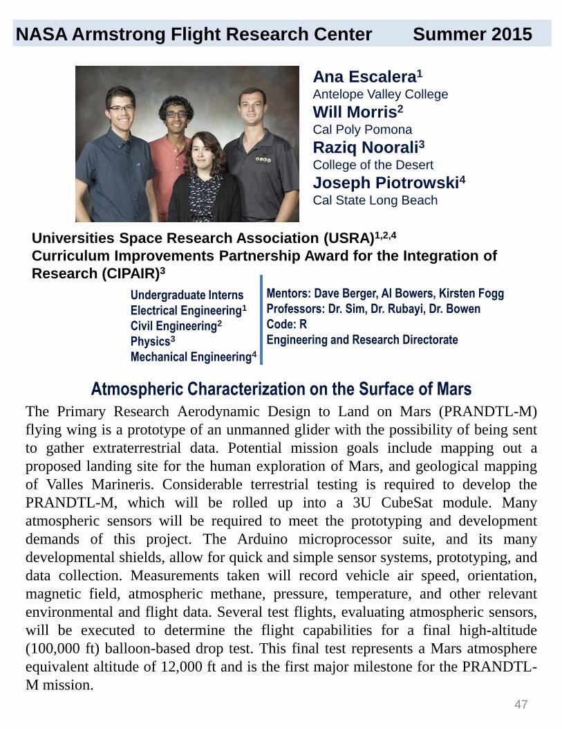
The Primary Research Aerodynamic Design to Land on Mars (PRANDTL-M)
flying wing is a prototype of an unmanned glider with the possibility of being sent
to gather extraterrestrial data. Potential mission goals include mapping out a
proposed landing site for the human exploration of Mars, and geological mapping
of Valles Marineris. Considerable terrestrial testing is required to develop the
PRANDTL-M, which will be rolled up into a 3U CubeSat module. Many
atmospheric sensors will be required to meet the prototyping and development
demands of this project. The Arduino microprocessor suite, and its many
developmental shields, allow for quick and simple sensor systems, prototyping, and
data collection. Measurements taken will record vehicle air speed, orientation,
magnetic field, atmospheric methane, pressure, temperature, and other relevant
environmental and flight data. Several test flights, evaluating atmospheric sensors,
will be executed to determine the flight capabilities for a final high-altitude
(100,000 ft) balloon-based drop test. This final test represents a Mars atmosphere
equivalent altitude of 12,000 ft and is the first major milestone for the PRANDTL-
M mission.
Ana Escalera1
Antelope Valley College
Will Morris2
Cal Poly Pomona
Raziq Noorali3
College of the Desert
Joseph Piotrowski4
Cal State Long Beach
Mentors: Dave Berger, Al Bowers, Kirsten Fogg
Professors: Dr. Sim, Dr. Rubayi, Dr. Bowen
Code: R
Engineering and Research Directorate
Atmospheric Characterization on the Surface of Mars
Universities Space Research Association (USRA)1,2,4
Curriculum Improvements Partnership Award for the Integration of
Research (CIPAIR)3
Undergraduate Interns
Electrical Engineering1
Civil Engineering2
Physics3
Mechanical Engineering4
NASA Armstrong Flight Research Center Summer 2015
47

The project improves upon a risk-averse adaptive control design for flexible
wing aircraft proposed last summer. The design involves partitioning the
actuators of an aircraft so that some are used with an existing nonadaptive
control law, and the rest are utilized by an adaptive control law to jointly
control the vehicle. The partitioning ensures that operation of the
nonadpative law is minimally disturbed, and that the ability to turn off the
adaptive law is preserved. The partitioning also facilitates the problem being
restated as a shifted version of the model reference adaptive control problem
(MRAC). However, a longstanding limitation of MRAC is that it cannot be
applied to nonminimum phase systems. Since aircraft models are frequently
nonminimum phase, the traditional MRAC scheme must be altered to
accommodate them. In the current work a new version of the MRAC scheme
appropriate for nonminimum phase systems is presented. This version only
requires that estimates of the unstable zeros be available for implementation
and still provides reasonably bounded output tracking error. The
performance of the proposed design for both flutter suppression and
command tracking is demonstrated in simulation using various aircraft
models.
Model Reference Adaptive Control for Aircraft with Nonminimum Phase
Zeros
Ph.D. Candidate
Aerospace Engineering
Mentor: Dr. Chan-gi Pak
Code: RS
Aerostructures Branch
Kelley HashemiThe University of Texas at Austin
Jenkins Pre-doctoral
Fellowship Project (JPFP)
NASA Armstrong Flight Research Center Summer 2015
48

The Prandtl-II aircraft is an experimental glider in the Prandtl-D program.
During the summer of 2015, the team performed several data collection
flights with this aircraft and observed the ability of the aircraft to achieve
proverse yaw. Data from these flights was then analyzed in order to obtain
the aerodynamic coefficients necessary to study the flight of the aircraft in
depth. Specifically, finding the yaw moment due to elevon deflection
allowed the team to document the presence of proverse yaw during flight.
Finding most of the coefficients required the use of parameter estimation
(pEst). The team used the pEst program in order to relate the controller input
during a maneuver with the response of the aircraft. The pEst program
analyzes the oscillating motion of the aircraft after a maneuver and then
attempts to recreate the time history by approximating the aerodynamic
coefficients. Through pEst, the data collected during such maneuvers was
used to determine the aerodynamic parameters of the glider.
Analysis of PRANDTL 2 Flight Data
Undergraduate Interns
Mechanical
Engineering1
Aerospace
Engineering2
Mentor: Albion
Bowers, Oscar
Murillo
Code: R
Keenan Albee1
Columbia University
Jonathan Zur2
University of Illinois
Multidisciplinary Aeronautics Research Team Initiative (MARTI)
NASA Armstrong Flight Research Center Summer 2015
49

My project group is working to interpret data from a Fiber Optic Sensing
System (FOSS) measuring strain on the wings of an Unmanned Aerial
Vehicle (UAV), and using this information to modify the wing’s shape. The
UAV being used is the APV 3 aircraft, the wings of which contain over 2000
strain sensors and 44 independently controlled flaps located along the trailing
edges. The objective of this project is to deflect the flaps to redistribute the
lifting load inward toward the fuselage of the aircraft during both, high-G
maneuvers and steady-level flight. This would improve efficiency, gust
mitigation, and the reduction of moment along the wing. With a working
system, the wing could be built with less weight, thereby saving material and
fuel. Code will be written for the flaps to conform to this lift distribution, the
system will be tested in the air in late July, and analysis will be performed to
determine whether the moment along the wing was reduced when the system
was in use. If the moment along the wing was reduced, this would indicate an
effective algorithm, and indicate that controllable flaps can usefully
redistribute lift. With less moment necessary in the wings of an aircraft to
complete a specified maneuver, an equally capable aircraft can be built with
lighter, more deformable wings.
Kira HeadrickHarvard University
Multidisciplinary Aeronautics
Research Team Initiative (MARTI)
Undergraduate Intern
Mechanical Engineering
Mentor: Francisco Pena
Code: RS
Aerostructures
Optimizing Lift in Deformable Wings Using Strain Sensing in Small Aerial
Vehicles
NASA Armstrong Flight Research Center Summer 2015
50

The Fiber Optic Sensing System (FOSS) consists of Fiber Bragg Gratings
that allow for a large quantity of strain sensors to be embedded into a wing at
a low weight cost, enabling structural health monitoring of the entire wing.
The employment of many segmented control surfaces across the entire span
of the wing, however, extends the capabilities of FOSS into the realm of
actively shaping the lift distribution. By shifting the lift distribution inboard,
it is possible to reduce the bending moment on the wingbox, while
maintaining a constant total lift. The feedback control system integrating
FOSS data with the actuation of the segmented control surfaces is currently
being developed, with multiple control schemes being investigated. In
addition to targeting a reference root strain, a control system targeting tip
deflection, and eventually tailoring the entire lift distribution, will be
developed and flown for evaluation on the small, unmanned APV-3. The
control systems will be investigated for the capability to automatically
redistribute lift and reduce structural loads during maneuvers with increased
wing loadings, as well as for gust alleviation.
Clement LiPrinceton University
Multidisciplinary Aeronautics
Research Team Initiative (MARTI)
Undergraduate Intern
Mechanical and Aerospace
Engineering
Mentor: Frank Pena
Code: RS
Aero Structures Branch
Development and Evaluation of Feedback Control Systems Using
Segmented Control Surfaces and Fiber Optic Sensing System
NASA Armstrong Flight Research Center Summer 2015
51

Flight testing is an integral part of the National Aeronautics and Space
Administration (NASA) Armstrong Flight Research Center operations and
continues to grow tremendously with a variety of upcoming projects. The
Primary Research AerodyNamic Design To Lower Drag (PRANDTL-D)
seeks to overcome adverse yaw effects by using a non-linear aerodynamic
twist. Proverse yaw, the tendency for an aircraft to roll and yaw in the same
direction, is possible with the PRANDTL-D distinctive wing shape, lift
distribution, and lack of a vertical tail. A PRANDTL-D type vehicle will
significantly reduce drag and weight from the aircraft, therefore making
worldwide green aviation goals attainable. In order to demonstrate these
effects, accurate data must be recorded by performing roll and pitch doublet
maneuvers on the aircraft. Instrumentation on the aircraft gathered data of
interest during scheduled flights. Individuals within the flight-testing group
were assigned roles to oversee flight procedures, aircraft testing, and data
management. Briefings were conducted in order to maintain proper
communication and ensure the airworthiness of the aircraft. With the data
collected from each scheduled flight and with further research in this ground
breaking discovery, we hope to be able to influence the future of aviation..
Undergraduate
Interns
Mechanical
Engineering
Mentor: Oscar Murillo
& Al Bowers
Code: R
Engineering and
Research Directorate
Prandtl-D Flight Testing and Operations
Kassidy McLaughlin1
California State University at Long Beach
Alexandra Ocasio2
University of Puerto Rico at Mayaguez
NASA Armstrong Flight Research Center Summer 2015
Universities Space Research Association (USRA)1
Multidisciplinary Aeronautics Research Team Initiative (MARTI)2
52
Enhancing the wing shape of an aircraft provides essential flight
characteristics to distribute the aerodynamic load more efficiently. Currently,
however, it has been challenging to monitor the real-time shape of the wing
during flight. The NASA Armstrong Flight Research Center developed a
fiber-optic sensing system (FOSS) that is lightweight and capable of making a
multitude of distributed strain measurements on aerospace structures in real
time. The aircraft being used for this project is an Autonomous Piloted
Vehicle 3 (APV3) with approximately 2000 fiber-optic strain sensors along
the wingspan, and 44 segmented control surfaces along the trailing edge. The
influences of the FOSS strain measurements can be used to determine the
deformation of the wing during flight. Ultimately, when the shape is
determined, APV3 will be able to control the trailing edge positions and thus
redistribute the load to a more favorable configuration, reducing the bending
stresses along the wing and increasing the performance of the aircraft. In
addition, monitoring real-time shape would allow a reduction of structure
support in the aircraft, minimizing weight and therefore the amount of fuel
carried. The research being tested on APV3 is a step toward improving the
future of the environment and of efficient flight.
Christopher TrumbullUtah State University
Multidisciplinary Aeronautics
Research Team Initiative (MARTI)
Professional Intern
Mechanical Engineering with
an emphasis in Aerospace
Engineering
Mentor: Francisco Peña
Code: RS
Aerostructures
Controlling Wing Deformation In-flight Using Adaptive Control Surfaces
Along Trailing Edge
NASA Armstrong Flight Research Center Summer 2015
53
Many species of birds travel in distinctive “V” formations. Steven Portugal
of the Royal Veterinary College has investigated flight formations of the Ibis
species. His data can be correlated to the expected bell-shaped lift
distribution of the PRANDTL experimental glider currently being
researched at the NASA Armstrong Flight Research Center. The raw data
collected by Portugal’s observation of Ibis flight demonstrates an
upwash/downwash curve strikingly similar to that of the PRANDTL glider.
This research investigates formation flight of Ibis in order to find a
correlation between the formation structure and the lift distributions across
the birds themselves. The team used Portugal’s GPS (global positioning
system) coordinates of the flying birds to plot relationship data of the birds
in stable “V” formation using MATLAB®. In this way the team was able to
use the PRANDTL upwash curve to find an aerodynamic efficiency curve
that can be matched to Ibis flight..
Undergraduate Intern
Aerospace Engineering
Mentor: Oscar Murillo
Code: R
Engineering and Research
Directorate
Analysis of Steven Portugal’s Ibis Formation Flight Data and Application
to PRANDTL Aircraft
Kaixi WangUniversity of Texas at Austin
Multidisciplinary Aerospace
Research Team Initiative (MARTI)
NASA Armstrong Flight Research Center Summer 2015
54

The Leading Edge Asynchronous Propellers Technology (LEAPTech)
program is an experimental project that looks to create hybrid and hybrid-
electric aircraft propulsion. By advancing the field of alternative fuel
technology like electric and hybrid-electric propulsion for flight the project
can contribute to global clean-air and green technology initiatives while also
achieving project goals of reduced emissions, noise reduction, and increased
efficiency. The goal of this project is to investigate the advantages of using
Silicon Carbide Technology over standard silicon based technology in the
design of a more efficient AC/DC power convertor. With experimentation of
smaller base components the project looks to discover and record the upper
and lower operating limits as well as the most efficient operating ranges
under a variety of testing variables to diagnose and record input/output
variations. The project will apply our findings in the diagnosis of
input/output variations of larger complex components which may be used in
the creation of a turbo generator AC/DC power convertor. By implementing
superior silicon carbide components we hope to increase efficiency and
performance of the LEAPTech hybrid-electric propulsion system and
project, while meeting project goals and supporting the NASA mission
statement.
Undergraduate Intern
Mechanical Engineering
Mentor: Yohan Lin
Code: RT
Vehicle Test and Integration
Design of an AC/DC Convertor Utilizing Silicon Carbide Technology
Troy T. KuhnsVictor Valley College
NSF Centers of Research
Excellence in Science and
Technology (CREST)
NASA Armstrong Flight Research Center Summer 2015
55
The Leading Edge Asynchronous Propeller Technology (LEAPTech) is an
experimental production that aims to power the aircraft of tomorrow through
electric and hybrid electric means. Alternative power consumption
technologies, like electric and hybrid electric flight, contribute to the global
push in green technologies that significantly reduce fuel/energy consumption
and unclean emissions. The leading objective of this project is to produce
aerodynamic and power architecture data from the test runs, and develop a
procedure that analyzes and processes the data in an interpretable form to be
disseminated to the various stakeholders, including NASA Langley, for
design considerations in developing the next electric X-plane. Data will first
be collected from the LEAPTech test-runs and accessed through the Omega
Data Environment (ODE). The data will then be processed through
MATLAB and run through specific scripts that output the data in more
manageable graphs and formats. Certain types of data will also be assembled
to each user’s specific needs and formats. An established process for
communicating and disseminating essential data will be established and set
the framework for a future position that is in charge of consolidating and
disseminating data in the appropriate format to NASA Langley and other
appropriate stockholders.
Undergraduate Intern
Computer Engineering
Mentor: Kurt V. Papathakis
Code: RT
Vehicle Integration and Test
LEAPTech Data Mining and Dissemination
Timothy NuñezVictor Valley College
NSF Centers of Research
Excellence in Science and
Technology (CREST)
NASA Armstrong Flight Research Center Summer 2015
56

On December 1, 1984, the Armstrong Flight Research Center (AFRC)
assisted the Federal Aviation Agency (FAA) in its quest to improve aircraft
crash safety through the minimization of post-impact fire by conducting a
full scale crash demonstration, termed as the Controlled Impact
Demonstration (CID). The CID resulted in a shocking fireball. Questions
still remain unanswered from this event, among them, ‘Was this a success or
a failure?’ ‘Was this a test or an experiment?’ In an effort to preserve the
work performed at, and the lessons learned by AFRC, my project is to
produce an historical manuscript for the CID. A previously written
manuscript on the CID was rendered incomplete. To provide a complete
historical analysis, I seek to answer the questions begged by the CID, as well
as highlight AFRC’s major contributions to the CID - the Remotely Piloted
Vehicle (RPV) development and the Boeing 720 systems integration. More
specifically, my project consists of conducting and integrating interviews
with CID engineers in to the manuscript, researching archived CID
documentation, evaluating the validity of previous sources, updating the
previous source information with accurate and archived documentation, and
finally, editing, rewriting, and restructuring the manuscript. The manuscript
will be completed the summer of 2016.
Undergraduate Intern
Mathematics and
Philosophy
Mentor: Christian Gelzer
Code: T
Strategic Communications
A Historical Manuscript of the Controlled Impact Demonstration
Christy AilmanAzusa Pacific University
Universities Space Research
Association (USRA)
NASA Armstrong Flight Research Center Summer 2015
57

NASA has a long history of testing, retesting, and proving its technologies before trusting
them in critical mission applications. NASA is still at the cutting edge of engineering, design,
research, and innovation. However, light is not always shed on these brilliant inventions and
some radical innovations never make it to the public sector. In order to make these advanced
technologies readily available for the public use, NASA assembled the Technology Transfer
team. The mission of the Technology Transfer Office at the NASA Armstrong Flight
Research Center is to bridge the gap between NASA-engineered technology and
commercialization of these technologies in the open market, ultimately granting citizens of
the United States access to these inventions. I and my teammate Yasmin Alkusari have been
assigned the transfer and commercialization of the Prandtl project. Together we are utilizing
our engineering and business backgrounds to come up with unique and creative ways of
reapplying the Prandtl project. Essentially, we analyze other potential applications that
include wind turbines, animal prosthetics, propellers, automotive spoiler design, new aircraft
design, and retrofit solutions. Our end goal is to advance the development of the Prandtl
project through various venues that include gaining exposure to multiple subject matter
experts on the technology; being involved in current Prandtl-based projects to deepen our
understanding of the technology; perform strength, weakness, opportunity, and threat
(SWOT) analysis on the project; conduct market studies on new applications; and apply in-
depth industry research that provides technical and business possibilities. As well, our
objective is to provide a roadmap for commercialization and potential design prototypes
through researching and analyzing key business dimensions for primary identified market
applications. By using secondary research and inventor interviews and project exposure, we
are building an implementable plan with relevant stakeholder contacts and potential
commercial distribution channels or strategic partners.
Technology Transfer for Improved Aircraft Design (Prandtl Project)
William AlfanoRutgers, The State University of New Jersey
Universities Space Research
Association (USRA)
Undergraduate Intern
Major I: Electrical & Computer
Engineering
Major II: Finance
Mentor: Laura Fobel
Code: RO
Research Operations
NASA Armstrong Flight Research Center Summer 2015
58

One of the National Aeronautic and Space Administration (NASA) advancing missions is
to develop innovative technologies and disperse them into industry applications for
commercial use. By licensing and commercializing innovative technologies discovered,
NASA is able to disseminate novel technologies to the public domain. This dissemination
results in an increased quality of life, a stronger economy, and the utilization of high-tech
devices on a daily basis. The Technology Transfer Office adds significant value to NASA
by facilitating the patenting process for the benefit of NASA employees. Working as an
engineering consultant alongside William Alfano, my business teammate, we apply our
diverse backgrounds to discover unique and innovative commercial applications and
opportunities for the transfer of NASA technologies to industry. Working as a team, we
look for a wide range of possibilities that these technologies could be used for other than
the intended purpose. Our goal is to commercialize government technologies utilizing
market studies to determine where new, more efficient technologies can advance or
replace existing technologies currently on the market. Engineering and business skills are
combined to analyze strengths, weaknesses, opportunities, and threats on NASA
innovations. Our objective is to conduct market studies, study relevant patents, and
examine the current and new technology in order to develop a commercialization plan.
The Technology Transfer Office uses this plan to pursue product licensing. Primary
research will be conducted by interviewing inventors to fully understand the innovation
and its functions. By using inventor interviews along with secondary research, we can
design an equipped plan with pertinent stakeholder contacts in addition to potential
commercial distribution pathways or strategic partners. The current technology our team
is assessing is improved aircraft design.
Yasmin Alkusari The University of Texas at San Antonio
Universities Space Research
Association (USRA)
Undergraduate Intern
Biomedical Engineering
Emphasis: Biomechanics,
Imaging
Mentor: Laura Fobel
Code: RO
Research Operations
Commercialization of Intellectual Property through Technology Transfer
NASA Armstrong Flight Research Center Summer 2015

The Primary Research Aerodynamic Design to Land on Mars (PRANDTL-M) is
a small glider that will potentially be the first airplane in Mars’ atmosphere.
PRANDTL-M’s mission is to produce high-definition ground mapping and an
atmospheric data collection system using a small, custom, lightweight
microcontroller platform. The 3DR Pixhawk autopilot open source platform
serves as the terrestrial control solution using GPS and standard methods. The
Pixhawk will be modified in hardware and software to only include the most
essential features, to avoid any unnecessary weight, and improve processor
efficiency. The airspeed indicator, altimeter, gyroscope, GPS, compass, optical
flow sensor, and accelerometer will gather data to assist in the navigation and
control of PRANDTL-M. Pixhawk can be programmed and controlled using
QGroundControl software, where the gain values will be tuned to provide for a
stable flight-control solution. In addition, X-Plane, a simulation program, is used
to run a Hardware-in-the-Loop (HIL) in parallel with QGroundControl to test
the inputs and outputs of the system, reducing development time and allowing
for first-order testing of new code. PRANDTL-M will be navigated through
waypoints initially set in QGroundControl.
Sipanah Arutyunyan1
Orlando Mielke2
Hussein Nasr3
Bogdan Pugach4
University Space Research
Association (USRA)
Mentors: Dave Berger, Al Bowers, Kirsten Fogg
Professors: Dr. Sim, Dr. Rubayi, Dr. Bowen
Code: R
Research and Engineering Directorate
Autopilot System for PRANDTL-M Aircraft
Undergraduate Interns
Aerospace Engineering1,2,3,
Electrical Engineering4
NASA Armstrong Flight Research Center Summer 2015
Cal Poly Pomona1,2,3,4
60

An aircraft in a cooperative flight formation can utilize the upwash of wake
vortices generated by a lead aircraft to reduce drag and increase fuel
efficiency. A wake vortex encounter while flying near the wake could be
dangerous and wake vortices are generally not visible. Automated
Cooperative Trajectory (ACT) control algorithms are being developed and a
Display for Awareness of the Vortex Estimation (DAVE) is necessary for the
pilot to monitor the automated system and display the estimated position
information relative to the vortex. Display development will be
accomplished on an existing head-down display (HDD) in the SubsoniC
Research Aircraft Testbed (SCRAT) piloted simulation. Objects within the
display will be driven by the control laws to monitor relative position to
desired location and vortex proximity. In order to develop wake displays for
the pilot, prototypes will be developed within the engineering team and
discussed with pilots for feedback. Several candidate displays will be
developed and implemented in the SCRAT simulator during which pilot
evaluations will be collected. Results from this investigation will lead to
recommendations for a final display.
Display Development for Awareness of Vortex Estimation (DAVE) for
Automated Cooperative Trajectories (ACT)
Mentor: Joe Pahle
Code: RC
Dynamics and Controls
Christopher BryanCal State University, San Bernardino
Universities Space Research
Association (USRA)
NASA Armstrong Flight Research Center Summer 2015
Undergraduate Intern
Physics
61
The Mars Airplane Live event is an event to take place in October at the
Aero Institute. Initially, the event needs to be accepted via proposal by the
American Institute of Aeronautics and Astronautics (AIAA) for funding. The
National Aeronautics and Space Administration (NASA) must also accept
the proposition via tactical management board; with both organizations
accepting the proposal, the event will be allowed to take place. The main
idea is to create an event to attract the younger audience, as well as be a
virtual way to obtain information. The event will star the Primary Research
Aerodynamic Design To Land on Mars (PRANDTL-M), or The Mars
Airplane, and will show the public what the concept is, what the purpose will
be, and how they will obtain their expected outcome. The event will be
livestreamed in order to appeal to the youth, as well as complete the task of
creating a virtual medium of information. The event will start with Al
Bowers describing the basics of the PRANDTL-M, followed by two interns
who will go more in-depth with what they have been doing for the
advancement of this project. The event will be advertised via email and
social media, specifically targeting university students as well as young
professionals all over the country. The event’s goal is to provide a high
energy, entertaining, interactive event that encourages the youth to join a
prestigious organization that appeals to their love of all things aero.
Undergraduate Intern
Business Management/
Entrepreneurship
Mentor: Peggy Hayes
Code: XP
Projects
The Mars Airplane Live Event
Benjamin CobleighUniversity of Arizona
Universities Space Research
Association (USRA)
NASA Armstrong Flight Research Center Summer 2015
62

The Office of Education at NASA works in unity with various centers and
offices to provide learners with valuable educational experiences. One goal
of NASA’s education program is to provide a platform for people of all ages
to spark an interest in the science, technology, engineering, and mathematics
fields. To provide a meaningful summer internship experience, the student
coordinator is responsible for several essential duties that contribute to the
functionality of the program. Some of these tasks include ensuring visit
requests are completed properly, assisting in arrival orientation, and
coordinating various tours of our center. Lunchtime brown bag seminars,
presented by NASA employees on a variety of topics relevant to Armstrong
Flight Research Center, are coordinated by the student coordinator. Briefings
are hosted to provide guidance on topics including Scientific and Technical
Information and Export Control. Students’ preliminary plans, abstracts,
professional posters, and exit presentations are coordinated, approved, and
produced through the assistance of the student coordinator. Another aspect of
the student coordinator’s job is to evaluate the student intern program and
report on student statistics. This includes producing relevant quantitative and
illustrative documentation to be used in MUREP White House Reports,
OEPM, Monthly MUREP Agency calls, NIFS biweekly calls, and Center
Coordinator calls.
Undergraduate Intern
Business Human Resources
Mentor: Rebecca Flick
Code: K
Office of Education
Coordinating the NASA Armstrong Internship Program
Rheanna CoweeSan Diego State University
Universities Space Research
Association (USRA)
NASA Armstrong Flight Research Center Summer 2015
63
NASA Armstrong Flight Research Center Summer 2015
Routine access by unmanned aircraft systems (UAS) in the National Airspace
System (NAS) requires closure of a number of technology gaps. The purpose of
the UAS in the NAS project is to help close these gaps by integrating multiple
system components in an operationally relevant test environment. The NASA
Armstrong Flight Research Center has teamed with the NASA Ames Research
Center, the NASA Langley Research Center, the NASA Glenn Research Center,
and several industry partners to integrate and test the viability of data
communication systems, sense-and-avoid programs, and human systems
integration technologies and procedures for autonomous aircraft. Once put into
situations that represent real-world scenarios that UAS pilots would encounter in
the NAS, these systems are designed to tell a pilot when a possible threat is
approaching, and suggest a maneuver that will prevent a mid-air collision or other
catastrophe that may endanger others in the air or on the ground below. NASA is
also using live data to validate results, such as sensor performance and reliability,
state data uncertainty, and other results, which were collected in previous tests
conducted with simulations. The systems are also being tested to examine how
they will react when placed in situations in which there are unpredictable factors,
such as wind. Once testing is completed, the results gathered will be used to help
develop the Minimum Operational Performance Standards (MOPS). These MOPS
will help develop FAA technical standards and regulatory changes to allow UAS
to routinely fly in the NAS.
John FreudingerCalifornia State University, Long Beach
Universities Space Research
Association (USRA)
Undergraduate Intern
Computer Engineering
Mentor: Sam Kim
Code: RE
Systems Engineering and
Integration
Unmanned Aircraft Systems Integration in the National Airspace System
64

The use of an analog-to-digital (ADC) converter in systems that require the real-
time response found in aircraft flight controls must be accurate and reliable to
ensure safety. The ADCs found in the autopilot currently in use by the Prandtl-D
aircraft are part of a critical flight control system that includes elevons, alpha
vanes, and beta vanes. As these components change their angular position a
corresponding change in voltage occurs. This voltage is continuous in time and
must be translated into digital binary code for interpretation by the flight control
computer (FCC). The performance of an ADC is predominantly dependent upon its
resolution and speed. The autopilot currently uses a 16-bit Semtech SX8724C ADC
that is working at half its maximum resolution, effectively rendering the precision
of the ADC over a 2.5V range to 76.29µV from a theoretical 39.67µV maximum
resolution. The objectives are to increase the resolution of the ADC to its maximum
16-bit capacity and improve system robustness through the design of a printed
circuit board compatible with the current autopilot platform. It is important to
upgrade the resolution of the ADCs with minimal disturbance to other flight
systems; in order to accomplish this all final changes will be made using software.
The approach is to devise a method of calibrating the ADCs while evaluating
important parameters that include noise and effective resolution. Once a reliable
testing and calibration method has been developed for the ADCs the corresponding
changes will be made to the flight control software and tested before flight. All
methods and procedures will be stored in a database to ensure sustainability.
Undergraduate Intern
Electrical Engineering
Mentor: Ben J. Pearson
Code: ME
Simulation Engineering
Hardware
Improvement and Testing of Analog to Digital Converters
Pablo J. GonzalezFlorida International University
University Space and Research
Association (USRA)
NASA Armstrong Flight Research Center Summer 2015
65

Commercial solutions for controlling and collecting flight data from research aircraft
can be relatively expensive, rarely come with source code or provision for hardware
or software customization, and are typically designed with vehicle control in mind
and data collection as an afterthought. This typically leaves research vehicles in need
of a secondary data collection system, or “data cube.” One solution to the high-cost,
proprietary, control-focused commercial solutions is a flight computer, nicknamed
“Goldy” and built by the University of Minnesota. Goldy is an all-inclusive flight
control system (FCS) with data acquisition, as well as a work in progress.
The Goldy FCS came to the NASA Armstrong Flight Research Center with software
problems involving memory leaks and data throughput from peripheral sensors –
specifically those on the I2C bus. The I2C data throughput problem required both
hardware and software solutions in the form of a low-impedance circuit, a
reprogrammed driver for the analog-to-digital converters (ADC) and modifications
to the data collection functions. The embedded Configurable operating system
(eCos) buffers data files stored in volatile memory, causing unlinked files to remain
in memory until a hard reset occurs. The solution to this problem required un-
mounting and re-mounting the file system as a part of the data logging software
routine. The Goldy FCS (serial #002) with updated software has been successfully
flown on the PRANDTL-2 aircraft and has collected data from almost 30 flights to
date. Work still in progress includes adding support for storing data in non-volatile
memory and for ADCs that provide for many more (on the order of 50) analog input
channels.
Graduate Student Intern
Mechanical & Aerospace
Engineering
Mentors: Red Jensen, Oscar
Murillo, Al Bowers
Code: R
Engineering and Research
Directorate
Small, Uninhabited Aerial Systems (sUAS)
E. Etan HalbergUniversity of California, Davis
Universities Space Research
Association (USRA)
NASA Armstrong Flight Research Center Summer 2015
66

One of the unmanned aerial vehicles (UAVs) being worked on at the
National Aeronautics and Space Administration (NASA) Armstrong Flight
Research Center is the Towed Glider, which is carrying a rocket payload as a
less expensive way to get satellites and other objects into orbit. To release
the payload, there are different maneuvers being considered that benefit from
additional thrust. An onboard hybrid rocket is going to be used to provide
this additional thrust. However, to control the rocket, a motor controller is
needed that would communicate between the rocket and the ground control
station (GCS) via the Piccollo Autopilot . We were able to design the motor
controller using the Code Composer Studio (CCS) for software development
and Altium Designer for circuit/PCB design. The motor controller was
designed using the Delfino F28335 control card microcontroller. The motor
controller was lab-tested and found to interface smoothly between the GCS
and the hybrid rocket.
Graduate Intern
Aeronautics &
Astronautics Engineering
Mentor: Otto C. Schnarr
Code: RD
Sensors and Systems
Development Engineer
Designing a Motor Controller for the Hybrid Rocket of the Towed-Glider
Waqqas H. KhanStanford University
Universities Space Research
Association (USRA)
NASA Armstrong Flight Research Center Summer 2015
67
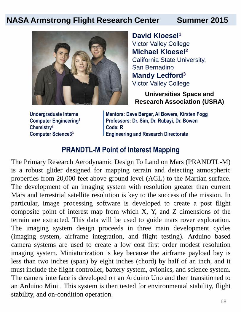
The Primary Research Aerodynamic Design To Land on Mars (PRANDTL-M)
is a robust glider designed for mapping terrain and detecting atmospheric
properties from 20,000 feet above ground level (AGL) to the Martian surface.
The development of an imaging system with resolution greater than current
Mars and terrestrial satellite resolution is key to the success of the mission. In
particular, image processing software is developed to create a post flight
composite point of interest map from which X, Y, and Z dimensions of the
terrain are extracted. This data will be used to guide mars rover exploration.
The imaging system design proceeds in three main development cycles
(imaging system, airframe integration, and flight testing). Arduino based
camera systems are used to create a low cost first order modest resolution
imaging system. Miniaturization is key because the airframe payload bay is
less than two inches (span) by eight inches (chord) by half of an inch, and it
must include the flight controller, battery system, avionics, and science system.
The camera interface is developed on an Arduino Uno and then transitioned to
an Arduino Mini . This system is then tested for environmental stability, flight
stability, and on-condition operation.
PRANDTL-M Point of Interest Mapping
David Kloesel1
Victor Valley College
Michael Kloesel2
California State University,
San Bernadino
Mandy Ledford3
Victor Valley College
Universities Space and
Research Association (USRA)
Undergraduate Interns
Computer Engineering1
Chemistry2
Computer Science33
Mentors: Dave Berger, Al Bowers, Kirsten Fogg
Professors: Dr. Sim, Dr. Rubayi, Dr. Bowen
Code: R
Engineering and Research Directorate
NASA Armstrong Flight Research Center Summer 2015
68
The purpose of the Primary Research Aerodynamic Design To Land on Mars
(PRANDTL-M) project is to prove that the flying wing design will work for a
mission to Mars, to provide better image mapping than satellites, and to collect
data for atmospheric characterization. One of the most crucial is environmental
testing. The equipment will be placed in environmental chambers which will
simulate Martian conditions, and performance parameters, such as power draw
and sampling rates, will be monitored. There will also be a series of flight tests
to determine the flight characteristics and stability of the flying wing design.
First, there will be indoor tests, in which several prototype flying wings will be
thrown by hand or launched using a rubber band system to determine the
stability of each design and calculate the lift to drag ratio. Next, the prototypes
will be loaded with a simple sensing package (an accelerometer, gyroscope,
and barometer) and will be launched from a building roof. This launch will
yield data on the aircraft stability and flight characteristics such as roll, pitch,
and yaw rates. Finally, the full flight system (autopilot, camera, sensing, and
mapping) will be tested by DROID captive carry tests. The DROID aircraft
will carry the glider to approximately 1,000 feet , where it will be released and
allowed to glide back to the surface. This will verify the integration of the
systems with the airframe and prove whether the design is a good concept for a
Mars mission.
Testing of PRANDTL-M
Undergraduate Intern
Aerospace
Engineering
Mentors: Dave Berger, Al Bowers,
Kirsten Fogg
Code: R
Engineering and Research
Directorate
Heather LaffoonCalifornia State University, Long Beach
Universities Space Research
Association (USRA)
NASA Armstrong Flight Research Center Summer 2015
69

SubsoniC Research Aircraft Testbed (SCRAT) is a modified G-III research
airplane for NASA Armstrong. SCRAT is currently modified to test Adaptive
Compliant Trailing Edge (ACTE). ACTE is two modified flaps that have
transition surfaces on each side of the flaps; ACTE creates a flap with a
continuous surface. ACTE may allow for a 3-10 percent cruise drag
reduction, 20 percent wing weight reduction, 4-6 dB noise reduction during
approach and landing, structural load alleviation, and increased control
surface effectiveness. This summer I mainly focused on creating or assisting
modifications to SCRAT. I environmentally tested many new aircraft testing
components including HD Cameras, Heat Controllers, and HDMI Recorders.
I also created the environmental test plan for SCRAT. I designed a wiring
pass through the pressurized AFT bulkhead for the HDMI Recorders, HD
Cameras, Hydraulic Pressure Transducer, Fuel Flow Meters, and any future
wiring. I learned about the operation and utility of the laser tracker
measurement system. I was a part of the planning team of a joint acoustics
test with Langley and Armstrong personnel on the lakebed. I assisted any
member on the SCRAT or ACTE as needed for the remainder of my summer
internship.
Undergraduate Intern
Mechanical Engineering
Mentor: John Ruhf
Code: OE
Operations Engineering
Assisting and Completing Modifications on SCRAT
Harrison PauerUniversity of California, Irvine
Universities Space Research
Association (USRA)
NASA Armstrong Flight Research Center Summer 2015
70

A document file naming schema is a standardized agreement that applies to all
document types within an organization. In a database, each item is given an
index, which allows users to precisely locate a piece of information. In the
past, a unique naming convention was created specifically for each project at
the National Aeronautics and Space Administration (NASA) Armstrong Flight
Research Center and lacked unified regulation. This problem has led to data
loss and wasted resources at the center. My summer project is to design and
implement a unified naming standard for project data and then identify areas
within test data that could use a similar process. This system will also contain
metadata attributes that will assist users in identifying legacy data. The data
models provided as well as past naming conventions serve as a primary
baseline for my project. In order to compensate for different databases that
NASA uses, this program will transfer the middleware portal from the
Stratospheric Observatory For Infrared Astronomy (SOFIA) to a generic
version, applying additional features that will aid in search capabilities. A
primary focus is to identify all of the possible data types within project data to
ensure that this process cannot be avoided by default. My project could save
significant time and resources at the center and increase research efficiency.
Once implemented at the entire center, my program will assure data security
for present and future researchers.
Developing a Document Naming Schema for Armstrong Flight Research
Center
Karter RohrerCalifornia Polytechnic State University
Undergraduate Intern
Computer Information
Systems
Mentor: Ronald Ray
Code: RO
Knowledge Management
Universities Space Research
Association (USRA)
NASA Armstrong Flight Research Center Summer 2015
71
The Prandtl airplanes and their wingtip designs have gained attention for their
ability to overcome adverse yaw and turn it into proverse yaw, all without a
vertical tail.
Two new projects have emerged that are building on the successes of
previous Prandtl research projects. The Primary Research Aerodynamic
Design To Land on Mars (Prandtl-M) is a small, 24-inch wingspan, glider that
will be released from a high altitude in the Martian atmosphere and will send
back to Earth high resolution images.
The Prandtl-3 is a larger scale version of the Prandtl-2. At 24 feet in
wingspan, this larger size will allow for fiber optic strain sensing, as well as
pressure taps in the wing to detect changes in the pressure field around the
lifting surfaces.
My objective is to provide mechanical design work for both of these projects
and project teams to ensure all is on track for a timely completion. Through
meetings with the project teams and my mentors, the requirements for a
certain 3D model are specified and allow for less remodeling as the projects
move forward.
Prandtl-M will provide a better look at the surface of Mars and will allow
more informed decisions to be made about future Mars missions, manned and
unmanned. Prandtl-3 will allow for a more thorough, data-supported
understanding of the aerodynamics of the unique wing shape.
Undergraduate Intern
Computer Engineering
Mentor: Robert “Red” Jensen
Code: R
Research and Engineering
Mechanical Design: PRANDTL-M and PRANDTL-3
Victor Gabriel RuizCalifornia Polytechnic State University,
Pomona
Universities Space Research
Association (USRA)
NASA Armstrong Flight Research Center Summer 2015
72

NASA’s strategic objective on education is to “Advance the Nation’s
Science, Technology, Engineering and Mathematics (STEM) education and
workforce pipeline by working collaboratively with other agencies to engage
students, teachers, and faculty in NASA’s missions and unique assets.”
NASA Armstrong Flight Research Center’s Office of Education is
committed to this objective by delivering effective STEM education that
provides opportunities for participatory and experiential learning activities in
formal and informal settings, to connect learners to NASA-unique resources.
AFRC’s Office of Education provides many STEM education opportunities
for learners of all ages throughout the summer, which include Thursday
Nights on the Square, as well as various robotics workshops throughout the
Antelope Valley. Educational content is provided to local robotics workshops
through guest speakers and hands-on activities. In partnership with the
AERO Institute, AFRC’s Office of Education conducts multiple robotics
workshops utilizing LEGO Mindstorms. The summer robotic workshops
vary from teaching students and educators how to code, to teaching them
how to design and build robots to play a game. NASA Education programs,
projects, and activities are designed to align with NASA missions, with an
emphasis on NASA’s content, people, and facilities and are directly linked to
inspiring the next generation of explorers and innovators.
Undergraduate Intern
Electrical Engineering
Mentor: Kirsten Fogg
Code: K
Office of Education
NASA’s Educational Workshops
Ivan SalazarUniversity of California, San Diego
University Space Research
Association (USRA)
NASA Armstrong Flight Research Center Summer 2015
73
A major goal of NASA’s Aeronautics Research Mission Directorate is to
save fuel and reduce harmful emissions. Migrating birds fly in a “V”
formation to save each trailing bird large amounts of energy. Aircraft have
also shown large fuel savings (up to 18 percent) by flying in formation. It is
difficult, however, for pilots to fly in formation for long flights since a
trailing plane must stay in a very narrow “sweet spot” in the lead plane’s
wake to derive fuel savings.
The main task involved developing model and control laws for a Gulfstream
G-III airplane to act as a virtual lead plane capable of executing altitude,
heading, and speed changes. It will be used in simulations and flight to test
wake surfing control laws and algorithms, and will aid in testing the viability
of autonomous wake surfing in commercial and military applications.
Other tasks included performing aerodynamic analysis of, and writing
control laws for, a novel aircraft configuration for wake surfing using solar-
powered High Altitude Long Endurance aircraft to see if it would be viable
for use in long-term applications, such as in communications and
atmospheric sensing. A wing-tip vortex wake estimation algorithm that was
originally designed for a glider was also modified for a G-III.
Performance Analysis and Control Law Development for Autonomous
Wake Surfing Tests and Simulations
Undergraduate Intern
Mechanical Engineering
Mentor: Curtis Hanson
Code: RC
Dynamics and Controls Branch
Rachel SaltzmanCalifornia State University, Fresno
Universities Space and Research
Association (USRA)
NASA Armstrong Flight Research Center Summer 2015
74

The Primary Research Aerodynamic Design To Land on Mars (PRANDTL-M) is a
high-altitude, low-density glider designed for mapping terrain and detecting methane
deposits at 20,000 ft above the Martian surface. Capable of autonomous navigation,
the objective of the PRANDTL-M will support the National Aeronautics and Space
Administration’s (NASA’s) overall objective of human exploration on Mars. The
PRANDTL-M airframe must be durable enough to withstand the harsh environmental
conditions present on Mars, but also be aerodynamic enough to maintain flight.
Environmental testing will subject the airframe to temperatures and pressures beyond
those present on Mars to test functional limits. The data collected will be used to
analyze efficiency and durability. Several parameters must be considered, which
include the center of gravity (CG) of both the fuselage and wing, weight of airframe,
and aerodynamic shape. Since weight opposes lift and would negatively affect the
distance the aircraft would fly, foam was chosen as the lightest material for the
fuselage. Drag will be reduced by designing a fuselage with the most streamlined
surfaces and configuration with an internal components bay to mitigate turbulence.
Using Creo Element Pro and SolidWorks, a design will be sketched and modeled
where a 3D printer will construct the final fuselage for precision. The final design will
be flight-tested, both indoors and outdoors, for aerodynamic control, lift produced,
and distance covered.
Undergraduate Interns
Aerospace Engineering1
Biomedical Engineering2
Mentors: Dave Berger, Kirsten Fogg, Al
Bowers, Khalid Rubayi, Jason Bowen,
Alec Sim
Code: R
Research and Engineering Directorate
Airframe Integration for the Primary Research Aerodynamic Design to
Land on Mars (PRANDTL-M)
Joshua Tanon1
University of Michigan
Universities Space Research
Association (USRA)
Eduardo Uribe-Saldana2
Antelope Valley College
NASA Armstrong Flight Research Center Summer 2015
75

Working in the Photo and Video Labs at NASA
Universities Space Research
Association (USRA)
Undergraduate Intern
Film Studies
Mentor: James Ross
Code: MI
Information Systems
Benjamin WrightCalifornia State University of Long Beach
NASA Armstrong Flight Research Center Summer 2015
While here at NASA I am spending five weeks in the Photo Lab and five
weeks in the Video Lab. While in the Photo Lab I was tasked with logging
descriptions and dates of every photo taken at NASA since 1948. I only made
it to about 1960 until my first five weeks were up. Along with logging
photographs I also shadowed the professional photographers as they did their
jobs.
After my first five weeks were up, I transferred to the Video Lab where I will
conclude my internship here at NASA. My duties in the Video Lab have been
to film, control, and run audio on the “Brown Bag” lecture sessions, as well
as any other presentations made at NASA that require a video made of the
presentation. Another notable project I am working on in the Video Lab is
filming the test flights of the Prandtl-D flying wing. After all of the filming is
complete, I will edit all of the footage and create one cohesive film. This film
will be presented at the end of the session to the interns who worked on the
Prandtl-D project.
This internship is helping me learn what being a professional photographer
and videographer at NASA truly means.
76
Future hybrid turbo-electric airplanes will require close coupling between
the mechanical thermodynamic turbine system and the electrical
generator control system. The investigation of the control system fuel
start ramps of a small 10kW micro-turbine provides a stepping stone to
understanding larger kW turbo-electric hybrid systems
NASA Armstrong Flight Research Center Summer 2015
Teacher: Lance Atkinson
Coordinator: Conrad Valdez
Director: Stephen Villasenor
Mentor: Kurt Kloesel
Code: RA
Research Aerodynamics &
Propulsion
Investigation of a Engine Controller for a
10kW Class Micro-Turbine
Carolina Guerrero,
Diana Jerez,
Steve Pastor,
Jocelyn Ramirez,
Jose Ramirez,
Nestor Zuniga
California State University at San Bernardino
Upward Bound Program
77

NASA Armstrong Flight Research Center
Summer 2015 Mentors
78
Ricardo Arteaga
Dave Berger
Al Bowers
Manuel Castro
Bruce Cogan
Tim Cox
Josue Cruz
Matthew Enga
Rebecca Flick
Laura Fobel
Kirsten Fogg
Christian Gelzer
Joseph Gonzales
Robert Guere
Curtis Hanson
Peggy Hayes
Claudia Herrera
Charles Irving
Robert Jensen
Steve Jensen
Sam Kim
Kurt Kloesel
Jeanette Le
Yohan Lin
Matthew Moholt
Oscar Murillo
James Murray
Joe Pahle
Chan-gi Pak
Kurt Papathakis
Allen Parker
Ben Pearson
Francisco Pena
Ron Ray
Fred Reaux
Matthew Reaves
Miriam Rodon
James Ross
John Ruhf
Robert Sakahara
Otto Schnarr
Karla Shy
David Tow

NASA Armstrong Flight Research Center
Autographs

NASA Armstrong Flight Research Center
Autographs


