PRE-FORMED AND PRE-FLARED HYDRAULIC BRAKE PIPE KITS NOW AVAILABLE FOR SERVICE TECHNICAL SERVICE BULLETIN Reference Number(s): 13-05-22-001B, Date of Issue: September 24, 2014 Affected Model(s): 2000-2006 Cadillac Escalade Models 2000-2006 Chevrolet Avalanche, Suburban, Tahoe 1999-2007 Chevrolet Silverado 2000-2006 GMC Yukon Models 1999-2007 GMC Sierra Supercedes: This bulletin has been revised to emphasize the continued availability of pre-formed and pre-flared hydraulic brake pipe kits. Please discard bulletin 13-05-22-001A. REPLACEMENT PROCEDURE (PICKUP AND CAB CHASSIS) Removal WARNING: Brake fluid may irritate eyes and skin. In case of contact, take the following actions: Eye contact-rinse thoroughly with water. Skin contact-wash with soap and water. If ingested-consult a physician immediately. CAUTION: Avoid spilling brake fluid onto painted surfaces, electrical connections, wiring, or cables. Brake fluid will damage painted surfaces and cause corrosion to electrical components. If any brake fluid comes in contact with painted surfaces, immediately flush the area with water. If any brake fluid comes in contact with electrical connections, wiring, or cables, use a clean shop cloth to wipe away the fluid. CAUTION: Care should be taken to ensure that dirt, water, grease, or other contaminants do not enter the new brake pipes and threaded end fittings when the pipes are being installed into the vehicle. Use tape or other appropriate methods to cover the threaded 2006 Chevrolet Avalanche 5.3L Eng 1500 Printer Friendly View http://www1.prodemand.com/Print/Index?content=article&module=... 1 of 45 12/8/2014 4:28 PM
Transcript
PRE-FORMED AND PRE-FLARED HYDRAULIC BRAKE PIPE KITS NOW AVAILABLE
FOR SERVICE
TECHNICAL SERVICE BULLETIN
Reference Number(s): 13-05-22-001B, Date of Issue: September 24, 2014AffectedModel(s):
2000-2006 Cadillac Escalade Models 2000-2006 Chevrolet Avalanche, Suburban, Tahoe1999-2007 Chevrolet Silverado 2000-2006 GMC Yukon Models 1999-2007 GMC Sierra
Supercedes:This bulletin has been revised to emphasize the continued availability of pre-formed andpre-flared hydraulic brake pipe kits. Please discard bulletin 13-05-22-001A.
REPLACEMENT PROCEDURE (PICKUP AND CAB CHASSIS)
Removal
WARNING:
Brake fluid may irritate eyes and skin. In case ofcontact, take the following actions:
Eye contact-rinse thoroughly with water.
Skin contact-wash with soap and water.
If ingested-consult a physicianimmediately.
CAUTION:
Avoid spilling brake fluid onto painted surfaces,electrical connections, wiring, or cables. Brake fluidwill damage painted surfaces and cause corrosionto electrical components. If any brake fluid comes incontact with painted surfaces, immediately flush thearea with water. If any brake fluid comes in contactwith electrical connections, wiring, or cables, use aclean shop cloth to wipe away the fluid.
CAUTION:
Care should be taken to ensure that dirt, water,grease, or other contaminants do not enter the newbrake pipes and threaded end fittings when thepipes are being installed into the vehicle. Use tapeor other appropriate methods to cover the threaded
end fittings and the ends of the pipes to prevent dirt,water, grease, or other contaminants from enteringthe pipes. Remove all protective measures beforeconnecting the end fittings to the master cylinder,brake pressure proportioning valve (whereequipped), brake pressure modulator valve (BPMV),or flexible brake hoses.
CAUTION:
Cleanliness is important for the proper function ofthe hydraulic brake system. Clean all dirt, water,rust, etc from the areas adjacent to each brake pipetube nut before removing the brake pipe tube nuts.Take care to ensure that no contaminants enter anyhydraulic fittings or openings during removal orinstallation of the brake pipes.
CAUTION:
Before removing any brake pipes from the mastercylinder, ABS module (BPMV), and the brakepressure proportioning valve (where equipped)identify the port locations. On the BPMV identify theport location for each hydraulic component (e.g.,Master Cylinder Primary, Master CylinderSecondary, LF corner, RF corner, LR corner, RRcorner, Rear Brake). On the brake pressureproportioning valve identify the port locations foreach hydraulic component (e.g. master cylinderprimary inlet, master cylinder primary outlet, mastercylinder secondary inlet, master cylinder secondaryoutlet, pre-charge pump). When installing thereplacement pipes, ensure that the replacementpipes are installed in the correct port locations onthe master cylinder, BPMV, and brake pressureproportioning valve, where equipped. If the pipesare not installed in the correct port locations on allthe hydraulic components, the brake systemincluding the ABS system and/or TCS/VSESStabiltrak system (where equipped) will not operatecorrectly and may result in damage to the hydraulicbrake components.
This procedure does not comprehend specificvehicle models or brake system configurations. Theillustrations may not exactly reflect the vehicle beingrepaired. Some LD pickups and LD SUVs may beequipped with a brake pressure combination valveand a brake pressure modulator valve pre-chargepump. The brake pipes attached to thesecomponents should be removed and replaced withthe replacement pipes provided in the service kit.
NOTE:
This procedure is not intended for the repair orreplacement of a single damaged brake pipe. Thisprocedure is for the replacement of the entire brakepipe assemblies with pre-formed and pre-flaredcomponents.
NOTE:
Remove the brake pipes from the existing routingclips carefully to avoid damaging the clips as all theclips will be re-used. The new brake pipes will bereinstalled into the existing clips. After installing thenew brake pipes, inspect the routing of the brakepipes to ensure that the new brake pipes do notcontact or rub on any frame, body, or chassiscomponents. Carefully bend the pipes to increaseclearance as required.
NOTE:
The brake pipes in these kits are not an exactduplicate of the pipes currently installed on thevehicle. These pipes have a nylon coating toprovide better corrosion protection and may haveslightly different shapes and bends and may notexactly match the brake pipes being replaced.Some original equipment pipes may use flexiblehose sections near the master cylinder or brakepressure proportioning valve that attaches to themaster cylinder to brake booster mounting studs.The replacement pipes in this kit will not use theflexible hose sections. The replacement pipes havebeen designed to fit each vehicle application.Because of the nylon coating on the outside of the
brake pipes, the outside diameter of the pipe isslightly larger than the original pipes, Extra effortmay be required to insert the pipes into the existingmounting clips. It is recommended to finger start allthe threaded end fittings into the master cylinder,brake pressure proportioning valve, brake pressuremodulation valve, and flexible brake hoses beforeperforming the final tightening and torque of eachfitting.
NOTE:
The brake pipes in these kits may have additionallarge radius shipping bends to allow the pipes to fitwithin the cardboard box. Those pipes withadditional shipping bends will have tags on eitherside of each shipping bend. Carefully straighten thesection of pipe between the tags to remove theshipping bend. Take care not to kink or damage thebrake pipes. If a brake pipe becomes kinked ordamaged while removing the shipping bends, itmust be repaired or replaced before installation intothe vehicle. Take care not to cut, nick, abrade orotherwise damage the nylon coating on the brakepipes during installation.
NOTE:
For Chassis Cab models, due to the installation andmounting of the aftermarket equipment/body on therear of the chassis (i.e. flatbed, stake bed, box van,dump body, etc) by the second stage manufactureror vehicle upfitter, it may be difficult or prohibitive toremove the aftermarket body to enable replacementof the OEM rear brake pipe. Each vehicle will needto be assessed individually, however, it may bepreferable to hand bend a service replacementbrake pipe using GM P/N 88936298 PIPE, BRK(STEEL) (1/4" X 16 FT ROLL) nylon coated bulktubing available separately from GM dealers, usingGM P/N 15103241 Fitting, BRK PIPE (1/2-20-2ATHD) (1/4 TUBE STL) to attach to the ABS module(BPMV) and GM P/N 11609443 Tube Nut (7/16-24UNS-2A THD) to attach to the rear axle jouncehose. These tube nuts are designed to properly fitover the nylon coated brake tubing. The tube nutscan also be removed from the replacement rearpipe included in the brake pipe service kit and
installed on the hand bent service replacement pipe.Route the hand bent service replacement pipe fromthe ABS module (BPMV) to the rear axle jouncehose ensuring adequate clearance is maintainedbetween the pipe and surrounding components toensure that the pipe is not damaged in service.Attach the hand bent service replacement brakepipe securely to the chassis using brake pipe clips,rubber coated P-clips, or other suitable methods.The maximum distance between attachment pointsor clips should not exceed 457 mm (18"). If a brakepipe has a directional change (bend) of 30 degreesor more, a clip needs to be located as close aspossible to the bend.
Disconnect the master cylinder secondary (1) and primary (2) brake pipe fittings from themaster cylinder.
1.
Plug the master cylinder outlet ports to prevent brake fluid loss and contamination.2.
For vehicles equipped with a combination valve, disconnect the master cylinder secondary (1)and primary (2) brake pipe fittings from the combination valve.
Plug the combination valve inlet ports to prevent brake fluid loss and contamination.4.
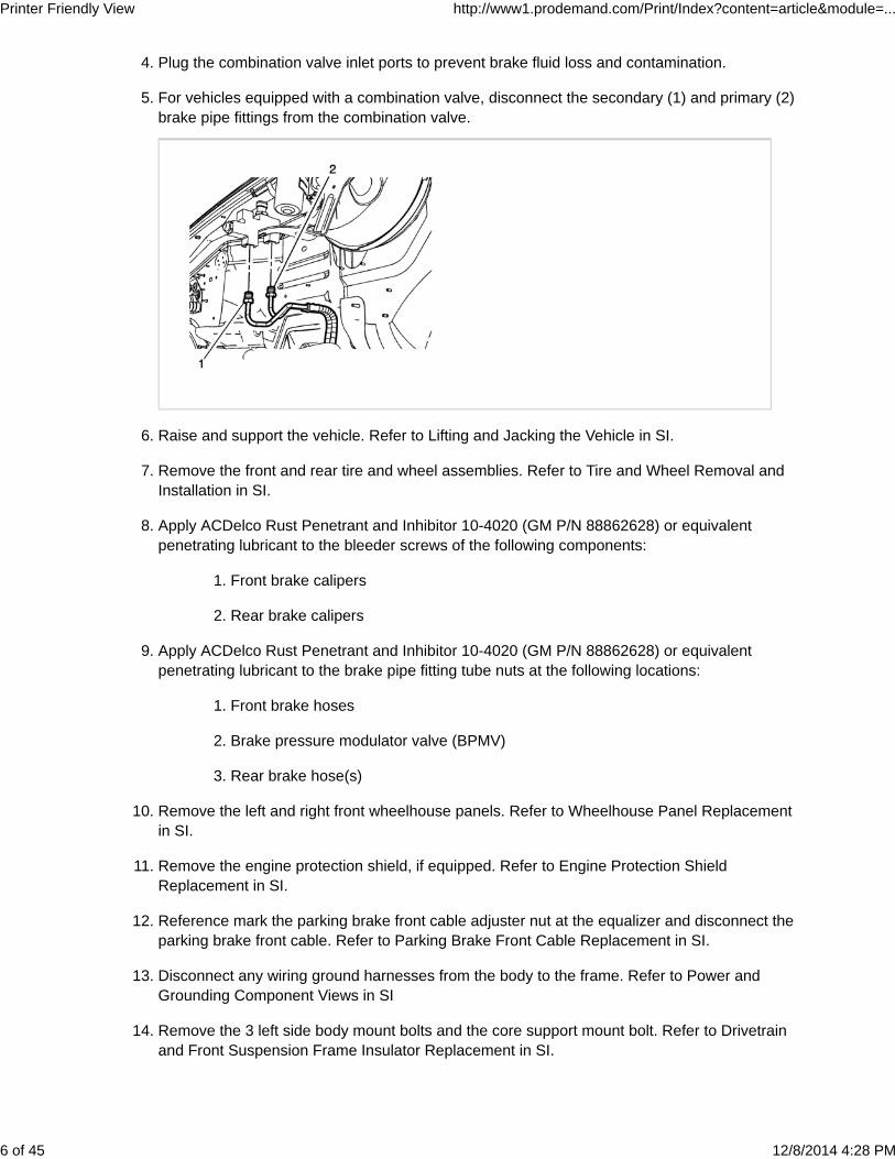
For vehicles equipped with a combination valve, disconnect the secondary (1) and primary (2)brake pipe fittings from the combination valve.
5.
Raise and support the vehicle. Refer to Lifting and Jacking the Vehicle in SI.6.
Remove the front and rear tire and wheel assemblies. Refer to Tire and Wheel Removal andInstallation in SI.
7.
Apply ACDelco Rust Penetrant and Inhibitor 10-4020 (GM P/N 88862628) or equivalentpenetrating lubricant to the bleeder screws of the following components:
Front brake calipers1.
Rear brake calipers2.
8.
Apply ACDelco Rust Penetrant and Inhibitor 10-4020 (GM P/N 88862628) or equivalentpenetrating lubricant to the brake pipe fitting tube nuts at the following locations:
Front brake hoses1.
Brake pressure modulator valve (BPMV)2.
Rear brake hose(s)3.
9.
Remove the left and right front wheelhouse panels. Refer to Wheelhouse Panel Replacementin SI.
10.
Remove the engine protection shield, if equipped. Refer to Engine Protection ShieldReplacement in SI.
11.
Reference mark the parking brake front cable adjuster nut at the equalizer and disconnect theparking brake front cable. Refer to Parking Brake Front Cable Replacement in SI.
12.
Disconnect any wiring ground harnesses from the body to the frame. Refer to Power andGrounding Component Views in SI
13.
Remove the 3 left side body mount bolts and the core support mount bolt. Refer to Drivetrainand Front Suspension Frame Insulator Replacement in SI.
Only raise the body enough to gain handaccess to the brake pipe routing clips. Paycareful attention to avoid stressing hoses andwiring harnesses.
Carefully raise the left side of the body from inboard of the frame rails approximately 51 mm (2in).
NOTE:
Place the support blocks inboard of the framerails and as close to the body mounting pointsas possible to evenly distribute the weight ofthe vehicle body.
15.
Place blocks or supports inboard of the frame side rails to support the body in at least 3locations.
16.
Remove the left side pickup box bolts and loosen, but do not remove, the right side pickup boxbolts. Refer to Pickup Box Replacement in SI.
NOTE:
Only raise the pickup box enough to gain handaccess to the brake pipe routing clips. Paycareful attention to avoid stressing hoses andwiring harnesses.
17.
Carefully raise the left side of the pickup box approximately 51 mm (2 in).
NOTE:
Place the support blocks as close to the pickupbox mounting points as possible to evenlydistribute the weight of the vehicle body.
18.
Place blocks or supports inboard of the frame side rails to support the pickup box in at least 3locations.
19.
Release the body wiring harness conduit from the brake pipe retainers on the left side of thevehicle.
Due to the similarity of the brake pipe fittingtube nuts, it is imperative to identify theindividual brake pipe locations on the BPMV toensure correct assembly.
Using side cutters, cut the left front (1) and right front (2) brake pipes as close as possible tothe brake pipe fittings at the BPMV.
34.
Using a 6 point socket, remove and discard the front brake pipe fitting tube nuts.35.
Using side cutters, cut the master cylinder primary (1) and secondary (2) brake pipes as closeas possible to the brake pipe fitting at the BPMV.
Release the rear brake pipe from the left frame rail clips (1).43.
Using side cutters, cut the rear brake pipe (1) as close as possible to the brake pipe fitting atthe rear brake hose.
44.
Using a 6 point socket, remove and discard the rear brake pipe fitting tube nut.45.
Remove the rear brake pipe from the vehicle.46.
Installation
CAUTION:
Use the correct fastener in the correct location.Replacement fasteners must be the correct partnumber for that application. Do not use paints,lubricants, or corrosion inhibitors on fasteners, orfastener joint surfaces, unless specified. Thesecoatings affect fastener torque and joint clampingforce and may damage the fastener. Use the correcttightening sequence and specifications wheninstalling fasteners in order to avoid damage toparts and systems. When using fasteners that arethreaded directly into plastic, use extreme care notto strip the mating plastic part(s). Use hand toolsonly, and do not use any kind of impact or power
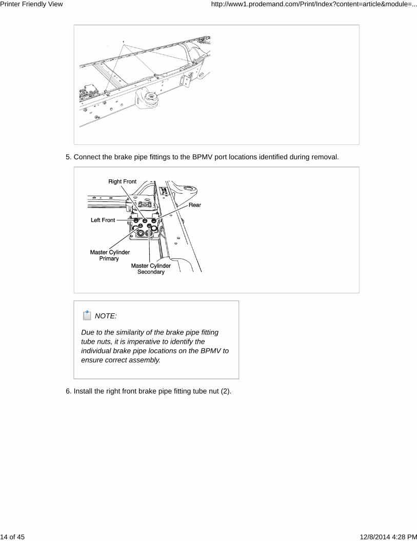
Connect the brake pipe fittings to the BPMV port locations identified during removal.
NOTE:
Due to the similarity of the brake pipe fittingtube nuts, it is imperative to identify theindividual brake pipe locations on the BPMV toensure correct assembly.
5.
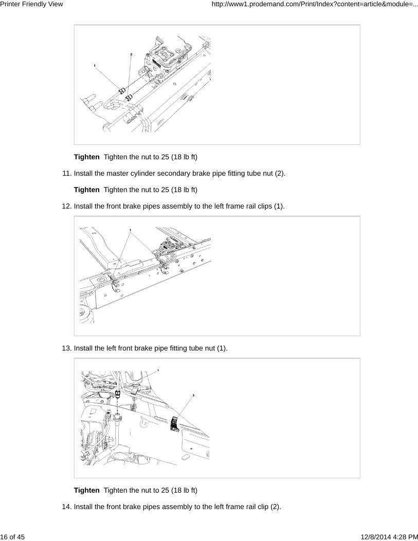
Install the right front brake pipe fitting tube nut (2).6.
Reposition the body wiring harness into the brake pipe retaining clips.19.
Remove the blocks, lower the body and install the 3 left side body mount bolts. Refer toDrivetrain and Front Suspension Frame Insulator Replacement in SI.
20.
Remove the blocks, lower the pickup box and install the pickup box bolts. Refer to Pickup BoxReplacement in SI.
21.
Inspect the pickup box for correct alignment.22.
Connect any wiring ground harnesses from the body to the frame. Refer to Power andGrounding Component Views in SI.
23.
Connect the parking brake front cable. Refer to Parking Brake Front Cable Replacement in SI.24.
Connect the left front wheel speed sensor electrical connector and install the sensor harnessretaining clips to the top of the left frame rail.
25.
Install the engine protection shield, if equipped. Refer to Engine Protection ShieldReplacement in SI.
26.
Install the left and right front wheelhouse panels. Refer to Wheelhouse Panel Replacement inSI.
27.
Lower the vehicle enough to access the combination valve and master cylinder brake pipefittings.
28.
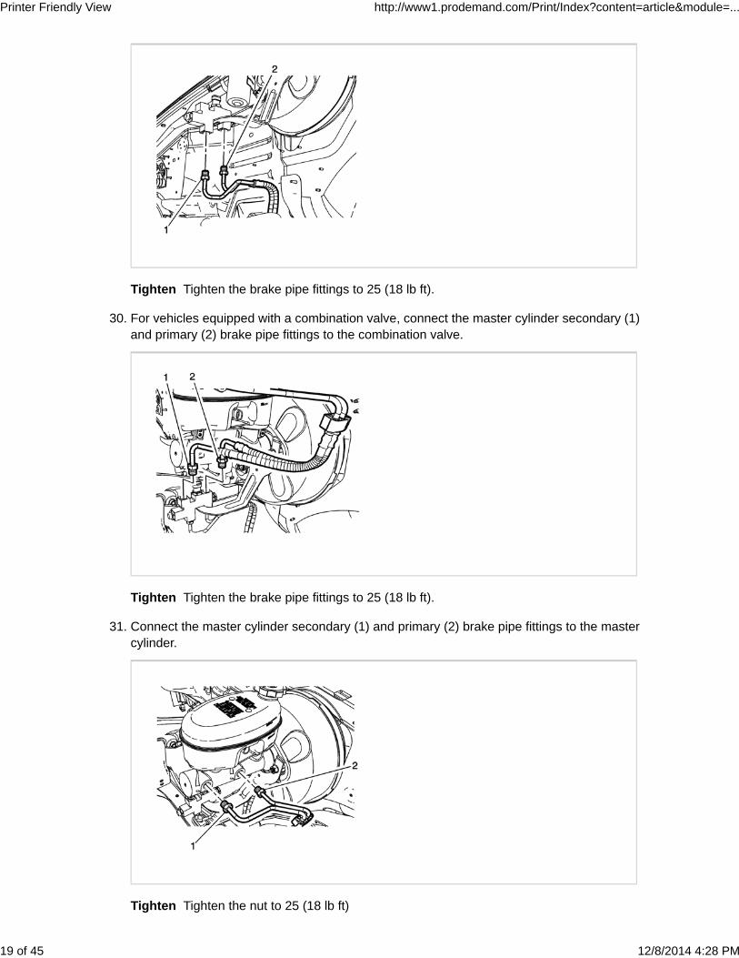
For vehicles equipped with a combination valve, connect the secondary (1) and primary (2)brake pipe fittings to the combination valve.
Bleed the hydraulic brake system. Refer to Hydraulic Brake System Bleeding in SI.32.
Install the front and rear tire and wheel assemblies. Refer to Tire and Wheel Removal andInstallation in SI.
33.
REPLACEMENT PROCEDURE (UTILITIES)
Removal
WARNING:
Brake fluid may irritate eyes and skin. In case ofcontact, take the following actions:
Eye contact-rinse thoroughly with water.
Skin contact-wash with soap and water.
If ingested-consult a physicianimmediately.
CAUTION:
Avoid spilling brake fluid onto painted surfaces,electrical connections, wiring, or cables. Brake fluidwill damage painted surfaces and cause corrosionto electrical components. If any brake fluid comes incontact with painted surfaces, immediately flush thearea with water. If any brake fluid comes in contactwith electrical connections, wiring, or cables, use aclean shop cloth to wipe away the fluid.
CAUTION:
Care should be taken to ensure that dirt, water,grease, or other contaminants do not enter the newbrake pipes and threaded end fittings when thepipes are being installed into the vehicle. Use tapeor other appropriate methods to cover the threadedend fittings and the ends of the pipes to prevent dirt,water, grease, or other contaminants from enteringthe pipes. Remove all protective measures beforeconnecting the end fittings to the master cylinder,brake pressure proportioning valve (whereequipped), brake pressure modulator valve (BPMV),or flexible brake hoses.
Cleanliness is important for the proper function ofthe hydraulic brake system. Clean all dirt, water,rust, etc from the areas adjacent to each brake pipetube nut before removing the brake pipe tube nuts.Take care to ensure that no contaminants enter anyhydraulic fittings or openings during removal orinstallation of the brake pipes.
CAUTION:
Before removing any brake pipes from the mastercylinder, ABS module (BPMV), and the brakepressure proportioning valve (where equipped)identify the port locations. On the BPMV identify theport location for each hydraulic component (e.g.,Master Cylinder Primary, Master CylinderSecondary, LF corner, RF corner, LR corner, RRcorner, Rear Brake). On the brake pressureproportioning valve identify the port locations foreach hydraulic component (e.g. master cylinderprimary inlet, master cylinder primary outlet, mastercylinder secondary inlet, master cylinder secondaryoutlet, pre-charge pump). When installing thereplacement pipes, ensure that the replacementpipes are installed in the correct port locations onthe master cylinder, BPMV, and brake pressureproportioning valve, where equipped. If the pipesare not installed in the correct port locations on allthe hydraulic components, the brake systemincluding the ABS system and/or TCS/VSESStabiltrak system (where equipped) will not operatecorrectly and may result in damage to the hydraulicbrake components.
This procedure does not comprehend specificvehicle models or brake system configurations. Theillustrations may not exactly reflect the vehicle beingrepaired. Some LD pickups and LD SUVs may beequipped with a brake pressure combination valveand a brake pressure modulator valve pre-chargepump. The brake pipes attached to thesecomponents should be removed and replaced withthe replacement pipes provided in the service kit.
NOTE:
This procedure is not intended for the repair orreplacement of a single damaged brake pipe. Thisprocedure is for the replacement of the entire brakepipe assemblies with pre-formed and pre-flaredcomponents.
NOTE:
Remove the brake pipes from the existing routingclips carefully to avoid damaging the clips as all theclips will be re-used. The new brake pipes will bereinstalled into the existing clips. After installing thenew brake pipes, inspect the routing of the brakepipes to ensure that the new brake pipes do notcontact or rub on any frame, body, or chassiscomponents. Carefully bend the pipes to increaseclearance as required.
NOTE:
The brake pipes in these kits are not an exactduplicate of the pipes currently installed on thevehicle. These pipes have a nylon coating toprovide better corrosion protection and may haveslightly different shapes and bends and may notexactly match the brake pipes being replaced.Some original equipment pipes may use flexiblehose sections near the master cylinder or brakepressure proportioning valve that attaches to themaster cylinder to brake booster mounting studs.The replacement pipes in this kit will not use the
flexible hose sections. The replacement pipes havebeen designed to fit each vehicle application.Because of the nylon coating on the outside of thebrake pipes, the outside diameter of the pipe isslightly larger than the original pipes, Extra effortmay be required to insert the pipes into the existingmounting clips. It is recommended to finger start allthe threaded end fittings into the master cylinder,brake pressure proportioning valve, brake pressuremodulation valve, and flexible brake hoses beforeperforming the final tightening and torque of eachfitting.
NOTE:
The brake pipes in these kits may have additionallarge radius shipping bends to allow the pipes to fitwithin the cardboard box. Those pipes withadditional shipping bends will have tags on eitherside of each shipping bend. Carefully straighten thesection of pipe between the tags to remove theshipping bend. Take care not to kink or damage thebrake pipes. If a brake pipe becomes kinked ordamaged while removing the shipping bends, itmust be repaired or replaced before installation intothe vehicle. Take care not to cut, nick, abrade orotherwise damage the nylon coating on the brakepipes during installation.
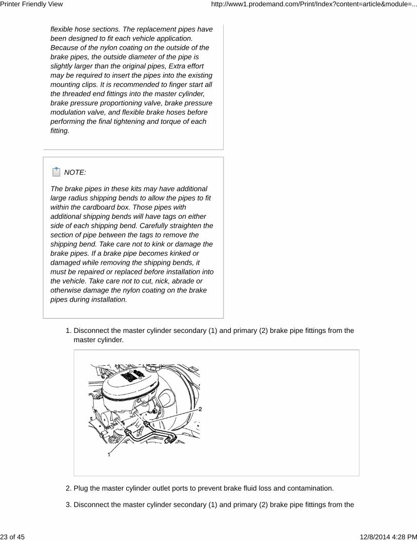
Disconnect the master cylinder secondary (1) and primary (2) brake pipe fittings from themaster cylinder.
1.
Plug the master cylinder outlet ports to prevent brake fluid loss and contamination.2.
Disconnect the master cylinder secondary (1) and primary (2) brake pipe fittings from the3.
If equipped, disconnect the BPMV front brake pipe fitting (1) from the brake pressuremodulator valve (BPMV) pre-charge pump.
9.
Plug the BPMV pre-charge pump port to prevent brake fluid loss and contamination.10.
Lower the spare tire and wheel assembly.11.
Raise and support the vehicle. Refer to Lifting and Jacking the Vehicle in SI.12.
Remove the front and rear tire and wheel assemblies. Refer to Tire and Wheel Removal andInstallation in SI.
13.
Apply ACDelco Rust Penetrant and Inhibitor 10-4020 (GM P/N 88862628 ) or equivalentpenetrating lubricant to the bleeder screws of the following components:
Front brake calipers1.
Rear brake calipers2.
14.
Apply ACDelco Rust Penetrant and Inhibitor 10-4020 (GM P/N 88862628 ) or equivalentpenetrating lubricant to the brake pipe fitting tube nuts at the following locations:
Front brake hoses1.
Brake pressure modulator valve (BPMV)2.
Rear brake hose(s)3.
15.
Remove the left and right front wheelhouse panels. Refer to Wheelhouse Panel Replacementin SI.
16.
Remove the engine shield, if equipped. Refer to Engine Shield Replacement in SI.17.
Reference mark the parking brake front cable adjuster nut at the equalizer and disconnect theparking brake front cable. Refer to Parking Brake Front Cable Replacement in SI.
18.
Disconnect any wiring ground harnesses from the body to the frame. Refer to Power andGrounding Component Views in SI.
19.
Remove the 6 left side body mount bolts and the core support mount bolt. Refer to Drivetrainand Front Suspension Frame Insulator Replacement in SI.
Only raise the body enough to gain handaccess to the brake pipe routing clips. Paycareful attention to avoid stressing hoses andwiring harnesses.
Carefully raise the left side of the body from inboard of the frame rails approximately 51 mm (2in).
NOTE:
Place the support blocks inboard of the framerails and as close to the body mounting pointsas possible to evenly distribute the weight ofthe vehicle body.
21.
Place blocks or supports inboard of the frame side rails to support the body in at least 3locations.
22.
Release the body wiring harness conduit from the brake pipe retainers on the left side of thevehicle.
23.
Position and secure the wiring harness aside.24.
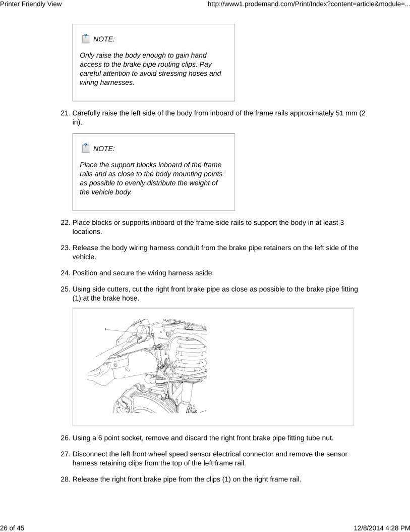
Using side cutters, cut the right front brake pipe as close as possible to the brake pipe fitting(1) at the brake hose.
25.
Using a 6 point socket, remove and discard the right front brake pipe fitting tube nut.26.
Disconnect the left front wheel speed sensor electrical connector and remove the sensorharness retaining clips from the top of the left frame rail.
27.
Release the right front brake pipe from the clips (1) on the right frame rail.28.
Due to the similarity of the brake pipe fittingtube nuts, it is imperative to identify theindividual brake pipe locations on the BPMV toensure correct assembly.
For model year 2002 vehicles equipped with RPO JL4, identify the brake pipe port locations atthe BPMV prior to disconnecting the brake pipe fittings.
NOTE:
Due to the similarity of the brake pipe fittingtube nuts, it is imperative to identify theindividual brake pipe locations on the BPMV toensure correct assembly.
37.
For model year 2003-2008 vehicles equipped with RPO JL4, identify the brake pipe portlocations at the BPMV prior to disconnecting the brake pipe fittings.
Due to the similarity of the brake pipe fittingtube nuts, it is imperative to identify theindividual brake pipe locations on the BPMV toensure correct assembly.
Using side cutters, cut the master cylinder primary (1) and secondary (2) brake pipes as closeas possible to the brake pipe fitting at the BPMV.
39.
Using a 6 point socket, remove and discard the brake pipe fitting tube nuts.40.
Using side cutters, cut the right front (1) and left front (2) brake pipes as close as possible tothe brake pipe fittings at the BPMV.
41.
Using a 6 point socket, remove and discard the front brake pipe fitting tube nuts.42.
Carefully remove the brake pipe routing clips from the front brake pipe assembly.43.
Maneuver the front brake pipes one at a time and remove the brake pipes from the vehicle.44.
Using side cutters, cut the left rear (1) and right rear (2) brake front pipes as close as possibleto the brake pipe fittings at the BPMV.
Using a 6 point socket, remove and discard the brake pipe fitting tube nuts.46.
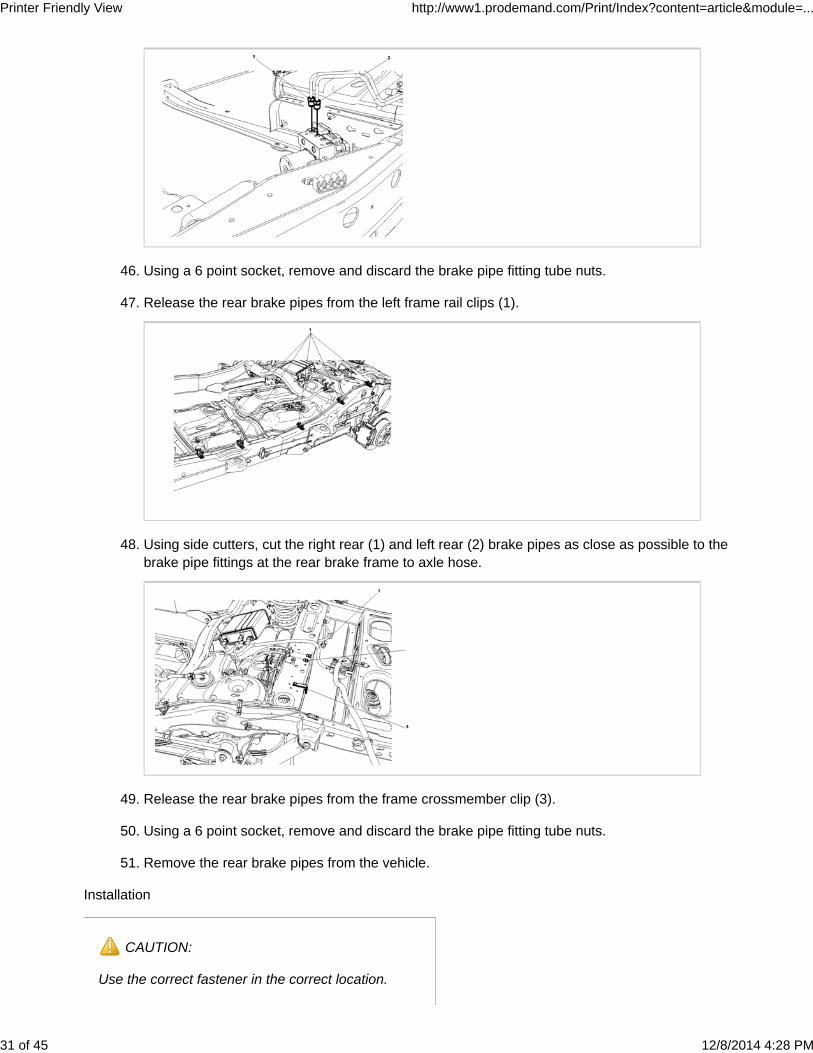
Release the rear brake pipes from the left frame rail clips (1).47.
Using side cutters, cut the right rear (1) and left rear (2) brake pipes as close as possible to thebrake pipe fittings at the rear brake frame to axle hose.
48.
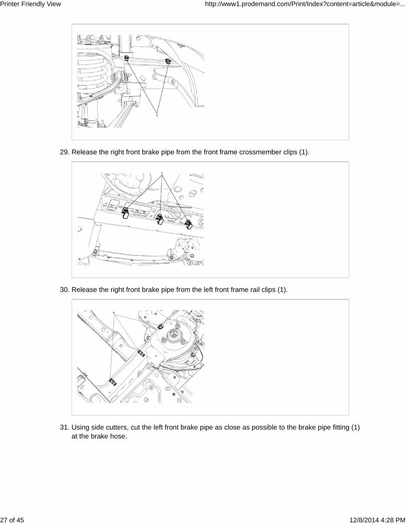
Release the rear brake pipes from the frame crossmember clip (3).49.
Using a 6 point socket, remove and discard the brake pipe fitting tube nuts.50.
Replacement fasteners must be the correct partnumber for that application. Do not use paints,lubricants, or corrosion inhibitors on fasteners, orfastener joint surfaces, unless specified. Thesecoatings affect fastener torque and joint clampingforce and may damage the fastener. Use the correcttightening sequence and specifications wheninstalling fasteners in order to avoid damage toparts and systems. When using fasteners that arethreaded directly into plastic, use extreme care notto strip the mating plastic part(s). Use hand toolsonly, and do not use any kind of impact or powertools. Fastener should be hand tightened, fullyseated, and not stripped.
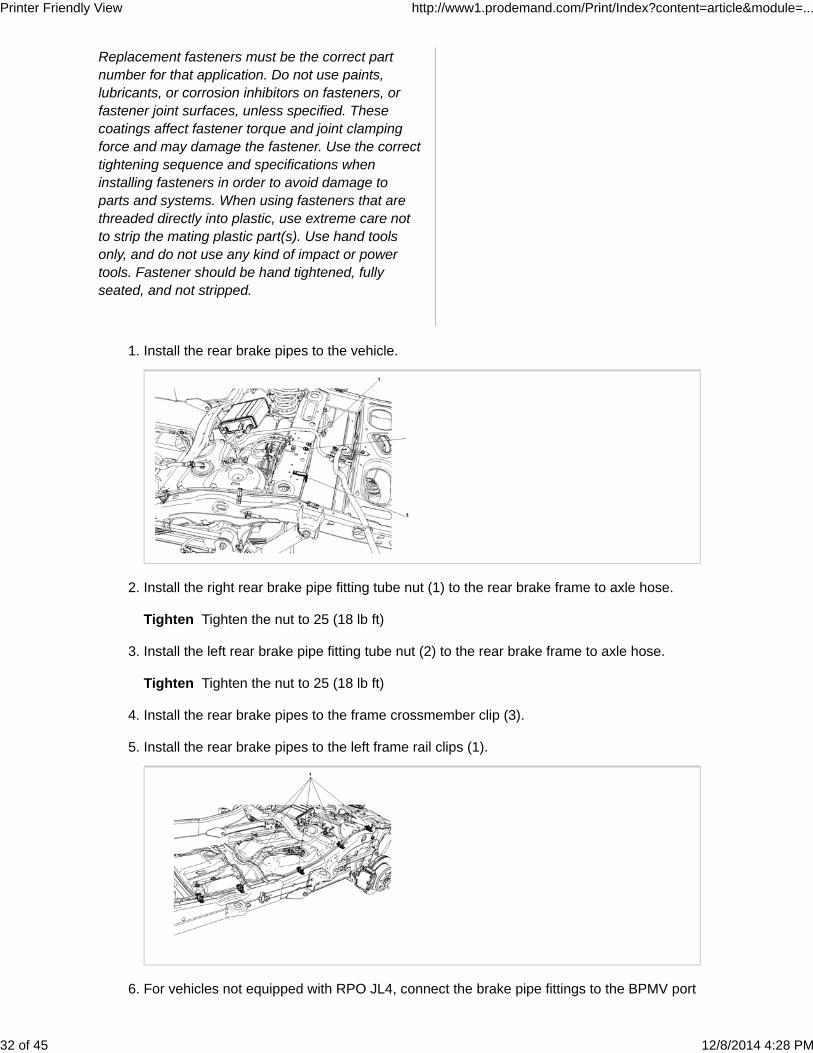
Install the rear brake pipes to the vehicle.1.
Install the right rear brake pipe fitting tube nut (1) to the rear brake frame to axle hose.
Tighten Tighten the nut to 25 (18 lb ft)
2.
Install the left rear brake pipe fitting tube nut (2) to the rear brake frame to axle hose.
Tighten Tighten the nut to 25 (18 lb ft)
3.
Install the rear brake pipes to the frame crossmember clip (3).4.
Install the rear brake pipes to the left frame rail clips (1).5.
For vehicles not equipped with RPO JL4, connect the brake pipe fittings to the BPMV port6.
Due to the similarity of the brake pipe fittingtube nuts, it is imperative to identify theindividual brake pipe locations on the BPMV toensure correct assembly.
For model year 2002 vehicles equipped with RPO JL4, connect the brake pipe fittings to theBPMV port locations identified during removal.
NOTE:
Due to the similarity of the brake pipe fittingtube nuts, it is imperative to identify theindividual brake pipe locations on the BPMV toensure correct assembly.
7.
For model year 2003-2006 vehicles equipped with RPO JL4, connect the brake pipe fittings to8.
the BPMV port locations identified during removal.
NOTE:
Due to the similarity of the brake pipe fittingtube nuts, it is imperative to identify theindividual brake pipe locations on the BPMV toensure correct assembly.
Install the left rear brake pipe fitting tube nut (1) to the BPMV.
Tighten Tighten the nut to 25 (18 lb ft)
9.
Install the right rear brake pipe fitting tube nut (2) to the BPMV.
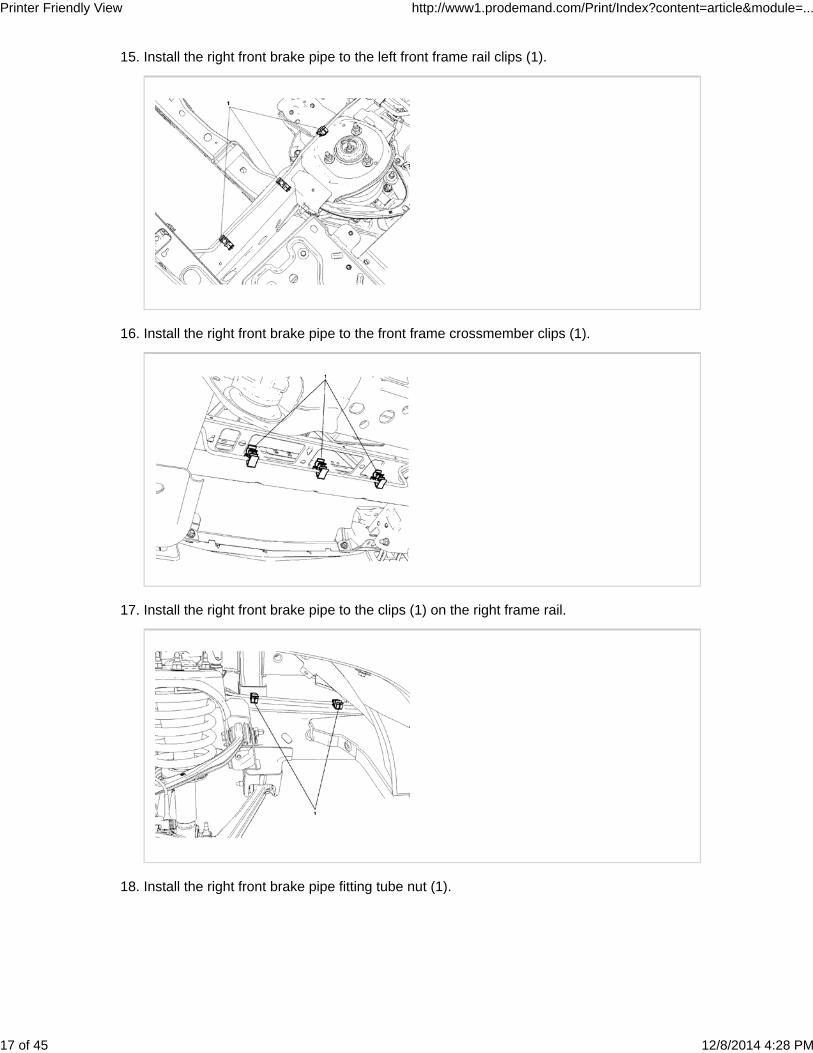
Install the right front brake pipe to the clips (1) on the right frame rail.22.
Install the right front brake pipe fitting tube nut (1).
Tighten Tighten the nut to 25 (18 lb ft)
23.
Reposition the body wiring harness into the brake pipe retaining clips.24.
Remove the blocks, lower the body and install the 6 left side body mount bolts. Refer toDrivetrain and Front Suspension Frame Insulator Replacement in SI.
25.
Connect any wiring ground harnesses from the body to the frame. Refer to Power andGrounding Component Views in SI.
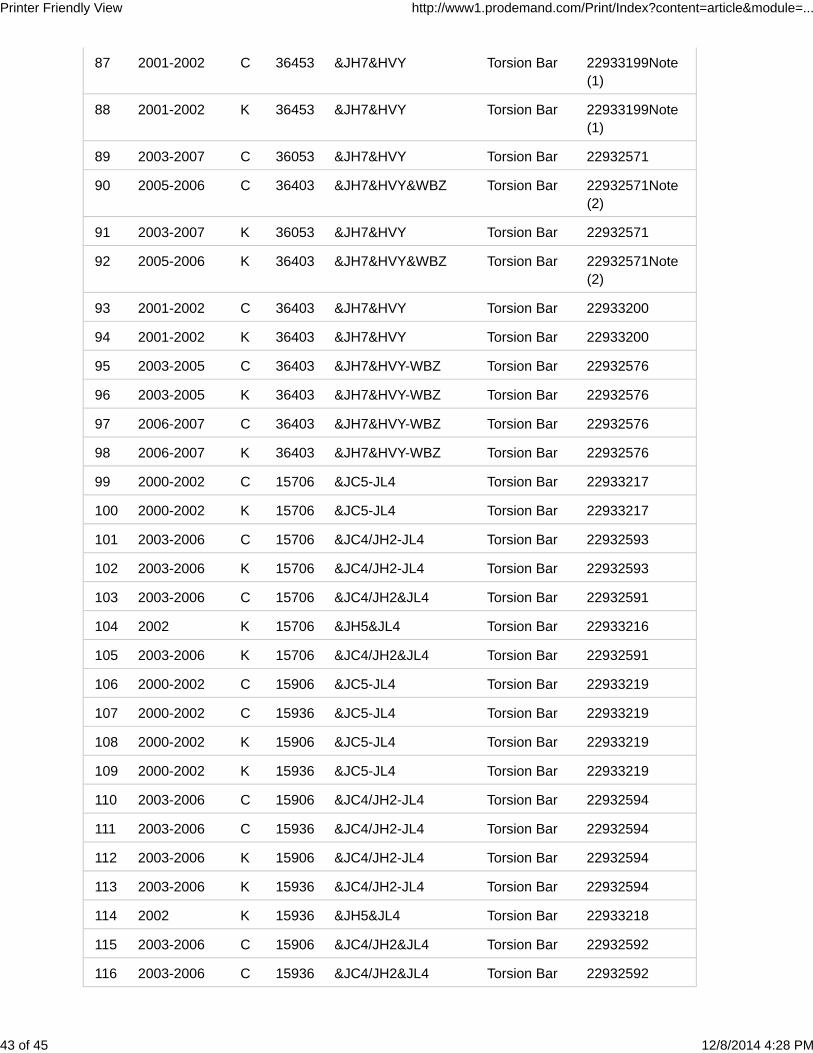
117 2003-2006 K 15906 &JC4/JH2&JL4 Torsion Bar 22932592
118 2003-2006 K 15936 &JC4/JH2&JL4 Torsion Bar 22932592
119 2000 C 25906 &JH6 Coil Spring 22933206
120 2001-2002 C 25906 &JH6 Torsion Bar 22933197
121 2002 C 25936 &JH6 Torsion Bar 22933197
122 2000-2002 K 25906 &JH6 Torsion Bar 22933197
123 2002 K 25936 &JH6 Torsion Bar 22933197
124 2003-2006 C 25906 &JH6 Torsion Bar 22932582
125 2003-2006 K 25906 &JH6 Torsion Bar 22932582
126 2003-2006 C 25936 &JH6 Torsion Bar 22932582
127 2003-2006 K 25936 &JH6 Torsion Bar 22932582
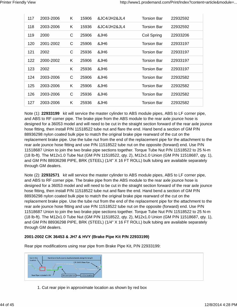
Note (1): 22933199 kit will service the master cylinder to ABS module pipes, ABS to LF corner pipe,and ABS to RF corner pipe. The brake pipe from the ABS module to the rear axle jounce hose isdesigned for a 36053 model and will need to be cut in the straight section forward of the rear axle jouncehose fitting, then install P/N 11518522 tube nut and flare the end. Hand bend a section of GM P/N88936298 nylon coated bulk pipe to match the original brake pipe rearward of the cut on thereplacement brake pipe. Use the tube nut from the end of the replacement pipe for the attachment to therear axle jounce hose fitting and use P/N 11518522 tube nut on the opposite (forward) end. Use P/N11518687 Union to join the two brake pipe sections together. Torque Tube Nut P/N 11518522 to 25 N-m(18 lb-ft). The M12x1.0 Tube Nut (GM P/N 11518522, qty. 2), M12x1.0 Union (GM P/N 11518687, qty. 1),and GM P/N 88936298 PIPE, BRK (STEEL) (1/4" X 16 FT ROLL) bulk tubing are available separatelythrough GM dealers.
Note (2): 22932571 kit will service the master cylinder to ABS module pipes, ABS to LF corner pipe,and ABS to RF corner pipe. The brake pipe from the ABS module to the rear axle jounce hose isdesigned for a 36053 model and will need to be cut in the straight section forward of the rear axle jouncehose fitting, then install P/N 11518522 tube nut and flare the end. Hand bend a section of GM P/N88936298 nylon coated bulk pipe to match the original brake pipe rearward of the cut on thereplacement brake pipe. Use the tube nut from the end of the replacement pipe for the attachment to therear axle jounce hose fitting and use P/N 11518522 tube nut on the opposite (forward) end. Use P/N11518687 Union to join the two brake pipe sections together. Torque Tube Nut P/N 11518522 to 25 N-m(18 lb-ft). The M12x1.0 Tube Nut (GM P/N 11518522, qty. 2), M12x1.0 Union (GM P/N 11518687, qty. 1),and GM P/N 88936298 PIPE, BRK (STEEL) (1/4" X 16 FT ROLL) bulk tubing are available separatelythrough GM dealers.


![Pre Rigging - boats-yachts.ro control si... · 01/2010 [B]3.a Pre Rigging Pre Rigging kit examples Pre Rigging kits: Twin digital gauge kit example 2x • Pre Rigging Dual Top Mount](https://static.documents.pub/doc/80x56/5b01b56a7f8b9a6a2e8ea25d/pre-rigging-boats-control-si012010-b3a-pre-rigging-pre-rigging-kit-examples.jpg)