1 17th Nordic Seminar on Railway Technology 3-4 October 2012 Prediction of wheel profile wear and rolling contact fatigue for the Stockholm commuter train Babette Dirks 1 , Roger Enblom 1,2 1 Royal Institute of Technology, Stockholm - Sweden 2 Bombardier Transportation, Västerås - Sweden
Transcript
117th Nordic Seminar on Railway Technology
3-4 October 2012
Prediction of wheel profile wear and rolling contact fatigue for the Stockholm
commuter train
Babette Dirks1, Roger Enblom1,2
1Royal Institute of Technology, Stockholm - Sweden2Bombardier Transportation, Västerås - Sweden
2
Overview
• Project goals• Scope of this presentation• Methods• Results• Conclusions
3
Project
• The main goals of the project are:o To create one model for prediction of the total
expected life of wheels and railso Selection of reference vehicles, lines and curves
for validation of the modelso Perform/collect measurementso Validation of the modelo Apply the model to investigate the influence of
• To study the behavior of two reference vehicles with respect to wear and RCF of the wheels.o Two wear and two RCF prediction models
have been used in combination with vehicle dynamics simulations.
o Multi-body simulations in Gensys provided the input to the wear and RCF models
5
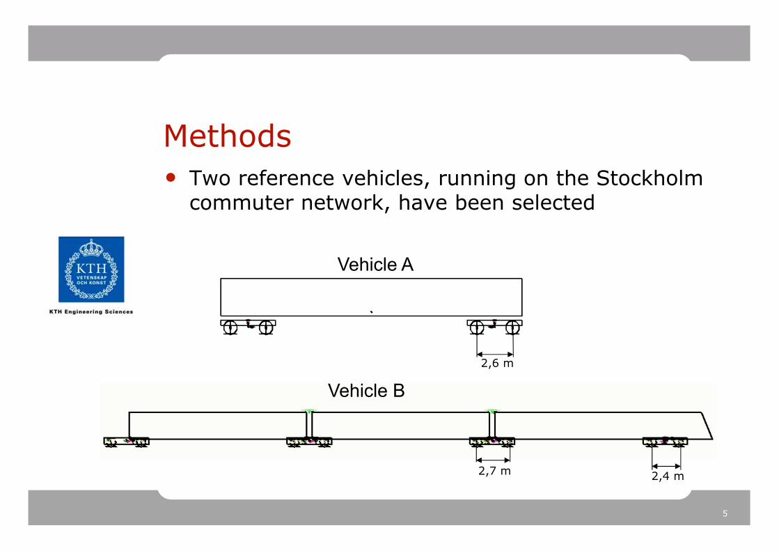
Methods• Two reference vehicles, running on the Stockholm
commuter network, have been selected
•2,6 m
Vehicle B
Vehicle A
•2,4 m•2,7 m
6
Methods – RCF models
• Two RCF initiation prediction models have been studied and compared:o 1) based on the shear stress (SI-model)o 2) based on the energy dissipation (DI-model)
7
Methods – RCF models
• Surface initiated RCF index (SI) of the form:
0)( >−= kSI τ
•τ is the shear stress [N/m2]
•k is the yield stress in shear [N/m2]
•p is the contact pressure [N/m2]
0)(>
−=
p
kFI
τ•Shakedown map
8
Methods – RCF models• Rail RCF model based on Tγ (DI-model)
yyxx TTT γγγ ⋅+⋅=
0 100 200 300-15
-10
-5
0
5
10
15
Tγγγγ [N]
RC
F D
am
age Index (*1
0-6
)
•Tx is the longitudinal creep force [N]
•Ty is the lateral creep force [N]
•γx is the longitudinal creep [-]
•γy is the lateral creep [-]
9
Methods – wear models
• Two wear prediction models have been studied and compared:o 1) wear model according to Pearce and Sheratt
(based on the energy dissipation)o 2) Archard’s wear model
10
Methods – wear models
γ⋅⋅= TCAW
0 50 100 150 200 250 3000
2
4
6
8x 10
-10 Wear according to PSH, one wheel revolution
T γγγγ [N]
Wear [m
2]
•Tγγγγ [N]
•AW[m
2]
•Wear for one wheel revolution
AW=worn-off area per wheel revolution
T=creep force
γ =creepage
• Pearce and Sheratt (PSH) wear model
11
Methods – wear models
• Archard wear model (AR)
H
sNkVw
⋅⋅=
Vw = wear volume s = sliding distance N = normal forceH = hardness k = wear coefficient ∆z = wear depthpz = contact pressure
H
spkz z ∆
∆⋅
⋅=
12
Methods – wear models
Wear coefficient, k (dry) [10-4]
0,0
0,5
1,0
1,5
2,0
2,5
3,0
0 0,2 0,4 0,6 0,8 1Sliding velocity [m/s]
Pre
ssure
[GPa]
k3 = 30-40k 2
= 1
-10
k 4 =
1-1
0
k1 = 300-400
13
Results - curving
0 200 400 600 800 1000-2
0
2
4
6
8x 10
-3
Position [m]
Angle
of att
ack [ra
d]
Long transition curve
A axle 1
B axle 1
B axle 3
•(R=∞ -> R=300 m)
•V
14
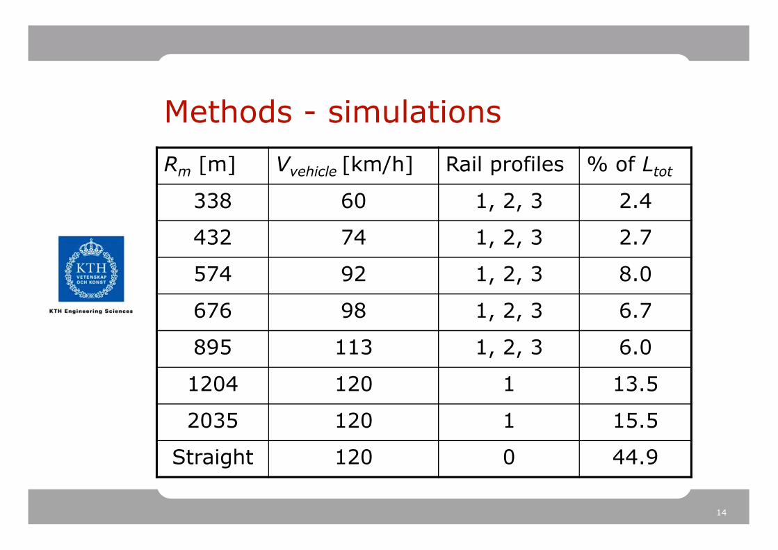
Methods - simulations
Rm [m] Vvehicle [km/h] Rail profiles % of Ltot
338 60 1, 2, 3 2.4
432 74 1, 2, 3 2.7
574 92 1, 2, 3 8.0
676 98 1, 2, 3 6.7
895 113 1, 2, 3 6.0
1204 120 1 13.5
2035 120 1 15.5
Straight 120 0 44.9
15
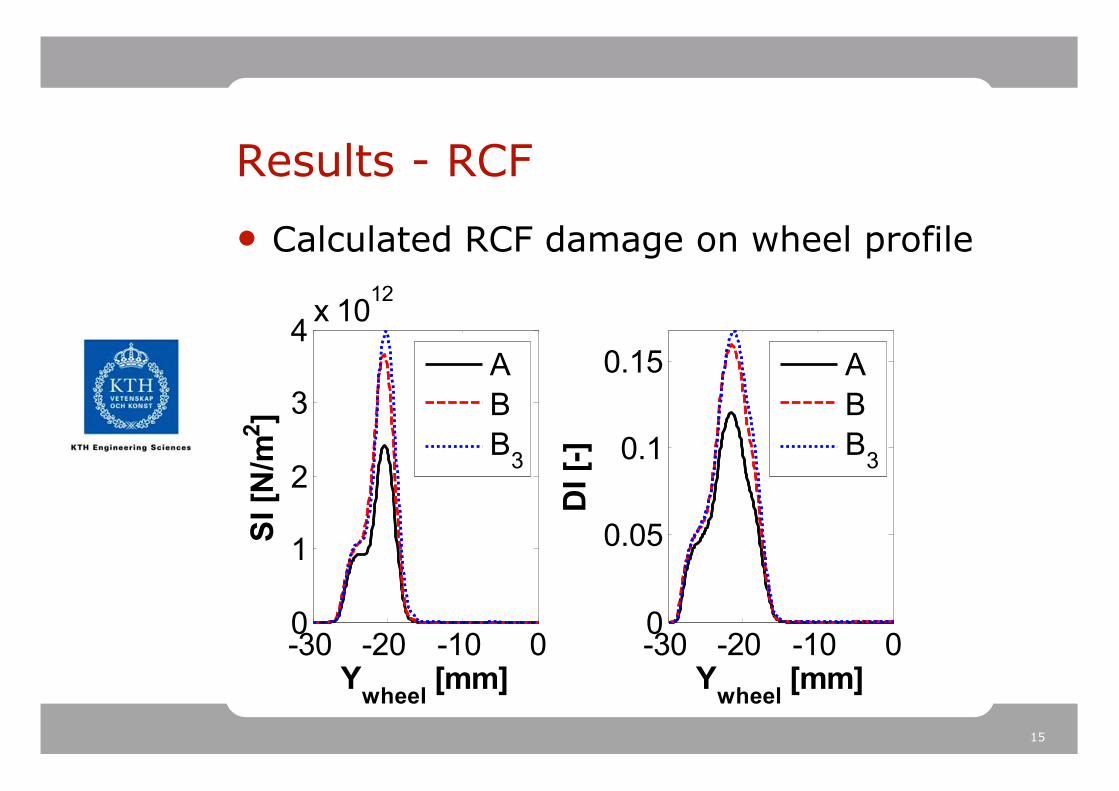
Results - RCF
-30 -20 -10 00
1
2
3
4x 10
12
Ywheel
[mm]
SI [N
/m2]
A
B
B3
-30 -20 -10 00
0.05
0.1
0.15
Ywheel
[mm]
DI [-]
A
B
B3
• Calculated RCF damage on wheel profile
16
Results - RCF
• Limitation of the creep forces for high creepages (full slip) for SI-model.
0 0.002 0.004 0.006 0.008 0.010
0.2
0.4
Inner wheel
Creep [-]
µµ µµ=F
T/F
Z [-]
00 >−⋅= kpF
FSI
z
T
yyxx TTTDI γγγ ⋅+⋅=:
17
RCF inspections vehicle B
•High lateral creep forces
18
Results - wear
• Calculated wear depth on wheel profile
-30 -20 -10 00
0.5
1
1.5
x 10-4
Ywheel
[mm]
dz A
R [m
]
A
B
B3
-30 -20 -10 00
0.5
1
1.5
x 10-4
Ywheel
[mm]
dz P
SH
[m
]
A
B
B3
19
Results - wear
• Wear map for single contact in curve
0 0.5 10
0.5
1
1.5
2
2.5
vslip
[m/s]p [G
Pa]
R676, vehicleB
0 0.5 10
0.5
1
1.5
2
2.5
vslip
[m/s]
p [G
Pa]
R676, vehicleA
•k3=30-40
•k2=
1-1
0
•k3=30-40
•k2=
1-1
0
20
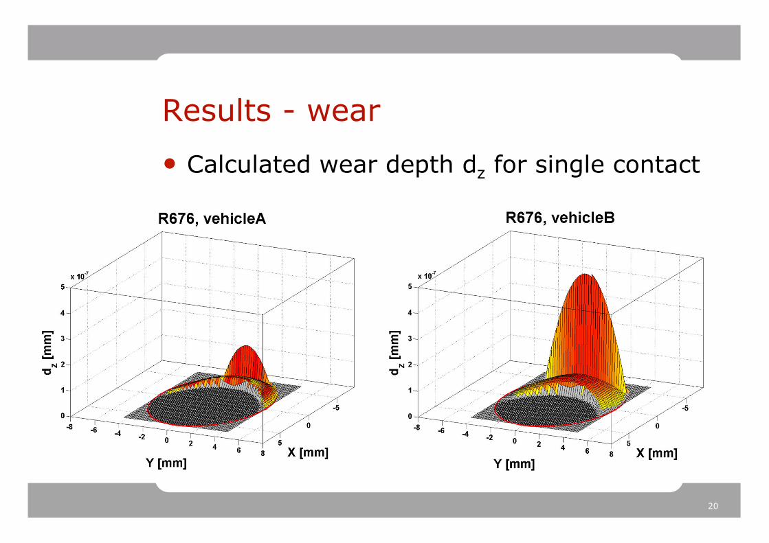
Results - wear
• Calculated wear depth dz for single contact
21
Conclusions
• The following main conclusions can be drawn for the RCF prediction models:o Both RCF models predict more damage for vehicle B
than for vehicle A due to the better steering performance of vehicle A
o Under poor adhesion conditions, however, the models behave differently: • The SI-model predicts less damage for high
creepages, due to the independence on creepage• Previous research, however, has also shown that
high creepage has no effects on RCF life.
• The RCF inspections of the wheels of vehicle B show that the steering of the axles under certain circumstances can be poor.
22
Conclusions
• The following main conclusions can be drawn for the wear prediction models:o Both wear models predict more wear for vehicle B
than for vehicle A due to the better steering performance of vehicle A
o The Archard’s wear model predicts more wear due to the large influence of the sliding velocity in the wear map, therefore, especially for vehicle B.