Page 1
PREFORM DESIGN FOR FORGING OF HEAVY VEHICLE STEERING JOINT
A THESIS SUBMITTED TO
THE GRADUATE SCHOOL OF NATURAL AND APPLIED SCIENCES
OF
THE MIDDLE EAST TECHNICAL UNIVERSITY
BY
SERTAN GÜLBAHAR
IN PARTIAL FULFILMENT OF THE REQUIREMENTS FOR THE DEGREE OF
MASTER OF SCIENCE
IN
THE DEPARTMENT OF MECHANICAL ENGINEERING
JANUARY 2004
Page 2
Approval of the Graduate School of Natural and Applied Sciences
______________________
Prof. Dr. Canan ÖZGEN Director
I certify that this thesis satisfies all the requirements as a thesis for the degree of
Master of Science
______________________
Prof. Dr. Kemal İDER Head of the Department
This is to certify that we have read this thesis and that in our opinion it is fully
adequate, in scope and quality, as a thesis for the degree of Master of Science
_____________________
Prof. Dr. Mustafa İlhan GÖKLER Supervisor
Examining Committee Members:
Prof. Dr. R. Orhan YILDIRIM ______________________
Prof. Dr. Mustafa İlhan GÖKLER ______________________
Prof. Dr. Haluk DARENDELİLER ______________________
Prof. Dr. Kemal İDER ______________________
Prof. Dr. Can ÇOĞUN ______________________
Page 3
iii
ABSTRACT
PREFORM DESIGN FOR FORGING OF HEAVY VEHICLE
STEERING JOINT
GÜLBAHAR, Sertan
M. Sc., Department of Mechanical Engineering
Supervisor: Prof. Dr. Mustafa İlhan GÖKLER
January 2004, 114 pages
In automotive industry, forgings are widely used especially in safety
related applications, typically suspension, brake and steering systems. In this
study, forging process of a steering joint used in heavy vehicles has been
examined. This particular part has a non-planar parting surface and requires a
series of operations, which includes fullering, bending and piercing on a forging
press. Forging companies generally use trial-and-error methods during the design
stage. Also to ensure complete die filling at the final stage, extra material is
added to the billet geometry. However, the forging industry is becoming more
competitive finding a way to improve the quality of the product while reducing
the production costs.
For this purpose, a method is proposed for the design of the preform dies
to reduce the material wastage, number of applied strokes and production costs.
The designed operations were examined by using a commercially available finite
volume analysis software. The necessary dies have been manufactured in
METU-BILTIR CAD/CAM Center. The designed process has been verified by
Page 4
iv
the experimental work in a forging company. As a result of this study,
remarkable reduction in the flash, i.e. waste of material, has been achieved with a
reasonable number of forging operations.
In addition to forging of the steering joint, forging of a chain bracket,
which has bent sections with planar parting surface, has also been observed and
analyzed during the study. An intermediate bending stage has been proposed to
replace the manual hammering stage and satisfactory results have been observed
in simulations.
Keywords: Metal Forming, Press Forging, Hammer Forging, Hot Forging,
Open-Die Forging, Closed-Die Forging, Preform Design, Finite Volume
Analysis
Page 5
v
ÖZ
AĞIR VASITA SÜRÜŞ SİSTEMİ BAĞLANTI PARÇASININ DÖVME
İŞLEMİ İÇİN ÖNFORM TASARIMI
GÜLBAHAR, Sertan
Yüksek Lisans, Makina Mühendisliği Bölümü
Tez Yöneticisi: Prof. Dr. Mustafa İlhan GÖKLER
Ocak 2004, 114 sayfa
Dövme parçaları, otomotiv endüstrisinde, özellikle süspansiyon, fren ve
sürüş sistemlerinde, gibi güvenlik ile ilgili uygulamalarda yaygın olarak
kullanılmaktadır. Bu çalışma dahilinde ağır vasıta sürüş sistemi bağlantı
parçasının dövme prosesi incelenmiştir. Bu parça, düzlemsel olmayan ayırma
yüzeyine sahip olup, dövme presinde uzama, bükme ve delme işlemlerine ihtiyaç
duymaktadır. Dövme firmaları tasarım sürecinde genellikle deneme yanılma
yöntemini kullanmaktadır. Ayrıca, son aşamada kalıbın tam olarak dolduğundan
emin olmak için, başlangıç parça hacmine ekstra malzeme eklemektedirler. Fakat
dövme endüstrisi, üretim fiyatlarını azaltıp, kaliteyi arttırma yönünde gittikçe
daha rekabetçi olmaktadır.
Bu amaç doğrultusunda malzeme kaybını, vuruş sayısını ve üretim
maliyetini azaltmak amacıyla önform kalıplarının tasarımı için bir metod
önerilmiştir. Tasarlanmış operasyonlar ticari sonlu hacim analiz yazılımı
kullanılarak incelenmiştir. Gerekli kalıplar ODTÜ-BİLTİR CAD/CAM
Page 6
vi
Merkezinde üretilmiştir. Tasarlanmış prosesin doğruluğu bir dövme firmasında
yapılan testler sonucunda kanıtlanmıştır. Bu çalışmanın sonucunda makul sayıda
dövme operasyonu kullanılarak çapak miktarında (malzeme kaybında) önemli
oranda azalma sağlanmıştır.
Sürüş bağlantı parçasının dövme işlemine ek olarak, düzlemsel kalıp
ayırma yüzeyine sahip, bükülmüş kısımlardan oluşan mapa parçasının dövme
işlemi incelenmiş ve analiz edilmiştir. Elle yapılan çekiçleme aşamasının yerine,
bir ara bükme aşaması önerilmiş ve yapılan simülasyonlarda tatmin edici
sonuçlar elde edilmiştir.
Anahtar Kelimeler: Metal Çekillendirme, Pres Dövme, Çekiç Dövme, Sıcak
Dövme, Açık Kalıpta Dövme, Kapalı Kalıpta Dövme, Ön Şekil Tasarımı, Sonlu
Hacim Analizi
Page 8
viii
ACKNOWLEDGEMENTS
I express sincere appreciation to Prof. Dr. Mustafa İlhan GÖKLER for
his guidance and insight during the study.
I wish to thank to Mrs. Tülay KÖMÜRCÜ, Mr. Cevat KÖMÜRCÜ,
Mrs.Tülin ÖZKAN and Mr. Cihan AYDIN from AKSAN Steel Forging
Company. The technical assistance of them is gratefully acknowledged. I also
would like to thank to METU-BILTIR CAD/CAM/Robotics Center for the
facilities provided for this study.
Special thanks go to my colleagues, Mehmet TUNÇ, Barış
KARAGÖZLER, Barış CİVELEKOĞLU, Özkan İLKGÜN, Ender CENGİZ and
Suphi YILMAZ for their valuable support.
To my parents, Nevin and Vural GÜLBAHAR, my sister Nergiz AKIN
and her husband Ali AKIN, I offer sincere thanks for their encouragement.
I wish to thank to my dear wife Işıl for her signifant supports and
encouregement. I am appreciative for her eternal patience.
Page 9
ix
TABLE OF CONTENTS
ABSTRACT ........................................................................................................... iii
ÖZ…………………………………………………………………………...…..... v
ACKNOWLEDGMENTS.................................................................................... viii
TABLE OF CONTENTS ....................................................................................... ix
LIST OF TABLES ................................................................................................ xii
LIST OF FIGURES.............................................................................................. xiv
LIST OF SYMBOLS............................................................................................ xix
CHAPTER
1. INTRODUCTION...................................................................................... 1
1.1 Forging Process ................................................................................... 2
1.1.1 Classification of Forging Process According toTemperature .... 2
1.1.2 Types of Machine Used ............................................................. 3
1.1.3 Types of Die Set ........................................................................ 5
1.2 Forging Defects and Error Sources in Forgings.................................. 6
1.3 Usage of CAD/CAM/CAE for Analysis of Forging Process .............. 9
1.4 Scope of the Thesis............................................................................ 11
2. DESIGN FOR FORGING PROCESS .................................................... 13
2.1 Forging Part Design........................................................................... 14
2.1.1 Location of Parting Line .......................................................... 14
Page 10
x
2.1.2 Draft Angle .............................................................................. 17
2.1.3 Corner and Fillet Radii ............................................................ 18
2.1.4 Scale Allowance ....................................................................... 19
2.2 Flash Design ...................................................................................... 20
2.3 Process Sequence and Preform Design ............................................. 26
2.3.1 Types of Preform Impressions in Dies .................................... 28
2.4 Prediction of Pressure, Load and Energy in Closed-Die Forging ..... 30
3. PROPOSED METHOD FOR PREFORM DESIGN FOR BENT
FORGINGS.............................................................................................. 32
3.1 Parting Line and Surface Construction ............................................. 32
3.2 Estimation of the Flash Volume........................................................ 34
3.3 Analysis of the CAD Model.............................................................. 36
3.4 Decision of Billet Geometry and Dimensions................................... 38
3.5 Preform Design and Modeling .......................................................... 39
3.6 Analysis of Designs using Finite Volume Method ........................... 43
3.7 Iteration and Verification of the Preform Geometry ......................... 46
4. MODELLING AND COMPUTER SIMULATION OF FORGING OF
CHAIN BRACKET.................................................................................. 49
4.1 Current Practice in the Company ...................................................... 50
4.2 Analysis of the Current Practice........................................................ 54
5. MODELLING, COMPUTER SIMULATION, AND REAL-LIFE
EXPERIMANTATION OF STEERING JOINT .................................... 61
5.1 Geometry of the Forged Part ............................................................ 61
Page 11
xi
5.2 Current Practice in the Company ..................................................... 63
5.3 Proposed Preform Design................................................................. 69
5.4 Design of the Preforms and Analysis of the Stages ......................... 77
5.4.1 Upsetting Operation ................................................................ 77
5.4.2 Fullering Operation ................................................................. 80
5.4.3 Bending Operation .................................................................. 83
5.4.4 Blocking Operation ................................................................. 85
5.4.5 Finishing Operation ................................................................. 87
5.5 Design and Manufacture of the Die Sets.......................................... 89
5.6 Real-Life Experimentation ............................................................... 92
6. CONCLUSIONS..................................................................................... 97
6.1 Discussions and Conclusions ........................................................... 97
6.2 Future Work ..................................................................................... 99
REFERENCES.................................................................................................... 100
APPENDICES
A. TECHNICAL DRAWING OF CHAIN BRACKET............................ 105
B. MATERIAL PROPERTIES OF DIN 1.0503 STEEL.......................... 106
C. TECHNICAL DRAWING OF “BALL JOINT” .................................. 108
D. RECOMMENDATIONS FOR UPSETTING OPERATION .............. 109
E. SIMULATION PARAMETERS USED FOR THE ANALYSIS
OF “BALL JOINT”.............................................................................. 111
Page 12
xii
LIST OF TABLES
TABLE
1.1 Classification of Scrap Metal in Hot Forging according to Fault Types. 8
2.1 General Recommendations for Minimum Fillet and Corner Radii ........ 19
2.2 Scale Allowance Values......................................................................... 20
2.3 Recommendation of NADF for Flash Mass of the Forging................... 26
4.1 Operation Sheet for Chain bracket (DIN 745 – 63) ............................... 50
4.2 AverageDimensions of the Final Flash Width for the Sample Parts
and the Simulation Result....................................................................... 59
5.1 Operation Sheet of “Ball Joint”.............................................................. 64
5.2 Production Data of “Ball Joint”.............................................................. 68
5.3 Volume Decomposition Results for “Ball Joint” ................................... 75
5.4 Dimension Ranges for Two Different Billet Geometry Options ........... 75
5.5 Average Dimensions for Square and Round Billet at Each Section ...... 76
5.6 Results of the Computer Simulations..................................................... 88
5.7 Results of the Experiments..................................................................... 92
5.8 Study Results of the “Ball Joint”............................................................ 96
D.1 Draft Angle Recommendations ........................................................... 109
D.2 Recommendations for Corner Radius ................................................. 110
Page 13
xiii
E.1 “4000 tonf” Press Parameters .............................................................. 112
Page 14
xiv
LIST OF FIGURES
FIGURE
1.1 Typical Cause of Flow-through Defects ................................................. 7
2.1 Forging with Straight Parting Line....................................................... 15
2.2 Forging with Broken Parting Line........................................................ 15
2.3 (a) Die Set with Counterlock; (b) Balanced Pair of Forgings in a
Single Die Set ...................................................................................... 16
2.4 Die Set for Producing a Forging with Broken Parting Line ................ 17
2.5 Basic Types of Drafts ........................................................................... 17
2.6 Illustration of Corner and Fillet Radii for a Part ................................. 18
2.7 Flash Distribution for a Forged Part..................................................... 21
2.8 Typical Forging-Load Curve for Closed-Die Forging ......................... 22
2.9 Preform and Final Stages of a Forged Part........................................... 27
2.10 Typical Multiple Impression Dies for Closed-Die Forging ................. 30
3.1 Parting Line Types ............................................................................... 33
3.2 Non-planar Parting Surface Arrangement of a Part ............................. 34
3.3 Non-uniform Flash Distribution of a Forged Part ................................ 35
3.4 X-Section Analysis with Pro/E............................................................. 37
3.5 Datum Planes Constructed on an Example Wireframe Model............. 37
Page 15
xv
3.6 (a) CAD model of the a Part; (b)Volume Distribution Curves for the
Part........................................................................................................ 40
3.7 Parting Surface and Die Block Arrangement of a Sample Part ........... 42
3.8 Upper and Lower Dies of a Sample Part .............................................. 43
3.9 Sample View of a Simulation Performed in MSC.Superforge ............ 46
4.1 Chain Bracket (DIN 745 – 63) ............................................................. 49
4.2 An Industrial Application of Chain Bracket......................................... 50
4.3 (a) “5000 KGM” Drop Hammer; (b) “200 tonf” Mechanical Press..... 51
4.4 Die Sets of 1st and 2nd Preform Operations .......................................... 52
4.5 (a) Part before 1st Preform; (b) Part after 1st Preform; (c) Part after 2nd
Preform................................................................................................. 52
4.6 Die Set of Finishing Operation and a Sample Part at Finisher Stage... 53
4.7 Parts with Flash After Finishing Operation (for 20 and 22 mm
diameter of billet) ................................................................................. 53
4.8 Proposed Preform Geometries.............................................................. 54
4.9 CAD Models of 1st and 3rd Preform Operation Die Set ....................... 55
4.10 Simulation Set-up of 1st Preform Operation......................................... 56
4.11 Simulation Set-up of Proposed Bending Operation ............................. 57
4.12 Simulation Results of Preforming Operations...................................... 58
4.13 Die Contact Analysis After 3 Blows of Finishing Dies ....................... 60
4.14 Flash Formation After the Finishing Stage for the Current Process .... 60
5.1 “Ball Joint” ........................................................................................... 62
5.2 Parting Surface Orientation of “Ball Joint”.......................................... 62
Page 16
xvi
5.3 “4000tonf” Press Line at AKSAN........................................................ 63
5.4 “970 kW” Induction Furnace of “4000tonf” Press Line ...................... 63
5.5 Preform after Upsetting ........................................................................ 65
5.6 Preform after 1st Fullering Operation ................................................... 65
5.7 Preform after 2nd Fullering Operation .................................................. 66
5.8 Preform after Bending Operation ......................................................... 66
5.9 Preform after Blocking Operation ....................................................... 67
5.10 Part after Finishing Operation .............................................................. 67
5.11 Two Different Flash Formation Occur at Finishing Operation............ 68
5.12 Solid Model of “Ball Joint” Created by Using Pro/E........................... 69
5.13 Projected Area of “Ball Joint” Calculated by Using Pro/E .................. 70
5.14 The 3-D Model of the “Ball Joint” with the Estimated Flash
Geometry .............................................................................................. 71
5.15 Datum Planes Placed on the Model for Volume Distribution Curve
Plotting ................................................................................................. 72
5.16 A Sample Cross-Section Calculation for “Ball Joint”.......................... 72
5.17 (a) Reference 3-D Model; (b) Volume Distribution Curves for “Ball
Joint” .................................................................................................... 73
5.18 Preform Geometry After Upsetting Operation..................................... 78
5.19 One of the Die of the Upsetting Stage.................................................. 79
5.20 Simulation Set-up of 1st Preform (Upset) Operation............................ 79
5.21 Result After 1st Preform Operation ...................................................... 80
5.22 Sections on the Preoform Geometry of the Fullering Stage................. 81
Page 17
xvii
5.23 3-D Model of the Preform Geometry After the Fullering Operation ... 81
5.24 One of the Die of the Fullering Stage................................................... 82
5.25 Simulation Set-up of 2nd Preform (Fullering) Operation...................... 82
5.26 Resultant Preform Geometry After Six Fullering Operation ............... 83
5.27 Side View of the Die Set of the Bending Stage ................................... 83
5.28 Simulation Set-up of 3rd Preform (Bending) Operation ....................... 84
5.29 Resultant Preform Geometry After the Bending Operation................. 84
5.30 3-D Model of the Aimed Part at the Blocker Stage ............................. 85
5.31 Simulation Set-up of 4th Preform (Blocking) Operation ...................... 86
5.32 Preform Geometry After the 4th Preform (Blocking) Operation .......... 86
5.33 Simulation Set-up of the Final Forging Stage ...................................... 87
5.34 Die Contact (Die Fill) Analysis of the Finishing Operation ................ 88
5.35 (a) Created Models of the Dies; (b) Assembly Model of the Dies....... 89
5.36 Manufactured Dies of 1st and 3rd Preform Operation (Upsetting and
Bending) ............................................................................................... 90
5.37 (a) Created Model of the 2nd Preform (Fullering) Operation Die;
(b) Assembly Model of the Dies; (c) One of the Manufactured Die.... 90
5.38 (a) Created Models of the Die of 4th Preform (Blocking) Operation;
(b) Assembly Model of the Dies; (c) Manufactured Dies .................... 91
5.39 Unsatisfactory Sample of the First Experiment ................................... 93
5.40 Samples of the Preform Operations...................................................... 94
5.41 Part After the Finishing Operation ....................................................... 94
5.42 Sample Preform Geometries After the Blocking Operation ................ 95
Page 18
xviii
A.1 Technical Drawing of “Chain Bracket” .............................................. 105
B.1 Material Properties of DIN 1.0503 ...................................................... 107
C.1 Technical Drawing of “Ball Joint” ...................................................... 108
D.1 Corner and Fillet Radii ........................................................................ 109
D.2 Suggested Relationship Between Unsupported Bar Length Beyond
Cavity and Maximum Taper Diameter................................................ 110
E.1 Illustration of Mechanical Press Parameters Expressed by
MSC.Superforge.................................................................................. 112
E.2 Illustration of Friction Models ............................................................. 114
Page 19
xix
LIST OF SYMBOLS
SYMBOL
Ac Mean Cross-sectional Area of the Part
At Total Projected Area of the Forging
D Billet Diameter
Dc Diameter of the Circumscribing Cylinder of the Forging
Do Diameter of the Initial Round Stock
Fa Surface Area of the Axial Cross-section of the Forging, Includes
the Entire Axis of Symmetry
Fc Surface Area of the Axial Cross-section of the Cylinder,
Circumscribes the Forging
Lb Length of the Billet
m Interface Friction Factor
P Perimeter of the Axial Cross-section of the Forging
Pc Perimeter of the Axial Cross-section of the Cylinder,
Circumscribes the Forging
Rc Maximum Radius of the Forged Part, Equla to the Radius of the
Circumscribing Cylinder
Rg Radial Distance from the Symmetry Axis to the Center of
Gravity of the Cross-section
S Side Length of the Square Billet
Q Weight of the Forging
Qf Weight of the Flash
Page 20
xx
r1 Corner Radius
r4 Fillet Radius
tf Flash Thickness
V Total Volume of the Part
wf Flash-land Width in Die
Z Shape Difficulty Factor
α1 Longitudinal Shape Factor
β1 Lateral Shape Factor
µ Coefficient of Friction
σa Average Flow Stress at the Given Average Forgin Temperature
and Average Strain Rate
σn Normal Stress
τ Frictional Shear Stress
τyield Flow Stress in Shear
Page 21
1
CHAPTER 1
INTRODUCTION
In forging, a piece of metal is shaped to the desired form by plastic
deformation of a simple starting form such as bar, billet, bloom or ingot. A
machine tool such as hammer, press, horizontal forging machine, etc., applies the
energy required for the deformation of the metal, either alone or in combination.
The shape is imparted by the tools, called dies, which contact the workpiece.
Forging offers some basic advantages besides other metal forming
processes. It refines the grain structure and develops the optimum grain flow,
which imparts desirable directional properties such as tensile strength, ductility,
impact toughness, and fracture toughness and fatigue strength. Forgings are free
from internal voids and porosity. The process achieves very consistent material
uniformity, which results in uniform mechanical properties and a uniform,
predictable response to heat treatment. The properties provided forging brings
advantageous in safety related applications, such as aerospace structural
components and automotive components, typically suspension, brake and
steering systems, which are subject to shock, impact and cyclic loads.
Today, forging industry try to make developments in all areas of forging
in order to keep pace with other metal forming processes. Objectives of these
ongoing improvements can be clarified as (a) increasing the production rate, (b)
improving forging tolerances, (c) reducing costs by minimizing scrap losses, by
reducing preforming steps, and by increasing tool life, and (d) expanding
capacity to forge larger and more intricate parts.
Page 22
2
1.1 Forging Process
There are various classifications applied for the forging process. In
general, forging processes can be classified as:
• Temperature: Hor Forging, Cold Forging, Warm Forging
• Type of Machine Used: Hammer, Press, Horizontal Upsetting Machine
• Type of die set: Closed die, Open die
1.1.1 Classification of Forging Process According to Temperature
In hot forging, the billet is heated above its recrystallization temperature
thus avoiding strain hardening. A greater degree of deformation can be achieved
in a single operation than in cold or warm forging method. Die wear is also
reduced in hot forging. However, the requirements for uniform and controllable
die heating systems, formation of the scale and low dimensional accuracy are the
main disadvantages of this process.
The temperature of metals being cold forged may range from room
temperature to several hundred degrees. The primary advantage is the material
savings achieved through precision shapes that require little finishing. While
cold forging usually improves mechanical properties, the improvement is not
useful in many common applications and economic advantages remain the
primary interest. Tool design and manufacture are critical.
Warm forging has a number of cost-saving advantages that underscore its
increasing use as a manufacturing method. This process is performed with the
workpiece heated to a range that is generally above the work hardening
temperature and below the temperature at which scale forms. Such forgings can
be manufactured with excellent definition and can incorporate features that are
not possible with conventional forgings. Compared with cold forging, warm
forging has the potential advantages of: reduced tooling loads, reduced press
loads, increased steel ductility, elimination of need to anneal prior to forging, and
Page 23
3
favorable as-forged properties that can eliminate heat treatment. Shafts, gears
and automotive front wheel drive tulips are some examples for warm forged
components.
1.1.2 Types of Machine Used
Forgings can be classified into four main categories according to the type
of machine used. These are,
• Hammer Forging (Board Drop Hammers, Power Drop Hammers,
Air-Lift Gravity Drop Hammers, Counterblow Hammers)
• Press Forging (Mechanical Presses, Hydraulic Presses, Multiple
Ram Presses, Friction Screw Presses)
• Horizontal Forging Machine
• Roll Forging
Forgings made by using hammer and press forgings are discussed in this
section, since the forgings analyzed in this study will be formed on these
machines. The characteristics of these machines have been given in several
publications [1, 2, 3].
With the exception of the counterblow hammer, forging hammers have a
weighted ram, which moves vertically in a downward stroke; thus, exerts a
striking force against a stationary component of the anvil near the base of the
hammer. The upper half of a pair of dies is fastened to the weighted ram, and
lower half to the anvil cap. Initially heated billet is placed on the lower die, and
the striking force is imposed on the work metal by the upper die and ram,
causing it to deform plastically with each successive blow. The hammer is an
energy-restricted machine. During a working stroke, the deformation proceeds
until the total kinetic energy is dissipated by plastic deformation of the forging
stock and by elastic deformation of the ram and anvil when the die faces contact
with each other.
Page 24
4
Forging presses generally incorporate a ram that moves in a vertical
direction to exert a squeezing action on the workpiece. Depending on the source
of the power, forging presses are classified as mechanical or hydraulic. The
operation of hydraulic press is relatively simple and is based on the motion of a
hydraulic piston guided in a cylinder. Hydraulic presses are essentially load-
restricted machines. Maximum capacities exceeding those of the largest power
drop hammers are developed by hydraulic presses. Since most of the load is
available during the entire stroke, relatively large energies are available for
deformation. Within the capacity of a hydraulic press, the maximum load can be
limited to protect the tooling and within the limits of the machine , the ram speed
can be varied continuously during an entire stroke cycle with an adequate control
system. In general, presses can produce all types of the forgings that can be
produced by hammers and in addition some alloys of moderate ductility that
would break under the blows of a hammer can be forged.
The mechanical forging press is an efficient machine, and it is the most
widely used equipment for closed-die forging. The drive of the most mechanical
presses is based on a slider-crank mechanism that translates rotary motion into
reciprocating linear motion. The eccentric shaft is connected through a clutch
and brake system directly to the flywheel. For larger capacities, the flywheel is
located on the pinion shaft, which drives the eccentric shaft. The constant clutch
torque is available at the eccentric shaft, which transmits the torque and the
flywheel energy to the slide through the connecting rod. The flywheel, which is
driven by an electric motor, stores energy that is used during deformation of the
forged part.
There are some advantages and disadvantages of forging presses. The
crank and eccentric presses are displacement-restricted machines. The slide
velocity and the available slide load vary in accordance with the position of the
slide before the bottom dead center. Higher production rates are possible with
presses than with hammers. Because the impact is less in presses than in
Page 25
5
hammers, the dies can be less massive, thus requiring less tool steel to make the
dies.
1.1.3 Types of Die Set
Open die forging is a forming process that uses standard flat, V-shaped,
concave or convex dies in presses. Open die forging processes allow the grain
flow in one or two directions. The workpiece is generally compreses in the axial
direction (direction of the movement of the upper die) with no lateral constraint.
Lateral dimensions are developed by controlling the amount of axial deflection,
or by rotating the workpiece. In addition to round, square, rectangular, hexagonal
bars and other basic shapes, open-die processes can produce step shafts, solid
shafts (spindles or rotors) whose diameter increase or decrease (steps down) at
multiple locations along the longitudinal axis; hollows cylindrical in shape,
usually with length much greater than the diameter of the part (Length, wall
thickness, inner and outer diameter can be varied as needed); ring-like parts;
contour-formed metal shells like pressure vessels, which may incorporate
extruded nozzles and other design features.
Closed die forging (also called as impression die forging) is basically the
shaping of metals in between closed die cavities. As the two dies approach, the
workpiece undergoes plastic deformation, flowing laterally until it touches the
side walls of the impression. Therefore, the dimensional control of the forging in
lateral directions is controlled by the walls of the die, and is ensured by complete
fill. Dimensional control in the axial direction is achieved by bringing the die
faces to a predetermined position.
While flash can promote complete fill of the cavity, it causes extremely
high die pressures in the flash area. High pressures are undesirable because they
reduce die life and require additional power. A flash gutter is often formed in the
dies to receive the flash and allow the dies to reach the predetermined position at
lower pressures.
Page 26
6
1.2 Forging Defects and Error Sources in Forgings
Forging defects are defined as those that result from improper forging
operations. They can be generalized as laps, coarse-grain wrinkles, flow-through
defects, thermal cracks, hot tears and center bursts [2].
Laps includes a large amount of defects that form whenever metal folds
over itself during the forging process. Laps are found most frequently where
vertical and horizontal sections intersect. In these cases, the causes are usually
traceable to improper selection of the fillet radii. Metal flowing nonuniformly in
vertical cavities may form a lap when the metal finally fills the cavity. This is a
particular problem when the vertical sections of a forging vary significantly in
volume requirements. Laps may also occur during the preliminary forging
operations as swaging, rolling, edging, and fullering.
Forging billets containing coarse grains, whether as cast or wrought, may
develop wrinkles during forging. When such billets are forged in closed dies,
these wrinkles often fold in to cause a series of small laps. Although they are
seldom very deep, these laps may produce a poor surface appearance that often
necessitates considerable grinding and restrike forging.
Flow-through defects are essentially laps that form when metal flows past
die recesses after they have filled. Figure 1.1 shows, how a completely filled,
sound rib-web forging may develop flow-through defects by continuing to forge
after filling is complete.
Flow-through defects may also occur even when the die impression is not
completely filled. This happens most often when the metal in the rib or
projection exhibits an increasing resistance to flow due to work hardening or die-
chilling effects. These type defects also occur when the trapped lubricant forces
metal to flow past an impression.
Page 27
7
Figure 1.1 – Typical Cause of Flow-through Defects [4]
Thermal cracks are cracks caused by the stresses resulting from non-
uniform temperatures within a metal. In order to avoid from this type of cracks,
forgings should be cooled slowly either in an insulating material or in a furnace.
Another type of thermal crack occurs when forgings are heated too rapidly. The
internal ruptures form, because the hotter surface layers expand more than the
cooler metal near the center. Hot tears are surface defects that occur when metals
ruptures during forging.
Center bursts are ruptures that occur in the center of billets. They
sometimes occur at centerlines as a result of high forces.
Most generally the errors in forgings occur due to the improper design of
the forging process, operator faults, and wrong selection of the billet material.
Typical error source percentages have been acquired from AKSAN forging
company, which is based in Ankara [5]. They have been working on hot forging
and have a capacity of 10,000 tons per year (today). Weight of the forging
products of the company range from 0.3 kg to 32 kg. Since they have been
working on hot forging more than 35 years, their technical data sheet, Table 1.1,
clarifies fault areas in hot forging.
Page 28
8
Table 1.1 – Classification of Scrap Metal in Hot Forging according to Fault Types [5]
# Fault Areas in Hot Forging % to Total
1 Wrong design of the preform dies 17.2
2 Trial forging processes 10.1
3 Lamination on the forging, emerging from perform design 9.4
4 Misalignment of die pairs 9.0
5 Wrong placement of the forging 6.9
6 Short billet size 6.8
7 Defect in the billet material 5.6
8 Unsuitable material properties (hardness, heat treatment) 5.4
9 Die fatigue 4.3
10 Inadequate metal flow in die cavity (incomplete impression) 3.5
11 Forging tilted during forging operation 2.9
12 Crack propagation on the billet during preforming operation 1.4
13 Others 17.5
As seen from the Table 1.1, the error source with the highest percentage
is the wrong design of the perform dies, the trial forging processes, lamination of
the forging emerging from the preform design, inadequate metal flow in the die
cavity, and the crack propagation on the billet during preforming operation,
which is 41.6% of the total error amount. This data clearly shows the importance
of the perform design period both for economically and for loss of production
time.
Errors related to the operator faults cannot be undervalued. It can be seen
from items 4, 5, 6, and 11, which are misalignment of die pairs, wrong placement
of the forging, short billet size, and tilted forging during forging operations,
which is 25.6% of the total error amount. This classification briefly clarifies the
importance of the operator’s experience factor for the forging operations.
Item numbers 7, 8 and 9 are related with material properties of either die
pairs or the billet. Reasons for these errors are desired billet or die material
Page 29
9
cannot be obtained exactly from the suppliers such as hardness and coating
(especially for the die pairs).
During the forging processes, some other problems may also occur.
These problems occur because of the repeated mechanical loading which is due
to the forming resistance and the geometrical conditions; thermal stressing
because of the workpiece and tool temperature as well as the pressure contact
time; and tribological conditions at the contact zone between workpiece and dies.
1.3 Usage of CAD/CAM/CAE for Analysis of Forging Process
Today, in some of the forging companies, the design of the dies and the
selection of process conditions in forging process are still performed by trial-
and-error methods to a large extend. In many cases, this method causes waste of
material, early die wear, increasing cost, etc. With the development of
Computer-Aided-Design (CAD), Computer-Aided-Manufacturing (CAM) and
Computer-Aided-Engineering (CAE) techniques, the reduced time and effort on
design and manufacturing stages have become possible.
By using CAD/CAM software, the designer can create the 3-D model of
the forgings, preform geometries, and the necessary dies. These provide the
comfort of easily changing the parameters such as dimensions, taper angles, fillet
radii, shrinking factor, etc. Designer can also point out the problems that may
occur during the preforming stages by the help of the computer analysis
techniques; thus, reduces the cost and time [6]. However, the experienced
designer who should manage to design the process and dies properly is still
essential in real-life applications.
Finite Element Method (FEM), which is one of the computer analysis
techniques, is a widely used numerical technique for finding solutions in metal
forming processes. FEM is based on discretizing a domain into elements (and
nodes) and constructing basis (or interpolation) functions across the elements.
Applications of finite element method include linear and nonlinear structural,
Page 30
10
thermal, dynamic, electromagnetic, and flow analysis. Some programs used as
simulation packages which use this algorithm are ANSYS, MARK, DEFORM,
FORM etc. [7-10]. By using these programs, metal flow, stress, strain and
temperature distributions can be predicted.
Finite Volume Method (FVM) [11] is utilized in forging simulations.
FVM is common practice for material flow simulations of events like sloshing;
the movement of the interface between two different fluids, often as a result of
external excitation, underwater explosion, etc. Unlike a traditional FE mesh,
which distorts while attempting to follow the deformation material, the mesh is a
fixed frame of reference and material simply flows through the finite volume
mesh. Forging typically involves large material flow as well.
MSC.Superforge [12] is based on finite volume rather than finite element
technology. This finite volume technology is particularly suited for simulating
the gross material deformations inherent in forging operations, and at the same
time completely eliminates the need for volume re-meshing techniques,
commonly considered as the main bottleneck in 3-D forging simulations based
on the finite element method [13].
Some previous studies have been conducted on different types of
forgings. As a Ph.D. study at University of Birmingham, Gökler [14] developed
a computer program for the design of the operational sequences and the dies for
horizontal forging machines. Upset forging has also been studied by Kazancı
[15]. He developed a program named as Pro/UPSETTER for the sequence and
die design of solid hot upset forgings having circular shanks and upset regions
with non-circular cross-sections. In another study, Moğulkoç [16] rationalized
the design rules for upsetting and piercing on horizontal forging machines and
suggested a new methodology for the geometry of the profiles by using the finite
element analysis technique.
Ceran [17] studied on hot upset forging process by using a commercial
finite element code coupled with thermal analysis in order to determine effects of
Page 31
11
the process on the header die for the taper preform stages. A study on upset
forging process and the design limits for tapered preforms had been conducted
by Elmaskaya [18] by using the elastic-plastic finite element method. İsbir [19]
studied on the finite element simulation of shearing using the element
elimination method to examine trimming operation on forged parts. In the study
of Doğan [20] the effects of the tapered preform shapes on the final product in
cold upset forging had been investigated by using the elastic-plastic finite
element method.
Alper [21] developed a computer program for axisymmetric press
forgings, which designs the forging geometry and the die cavity for preforms and
finishing operation.
Kutlu [22] studied on the design and analysis of preforms in hot forging
for non-axisymmetric press forgings. Karagözler [23] studied on the analysis and
preform design for long press forgings with non-planar parting surfaces.
1.4 Scope of the Thesis
As described in previous section, most of the errors in forging are
resulted from the wrong design of the process and improper preform geometries.
To be sure of the complete die-fill at the finishing stage, excess flash allowances
are employed by the designer. In some cases this portion is about 40 % of the
initial material. Usage of excess material will lead to the need of revised die set
after forging of small batches because of early die wear due to the excess flash.
All these increase the forging cost in terms of used material, process time, die
cost, etc. To avoid these types of problems, CAD/CAM/CAE techniques have
been employed for many forgings with different geometries by several
researchers [14-23] as discussed in the previous section. In this study, the
analysis and design of bent forgings with planar and non-planar parting surfaces
will be focused.
Page 32
12
The basic design considerations in forging process are presented in
Chapter 2. In Chapter 3, the proposed preform design methodology is explained
in detail. The studies performed for two different forged parts, which are “Chain
Bracket”, and “Steering Joint of a Heavy Vehicle” are described in Chapters 4
and 5, respectively. Conclusions of this study will be presented in Chapter 6.
Page 33
13
CHAPTER 2
DESIGN FOR FORGING PROCESS Forging part design is much like the design for other metalworking
processes; it is influenced by the nature of the metal being processed and the
capabilities and limitations of the available forging equipment and tools. Parts
can be forged in the greatest variety of shapes and designs. Forging part designs
are classified into four general categories [2]:
a- Blocker-type designs
b- Commercial designs
c- Close-tolerance designs
d- Precision designs
The first three categories represent designs that are progressively closer
to the final-part outline and, accordingly, progressively require an increasing
number of forging dies and forging steps. The blocker-type designs are
characterized by generous contours, large radii, draft angles of 7 degrees or
more, and moderate finish allowances. The commercial designs have more
refined details, standard draft (5 to 7 degrees), smaller radii and finish
allowances, and specific dimensional tolerances that can be achieved on most
commercial forging equipment. Close-tolerance designs are generally considered
as those having low draft angles (1 to 3 degrees), little or no finish allowance,
and dimensional tolerances of less than half those for commercial designs.
Page 34
14
Close-tolerance forgings are normally forged in conventional equipment but
usually require extra operations such as coining.
The term “precision” is applied to forging design, which can be also
named as “close-finish” forging, “draftless” forging, “close tolerance” forging,
and “net-shape” forging. These designs are either forged or, in some cases,
forged and spot machined to precise dimensions with maximum variations on the
order of ±0.025 mm. Precision forging generally requires the use of additional
tooling, special forging techniques, and specialized forging machinery.
For most of the forgings, the overall design procedure starts with the
estimation step. This step includes determining the number of preform steps,
auxiliary operations and the cost of the forging, based on the number of
necessary operations [1, 24].
During the design stage of the forging process, some certain aspects
should be considered and with these considerations, necessary calculations,
predictions and estimations should be done. These aspects can be classified as
Forging Part Design, Process Sequence and Preform Design, Flash Estimation,
and Forging Load and Energy [1]. These design aspects will be discussed in the
following sections.
2.1 Forging Part Design
Forging part design mainly includes location of parting line,
determination of forging draft, corner and fillet radii, and shrinking allowance.
2.1.1 Location of Parting Line
For forging of a part, the first step in forging design is to locate and
determine the shape of the parting line (sometimes called “flash line” or “split
line”). Typical hammer and press forging employs an upper and a lower die.
Each die contains a machined impression that describes the exterior
Page 35
15
configuration of the forged workpiece. The “parting line” is the projected line
around the periphery of a forging that is defined by the adjacent and mating faces
of the forging dies when the dies are closed as shown in Fig 2.1. Decision of the
location of the “parting line” influences other design factors such as die design
and construction, grain flow, and trimming procedure. If the parting line remains
straight around the periphery of the forging, it will lie in a plane corresponding to
that of the mating die surfaces, which is called “forging plane”. The forging
plane is normal to the direction of the closure of the dies, or to the “direction of
ram”.
In some cases, parting line remains straight, but some variations on the
parting plane may occur. This occurs, for example, when the web of a forging is
located above or below central plane, the parting line is typically raised or
lowered in order to maintain its central position with respect to the web, and thus
to facilitate symmetrical flow of metal.
Figure 2.1 – Forging with Straight Parting Line [25]
Figure 2.2 - Forging with Broken Parting Line [25]
Page 36
16
It is not always possible or feasible to design a parting line that is
straight and in the forging plane. The alternative is a “stepped parting line” that
does not follow continuously along the forging plane but departs from it at one
or more points as seen in Fig. 2.2. The variety of designs with broken parting
lines is unlimited. Such designs are practical in spite of increased machining of
dies. Even when the design of a forging is simple, the direction of the parting
line may change two or three times. Although the parting lines in Fig. 2.4 return
to the forging plane at each end of the forging, the parting line in Fig. 2.3(a)
returns to the forging plane at one end only, necessitating the use of a
“counterlock”. The counterlock resists side thrust and serves to prevent
displacement of the mating dies. The counterlock can be eliminated, as shown in
Fig. 2.3(b), by forging two workpiece in a common set of dies, or as shown in
Fig. 2.2, by positioning the forging plane.
Figure 2.3 – (a) Die Set with Counterlock, (b) Balanced Pair of Forgings in a Single Die Set [25]
When the broken parting line departs upward or downward from the
forging plane, it is suggested that the included angle (Fig. 2.4) described by the
parting line and forging plane not exceed 75° [25].
Page 37
17
Figure 2.4 – Die Set for Producing a Forging with Broken Parting Line [25]
2.1.2 Draft Angle
Axial projections on a forging are usually tapered so that the forging can
be easily removed from the die cavity. This taper is usually called draft. Basic
types of drafts used in forging designs are illustrated schematically in Figure 2.5.
Figure 2.5 – Basic Types of Drafts
Zero and 1o draft angles may be used on aluminum and magnesium
forgings of extrusion types. Back-extruded cylinders and shafts are frequently
designed with a 1-degree draft. A 3o to 5o degree draft angle is suitable for most
forgings of carbon, low-alloy, and stainless steels, and for some of the nickel-
base alloys. A 5o draft angle is generally considered the minimum for titanium
alloys because shallower drafts often lead to seizing and galling problems, which
Page 38
18
is a severe type of wear that occurs when relative motion exists between
contacting surfaces with extensive local adhesion. A 7o or greater draft angle is
generally required for forging of alloys requiring extreme pressures such as
refractory metals, the nickel-base superalloys, and the hot-cold worked austenitic
stainless steels [2].
2.1.3 Corner and Fillet Radii
On closed-die forgings, corners and fillets are the curved connecting
surfaces that unite smoothly the converging or intersecting sides of forged
elements, such as ribs, bosses and webs. Corner radius on forging will be fillet
radius on the die. This is same for the fillet radius of the part and the corner
radius of the die.
Figure 2.6– Illustration of Corner and Fillet Radii for a Part [26]
A lap or cold shut can form as a direct result of flow-through as discussed
in the previous chapter if the fillet radius is too small. Smaller corner radii
generally increase the chances for die failure and are more difficult to fill. Large
corner radii are preferred for bosses and ribs on forging part, and a full radius is
considered optimum for ribs. Fig. 2.6 shows the illustration for corner and fillet
radii.
Page 39
19
Table 2.1 presents some recommended values for fillet and corner radii
based on forging weight [2]. Except for very small forgings, the fillet radii are
normally twice the recommended corner radii. In the case of elongated forgings
like camshafts and crankshafts, for the internal and external fillet radii values are
recommended by the DIN Standard 7523 [27].
Table 2.1 – General Recommendations for Minimum Fillet and Corner Radii [2]
Forging Weight (kg) Fillet Radius (mm) Corner Radius (mm)
0.45 1.2 – 3.2 1.2 – 3.2
0.9 1.6 – 3.2 1.6 – 3.2
2.25 3.2 – 6.4 3.2
4.5 3.2 – 6.4 2.4 – 3.2
13.5 6.4 – 12.7 3.2 – 6.4
45 12.7 6.4
2.1.4 Scale Allowance
Steel forgings are coated on the surface with a thin layer of iron oxide or
scale, which is caused by contact of the heated steel with air. Steel begins to
oxidize at about 204oC; however, serious scaling (where substantial material may
be lost and oxidized material spalls off the surface of the material) does not
begin until the material reaches about 843oC. [28]. The amount of scale that is
formed depends upon the forging temperature to which the steel is heated and the
length of time. The scale that is formed during the heating stage must be cleaned
before putting the billet on the die. Sometimes in the practice, the heated stock is
being hammered or squeezed between the dies; hence, the formed scale begins to
crack and separate from the forged material, and fall into the die. Because of this
scale formation problem, a scale allowance has to be applied to the calculations
Page 40
20
of the billet volume. Bruchanow and Rebelski [29] recommended the values
given in Table 2.2 for the calculation of scale allowance.
Table 2.2 – Scale Allowance Values [29]
Type of Furnace Scale Allowance
Oil Box 4 %
Gas Box 3 %
Gas Continuous 2.5 %
Electric 1.5 %
Induction 1 %
2.2 Flash Design
Flash is the metal, which is forced outward from the workpiece while it is
being forged to the configuration of the closed-die impression. In other means, it
is the metal in excess of that required to fill the impression. The flash that
extends beyond the flash land is contained in a holder referred to as the “flash
gutter” as seen in Fig. 2.7. The gutter, an integral part of the dies, is intentionally
designed to some extent oversize to accommodate all excess metal, allowing the
mating surfaces to close.
In terms of its contribution to the closed-die hammer and press forging
processes, flash serves two basic functions [30]. First, by providing a convenient
means for disposing of excess metal, it makes possible the use of slightly
oversized billets and renders other billet dimensional variations, such as
deviations in cutting to length or metal losses caused by oxidation during forging
or heating of billet, much less critical. Availability of excess metal also increases
Page 41
21
possibility of the die filling. Second, flash provides useful constraint of metal
flow during forging, which helps in filling the die impressions. Before complete
closure of dies, the presence of some flash metal at the periphery of the
workpiece promotes containment of the workpiece metal within the impressions.
Figure 2.7 – Flash Distribution for a Forged Part [2]
On the other hand, because of flash formation, forged parts require a
trimming operation to remove the flash. This removed metal is categorized as
scrap. Also formation of flash increases the die wear.
Flash thickness and flash-land width have great influence on forging
pressure. Essentially, forging pressure increases with decreasing flash thickness
and increasing flash-land width because of combination of increasing restriction,
increasing frictional forces, and decreasing metal temperatures at the flash gap.
A typical load-versus-stroke curve for a closed-die forging is shown in
Fig. 2.8. Loads are relatively low until the more difficult details are partly filled
and the metal reaches the flash opening. As the dies continue to close, the loads
increase sharply at point P2, the stage at which the die cavity is filled completely.
However, P3 represents the final load reached in normal practice for insuring that
Page 42
22
the die cavity is completely filled and that the forging has proper dimensions.
During the stroke from P2 to P3, all metal flow occurs only near or in the flash
gap, which in turn becomes more restrictive as the dies close. In that respect, the
detail most difficult to fill determines the minimum load for producing a fully
filled forging. Thus, the dimensions of the flash determine the final load required
for closing the die [1].
Figure 2.8 – Typical Forging-Load Curve for Closed-Die Forging [1]
The formation of the flash, however, is greatly influenced by the amount
of excess material available in the cavity, since that amount determines the
instantaneous height of the extruded flash.
It is obvious that flash thickness and flash land dimensions have great
importance during the design stage of the forging. For this reason, many studies
Page 43
23
have been made in order to determine the proper flash dimensions for various
forgings.
In order to determine the flash thickness, Bruchanow and Rebelski [29]
derives a formula which determines the flash thickness tf as a function of the
projected area of the forging, At which is,
tf At ⋅= 015.0 (2.1)
where tf is in mm and At is in mm2.
For forgings with circular cross-sections at the parting plane, Voigtlander
derived a set of formula for determining the flash land dimensions, tf and wf.
Thomas [31] later revised the formulae as,
cf Dt ⋅= 016.0 (2.2)
cf
f
Dtw 63
= (2.3)
where Dc is the diameter of the circumscribing cylinder of the forging.
Teterin and Tarnovskij conducted a statistical study on more than 1500
round steel forgings of various weights and established an empirical formula for
flash thickness, tf, based on forging weight, Q. using English units, inch for tf,
and pounds for Q, their formulas are: [1]
4.25
)2.201.02.2209.0( 3 QQt f
⋅−+−= (2.4)
Page 44
24
2.0)2.2(93.40038.002.0
QtD
Ztw
f
o
f
f +⋅⋅+−= (2.5)
where,
wf = flash-land width in die, inch
Do = diameter of the initial round stock, inch
Q = forging weight, without flash losses, pounds
Z = dimensionless Shape Difficulty Factor
In order to calculate the Shape Difficulty Factor, Z, Teterin has suggested
a set of definitions. A “longitudinal shape factor”, α1 is defined as [1]:
c
f
XX
=1α (2.6)
with,
a
f FPX
2
= (2.7)
c
cc F
PX
2
= (2.8)
where,
P = perimeter of the axial cross-section of the forging
Fa = surface area of the axial cross-section of the forging (surface that
includes the entire axis of symmetry)
Pc = perimeter of the axial cross-section of the cylinder which
circumscribes the forging
Page 45
25
Fc = surface area of the axial cross-section of the cylinder which
circumscribes the forging
On round forgings, bosses and rims placed farther away from the center
are increasingly more difficult to forge. Therefore, a “lateral shape factor”, β1, is
defined as:
c
g
RR⋅
=2
1β (2.9)
where,
Rg = radial distance from the symmetry axis to the center of gravity of
half of the cross-section
Rc = maximum radius of the forged part, which is equal to the radius of
the circumscribing cylinder
A “Shape Difficulty Factor”, Z incorporating both the longitudinal and
the lateral factors is defined as [1]:
11 βα ⋅=Z (2.10)
Neuberger and Mockel also suggested a set of empirical equations (2.11
and 2.12) for the parts that are expected to have uniform flash dimensions [23].
13.1017.089.0 +⋅−⋅= QQt f (2.11)
)2.13( 09.1 Qff etw ⋅−⋅+⋅= (2.12)
Page 46
26
where,
Q = mass of forging, in kg
tf = flash thickness, in mm
wf = flash width, in mm
Table 2.3 – Recommendation of NADF for Flash Mass of the Forging [23]
Forging Mass (in kg) Flash Mass (in kg/cm of periphery)
0 - 0.450 0.0047
0.450 – 2.273 0.0063
2.273 – 4.545 0.0098
4.545 – 6.818 0.0130
6.818 – 11.364 0.0168
11.364 – 22.727 0.0223
22.727 – 45.455 0.0324
45.455 or above 0.0477
“National Association of Drop Forgings (NADF)” also recommended a
method for estimating the flash weight [23]. According to this recommendation,
mass of the flash is calculated by multiplying the periphery of the forging by a
constant, which is identified for different ranges of forging weight. This relation
is given in Table 2.3.
2.3 Process Sequence and Preform Design
In a forging process, the material state and geometry of the final product
depend on several process parameters like, loading conditions, geometry of the
die surfaces, die lubrication conditions, geometry of the initial workpiece, etc.
Considering a fixed amount of deformation induced in a process, designer wants
Page 47
27
to control the process parameters in such a way that a final product with a
desired material state and geometry can be achieved. The design of forming
processes can also be considered as the design of the initial workpiece and of the
subsequent shapes at each of the forming stages known as preforms.
In designing any die the flow of material must be considered. In
preforming operations, the material should be properly distributed for finishing
operation. In order to achieve the proper distribution for a part, types and number
of preforming operations have to be determined. This determination mainly
depends on the shape complexity of the part. With properly designed preform
dies; complete die fill can be achieved in the finisher die with a defect-free
forging and minimum loss of metal in the form of flash. Fig 2.9 shows the
preforming operations (1 to 4) for a part that is to be forged.
Figure 2.9 – Preform and Final Stages of a Forged Part
As the complexity of the forged part increases, type and number of the
performing operations increases. However, complexities in the forging geometry
make the number and shape of the perform impressions difficult to determine.
Forging companies generally use their experience-based knowledge, coming
from various forgings produced in time.
Page 48
28
2.3.1 Types of Preform Impressions in Dies
Several different types of impressions can be used in a forging die, each
type being designed to serve a specific function. In particular, the design of one
impression should provide for location of the workpiece in the succeeding
impression. In general, preform operations include fullers, edgers, flatteners,
benders, rollers, splitters and blockers [3, 32].
Fullering is an operation used for reducing the cross section and to
lengthen a portion of the forging stock. In longitudinal cross section, the fuller is
usually elliptical or oval, to obtain optimum metal flow without producing laps,
folds or cold shuts. Fullers may be used in combination with edgers or rollers, or
as the only impression prior to the blocker of finisher.
Edging operation is usually carried out on stock, which has been fullered.
The function of the edger is to gather the metal locally, removing any sharp
corners, which might give rise to fault.
Flattening is used to increase its area by decreasing its thickness. It is
sometimes found necessary when material in bar form is insufficient in area to
cover the required impression. This may be brought by economical requirements
that a smaller sectional bar being cheaper to cut.
Benders are used to bend the stock, generally, along its longitudinal axis,
in two or more planes. There are two basic designs of bender impressions, which
are free-flow and trapped-stock. With a free-flow bender, usually a single bend is
made. One or both ends of the forging are free to move into the bender. This type
of bending may cause folds or small wrinkles on the inside of the bend. On the
other hand, the trapped-stock bender usually employed for making multiple
bends. In this type of bending, the stock is gripped at both ends as the blow is
struck and the stock in between is bent. Because the metal is held at both ends, it
is usually stretched during bending. There is a slight reduction in cross-sectional
area in the bend, and the workpiece is less likely to wrinkle or fold than in a free-
flow bender.
Page 49
29
Rollers are used to round the stock and often to provide some
redistribution of mass in preparation for the next impression. The stock is usually
rotated during the operation.
In making fork-type forgings, frequently part of the workpiece are split,
so that it conforms more closely to the subsequent blocker impression. In a
splitting operation, the stock is forced outward from its longitudinal axis by
action of the splitter. Generous radii should be used to prevent the formation of
laps and folds.
The blocker impression immediately precedes the finisher impression and
serves to refine the shape of the metal preparatory to forging to final shape in the
finishing die. A blocker may be a smooth model of the finisher. Smoothing helps
the metal to flow around the radii, thus, reducing the possibility of cold shuts or
other defects.
In some forgeries, the impression of the blocker is made by duplicating
the finisher impression in the die block and then rounding it off as required for
smooth flow of metal. In this case, the volume of the metal in the blocker
preform is greater than that will be needed in the finisher operation. If the
blocker impression is larger at the parting line than the finisher impression, this
excess metal causes the finisher impression to wear at the flash land.
In a multiple impression die, it will be necessary to position the
operations. As the finishing operation requires the highest loading and the
movement of material may be least, it should be located on the centerline of the
ram (especially for hammer). This will minimize tipping of the ram, reduce wear
on the ram guides, and help to maintain the thickness dimensions of the forging.
This can be generalized as the impression requiring the greatest forging force is
placed at the center of the die block. Such a die pair can be seen in Fig 2.10.
Page 50
30
Figure 2.10 – Typical Multiple Impression Dies for Closed-die Forging [33]
2.4 Prediction of Pressure, Load and Energy in Closed-Die Forging
The prediction of forging load and pressure in closed-die forging
operations is an extremely difficult and complex task. During most forging
operations, metal flow, stresses and temperatures vary continuously during the
process. In addition to these, forgings comprise a large number of geometrical
shapes and materials.
In order to estimate the forging load, mainly three methods are being
used, that are namely [1],
(a) Past experience – the estimates for each new part are based on data
available from previous forging of similar part
(b) Empirical procedures – empirical formulas developed by experience
applied using the flow stress of the material and estimating the shape
complexity of the forging
Finisher
Blocker
Edger
Bender
Page 51
31
(c) Analytical methods – a forging is viewed as being composed of several
components. Forces and stresses are calculated for every component and
then added together to give the total forging load and stresses. The
approximate theory most widely used for analytical predictions is the
“Sachs” or “Slab” method analysis.
Some methods have been suggested by Schey [34], Kurrein [35], and
Neuberger and Pannasch [36] in order to estimate the maximum load of forging.
For this study, while determining forging machinery, results of the finite volume
analysis software will be used.
Page 52
32
CHAPTER 3
PROPOSED METHOD FOR PREFORM DESIGN FOR
BENT FORGINGS
In this chapter, the proposed method for preform design, which has been
used throughout the study, will be explained in detail.
If the 3-D model is not provided, forging process design starts with
gathering 2-D technical drawings and/or sample parts from the customer. With
the detail examination of these, the 3-D model of the desired part is produced
with the usage of CAD programs. Throughout this study, Pro/E [37] is used as
CAD software.
3.1 Parting Line and Surface Construction
As described in Chapter 2, the parting line construction is the first step of
the forging process design. Parting plane determination has a key role for further
steps, because it affects the grain flow, draft requirements, design of preforms
and trimming procedure, and die costs, etc. Once the parting line is located, the
depth and the position of the impressions in the upper and lower forging dies are
fixed which means design of finishing dies are almost done in this step.
Illustrations of parting line can be seen in Fig. 3.1. In Fig. 3.1 (a), parting
line with planar construction and in (b), non-planar (i.e. complex) parting line
construction is illustrated. After the parting line is constructed, a parting surface
is modeled on the 3-D model as seen in Fig 3.2. In this thesis study, forgings
Page 53
33
with non-planar parting surfaces, which require bending operation during
preform stage, is dealt with.
(a) Planar Construction
(b) Non-planar Construction
Figure 3.1 – Parting Line Types
Page 54
34
Figure 3.2 – Non-planar Parting Surface Arrangement of a Part
3.2 Estimation of the Flash Volume
Estimation of the flash dimensions and geometry is a very difficult step,
because many forgings do not have a uniform flash distribution. Most of the
formulae like that suggested by Neuberger and Mockel that are derived to
estimate the flash geometry is applicable for simple parts; thus, estimating the
thickness and width of the flash uniform throughout the part. However, as the
shape complexity factor of the forging part increases, it is hard to determine the
flash dimensions uniformly throughout the parts like in Fig. 3.3. There will be
variations in the flash geometry through the part due to the occurrence of deep
cavities, holes, bended sections, etc. In these cases, more general flash estimation
methods are needed.
The recommendation of “National Association of Drop Forgings
(NADF)” provides a total flash mass, which is calculated by multiplying the
periphery length of the part with a constant, which is determined for different
forging weight ranges as discussed in Chapter 2. Also, in a thesis study realized
in METU [23], it has been verified that NADF recommendation gives a close
Page 55
35
value for press forgings with non-planar parting surfaces. Therefore, this method
will be used for the estimation of the flash mass in this study.
Figure 3.3 – Non-uniform Flash Distribution of a Forged Part [38]
As the flash volume is estimated, a flash geometry is modeled on the
CAD model of the part at the periphery of the parting surface. This estimation
can be revised in order to obtain a suitable geometry due to the current process
and initial computer analysis results.
After the part geometry with the estimated flash geometry is modeled,
total volume of the part (including flash) is calculated. This flash geometry and
the volume will be used to determine the required billet dimension, analysis of
volume distribution through the part and for the design of preform steps.
Page 56
36
3.3 Analysis of the CAD Model
With the Pro/E software, the model properties like, volume, mass,
dimensions can be observed. Besides these, section analysis, volume-distribution
curve plotting and analysis, volume decomposition for die modeling can be done.
At this step, it should be taken into account that, if there is a possibility of
a bending operation during preform operations, proper volume distribution
should be obtained before the bending operation. This is why material cannot be
transformed between regions after the bending operation.
As the CAD model with flash is modeled, volume of this part is
decomposed into sections in order to investigate the changes of volume in
different sections; thus, identifying the significant changes in the model. By
performing this analysis, preform operations can be decided and also the
required billet geometry can be obtained.
Volume-distribution curve is considered as the plot of a sequential cross-
sectional areas calculated from the final forging geometry. This curve is plotted
as cross-sectional area versus length of the forging. The area under this curve
gives the total volume of the forging. Beside this curve, also another curve is
obtained for the final forging geometry with the estimated flash geometry. The
area under this type of geometry gives the volume of the required billet geometry
of the forging.
These cross-sectional areas can be calculated by using the facilities of
Pro/E software [39]. For planar parting surface arrangements, datum planes are
placed with pattern logic through the part, automatically by Pro/E. Subsequently,
with the model analysis option, cross-sectional areas at these datum planes
automatically send to MS.Excel; thus, volume distribution curve can be plotted.
However, for non-planar parting surface arrangements, datum planes cannot be
placed in pattern logic with this program. Because of this, required datum planes
are plotted manually and cross-sectional areas are calculated with X-Section
Analysis option of the Pro/E (Fig 3.4) [39]. From this data, the volume
Page 57
37
distribution curve is obtained by using MS.Excel. An example for datum plane
construction can be seen in Fig 3.5.
Figure 3.4 – X-Section Analysis with Pro/E
Figure 3.5 - Datum Planes Constructed on an Example Wireframe Model [22]
Page 58
38
After the volume distribution curve is plotted on the CAD model, and the
cross-sectional areas are examined for rapid changes. These points will be
referred as cross-section boundaries, which will be used to decompose the part
into main sections. These sections are then used to identify the metal flow
directions; thus, required preforming operations.
3.4 Decision of Billet Geometry and Dimensions
Decision of the billet geometry is the next step after plotting the volume
distribution curve of a part. Main criterion for the determination of the billet
geometry is the final geometry of the part. Therefore, the decision for the right
billet depends on the experienced-based knowledge of the designer. Another
restriction for the decision of the right billet geometry is the commercially
existence of the raw materials. In general, these raw materials are found in round
or square cross-sections. In Turkey, round cross-sections can be found in the
range of 15 to 125 mm in diameter with a step of 2 mm.; and square cross-
sections can be found in the range of 50 to 120 mm with a step of 5mm. as
standard [5].
For the decision of the billet geometry, the volume distribution curve is
used. By considering each cross-section, the required billet dimension is
calculated. For round billets, required billet diameter (D) is calculated as follows:
πcA
D⋅
=4
(3.1)
where, Ac is the mean cross-sectional area of the part (with or without flash).
For square billets, side length (S) is calculated as follows,
cAS = (3.2)
Page 59
39
After the calculation of the billet’s cross-section dimension, length of the
billet can be calculated from,
cb A
VL = (3.3)
where, Lb corresponds to length of the billet, and V corresponds to total volume
of the part (with or without flash).
3.5 Preform Design and Modeling
The achievement of a high quality product by metalworking involves
choice of the optimal form of the tool, of the workpiece and of the process
parameters. In order to achieve this product, the designer should determine the
number of preform steps.
Main parameter of the preform design sequence is the shape complexity
(factor) of the final part. For simpler parts, there may be no need to design a
preform step, because the billet material is directly forged to obtain the final part.
However, as the complexity of the part increases, one or more preform steps are
needed to forge the part to the final shape. Designer should determine which
type(s) of the performing steps would be used. Types of performing steps are
discussed in Chapter 2.
Before the designer determines the types of preforming steps that is to be
used, the forging machinery should be determined. At this step, important
considerations are the press or hammer’s forging capacity and its working
envelope. For each preform step, the required forging load should be calculated.
After this calculation, the required forging machinery is selected. In some cases,
the designer tries to perform all forming operations in a single machine with a
capacity, which is sufficient for each process. Here, the working envelope
becomes important.
Page 60
40
Another parameter is the economical considerations. The total cost of
forging sequence includes the cost of material, forging equipment, setup, tooling,
labor, overhead and administration costs [25]. Some of these costs are directly
related with the time of the process; therefore, related with the number of
preform steps. For this reason, optimum number of preform steps and billet
geometry should be considered. In this thesis study, computer-aided design
methodology has been used.
(a)
Volume Distribution for the Rocker Arm
0
500
1000
1500
2000
2500
3000
3500
0 50 100 150 200 250 300 350
x (mm)
Cro
ss-S
ectio
nal A
rea
(mm
2 )
with flashwithout flash
(b)
Figure 3.6 – (a) CAD model of a Part; (b) Volume Distribution Curves for the Part [23]
Sec A
Sec B
Sec C
Page 61
41
As the volumes of these sections are calculated, required preform
geometry is modeled. This can be done by two different methods.
In the first method, the datum curves are plotted on the CAD model at the
datum planes according to the volume distribution curve. These curves are then
exported to another Pro/E file. This step is done for all datum planes. As all of
the curves are exported, a proposed preform cross-section is drawn with simpler
dimensions with regard to the considered preform design. It should be noted that,
if this method is performed for the preform operation just before the finishing
operation, almost all of the volume should be remain inside the impressions;
thus, no or very little amount of flash occurs. Additionally, all of the radii of this
type of preform are recommended to be larger than the radii of the forged part
[1].
There is also a need for examining the variations in the longitudinal
cross-section geometries in addition to the lateral cross-section geometries.
Consideration of lateral cross-sections is not sufficient for preform design alone,
because, distribution of the volume along the longitudinal and lateral directions
may require different considerations. Preforming sequence design should
compromise for the requirements of these two. It should be decided whether the
material would be distributed in the lateral direction as first and longitudinal
direction as second or vice versa.
In the second method, the preform geometry is modeled just like
modeling of the final geometry. As the critical geometries like length of each
divided section and their volumes are obtained from the volume distribution
curve, model of each section can be done between its cross-section boundaries.
Also, as the cross-sectional areas are known at these boundaries, transaction
between these regions can be done. This method is more applicable for fullering
and edging type preforming operations and it has been used in this study.
In order to obtain the optimum solution for the preforming stages, several
trial analyses should be performed.
Page 62
42
After the preform models are done, they are used to obtain the die
impressions. Pro/E - Mold Cavity module [40] is used to obtain 3-D models of
the split dies. At this module, model of the part is implemented and then required
die block is modeled. Then, the parting surface that is previously determined and
constructed is selected. CAD software automatically splits the die block into two
parts as upper and lower die with their impressions on them. An illustration of
this method can be seen in Fig.’s 3.7 and 3.8. However, for some complex
shapes, this cannot be done by this method. In that case, die blocks and their
impressions are separately modeled by using the exporting the surfaces of the
part just like the curves exported for the volume distribution analysis. These
exported surfaces are then merged and die blocks are obtained.
Figure 3.7 – Parting Surface and Die Block Arrangement of a Sample Part
Page 63
43
Figure 3.8 –Upper and Lower Dies of a Sample Part
3.6 Analysis of Designs using Finite Volume Method
As the design of preforming sequence and their impressions, is a complex
and long task, the simulation packages have been used in the industries
worldwide. Forging simulation offers significant cost and time advantages by
providing detailed insight into the forging process before tool selection and
process decisions are made on the shop floor. Process data such as material flow;
stresses and strains are readily accessible to a user at any point throughout the
simulation process, as well as at any location within the forged part. Potential
defects such as laps and under-fill of die cavities can be easily identified and
corrected before part production begins. In this study, MSC.Superforge is used
as the analysis and simulation package.
MSC.SuperForge [41] is a software package for the computer simulation
of the industrial forging processes. It combines a robust finite volume solver with
an easy-to-use graphical interface specifically designed for the simulation of 3-D
bulk forming operations. MSC.SuperForge is being effectively utilized by
forging companies and suppliers worldwide to successfully simulate the forging
of a variety of practical industrial parts.
In the software, the advantages of the finite element and the finite volume
approach are combined; it employs a finite volume mesh for tracking material
Page 64
44
deformation and an automatically refined facet surface to accurately track the
free surface of the deforming material. This approach is both fast and accurate
since flow calculations are performed on a fixed finite volume mesh and material
simply flows through it. It is also robust since re-meshing techniques are
completely eliminated [13]. This provides a unique advantage in the simulation
of three-dimensional parts; where finite element based solutions typically break
down.
MSC.Superforge [41] allows user to simulate forging process in an easy
to use Windows environment. Both single-stage and multi-stage forging
simulations can be performed. For a forging process, software includes the
following steps:
− Importing Models: Models for upper die, lower die and billet geometry
should be imported to the program in STL (stereolithography) format. In
this format, the surface models consist of triangular shaped facets only. It
should be noted that MSC.Superforge requires a closed-volume surface
model for both workpiece and dies.
− Positioning of models: After import of the models for dies and
workpiece, the position of them with respect to each other may not be
correct according to the alignment of the die pairs. These models are
firstly aligned with using “Moving Option Toolbar”. Once the objects are
aligned along the vertical axis, user can drop the workpiece in place and
position the dies against the workpiece by using “Positioning” option.
During the positioning, dies will only translate until they are in contact
with another object. The workpiece however will be first translated until
it contacts another object, followed by a free ‘settling’ period under
gravity.
− Giving material definitions: Since dies are considered to be rigid
(undeformable) bodies in this study, a material model only needs to be
defined for the workpiece. MSC.Superforge provides elastic-plastic
Page 65
45
material models. There are forging specific material models available for
either cold forging or hot forging operations in the library of the software.
− Forging Equipment: Software can represent six different types of forging
machines; these are Crank press, Multi-blow Hammer, Screw Press,
Hydraulic Press, Mechanical Press with Scotch Yoke drive and an
alternate press defined by a table of time vs. speed. As the machinery
type is selected, the required data is entered and this definition is assigned
to the upper die.
− Process Parameters: Parameters like heat transfer coefficient between
workpiece and dies, ambient temperature, initial temperatures of both
dies and workpiece are defined.
− Friction model: Because, two bodies that are in contact have rough
surfaces and are forced to move tangentially with respect to one another,
frictional shear stresses will develop at the interface. Therefore, a friction
model should be applied to both of the dies. MSC.Superforge provides
three alternative models for friction, which are coulomb and plastic, shear
friction, or combined coulomb-plastic shear friction.
− Assigning simulation type and parameters: In this step, stroke of the
operation, size of the finite volume workpiece and die element sizes,
output step size (as percentage of the process time or in defined stroke
step sizes), problem type (closed-die, open die, bending, forward
extrusion, backward extrusion, rolling and also hot or cold forging) is
defined. Also, a solver optimizer is implemented in this simulation
control unit; thus, user can change finite volume element size at any time
and also coarsen the workpiece to decrease the number of elements.
After all of these steps have been performed, the simulation can be
successfully started. At this step, the software performs a model check in order to
Page 66
46
control whether all of the simulation parameters defined correctly or not. After
completing the model check, simulation starts and during simulation user can
monitor the simulation progress from the simulation bar. Sample view of a
completed simulation process can be seen in Fig 3.9.
Figure 3.9 – Sample View of a Simulation Performed in MSC.Superforge
3.7 Iteration and Verification of the Preform Geometry
A preform can be designed in many ways; however, in order to find the
acceptable solution, different preform designs should be performed and analyzed
on computer.
In many companies, a design is considered as successful if the finisher
dies are filled with an acceptable amount of flash. However, how the metal flow
Page 67
47
during the process is also important as the filling of the finisher dies. Some of the
problems that can be encountered during the simulation of the designs can be
listed as:
− Extreme flash regions,
− Unfilling of the dies,
− Laps and folds, wrinkles
− Non-uniform material flow (with particle tracking),
− Early formation of flash (before finishing operation).
As, to obtain the acceptable solution lots of simulation would be
performed; each simulation will be analyzed by the usage of Result Toolbar of
MSC.Superforge [41]. This software is capable of investigating Die Contact (is
one where there is contact between workpiece and die and zero otherwise), X-
Force (the x-component of the force on the grid point), Y-Force (y-component),
Z-force (z-component), X-Velocity, Y-velocity, Z-velocity, Element Density (the
density of the workpiece material), Pressure, X, Y, Z-Stress (the XX-, YY-, ZZ-
Stress, etc.), Effective plastic strain, Effective stress, Temperature, Yield stress,
Contact pressure, Velocity vector, Stress vector, Normal distance to the die (the
smallest distance from the workpiece grid point to the die. When distances are
becoming too large the result is plotted as gray.). Also geometrical analysis like
distances between nodes, calculation of volume can be performed in
MSC.Superforge by using measuring option.
If one of the problems mentioned previously is encountered through these
analyses, the preform design is changed with a new or modified design and
simulation of this new design is performed. The geometry of the billet and the
die impressions should be iteratively modified to reach satisfactory results. This
procedure continues until a satisfactory and more economical result is obtained.
Page 68
48
After the satisfactory result has been obtained, verification of this design
is done by real-life testing on a forging press.
Before real-life testing, the dies are produced. For this step, Pro/E NC-
Mill [42] option is used. In this module, the required machining codes are
prepared for the manufacturing of dies. If EDM sinking operation is necessary
for dies, the machining codes of electrodes are also prepared in this module.
After productions of all die blocks have been completed, they are
mounted on the appropriate forging press and their facial clearances are aligned.
To extend die life by decreasing thermal fatigue, the dies are heated up on the
press. For the control of the die temperature, optical pyrometer is used. The
billets are prepared by cutting to the required length by cropping.
After the heating up period of the dies has finished, lubrication is applied
to the impression surfaces to decrease the die wear. Billets are put into the
induction furnace for heating. As the billets exits from the furnace, the forging
process starts with the first pair of dies. The forging shape obtained in each step
is compared with the analysis results. After the flash around the forgings are
trimmed, the flash geometry and the final part geometry are also compared with
the design values.
Page 69
49
CHAPTER 4
MODELING AND COMPUTER SIMULATION OF FORGING OF
CHAIN BRACKET
This chapter includes a case study, that is, analysis of a complete forging
process, which is currently being performed in AKSAN Forging Company [5].
The particular part shown in Fig. 4.1, which is called as “Chain bracket
(shackles)” is a bent forging with a planar parting surface. It is used as lifting
accessory in the industry as seen in Fig 4.2. This part has a standard as DIN 745
and this standard consists of 9 different models. Detail of DIN 745 is given in
Appendix A. In this section, DIN 745 – 63 has been considered as a reference
model.
Figure 4.1 – Chain Bracket (DIN 745 – 63)
Page 70
50
Figure 4.2 – An Industrial Application of Chain Bracket [43]
4.1 Current Practice in the Company
AKSAN has been producing the Chain bracket (DIN 745 - 63) since
many years. The production performed in AKSAN has been observed.
Table 4.1 – Operation Sheet for Chain Bracket (DIN 745 - 63) [5]
Op
# Operation Equipment
1
Crop the bar to length of:
260-265 mm if stock diameter is 20 mm
240-245 mm if stock diameter is 22 mm
Cropping Tool
2 Heat the stock up to 1050 – 1200 oC 100 KW Induction Heater
3 Check the temperature with optical pyrometer Optical Pyrometer
4 Bend the bar to V-shape 200 tonf Mech. Press
5 Hammer the legs of the preform to form a U-shape Manual forging by the
operator
6 Heading of the U-shaped preform 200 tonf Mech. Press
7 Place the preform on the finisher die and forge the
final shape 5000 kgm Hammer
8 Place the forged product on the cut-off dies and trim
the flash 100 tonf Mech. Press
Page 71
51
The Chain bracket (DIN 745 - 63) has an average mass of 636 g. with
flash and a net mass of 600 g. after trimming. It means that 6% of the forging
mass occurs as the flash. The particular part has a bent geometry with
continuously changing cross-section geometry. Geometrical details of this part
are given in Appendix A, and the operation sheet of this forging process is given
in Table 4.1 [5].
Before starting the forging process, the billets are prepared in the length
of 260+5 mm with diameter of 20 mm or the length of 240+5 mm with the
diameter of 22 mm. Material of the billet is C45 steel, which is equivalent to
DIN 1.0503. The properties of DIN 1.0503 are given in Appendix B [44]. These
prepared billets are fed into the 100 kW induction heater. Before starting to
forging process, the dies are heated to 200 – 250oC in order to prevent die failure
due to thermal stress.
(a) (b)
Figure 4.3 – (a) “5000 kgm” Drop Hammer; (b) “200 tonf” Mechanical Press
The particular part is forged in three forging steps. For first two preform
operations the “200 tonf” mechanical press; for the finishing operation the “5000
kgm” Drop Hammer are used (Fig 4.3). Die sets of the forging operations can be
seen in Fig. 4.4. After the dies are pre-heated, the first operation, which is
Page 72
52
bending the part to an approximate V-shape, starts (Fig. 4.5(a)). The preform is
then placed into 2nd preform dies for squeezing the part (Fig. 4.5(b) and Fig.
4.5(c)). However, for this operation, the part is hammered manually by the
operator in order to obtain a U-shaped part. This action causes time loss; thus,
excess cooling of the part. Die sets of both of two processes are placed on a
single block and these operations are performed at 200 tonf mechanical press.
Figure 4.4 – Die Sets of 1st and 2nd Preform Operations
(a) (b) (c)
Figure 4.5 – (a) Part before 1st Preform; (b) Part after 1st Preform; (c) Part after 2nd Preform
Page 73
53
After the 2nd preform operation finishes, the part placed in finishing dies.
This process is operator-dependent action because operator decides the number
of blows performed by the hammer. Operator examines each forged part by eye
and decides whether another blow is needed for complete fill or not. Throughout
the production, that was observed, 2 – 3 blows are applied at this stage. Die set
and a forged part at this stage can be seen in Fig. 4.6. Parts with flash after
finishing operation for two alternative stocks is shown in Fig 4.7.
Figure 4.6 – Die Set of Finishing Operation and a Sample Part at Finishing Stage
Figure 4.7 – Parts with Flash After Finishing Operation (for 20 and 22 mm diameter of billet)
Page 74
54
The observation of the process steps in AKSAN brings out that the
placement of the preform into the finisher die plays an important role for the
flash formation. Meanwhile, because of the rapid bending of the part, sometimes
flow-through defects have been observed at the intersection of legs with the head
of the part.
4.2 Analysis of the Current Practice
Due to the problems explained in the previous section, a new preform
sequence (See Fig. 4.8) has been proposed for the forging of the particular part.
The proposed preform sequence consists of three bending operations. First and
third operations serve the same functions of the bending operations of the current
practice of the company. Instead of the manual operation of the operator, a new
forging operation has been proposed to bend the both legs to the desired U-
shape.
Figure 4.8 – Proposed Preform Geometries
The CAD models of 1st and 3rd preform operation die set (See Fig. 4.9),
the finishing die set and the billet geometry that is being used in the current
practice have been modeled according to the technical drawings provided by
AKSAN [5]. MSC.Superforge treats the die models as rigid bodies; thus, the
external geometries of the die sets did not modeled exactly as the real ones.
Page 75
55
However, the die cavities were modeled with the correct geometries and the
dimensions.
Lower Die Upper Die
Figure 4.9 – CAD Models of 1st and 3rd Preform Operations Die Set
After the models have been created, the steps that have been explained in
Section 3.6 performed. Initially, the temperature on the billet surface is taken as
1200oC for the 1st preform operation. Also, each die is assumed to pre-heated to
200oC. At the simulation set-up, billet is positioned by the positioner option of
the software [41]. Simulation set-up of 1st preform operation can be seen in Fig
4.10.
Page 76
56
Figure 4.10 – Simulation Set-up of 1st Preform Operation
The friction always plays a particularly important role in metalworking
processes. The properties of interface friction are very complex; for such friction
is not only constant during the forming process but it is also a function of the
working parameters such as strain, strain rate and temperature [45]. However, in
MSC.Superforge [41] just one friction type can be applied to each die and this
will be constant for all surfaces of the dies. For bending operations of steel, it is
suggested that friction model is considered as plastic shear friction and with a
value of 0.2 [41]. Therefore, this suggestion is applied for the simulations.
After the first bending operation, the preform is placed into the second
bending operation dies. Lower die has the punch of the first preform die. Role of
this punch is to position the part properly and give the correct inside leg
clearance to the part. Upper die blocks have round profiles inside, which will
guide the part when going downwards. At the end of this step, the forged part
will take the geometry of the punch. This operation serves an intermediate role
Page 77
57
between the two preform operations, i.e. V-bending and heading of the U-shaped
preform. Simulation set-up of this process could be seen in Fig. 4.11.
Figure 4.11 – Simulation Set-up of the Proposed Bending Operation
At the third preforming operation, the U-shaped part found in the second
stage is forged to approximate geometry of the final shape. Part is squeezed from
top with flat, rectangular upper die. At this time, both of the legs take the desired
shape of the lower die.
Page 78
58
Process Time (%)
1st Preform Proposed Operation 2nd Preform
Figure 4.12 – Simulation Results of Preforming Operations
The simulation results of preforming operations with a step of 25 % of
the process time can be seen in Fig 4.12. After the preform operations have been
completed, the part is placed into the finisher dies. The finisher dies designed for
2 mm of flash thickness. In simulation, the stroke is adjusted for this amount of
Start
25 %
50 %
75 %
End
Page 79
59
flash thickness. For material DIN 1.0503, the combined coulomb-plastic shear
friction is suggested with values 0.3 for static friction and 0.05 for interface
friction factor [22, 23]. Simulation of the finisher stage was performed for 3
blows as observed in AKSAN. The Die-part contact analysis result after the three
successful blows is given in Fig 4.12. Dimensions identified in Fig 4.13 are
compared for both sample parts and simulation result. In Table 4.2, results of this
comparison are given.
Table 4.2 – Average Dimensions of the Final Flash Width for the Sample Parts and the Simulation Results
A B C D E F
Simulation 7.8 8 9.3 6.2 6.6 10.3
Sample 8.8 6.8 8.6 2 3.9 9.2
Due to the comparison, same deviations occur especially for the
dimensions D and E. These deviations may be resulted from the initial billet
length and also due to the placement of the billets in the dies. However, for other
dimensions like A, C and F, results of measures are almost same. During the
simulations, the preform geometries were placed exactly to the desired position;
thus, this may lead some changes in the flash formation with respect to the
current process in AKSAN. Another point is that in the current practice of the
company, the length of the billet varies between 260 to 265 mm; thus, the
volume of the billet changes for each billet. However, the simulations have been
performed with a billet length of 265 mm.
With this modeling and computer simulation practice, forging processes,
especially the bending operation, and its simulation parameters have been
examined. Comparison of the real life experimentation and the computer
simulations has been performed.
Page 80
60
Figure 4.13 – Die Contact Computer Analysis After 3 Blows of the Finishing Dies
Figure 4.14 – Flash Formation after the Finishing Stage for the Current Process
A
B C
D E
F
A
B C
D E
F
Page 81
61
CHAPTER 5
MODELING, COMPUTER SIMULATION AND REAL-LIFE
EXPERIMENTATION OF FORGING OF STEERING JOINT
In this chapter, computer simulation and real-life experimentation for
forging of the Ball Joint of the Heavy Vehicle Steering System will be presented.
Aim of this case study is to analyze the current forging process and design new
preform operations to forge the part with less amount of flash formation with the
reduced number of preform steps according to the procedure given in Chapter 3.
This design will then be verified by real life experimentation.
5.1 Geometry of the Forged Part
The particular part is a bent forging with a non-planar parting surface as
shown in Fig 5.1. It is used in steering systems of the heavy vehicles and is
currently produced by AKSAN Steel Forging Company. The company specifies
the part as “Ball Joint of the Heavy Vehicle Steering System” [5]. In following
section this part will be named as “Ball Joint”.
The “Ball Joint” has an average mass of 6050 g. after trimming
operation. Part has a bent geometry with two circular cross-sectioned arms that
are 90o apart from each other; both arms with a diameter of 41 mm. are blended
to a somehow semi-spherical body at the middle. This body has a pierced blind
hole at the center with a diameter of 73.7 mm and a depth of 65 mm. The
Page 82
62
technical drawing of the “Ball Joint” is given in Appendix C. The part has a very
complex parting surface orientation. The parting surface at the front of the part is
different from the backside. An illustration of the parting surface of the part can
be seen in Fig 5.2. The red lines and surfaces in the figure indicate the parting
surfaces. A batch of 500 parts has been observed at the company observed at the
company.
Figure 5.1 – “Ball Joint”
Figure 5.2 – Parting Surface Orientation of “Ball Joint”
Page 83
63
5.2 Current Practice in the Company
In current practice, a 4000 tonf forging press line is used for forging of
the particular part (See Fig 5.3). Press line consists of a mechanical press, which
is labeled as “400 tonf mechanical press”, a trimming press (labeled as “500 tonf
mechanical press”), and a 970 kW Induction furnace (See Fig 5.4). The operation
sheet for the part is given in Table 5.1 [5].
Figure 5.3 – “4000 tonf” Press Line at AKSAN
Figure 5.4 – “970 kW” Induction Furnace of “4000 tonf” Press Line
Page 84
64
Table 5.1 – Operation Sheet of “Ball Joint” [5]
Op # Operation Equipment
1 Crop the bar to length of
220-221 mm with stock diameter is 75 mm Sawing Machine
2 Heat the stock up to 1050 – 1200 oC 970 KW Induction Heater
3 Check the temperature with optical pyrometer Optical Pyrometer
4 Upset the stock to clean scale 4000 tonf Mech. Press
5 Place the stock to the fuller die and lengthen the
stock 4000 tonf Mech. Press
6 Rotate 90o and place the stock to the fuller die and
lengthen the stock (this operation performed 9 times) 4000 tonf Mech. Press
7 Place the stock to the 2nd fuller die and lengthen the
stock 4000 tonf Mech. Press
8 Rotate 90o and place the stock to the fuller die and
lengthen the stock (this operation performed 6 times) 4000 tonf Mech. Press
9 Place the stock on the bender die and bend the stock 4000 tonf Mech. Press
10 Place the stock on the blocker and preform the stock 4000 tonf Mech. Press
11 Place the preform on the finisher die and forge the
final shape 4000 tonf Mech. Press
12 Place the finished part on the trimmer and trim the
flash 500 tonf Mech. Press
The billets are cut in length of 220+1 mm with the diameter of 75 mm.
After the billets are prepared, they are fed into the 970 kW induction furnace to
heat them to about 1200 oC. The forging process is performed in seven different
die sets, sequencially, upsetting, fullering whole stock, fullering the ends,
bending, blocking, finishing and trimming die sets, as shown in Figures 5.5 –
5.11.
Before starting the process, the dies are preheated to 200 – 250 oC. The
dies for the first upsetting stage have simply flat surfaces with rectangular
blocks. In this stage, the stock is shortened by about 20 mm.; (i.e. to length (L) of
Page 85
65
200 mm.) while increasing the diameter (D) to 76 mm. The part after this stage
can be seen in Fig 5.5.
Figure 5.5 – Preform after Upsetting
In the second stage, the stock is placed in the first fullering dies. The part
is elongated to 255+1 with an average cross-section of 61x68 mm as seen in Fig.
5.6. In order to achieve this goemetry, generally nine blows of the press are
performed. At each blow, the stock is rotated about 90o for more uniform
deformation.
Figure 5.6 – Preform after 1st Fullering Operation
L
D
L
Page 86
66
After the first fullering operation, the stock is placed in the second
fullering dies. Generally six blows are performed at this stage. With this
operation, the preform shape with an average cross-section of 40 x 45 mm at
both ends and 81x63 mm at the middle is obtained. Length (L) of the part
becomes approx. 390 mm (See Fig. 5.7).
Figure 5.7 – Preform after 2nd Fullering Operation
With these first three stages, the desired material distribution must be
obtained, since the material cannot be redistributed between the bent sections
after the bending operation. However, the success of these three stages depends
on the skill of the operator. As this material distribution is obtained, the part is
placed into the bending dies. The bent forging can be seen in Fig 5.8.
Figure 5.8 – Preform after Bending Operation
L
90o
Page 87
67
The preform stage (i.e. blocker stage) is performed by using the dies,
which has the modified geometry of the finisher die cavity. AKSAN generally
increases the facial clearance; the cavities are smoothened and larger radii are
given to the impressions of the blocker dies [5] This approach may lead to early
flash formations in blocker stages and early die wear. For “Ball Joint” the
blocker stage is performed with a facial clearance of 14 mm. The preform after
this stage can be seen in Fig 5.9.
Figure 5.9 – Preform after Blocking Operation
Figure 5.10 – Part after Finishing Operation
The finished part with flash can be seen in Fig 5.10. In finishing stage the
flash thickness is 7 mm. Due to early flash formation at the blocker stage, the
flash land in the finisher die is subjected to excessive pressures; therefore, rapid
Page 88
68
wear is observed in those sections of the dies. This fact leads to revision of the
dies after each batch. For “Ball Joint”, number of part that is produced in each
batch is considered as 500.
It is observed that an excessive material has been used to fill the finisher
dies. As seen in Table 5.2, an average flash of 1720 g. is formed at the final
stage.
Table 5.2 – Production Data of “Ball Joint”
Stock Size Part Mass
(kg)
Flash Mass
(kg)
Flash Mass
with respect to Part Mass
Ø75 mm,
220+1 mm in
length
6.05 1.72 28.4 %
Figure 5.11 – Two Different Flash Formation Occur at Finishing Operation
Forging of “Ball Joint” requires an average of 20 blows. It is also
observed that the placements of the billets in the dies at these stages influence
the material flow which may lead to improper formation of the flash and, in
some cases imcomplete die filling at the finisher stage may be encountered.
Improper placement of the part at the intermediate stages may also lead to to
Page 89
69
improper distribution of the metal for the finisher dies. Two different flash
formation due to the different placement of the part are shown in Fig 5.11.
Thus, with appropriate preform design, the amount of flash formation,
forging process time and forging cost are expected to be decreased.
5.3 Proposed Preform Design
In this section, the preform design procedure of “Ball Joint” will be
explained according to the method proposed in Chapter 3.
The 3-D model of the part is created by using Pro/E., considering the
technical drawing of the part. Location of the parting surface, draft, contraction
and machining allowances are considered with regard to the details explained in
Chapter 2. A view of the created model of the forging can be seen in Fig. 5.12.
Figure 5.12 – Solid Model of “Ball Joint” Created by using Pro/E
The location of the parting suface is determined according to the
geometrical limitations. As seen in Fig 5.2, the part has a very complex shape
with bent arms extending away from a semi-sphere body with a blind hole at the
center. Blending of these arms to the body differs at the front and the back; thus,
Page 90
70
parting surfaces at the front and at the back are different. Because of this
difference, the front and back parting surfaces must be modeled separately and
then both surfaces are merged to form a single parting surface which will be used
for separating die pairs.
As one of the main aim of this study is to reduce the amount of flash, it is
important to estimate the geometry of the flash. However, for complex forgings
or hard-to-forge parts, it is difficult to estimate the flash geometry since the flash
will not be formed uniformly throughout the perimeter of the part. Several
methods have been mentioned in Chapter 2 for the flash geometry estimation.
However, most of the methods are not applicable to this particular part due to its
complexity. The recommendation of NADF given in Table 2.3, which is more
applicable to non-uniform flash formation cases, is used to calculate the total
flash mass.
Figure 5.13 – Projected Area of “Ball Joint” Calculated by using Pro/E
Page 91
71
As the mass of the part is 6.05 kg., the recommended value for the flash
mass per cm. of the periphery is 0.013 according to Table 2.3. The perimeter of
the part at the parting surface is calculated by Pro/E as 92 cm (See Fig 5.13).
Therefore, the flash mass is calculated as:
)92()013.0( ⋅=fQ (5.1)
kgQ f 2.1196.1 ≈=
Figure 5.14 – The 3-D Model of the “Ball Joint” with the Estimated Flash Geometry
For the flash thickness, recommended facial clearance of forging press,
which is 7 mm, will be used. A flash geometry is modeled around the part by
considering these values. The flash added to the 3-D model of Ball Joint can be
seen in Fig 5.14.
Page 92
72
Figure 5.15 – Datum Planes Placed on the Model for Volume Distribution Curve Plotting
Figure 5.16 – A Sample Cross-Section Area Calculation for “Ball Joint”
Page 93
73
(a)
VOLUME DISTRIBUTION CURVE(BALL JOINT)
0
1000
2000
3000
4000
5000
6000
-10 40 90 140 190 240 290 340 390 440
X (mm)
Are
a of
X-S
ectio
n (m
m2 )
With FlashNo Flash
(b)
Figure 5.17 – (a) Reference 3-D Model; (b) Volume Distribution Curves for “Ball Joint”
Sec. A
Sec. B
Sec. C
Sec. D
Sec. E
A
A
Page 94
74
As described in Chapter 3, a volume distribution curve is obtained from
the 3-D model of the part with the estimated flash geometry. With this plot, the
particular part is divided into sections, which will be used to determine the
required preforming steps and their geometries. For this purpose, datum planes,
which are perpendicular to the parting plane, are placed with a distance of 2 mm
between each other. With this distance, totally 208 datum planes are placed
through the part; thus, accuracy of volume distribution curve is increased in
comparison with previous studies [22, 23]. The arrangement of datum planes can
be seen in Fig. 5.15. “X-Section Mass Properties” which is the analyzing option
of the Pro/E [39] is used to obtain the cross-sectional area for each datum plane.
A sample analysis can be seen in Fig. 5.16. All results are then transferred to
MS.Excel and the volume distribution curve is obtained. Volume distribution
curve of the “Ball Joint” is shown in Fig. 5.17(b). “X” is the position on the axis
curve, shown with the red line in the Fig. 5.17(a), relative to the left end of the
part without flash. In this figure, the volume distribution curve of the flashless
part (blue line) starts from “0” and ends at “411”, which is the length of the part
along the axis of the part. Red line in this figure is the volume distribution curve
of the created model with flash. This curve starts from “–10” and ends at “421”.
These locations indicate the start and end points of the flash along the parting
surface. The volume of the part is divided into five sections corresponding to the
changing in cross-section areas. In the given figure, the dashed lines indicate the
section separation planes for this part. Analyzing of these sections gives the
proper volume decompositions that will affect the preform geometries. In Table
5.3, the volume decomposition results of the part are given. It should be noted
that these results are calculated for the hot dimensions of the part. AKSAN is
currently producing the particular part with a shrinkage allowance of 1.6% on
each dimension [5]. Therefore, the impressions of the finisher dies are modeled
by giving this allowance to the 3-D model of the part.
Page 95
75
Table 5.3 – Volume Decomposition Results for “Ball Joint”
Range of the
Section (mm)
Volume with
Flash (mm3) % of Volume
with Flash Sec. A -10 - 90.87 121697 12.8
Sec. B 90.87-144.87 125407 13.2
Sec. C 144.87-266.87 456992 48.0
Sec. D 266.87-320.87 125407 13.2
Sec. E 320.87-421 121697 12.8
Total -10 - 421 951478 100.0
After the volume decomposition results have been obtained, the billet
geometry is chosen. There exist two choices for the billet’s cross-section
geometry; either square or round. During the selection of the billet type, the
required preforming steps and the heating and manufacturing availabilities for
these steps should be considered. According to the procedure explained in
Chapter 3, by using Eq.’s 3.1, 3.2 and 3.3 the results given in Table 5.4 are
obtained. For the sections identified during the volume decomposition of the
part, these average values are also calculated and the results are given in Table
5.5.
Table 5.4 – Dimension Ranges for Two Different Billet Geometry Options
Type of Billet
Geometry
Minimum Value
(mm)
Maximum Value
(mm)
Average Value
(mm)
Side length for
square cross-section 33.85 74.24 47.49
Diameter for round
cross-section 38.20 83.78 53.59
Page 96
76
Table 5.5 – Average Dimensions for Square and Round Billet at Each Section
Section
Identity
Average Side Length
for Square Billet (mm)
Average Diameter for
Round Billet (mm)
A 39.40 44.46
B 44.86 50.62
C 61.23 69.10
D 48.86 50.62
E 39.40 44.46
At this point, distribution of the metal should be considered. As seen
from Table 5.5, the maximum average size occurs at section C, which is at the
center of the part. The required billet sizes for the sections at the ends of the part
are less than the size required at the center. In this situation, there are basically
two alternatives applicable. In the first one, the larger cross-sectioned billet is
chosen by considering the value for the section C and the fullering operations are
applied for other sections to reduce the sizes. In the second case, the smaller
cross-sectioned billet is chosen by considering the values at the ends of the part
and an upsetting operation for the central section (i.e. Section C) is applied to
increase the size of the billet for this region. As seen from Table 5.3, about half
of the total volume of the part is at the section C; thus, an upsetting operation is
preferred as the initial operation. At this point, capabilities of the 970 kW
induction furnace and the 4000-tonf press are taken into account. In the 970 kW
induction furnace, the billets with a side length of 50 to 120 mm can be heated.
Another constraint comes from the working area of the press. The forging press
has a ram stroke of 380 mm with a ram adjustment value of 20 mm. At the end
of the stroke, the distance between the ram and the bed is 200 mm.
Consequently, dies and the billet length must be designed according to the
working height of 600 mm.
By considering these constraints and the round cross-sections at the both
ends of the part at the final geometry, the round cross-section has been chosen
Page 97
77
for the billet. As the length of the Ball Joint is about 400 mm. from one end to
the other on parting surface, billet with the smallest possible diameter is needed
for the efficiency and the easiness of the fullering operation. For this reason,
round billet with diameter of 60 mm is decided to use. Using Eq. 3.3 and
calculating Ac with 60 mm as the billet diameter, the length of the billet
becomes:
mmLb 320≈
As the workpiece is fullered, volume distribution at each section will be
formed. Thus, as a next step, there will be a bending operation.
At the blocker stage, a new preform geometry, which has a volume of the
final part with flash, will be modeled by using Pro/E to avoid flash formation
before the final stage.
Therefore, the preform sequence of the particular part has been decided
as:
1. Upsetting
2. Fullering
3. Bending
4. Blocking
5.4 Design of the Preforms and Analysis of the Stages
5.4.1 Upsetting Operation
In this operation, the upsetting volume is taken as equal to the volume of
the Section C (See Fig. 5.17).
For hot upsetting taper preforms Gökler [14] suggested a relationship
between the unsupported bar length beyond the cavity and the maximum taper
Page 98
78
diameter. This suggestion was also verified in the thesis study of Kazancı [15].
By also considering the design requirements explained in Appendix D, a preform
geometry is created by using Pro/E with dimensions 260 mm for Lu1, 110 mm for
Lu2, 75 mm for Lu3, 60.5 mm for Du1 (at the end) and 90 mm for Du2 (See Figure
5.18).
Figure 5.18 – Preform Geometry After Upsetting Operation
By using this model, die sets are split by using Pro/E (See Fig. 5.19) in
order to form the upsetting cavities required for the simulations. Dies are
designed for a facial clearance of 30 mm. and with a draft angle of 3o on the
shanks at the both ends of the part. Hu1 of the die pairs is 135 mm. A corner
radius of 4 mm is given to the dies. As the dies are mounted on the forging press,
a distance of 330 mm remains between the dies when the ram is at the upper
position, which is sufficient for placing the billet in the dies.
Lu1
Lu2
Du1 Du2
Lu3
Page 99
79
Figure 5.19 – One of the Die of the Upsetting Stage
Figure 5.20 – Simulation Set-up of 1st Preform (Upset) Operation
Hu1
Page 100
80
After defining the process parameters for the finite volume analysis as
explained in Appendix E, the simulations of the stages are initiated. Fig. 5.20
shows the simulation set-up of the upsetting operation. For this simulation, 4 mm
of workpiece element size is used. As seen from Fig 5.21, the desired preform
geometry was obtained at this stage.
Figure 5.21 – Result After 1st Preform Operation
5.4.2 Fullering Operation
Aim of this operation is to obtain the desired volume distribution
throughout the preform geometry. For this purpose, a new preform geometry is
created (See Fig. 5.22).
Total length of the preform is taken as 360 mm. Diameter at the center of
the section C is 85 mm and the diameter at the ends of the part is 44 mm. To
avoid laps that can be form at the intersections of the section, proper radii are
given during the blending of each section. Ranges of each section can be seen in
Fig 5.23. In order to obtain this desired preform geometry, a couple of blows
should be performed. Before each blow, the preform must be rotated 90o for
more uniform distribution of the metal.
Page 101
81
Sec. C
Sec. B Sec. D
Sec. A Sec. E
Figure 5.22 – Sections on the Preform Geometry of the Fullering Stage
From the created model given in Fig. 5.23, required die cavities are
obtained by splitting the geometry from the die blocks. Cavity of the die of the
fullering operation can be seen in Fig. 5.24.
Figure 5.23 –3-D Model of the Preform Geometry After the Fullering Operation
Page 102
82
Figure 5.24 – One of the Die of the Fullering Stage
Figure 5.25 – Simulation Set-up of 2nd Preform (Fullering) Operation
The part geometry obtained as a result of the simulation of the upsetting
operation is placed between the die of the fullering operation (See Fig 5.25). In
order to achieve the desired preform geometry, the simulation is repeated for 6
Page 103
83
times. The preform is rotated about 90o after each run of the finite volume
software. Resultant preform geometry after 6 blows can be seen in Fig 5.26.
Figure 5.26 – Resultant Preform Geometry After Six Fullering Stages
5.4.3 Bending Operation
During bending operation, the angle between two arms is obtained by
pushing the Section C with rounded upper die to a guiding cavity placed at the
bottom as seen in Fig. 5.27.
Figure 5.27 – Side View of the Die Set of the Bending Stage
Upper Die
Lower Die
Page 104
84
Simulation result of the preform after final fullering stage is placed
between bending dies (See Fig 5.28). Different simulations with different upper
die angles have been performed in order to obtain a 90o angle between the two
distinct legs of the preform. The desired preform geometry has been obtained
with a lower die of 90o sidewall angle and with a upper die of 95o sidewall angle.
The resultant preform geometry after the bending operation can be seen in Fig
5.29.
Figure 5.28 – Simulation Set-up of 3rd Preform (Bending) Operation
Figure 5.29 – Resultant Preform Geometry After the Bending Operation
Page 105
85
5.4.4 Blocking Operation
At the current practice in AKSAN [5], a modified form of the final part is
also used for the blocker stage. The die clearance of the blocker dies; therefore,
the flash thickness is increased to 14 mm. Because of this method, undesirable
flash formation occurs to a huge extent (See Fig. 5.9). However, there should be
no or very little flash formed after this stage. For this operation, new preform
geometry is created (See Fig. 5.30). In this model, volumes for each five section
kept constant to maintain the volume distribution at this stage. Another important
point at this stage is the dimensions of the punch for the middle blind hole. For
producibility and prevention of excessive punch wear, a new piercer is designed
on the basis of height-to-width ratio. For cavities circumscribed by ribs of
circular configuration, maximum 0.75:1 height-to-width ratio is recommended
[25].
Figure 5.30 – 3-D Model of the Aimed Part at the Blocker Stage
For the simulation of this operation, the preform obtained as the result of
the previous (bending) operation is placed into last preform dies (Fig. 5.31). The
die cavities are designed so that no or very little flash will occur. Simulation
Page 106
86
results show that this aim at this stage is achieved by the designed die cavities.
The resultant preform geometry of this stage can be seen in Fig 5.32.
Figure 5.31 – Simulation Set-up of 4th Preform (Blocking) Operation
Figure 5.32 – Preform Geometry After the 4th Preform (Blocking) Operation
Page 107
87
5.4.5 Finishing Operation
Die pair of the finishing stage are exactly the same as the die pair used by
the company. Cavities of these dies are not changed because the desired final
part is obtained after this stage. Fig. 5.33 shows the simulation set-up of the
finishing stage.
Figure 5.33 – Simulation Set-up of the Final Forging Stage
In Fig 5.34, the die-workpiece contact analysis of the finishing stage can
be seen. Red color indicates the exact contact between the die and the workpiece;
blue color indicates that there is no contact between the die and the workpiece.
As seen from this figure, complete die fill at the impressions of the finisher
operation has been obtained.
Page 108
88
Figure 5.34 – Die Contact (Die Fill) Analysis of the Finishing Operation
Similar simulations are also performed in order to obtain a better result
with different billet lengths. Table 5.6 gives the results of computer simulations.
Table 5.6 – Results of the Computer Simulations
Stock Type
Stock Diameter
(mm)
Stock Length(mm)
Stock Volume(mm3)
Stock Mass(kg)
Flash Mass(kg)
% of Flash to
Part Mass
# of Strokes Die Fill
Round 60 320 904779 7238 1.188 19.6 10 Yes Round 60 310 876504 7.012 0.962 15.9 10 Yes Round 60 300 848230 6.786 0.736 12.2 10 Yes Round 60 290 819956 6.56 0.51 8.4 10 No Round 60 295 834093 6.672 0.622 10.3 10 No
Page 109
89
5.5 Design and Manufacture of the Die Sets
Since the satisfactory results had been obtained from the computer
simulations, die sets, which would be used on the forging press were designed
and manufactured on CNC machines available in METU-BILTIR Center. CNC
machining codes have been generated by using NC option of Pro/E [42]. The
working area of the forging press in terms of length and width is 1200x600mm
respectively. The upsetting and bending die sets are considered to combine to
save the working space; in addition to this, the die costs also decrease. By using
the cavities created for the simulations, die blocks have been designed by
considering the mounting and operation requirements. Fig 5.35(a) shows the
created 3-D models of the dies for manufacturing. Fig 5.35(b) shows the
assembly model of the lower and upper dies at the end of the stroke of the
forging press. The manufactured dies can be seen in Fig 5.36.
Lower Die Upper Die
(a)
(b)
Figure 5.35 – (a) Created Models of the Dies; (b) Assembly Model of the Dies
Page 110
90
Figure 5.36 – Manufactured Dies of 1st and 3rd Preform Operations (Upsetting and Bending)
(a) (b)
(c)
Figure 5.37 – (a) Created Model of the 2nd Preform (Fullering) Operation Die; (b) Assembly
Model of the Dies; (c) One of the Manufactured Die
Page 111
91
Die blocks of 2nd Preform (Fullering) and 4th Preform (Blocking)
operation dies (Fig. 5.37 and Fig. 5.38, respectively) are also designed and
manufactured.
(a)
(b)
(c)
Lower Die Upper Die
Lower Die Upper Die
Figure 5.38 – (a) Created Models of the 4th Preform (Blocking) Operation Dies; (b) Assembly
Model of the Dies; (c) Manufactured Dies
Page 112
92
5.6 Real-Life Experimentation
After the die pairs had been manufactured, they were tested in AKSAN in
order to compare the simulation results with the real process results. 10 pieces
were taken as sample results with various lengths of billets. The results of these
samples can be seen in Table 5.7.
Table 5.7 – Results of the Experiments
Sample No
Billet Diameter
(mm)
Billet Length (mm)
Calculated Mass
(g)
Calculated Flash Mass
(g)
Number of
Fullering Strokes
Total Number of Strokes
Die Filling Success
1 60 320 7238 1188 6 11 No 2 60 320 7238 1188 10 15 No 3 60 320 7238 1188 10 15 No 4 60 324 7328 1278 10 15 No 5 60 330 7464 1414 10 15 Yes
6 - 10 60 326 7374 1324 10 15 Yes
An initial sample was taken with a length of 320 mm. and the same
forging sequence explained in previous section was applied to the billet. For this
case, the fullering operation repeated six times; however, complete die fill at the
final stage was not obtained, especially at the ends of the part. This part can be
seen in Fig 5.39. In this figure, the red circles indicate the unfilled areas of the
part. To overcome this problem, the number of fullering operations was
increased until the required preform geometry was obtained. For the next two
tests (for billets with length of 320 and 324 mm.), ten fullering operations were
applied. Although the required preform geometry was almost obtained for both
parts after the fullering operations, die fill at the center of the part were not
obtained.
Page 113
93
Figure 5.39 – Unsatisfactory Sample of the First Experiment
Considering previous results, firstly a billet with a length of 330 mm. was
tested. Test of this part resulted with satisfaction in term of complete die fill. To
obtain a better result, a billet with a length of 326 mm. was also tested and again
complete die fill at the final stage was obtained. In order to confirm the
satisfactory result of the process with the billet length of 326 mm., four further
tests were also performed and at each case, complete die fill was obtained after
the finisher stage. Fig. 5.40 sequentially shows the preforms taken after
upsetting, fullering, bending and blocking operations with the billet length of 326
mm. Since the die cavities for the upsetting operation had been manufactured
considering the chosen billet with the length of 320 mm., some metal (indicated
Page 114
94
by red arrow in the figure) were extruded outwards between the die faces. Part
after the finishing operation for the same billet can be seen in Fig. 5.41.
Upsetting Fullering Bending Blocking
Figure 5.40 – Samples of the Preform Operations
Figure 5.41 – Part After the Finishing Operation
Page 115
95
In the current practice of the company, huge amount of flash formed after
the blocking operation (See Fig. 5.42). Since, the formation of flash is not
desired before the finishing operation, the blocking operation dies were designed
for containing all the metal within the die cavities as discussed in Section 5.3.4.
This aim has been achieved except a small region labeled by the red line in the
figure. A little flash was observed at that region. This flash might be formed due
to the wrong placement of the preform by the operator.
Before Study
After Study
Figure 5.42 – Sample Preform Geometries After the Blocking Operation
Page 116
96
Throughout the experiments, the best result was obtained by using a billet
with the diameter of 60 mm. and the length of 326 mm. and by a total of fifteen
blows of the forging press. Hence, the aim of complete die filling after the
finishing stage by using less material, while decreasing the number of blows of
the forging press, has been achieved. Table 5.8 gives the results obtained during
the study. These results will be discussed in the next chapter.
Table 5.8 – Study Results of the ”Ball Joint”
Billet
Type
Billet
Length
(mm)
Billet
Mass
(g)
Calculated
Flash Mass
(g)
Total # of
Forging
Stages
Flash
Mass /
Part Mass
Current Practice Ø 75 mm 220 7770 1720 20 0.284
Achieved During
Simulation (1) Ø 60 mm 320 7238 1188 11 0.196
Achieved During
Simulations (2) Ø 60 mm 310 7012 962 11 0.159
Achieved During
Simulations (3) Ø 60 mm 300 6786 736 11 0.122
After The
Experiments Ø 60 mm 326 7374 1324 15 0.219
Page 117
97
CHAPTER 6
CONCLUSIONS
6.1 Discussions and Conclusions
Today most of the forging companies have been designing their forging
processes on the basis of trial and error methods by using their past experiences.
Observations in AKSAN [5] show that main reason of the forging errors comes
from the wrong design of the preforms, especially for complex forging parts.
Improper design of the preforms may result in formation of excess flash, early
die wear, long production times, etc., which increase the production costs. For
such forgings, process sequence and preforms should be redesigned in order to
overcome these problems. In this thesis, the study has been focused on forgings
that require bending operation(s) during the preform stage(s).
First study has been conducted on “Chain Bracket” which is a bent
forging with the planar parting surface. In the current practice of the company,
manual forging by the operator is required after the first bending operation in
order to place the preform into the second bending operation dies. However, this
manual forging stage causes the problems based on the operator’s skill and
increases the process time. To avoid these problems, a new bending operation
has been proposed instead of the manual forging operation. Simulation results of
the proposed forging sequence has shown that the part can be forged by using
Page 118
98
three bending operation with more uniform material distribution after the last
preforming stage, while eliminating the manual hammering stage.
The second study has been conducted on steering joint used in heavy
vehicles, which is a bent forging with the non-planar parting surface. It was
observed in AKSAN [5] that the particular forging had extreme problems in
terms of material wastage in the form of flash. Before the finishing operation
(i.e. after blocking), a huge amount of flash is formed, which is undesirable and
may cause rapid die wear. Another important observation is that an average of
twenty blows of the forging press are required to forge the particular part, which
causes long process time and high equipment usage cost. Having considered
these problems, the aim of this study was to design appropriate preforms, which
can eliminate these problems.
By examining the experimental results seen in Table 5.7 and the data
given in Table 5.8, a minimum amount of flash, which is 1324 g., was observed
for the round billet with the diameter of 60 mm. and the length of 326 mm. The
flash mass is decreased from 1720 g. to 1324 g., which means about 400 g. of
metal has been saved in terms of the flash mass. This means that the flash mass
to part mass ratio has been decreased from 0.284 to 0.219. It should be pointed
that the recommended flash mass by the NADF, which is 1200 g., is very close
to the flash mass obtained after the experiments. This fact shows that the
recommendations of NADF can be applicable for similar forging geometries.
In order to complete the forging operation, 15 blows of the forging press
have been sufficient during the experiments. Therefore, the required press blows
have been decreased from 20 to 15 (Upsetting, 10 Fullering, Bending, Blocking,
Finishing and Trimming), although a total of eleven blows have been estimated
according to the simulations. With respect to the simulation results, the material
flow in the axial direction of the end of the part was observed much less in the
real-life experimentation. This characteristic was lead to the need of using a
longer billet geometry, while increasing the number of fullering operations. Also
the operator dependency should be considered as the reason. During the
Page 119
99
simulation set-up of the operations, workpiece was placed on the dies exactly at
the required position. However, during the experiments, the preforms might have
not been placed correctly in the dies. During the simulations, after each fullering
operation, the preform was rotated exactly 90o; however this value might have
been deviated up to 15o during the experiments.
The finite volume simulation results are very similar to the results
obtained during the experiments. It should be noted that the number of blows
especially in the fullering stage depends on the operator’s skill.
The importance of proper volume distribution and the proposed method
based on volume distribution curve has been verified by this study. Results of the
study show that the aim of reducing the material wastage, while decreasing the
number of blows of the forging press have been achieved by designing
appropriate process sequence and proper preforms.
6.2 Future Work
The following future studies can be suggested;
− The proposed preform sequence for forging of the “Chain Bracket”
may be tested in a forging company after the bending dies will have
been manufactured in order to compare the simulation results with
experimental results.
− As a result of the experimental study, the placements of the part in the
dies are important to have the final desired geometry. Therefore;
especially for the fullering operations of the “Ball Joint” some further
simulations could be made in order to find out how the placement of
the preform in the dies will affect the material distribution.
− Simulations could also be conducted by using different simulation
software packages to compare the results.
− The study can be extended for forgings with different geometries.
Page 120
100
REFERENCES
[1] Altan, T., Boulger, F, W., Becker, J, R., Akgerman, N., Henning, H, J.,
“Forging Equipment, Materials and Practices”, Batelle Columbus Laboratories
Metalworking Division, Ohio, 1973.
[2] Sabroff, A, M., Boulger, F, W., Henning, H, J., “Forging Materials and
Practices”, Batelle Memorial Institute Columbus, Ohio, 1968.
[3] “Metals Handbook – Forging and Casting”, Vol. 5, 8th Edition, ASM
Handbook Committee, USA, 1971.
[4] www.qform3d.com
[5] Private Communications with AKSAN Steel Forging Company.
[6] Ding, P., Inoue, T., Ju, D. Y., Vries, E., “Forging Process Simulation
Incorporating Strain-induced Phase Transformation by the Finite Volume
Method”, Simulation of Materials Processing: Theory, Methods and
Applications, Mori (ed.), 2001.
[7] Mehta, Bhavin V., “Evaluation of MSC.SuperForge for 3D Simulation of
Streamlined and Shear Extrusion Dies”, Ohio University, Ohio, USA, 2000.
[8] Zuo, X., Wei, Y., Chen, J., Zeng, L., Ruan X., “3D FEM Simulation of
Multi-stage Forging Process Using Solid Modeling of Forging Tools”, Journal
Materials Processing Technology, Vol. 91, pp. 191-195, 1999.
Page 121
101
[9] Weronski, W. S., Gontarz, A., Pater Z., “Analysis of the Drop Forging of a
Piston Using Slip-Line Fields and FEM”, International Journal of Mechanical
Sciences, Vol. 39, No. 2, pp. 211-220, 1997.
[10] MacCormack, C., Monaghan, J., “Failure Analysis of Cold Forging Dies
Using FEA”, Journal Materials Processing Technology, Vol. 117, pp. 209-215,
2001.
[11] Slagter, W., “Forging Simulation Tool Based on Breakthrough
Technology”, 2nd International Conference on Design and Production of Dies
and Moulds, Conference Proceedings, Kuşadası, Turkey, 2001.
[12] Buijk, A. J., “Application of the Finite Volume Method to Upset Forging of
Cylinders”, Forging Fair, Columbus, Ohio, 2000.
[13] Vries, E., Ding P., “Simulation of 3D Forging and Extrusion Problems using
a Finite Volume Method”, MSC Taiwan User Conference, Taipai, 2000.
[14] Gökler, M.I., “Computer Aided Sequence and Die Design for Hot Upset
Forgings”, Ph.D. Thesis, University of Birmingham, England, 1983.
[15] Kazancı, B., “Design and Analysis of Hot Upset Forgings with Non-
Circular Cross-Sections”, M. Sc. Thesis, Middle East Technical University,
Ankara, Turkey, 2002.
[16] Moğulkoç, T., “Finite Element Analysis of Piercing Operation on Forging
Machines”, M. S. Thesis, Middle East Technical University, Ankara, Turkey,
1999.
Page 122
102
[17] Ceran, M., “Finite Element Analysis of Cold Upset Forging Dies”, M. Sc.
Thesis, Middle East Technical University, Ankara, Turkey, 2002.
[18] Elmaskaya, D., “Finite Element Analysis of Effects of Tapered Preforms in
Cold Upsetting”, M. Sc. Thesis, Middle East Technical University, Ankara,
Turkey, 1997.
[19] İsbir, S. Ş., “Finite Element Analysis of Trimming Process”, M. Sc. Thesis,
Middle East Technical University, Ankara, Turkey, 2002.
[20] Doğan, Ö., “Finite Element Analysis of Effects of Tapered Preforms on
Final Product in Cold Upsetting”, M. Sc. Thesis, Middle East Technical
University, Ankara, Turkey, 2000.
[21] Alper, E., “Computer Aided Design of Axi-Symmetric Press Forgings”, M.
Sc. Thesis, Middle East Technical University, Ankara, Turkey, 1989.
[22] Kutlu, A, E., “Analysis and Design of Preforms for Non-Axisymmetric
Press”, M. Sc. Thesis, Middle East Technical University, Ankara, Turkey, 2001.
[23] Karagözler, A, B., “Analysis and Preform Design for Long Press Forgings
with Non-Planar Parting Surfaces”, M. Sc. Thesis, Middle East Technical
University, Ankara, Turkey, 2003.
[24] Liu, Q., Shichun, W., Sheng, S., “Preform Design in Axisymmetric Forging
by a New FEM–UBET Method”, Journal Materials Processing Technology, Vol.
74, pp. 218-222, 1998.
[25] “Forging Design Handbook”, American Society for Metals, Ohio-USA,
1973.
Page 123
103
[26] “Development of Modeling Tools for the Forging Industry“, Manufacturing
Group, School of Mechanical Engineering, University of Bath, USA, 1999.
[27] “DIN Standard 7523, Design of Drop and Press Forgings”, Part 2, 1986.
[28] Douglas, R., Kuhlmann, D., “Guidelines for Precision Hot Forging with
Application”, Journal of Material Processing Technology, pp. 182-188, 2000.
[29] Bruchanow, A. N., Rebelski, A. W., “Gesenkschmieden und Warmpressen”,
Verlag Technik, Berlin, 1955, (in German).
[30] Altan, T., Henning, H, J., “Closed-Die Forging of Round Shapes – Flash
Design and Material Savings”, Metallurgia and Metalforming, March, p. 83,
1972.
[31] Thomas, A., “Forging Handbook”, Drop Forging Research Association,
UK, 1980.
[32] Sharman, C, J., “Drop, Press and Machine Forging”, 1963.
[33] Rusinof, E, S., “Forging and Forming Metals”, American Technical Society,
Chicago, U.S.A, 1952.
[34] Schey, J. A., “Principles of Forging Design”, review prepared by IIT
Research Institute, Chicago, III, for the American Iron and Steel Institute, 1967.
[35] Kurrein, M., “Tools and Processes in Presses”, Springer, Berlin, 1926.
[36] Neuberger, F., Pannasch, S., “Material Consumption in Die Forging of
Steel”, Fertigungstechnik unb Betrieb, Vol. 12, pp. 775-779, 1962.
Page 124
104
[37] Pro/Engineer User Guide, PTC, Release 2001.
[38] Avitzur, B., “Metal Forming”, Lehigh University, 2000.
[39] Pro/Engineer Behavioral Modeling User Guide, PTC, Release 2001.
[40] PRO/MOLDESIGN User Guide, PTC, Release 2001.
[41] MSC.Superforge User Guide, The MacNeal-Scwendler Corporation,
Release 2002.
[42] Pro/Engineer Pro/NC Topic Collection, Release 2001, PTC.
[43] www.cicsa.it
[44] www.matweb.com
[45] Lin, S., Y., “An Investigation of Die-workpiece Interface Friction during
Upsetting Process”, Journal of Material Processing Technology, pp. 239-248,
1995.
Page 125
105
APPENDIX A
TECHNICAL DRAWING OF “CHAIN BRACKET”
Figure A.1 – Technical Drawing of Chain Bracket [5]
Page 126
106
APPENDIX B
MATERIAL PROPERTIES OF STEEL DIN 1.0503
Subcategory: Carbon Steel; AISI 1000 Series Steel; Medium Carbon Steel
Close Analog: AISI 1045H, C45
Composition (%):
C Fe P Mn S
0.42 - 0.5 98.51 –98.98 Max 0.04 0.6 – 0.9 Max 0.05
Physical Properties:
Density : 7.87 g/cm3
Hardness : 187 HBr, 90 HRc-B, 10 HRc-C
Mechanical Properties (at room temperature):
Tensile Strength (Ultimate) : 620 MPa
Tensile Strength (Yield) : 550 MPa
Modulus of Elasticity : 200 GPa
Bulk Modulus : 140 GPa
Shear Modulus : 80 GPa
Thermal Properties :
Thermal Conductivity : 51.9 W/m2-K
Coefficient of Thermal Expansion : 14.6 µm/m-oC
Page 127
107
Stress-Strain Curve at High Temperatures and Different Strain Rates:
Figure B.1 – Material Properties of DIN 1.0503 Steel [41]
Page 128
108
APPENDIX C
TECHNICAL DRAWING OF “BALL JOINT”
Figu
re C
.1 –
Tec
hnic
al D
raw
ing
of “
Bal
l Joi
nt”
[5]
Page 129
109
APPENDIX D
RECOMMENDATIONS FOR UPSETTING OPERATI ON
r1 : Corner Radius r4 : Fillet Radius
Parting Line
r4
r1
r1
r4
P1 P2
Figure D.1 - Corner and Fillet Radii [15]
Table D.1 - Draft Angle Recommendations [15]
Internal Surfaces External Surfaces Slope Angle Application Slope Angle Application
- - - 1 : 20 30 In Ram Die
1 : 20 30 According to Depth 1 : 50 10 Normal Case
1 : 50 00 - 30 Hole or Recess - 00 On Jaw Surface
Page 130
110
Table D.2 Recommendations for Corner Radius [15]
Greatest Distance from Parting Line to the Edge of Upset Region (mm)
Corner Radius, r1 (mm) (r1 in Fig. D.1)
0 - 25 2
26 - 40 3
41 - 63 4
64 - 100 6
101 - 160 8
161 - 250 10
251 - 400 16
401 - 630 25
Figure D.2 - Suggested Relationship Between Unsupported Bar Length Beyond Cavity and
Maximum Taper Diameter [14]
Max. Taper Diameter / Equivalent Mean Diameter
Uns
uppo
rted
Leng
th /
Equi
vale
nt M
ean
Dia
met
er
Page 131
111
APPENDIX E
SIMULATION PARAMETERS USED FOR THE ANALYSIS OF THE
“BALL JOINT”
In order to verify the designed forging sequence, computer simulations
have been done. MSC.Superforge is used as simulation and analysis package.
For the analysis of the sequence, some parameters are assigned to define the
process. These are Die and Workpiece Geometries, Workpiece Material
Properties, Press Properties, Friction Properties, Heat Transfer Properties, and
Type of Problem Definition. Steps of definition of these parameters are
explained in Chapter 3.
For all forging processes, starting from upsetting to finishing, die sets are
modeled by using Pro/E. These files are then transferred to STL format and
imported to the analysis package to define the die and workpiece geometries. In
order to import a model file to the MSC.Superforge, the surface models must
consist of triangular shaped facets only, which is the default in STL files. The
STL-Reader in MSC.SuperForge can correct some problems in STL files. STL-
Reader will remove facets with zero area (small gaps between the nodes are
acceptable). It will try to equivalence with a higher tolerance. However, the STL-
Reader can not correct non-matching facets, overlaps and holes occured in STL
files. For Pro/E, recommended settings in order to obtain a good STL file are
0.000635 m (0.025 inch) for Chord Length and 0.5 for Angle Control value [41].
Raw material used for the production of the “Ball Joint” is C45 or namely
DIN 1.0503. The properties for DIN 1.0503 are given in Appendix C. This
Page 132
112
particular material type exists in the material library of the analysis package.
Therefore, it is selected from this library and assigned to the workpiece.
Because of the load requirements, “4000 tonf” mechanical forging press
is used for the production of the part. In order to define the press properties of a
mechanical forging press, crank radius, rod length and rotational speed of the
crank is needed (these parameters are schematically shown in Fig. E.1. For this
type of press, these parameters are specified as in Table E.1.
Figure E.1 – Illustration of Mechanical Press Parameters expressed by MSC.Superforge [41]
Table E.1 – “4000 tonf” Press Parameters [23]
Crank Radius (R) 190 mm
Rod Length (L) 1300 mm
Revolution (REV) 60 rpm
Another important point is defining the friction type and parameters.
MSC.Superforge provides three different frictional models, which are coulomb
and plastic, shear friction, or combined coulomb-plastic shear friction.
Page 133
113
For forging operations involving relatively low contact pressure between
dry contact surfaces, the Coulomb’s friction model is most appropriate [41]. If
the frictional shear stress reaches a critical value, the workpiece will slip along
the die. According to Coulomb’s law of friction, this value is given by:
nσµτ ⋅= (5.2)
where, µ is the coefficient of friction and σn denotes the normal stress at the
workpiece-die interface.
The alternative model to Coulomb’s law of friction is Tresca’s friction
model, which is the law of plastic shear friction. According to this model, if the
frictional shear stress, τ, exceeds a constant fraction m of the flow stress in shear,
τyield, the workpiece starts to slip [41]:
yieldm ττ ⋅= (5.3)
A value of zero represents perfect sliding, which means there is no shear
or friction at the workpiece-die interface. A value of one represents sticking
friction, which means that the friction shear stress equals the flow stress of the
material in shear. For forging operations involving relatively high contact
pressures, it is generally more appropriate to use the law of plastic shear friction
[41]
Third model is the combination of both Coulomb and plastic shear
friction, which can be used for forging processes where both relatively low and
high contact pressures will occur during the process [41]. In that case, the
frictional shear stress, τ, is given as:
),min( yieldn m τσµτ ⋅⋅= (5.4)
Page 134
114
where, µ is the coefficient of friction, σn denotes the normal stress at the
workpiece-die interface, m is the interface friction factor and τyield, is the flow
stress in shear.
During the analysis of “Ball Joint”, coefficient of friction (µ) 0.3, and
interface friction factor (m) 0.05 were used for upsetting, fullering and closed-die
simulations. These values were also used by other similar studies [15, 16, 22,
23]. For upsetting simulations, plastic shear friction model is used with a factor
of 0.2. Figure E.2 shows the illustrations of these models.
τ τ τ
σn σn σn
Figure E.2 – Illustrations of Friction Models


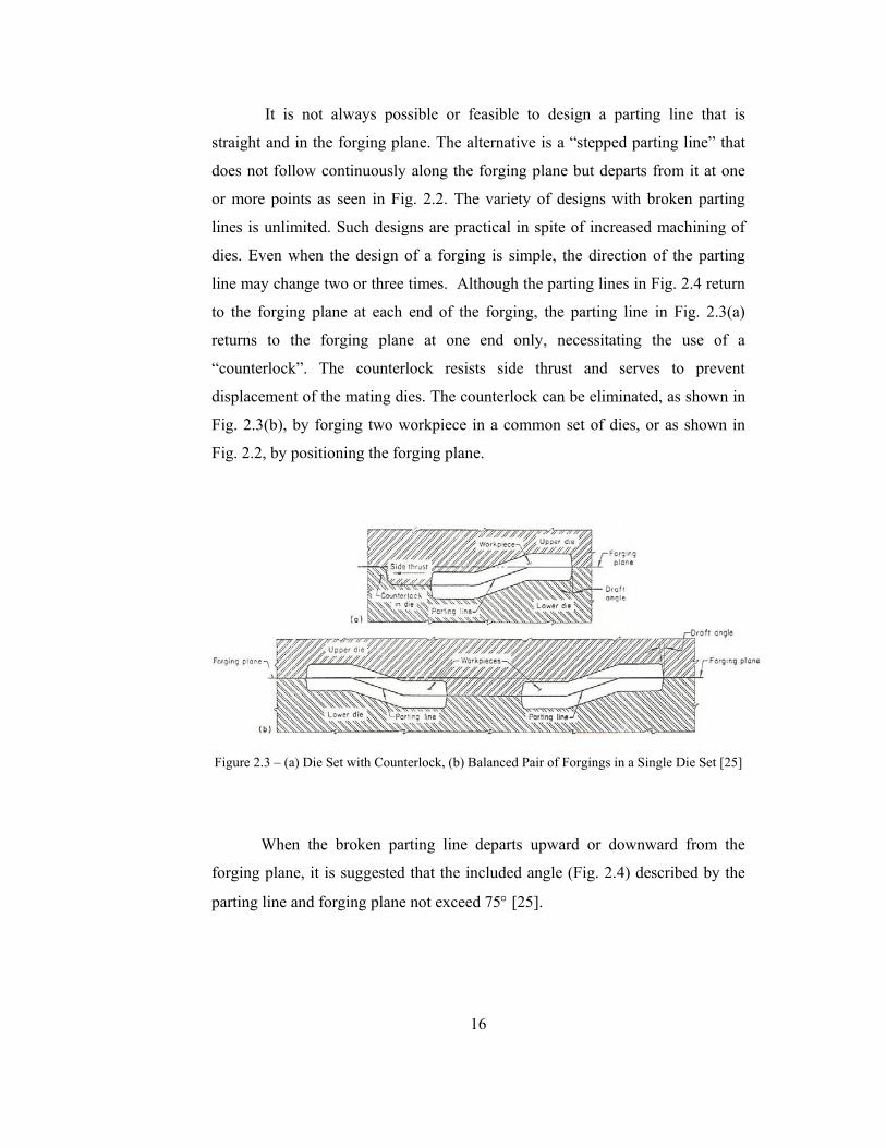
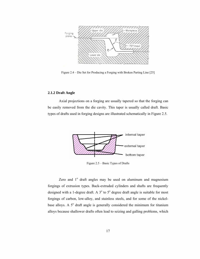


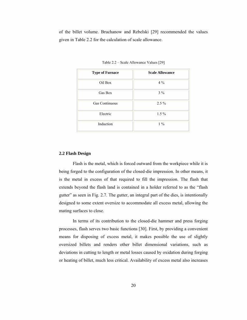
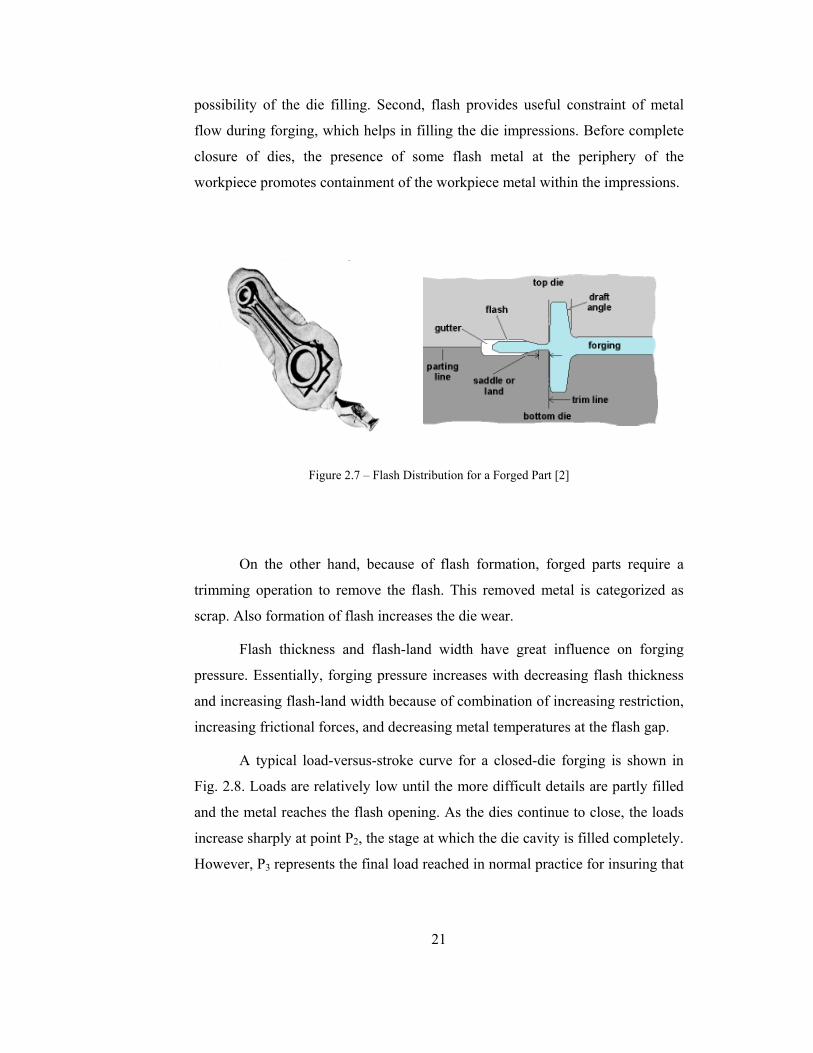


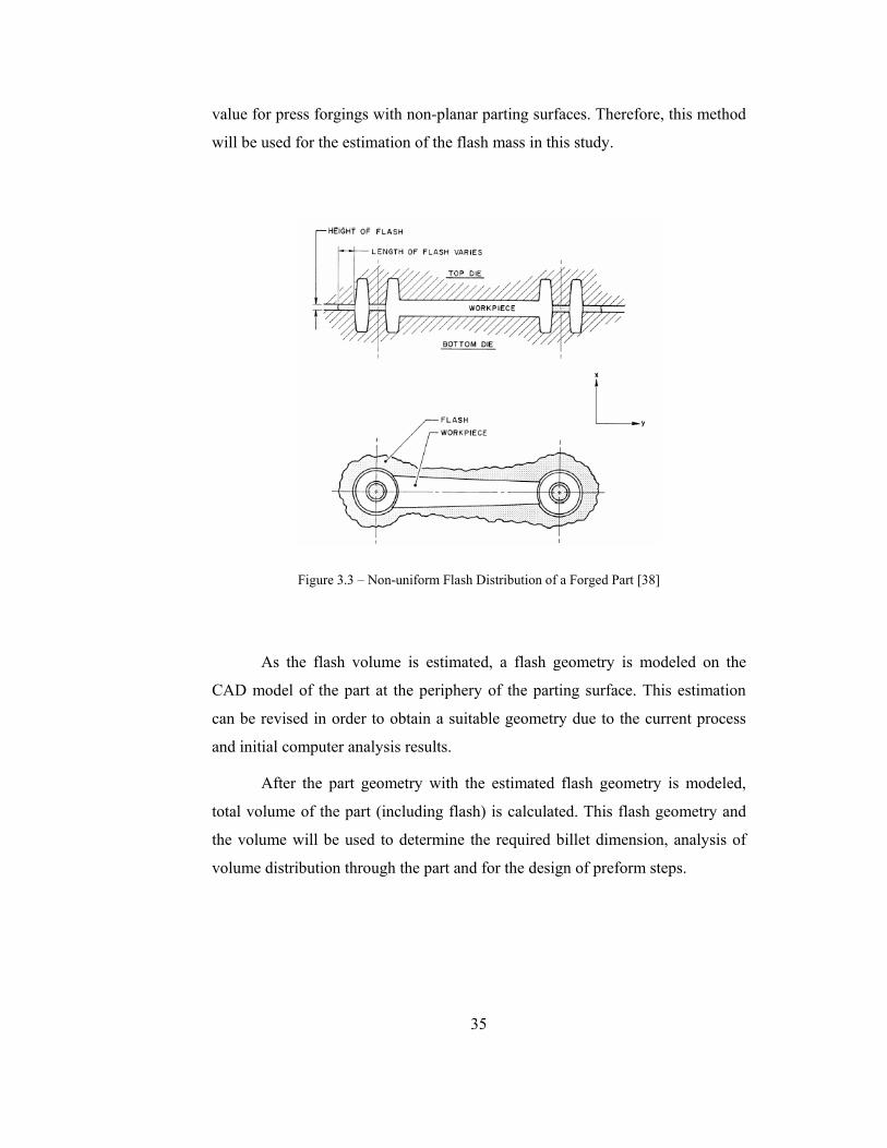
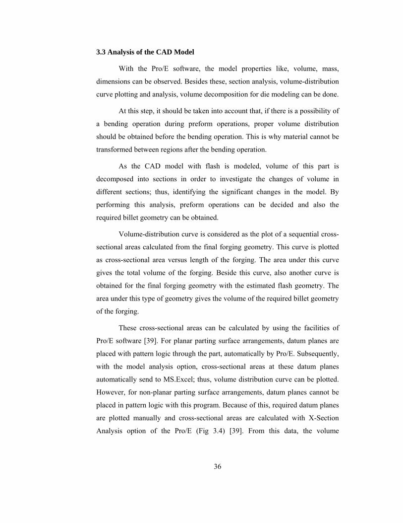
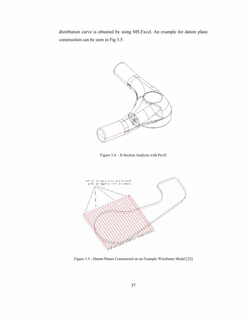


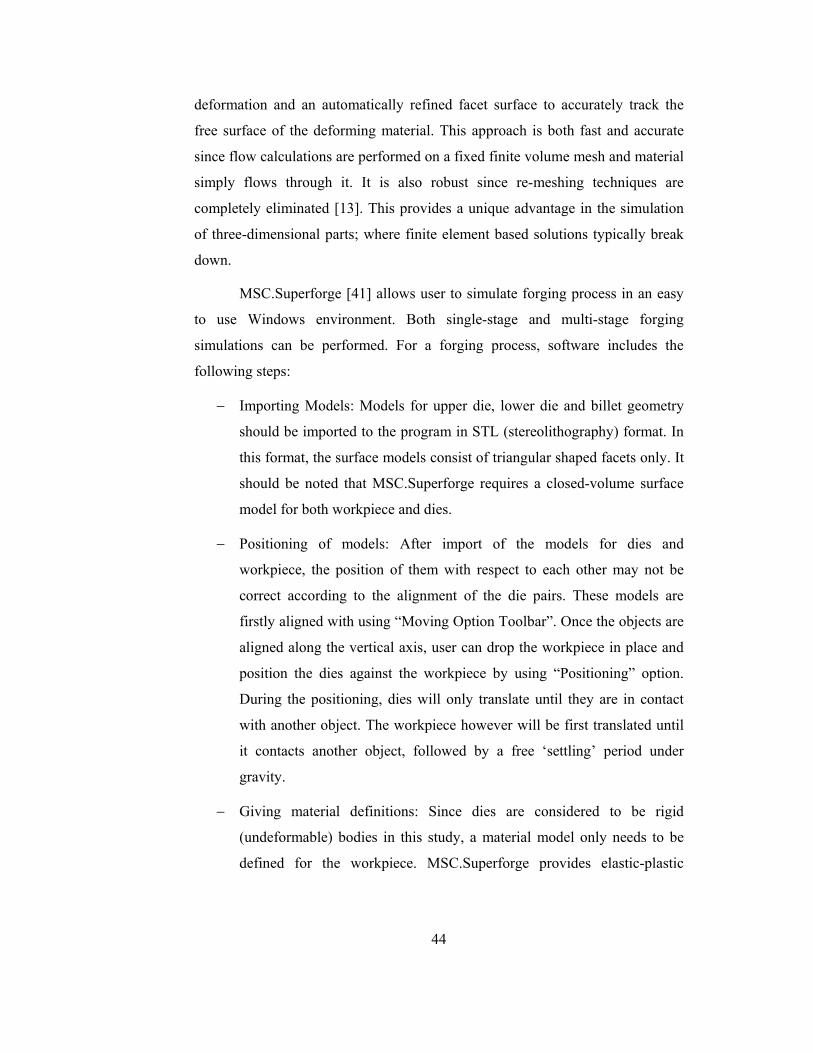


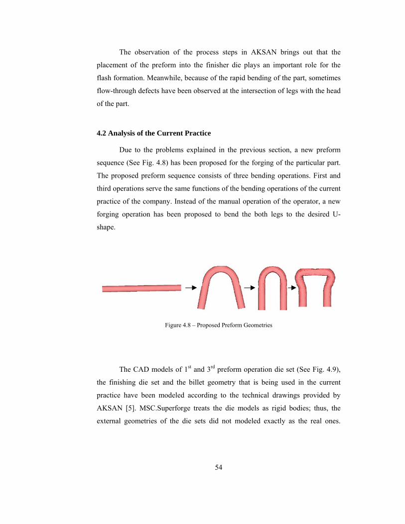

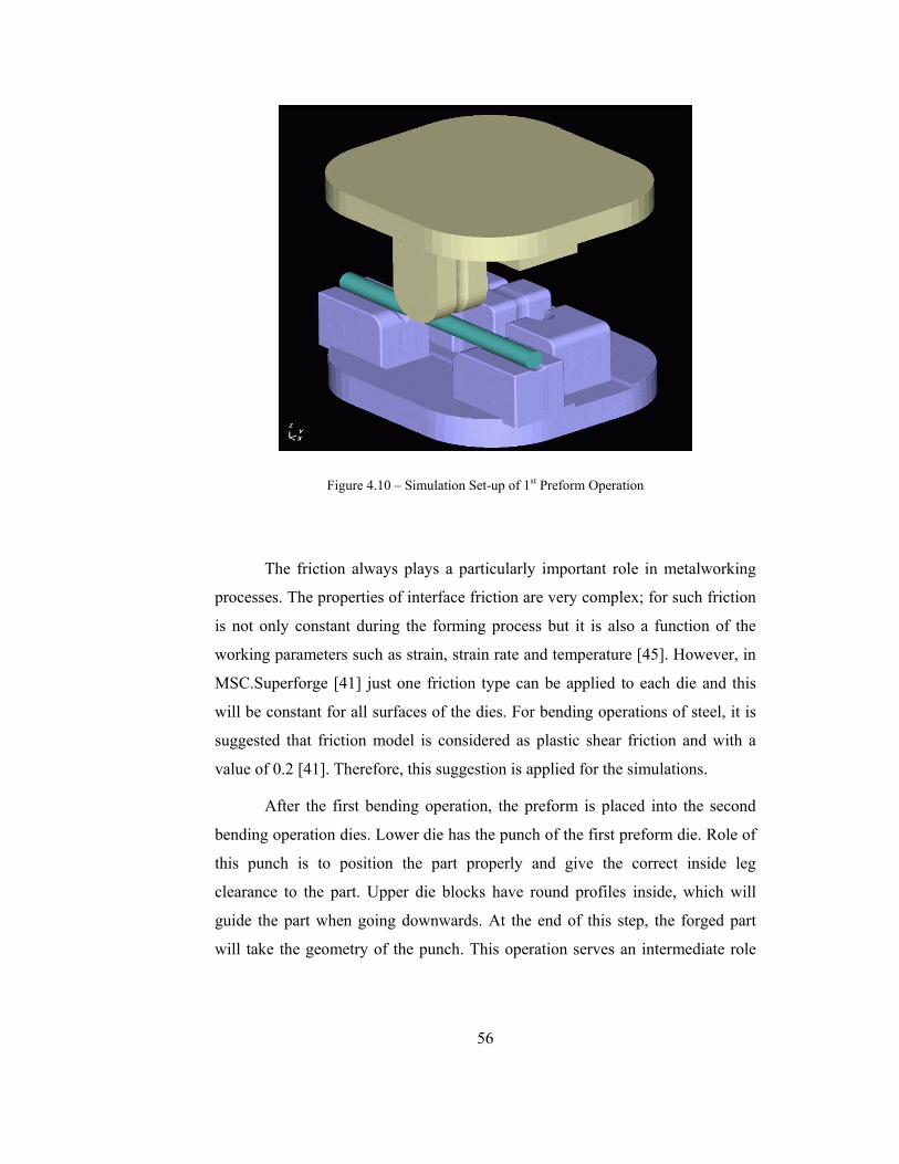


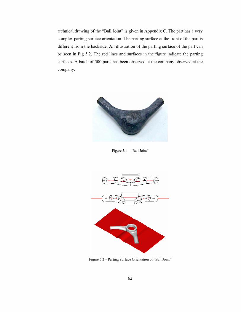

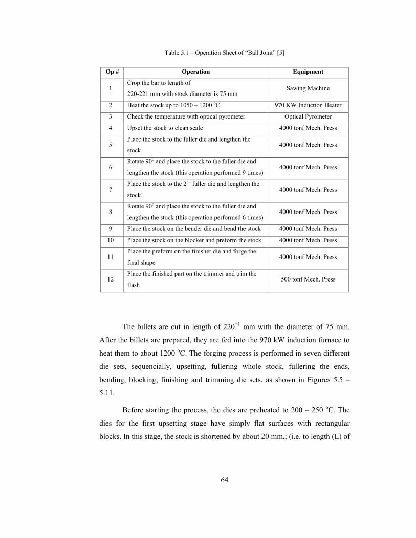


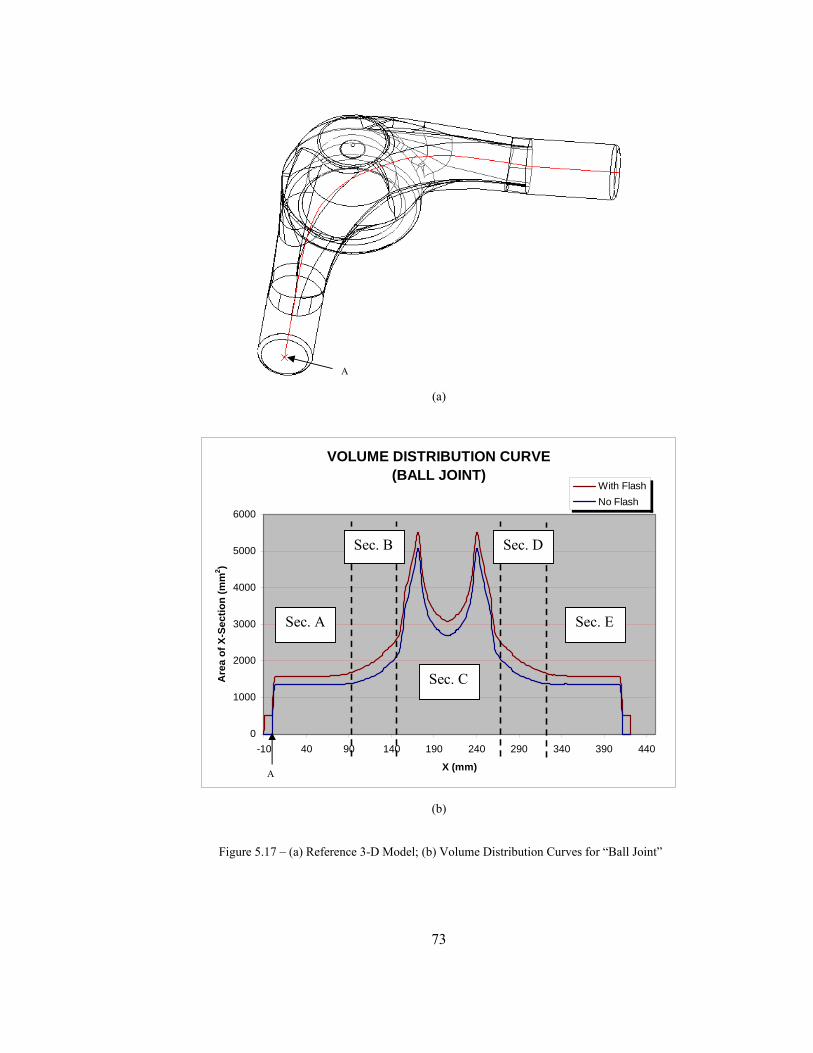


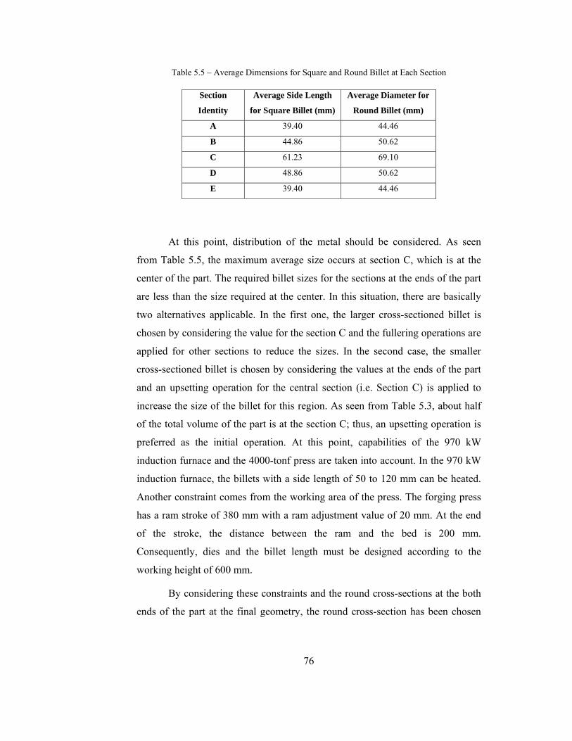


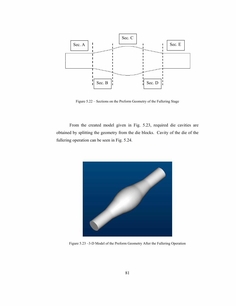


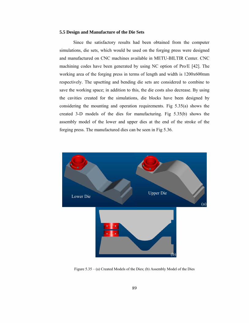


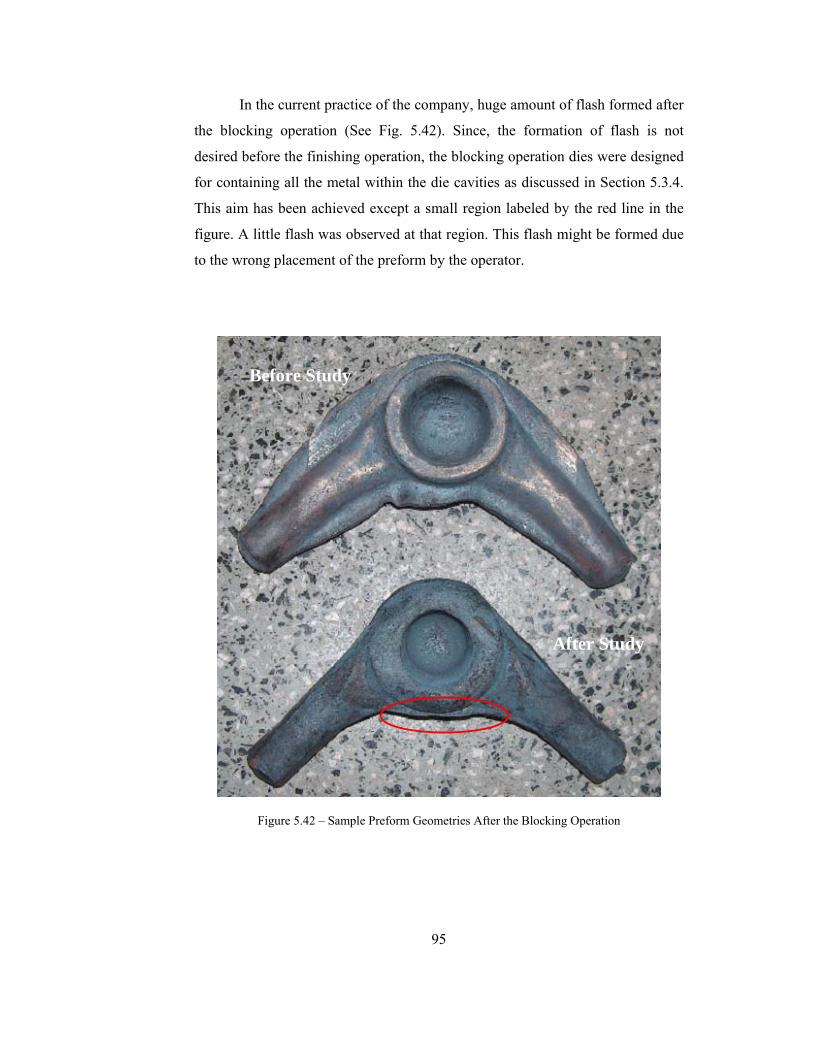


![1409 Preform design for forging and extrusion processes ...€¦ · forging shape and the desired final forging shape, based on sensitivity analysis [23]. Srikanth and Zabaras optimized](https://static.documents.pub/doc/80x56/60a4d3ee8c2eda5a685ad612/1409-preform-design-for-forging-and-extrusion-processes-forging-shape-and-the.jpg)


