Page 1
Zitholele Consulting Reg. No. 2000/000392/07
PO Box 6002 Halfway House 1685, South Africa Building 1, Maxwell Office Park, Magwa Crescent West c/o Allandale Road & Maxwell Drive, Waterfall City, Midrand T : 011 207 2060 F : 086 674 6121 E : [email protected]
Directors : Dr. R.G.M. Heath, S. Pillay, N. Rajasakran
REPORT
Preliminary Design Report for New Primary Sedimentation
Tanks at Bushkoppie Wastewater Treatment Works
Report No : 18057-45-Rep-001
Submitted to :
Johannesburg Water SOC Limited
17 Harrison Street Johannesburg
2001
4 March 2019 18057
Page 2
ii
ZITHOLELE CONSULTING
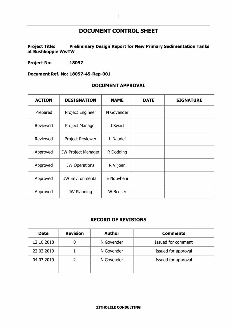
DOCUMENT CONTROL SHEET
Project Title: Preliminary Design Report for New Primary Sedimentation Tanks at Bushkoppie WwTW
Project No: 18057
Document Ref. No: 18057-45-Rep-001
DOCUMENT APPROVAL
ACTION DESIGNATION NAME DATE SIGNATURE
Prepared Project Engineer N Govender
Reviewed Project Manager J Swart
Reviewed Project Reviewer L Naude’
Approved JW Project Manager R Dodding
Approved JW Operations R Viljoen
Approved JW Environmental E Nduvheni
Approved JW Planning W Bedser
RECORD OF REVISIONS
Date Revision Author Comments
12.10.2018 0 N Govender Issued for comment
22.02.2019 1 N Govender Issued for approval
04.03.2019 2 N Govender Issued for approval
Page 3
4 March 2019 iii 18057
ZITHOLELE CONSULTING
EXECUTIVE SUMMARY
Johannesburg Water SOC Limited (JW) appointed Zitholele Consulting (ZC) to render
professional services for the addition of two new Primary Sedimentation Tanks (PSTs) at
Bushkoppie Wastewater Treatment Works (WwTW). The project is required to assist with the high
inflow and to give redundancy when maintenance of the PSTs is undertaken. During the project
inception phase the scope of the project was expanded to include construction of new PSTs and
the refurbishment of the existing PSTs and Fermenters. A project inception report was approved
by JW on the 2nd November 2018. Following the inception phase, the preliminary design is
required to evaluate various design options and select preferred design options that will be
developed during the detailed design phase of the project. This report documents the outcomes
from the preliminary design phase.
Scope of work
The scope of work for the project was divided into the refurbishment of existing infrastructure and
construction of new infrastructure.
• Refurbishment of existing infrastructure
A conditional assessment was undertaken by ZC to determine the condition of existing
infrastructure at the PST complex. The conditional assessment indicated that the existing PSTs
and Fermenters require civil and electro-mechanical refurbishment due to deterioration that has
occurred over time. The civil refurbishment primarily involves concrete and joint repair whilst the
mechanical refurbishment includes replacing broken mechanical equipment and refurbishing
installed equipment.
For both the Primary Sludge and Fermented Sludge Pump Stations various options were explored
to retrofit the existing Pump Stations with wet wells. This report documents a comparison of the
various design Options. The preferred Option for both the Primary Sludge and Fermented Sludge
Pump Stations entails retrofitting the existing Pump Stations with wet well configurations and
pumps that utilise a flooded suction.
• New PST infrastructure
Three design Options were evaluated for construction of the new PSTs. The three Options have
been outlined below:
1. Converting the existing Fermenters to PSTs
2. Positioning the new PSTs west of the existing PST complex
3. Positioning the new PSTs south of the existing PST complex
Page 4
4 March 2019 iv 18057
ZITHOLELE CONSULTING
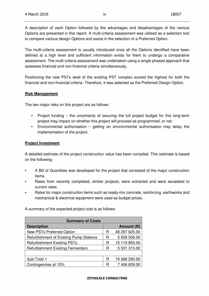
A description of each Option followed by the advantages and disadvantages of the various
Options are presented in this report. A multi-criteria assessment was utilised as a selection tool
to compare various design Options and assist in the selection of a Preferred Option.
The multi-criteria assessment is usually introduced once all the Options identified have been
defined at a high level and sufficient information exists for them to undergo a comparative
assessment. The multi-criteria assessment was undertaken using a single phased approach that
assesses financial and non-financial criteria simultaneously.
Positioning the new PSTs west of the existing PST complex scored the highest for both the
financial and non-financial criteria. Therefore, it was selected as the Preferred Design Option.
Risk Management
The two major risks on this project are as follows:
• Project funding – the uncertainty of securing the full project budget for this long-term
project may impact on whether this project will proceed as programmed, or not.
• Environmental authorisation – getting an environmental authorisation may delay the
implementation of the project.
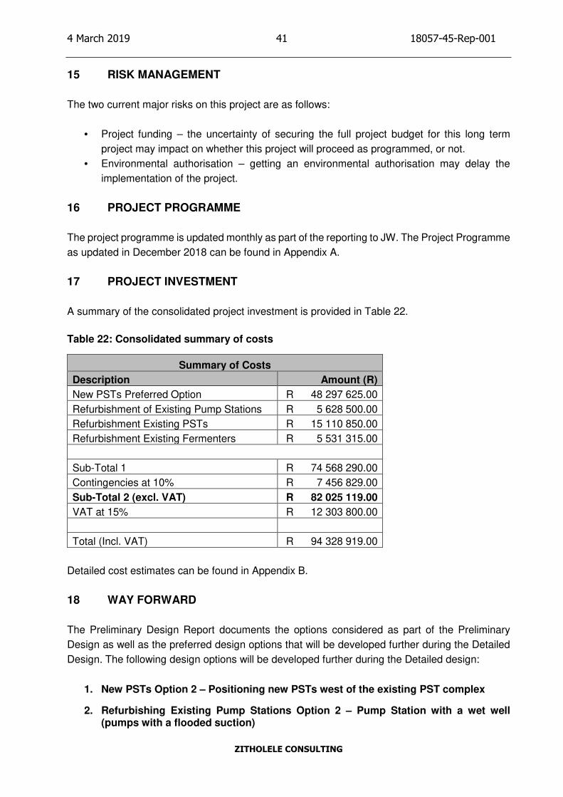
Project Investment
A detailed estimate of the project construction value has been compiled. This estimate is based
on the following:
• A Bill of Quantities was developed for the project that consisted of the major construction
items.
• Rates from recently completed, similar projects, were extracted and were escalated to
current rates.
• Rates for major construction items such as ready-mix concrete, reinforcing, earthworks and
mechanical & electrical equipment were used as budget prices.
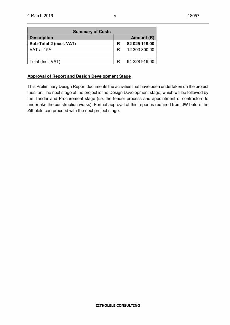
A summary of the expected project cost is as follows:
Summary of Costs
Description Amount (R)
New PSTs Preferred Option R 48 297 625.00
Refurbishment of Existing Pump Stations R 5 628 500.00
Refurbishment Existing PSTs R 15 110 850.00
Refurbishment Existing Fermenters R 5 531 315.00
Sub-Total 1 R 74 568 290.00
Contingencies at 10% R 7 456 829.00
Page 5
4 March 2019 v 18057
ZITHOLELE CONSULTING
Summary of Costs
Description Amount (R)
Sub-Total 2 (excl. VAT) R 82 025 119.00
VAT at 15% R 12 303 800.00
Total (Incl. VAT) R 94 328 919.00
Approval of Report and Design Development Stage
This Preliminary Design Report documents the activities that have been undertaken on the project
thus far. The next stage of the project is the Design Development stage, which will be followed by
the Tender and Procurement stage (i.e. the tender process and appointment of contractors to
undertake the construction works). Formal approval of this report is required from JW before the
Zitholele can proceed with the next project stage.
Page 6
4 March 2019 vi 18057
ZITHOLELE CONSULTING
TABLE OF CONTENTS
SECTION PAGE
1 INTRODUCTION ................................................................................................ 1
2 BACKGROUND .................................................................................................. 1
2.1 Details of appointment ..................................................................................... 1
2.2 Scope of work ................................................................................................. 1
2.3 Scope of services ............................................................................................ 2
2.4 Details of project team ..................................................................................... 2
3 PROJECT OBJECTIVE...................................................................................... 2
4 PROJECT INCEPTION ...................................................................................... 2
5 BASIS OF DESIGN ............................................................................................ 3
5.1 Design wastewater flows ................................................................................. 3
6 SITE DESCRIPTION .......................................................................................... 4
6.1 Location .......................................................................................................... 4
6.2 Topography, vegetation and site drainage ....................................................... 4
7 SITE INVESTIGATION – EXISTING INFRASTRUCTURE ............................... 4
7.1 Overview ......................................................................................................... 4
7.2 Civil Conditional Assessment .......................................................................... 5
PST 1 – 5 .......................................................................................... 5
PST division box ................................................................................ 6
Pump Stations ................................................................................... 6
Fermenters ........................................................................................ 7
7.3 Mechanical Conditional Assessment ............................................................... 8
PST 1 – 5 .......................................................................................... 8
PST division box ................................................................................ 9
Fermenters ........................................................................................ 9
Fermented Sludge Pump Station ..................................................... 10
8 REFURBISHMENT OF EXISTING INFRASTRUCTURE ................................ 10
8.1 PST Pump Stations ....................................................................................... 10
Option 1 – Pump Station with a wet well (pumps without a flooded suction) ............................................................................................ 10
8.1.1.1 Overview ......................................................................................... 10
8.1.1.2 Viability of Option 1 .......................................................................... 11
8.1.1.3 Cost Estimate – Option 1 ................................................................. 11
Option 2 – Pump Station with a wet well (pumps with a flooded suction) ........................................................................................................ 11
8.1.2.1 Overview ......................................................................................... 11
8.1.2.2 Viability of Option 2 .......................................................................... 12
8.1.2.3 Cost Estimate – Option 2 ................................................................. 12
Option 3 – Common Pump Station with a wet well ........................... 12
8.1.3.1 Overview ......................................................................................... 12
8.1.3.2 Viability of Option 3 .......................................................................... 12
8.1.3.3 Cost Estimate – Option 3 ................................................................. 12
Preferred Option .............................................................................. 13
8.2 PST 1 – 5 ...................................................................................................... 13
Overview ......................................................................................... 13
Cost Estimate – PST refurbishment ................................................. 14
8.3 Fermenters .................................................................................................... 14
Overview ......................................................................................... 14
Cost Estimate – Fermenter refurbishment ....................................... 15
8.4 Fermented Sludge Pump Station .................................................................. 15
Overview ......................................................................................... 15
Page 7
4 March 2019 vii 18057
ZITHOLELE CONSULTING
Viability ............................................................................................ 15
9 PRELIMINARY DESIGN OPTIONS – NEW PST 6 & 7 .................................. 16
9.1 Option 1 – Converting the existing Fermenters to PSTs ................................ 16
Overview ......................................................................................... 16
Site constraints ................................................................................ 16
Scope of work .................................................................................. 16
Viability of Option 1 .......................................................................... 17
Cost Estimate – Option 1 ................................................................. 18
9.2 Option 2 – Positioning new PSTs west of the existing PST complex ............. 18
Overview ......................................................................................... 18
Site constraints ................................................................................ 18
Scope of work .................................................................................. 19
Viability of Option 2 .......................................................................... 19
Cost Estimate – Option 2 ................................................................. 20
9.3 Option 3 – Positioning new PSTs south of the existing PST complex ............ 20
Overview ......................................................................................... 20
Site constraints ................................................................................ 21
Scope of work .................................................................................. 21
Viability of Option 3 .......................................................................... 21
Cost Estimate – Option 3 ................................................................. 22
9.4 Multi-criteria Assessment: New PSTs Option 1 – 3 ....................................... 23
Background ..................................................................................... 23
Defining the multi-criteria assessment ............................................. 24
Multi-criteria assessment weighting ................................................. 25
Multi-criteria assessment scoring ..................................................... 26
9.4.4.1 Financial component ....................................................................... 26
9.4.4.2 Non-financial component ................................................................. 26
9.4.4.3 Non-financial component ................................................................. 27
9.4.4.4 Combined scoring ............................................................................ 31
9.4.4.5 Sensitivity Analysis .......................................................................... 31
10 ELECTRICAL DESIGN .................................................................................... 32
10.1 Preferred Option – New PSTs west of the existing PST complex .................. 32
11 CONTROL AND INSTRUMENTATION ........................................................... 33
11.1 Scope of Work............................................................................................... 33
12 STRUCTURAL DESIGN .................................................................................. 36
12.1 General Design Philosophy ........................................................................... 36
Blasting During Construction ........................................................... 36
Concrete Cover to Reinforcement ................................................... 36
12.2 Liquid Retaining Structures ........................................................................... 36
Joints in Liquid Retaining Structures ................................................ 37
Codes of Practice ............................................................................ 37
Material Properties and Design Data ............................................... 37
General Loading, Analysis and Design of Liquid Retaining Structures ........................................................................................................ 37
12.3 Earth Retaining Structures ............................................................................ 38
Design Philosophy ........................................................................... 38
Codes of Practice ............................................................................ 39
Material Properties and Design Data ............................................... 39
12.4 Buildings ....................................................................................................... 39
Design Philosophy ........................................................................... 39
Codes of Practice ............................................................................ 39
Material Properties and Design Data ............................................... 40
13 ENVIRONMENTAL AUTHORISATION ........................................................... 40
14 HEALTH AND SAFETY.................................................................................... 40
Page 8
4 March 2019 viii 18057
ZITHOLELE CONSULTING
15 RISK MANAGEMENT ...................................................................................... 41
16 PROJECT PROGRAMME ............................................................................... 41
17 PROJECT INVESTMENT ................................................................................ 41
18 WAY FORWARD .............................................................................................. 41
LIST OF FIGURES
Figure 1: Aerial view of Bushkoppie WwTW ...................................................................... 4
Figure 2: Floor joints in PST 5 ........................................................................................... 5
Figure 3: Concrete Walls of PST 5 and box ....................................................................... 5
Figure 4: Deterioration of concrete inside PST division box ............................................... 6
Figure 5: Interior of Pump Stations servicing PST 1 -4 ...................................................... 7
Figure 6: Pump station servicing PST 5 ............................................................................. 7
Figure 7: Deteriorated concrete in the Fermenter launder and Fermenter Outlet Box ........ 8
Figure 8: Bridge and scraper mechanism for PST 4 .......................................................... 8
Figure 9: PST 5 – Bridge, stilling well & bridge .................................................................. 9
Figure 10: Sluice gates at the existing PST division box .................................................... 9
Figure 11: Fermenter bridge and scraper mechanism ..................................................... 10
Figure 12: Criteria utilised to select the preferred design option ...................................... 23
Figure 13: Process diagram for the multi-criteria assessment.......................................... 25
Figure 14: Proposed Control and Instrumentation installation .......................................... 33
Figure 15: C & I scope of work for new PSTs .................................................................. 35
LIST OF TABLES
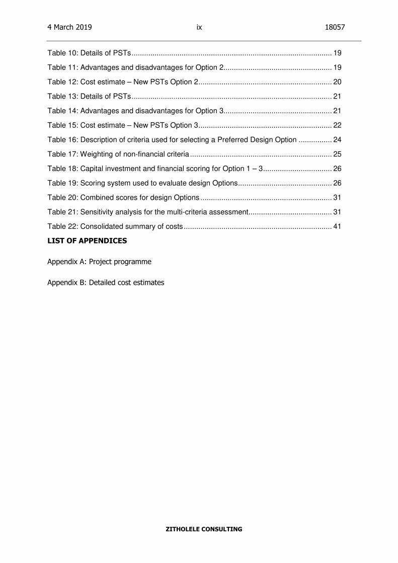
Table 1: Bushkoppie WwTW design flow rates .................................................................. 3
Table 2: Cost Estimate – Pump Station Refurbishment Option 1 ..................................... 11
Table 3: Cost Estimate – Pump Station Refurbishment Option 2 ..................................... 12
Table 4: Cost Estimate – Pump Station Refurbishment Option 3 ..................................... 12
Table 5: Cost estimate – PST refurbishment ................................................................... 14
Table 6: Cost estimate – Fermenter refurbishment .......................................................... 15
Table 7: Details of PSTs and Fermenters ........................................................................ 16
Table 8: Advantages and disadvantages for Option 1 ..................................................... 17
Table 9: Cost estimate – New PSTs Option 1 .................................................................. 18
Page 9
4 March 2019 ix 18057
ZITHOLELE CONSULTING
Table 10: Details of PSTs ................................................................................................ 19
Table 11: Advantages and disadvantages for Option 2.................................................... 19
Table 12: Cost estimate – New PSTs Option 2 ................................................................ 20
Table 13: Details of PSTs ................................................................................................ 21
Table 14: Advantages and disadvantages for Option 3.................................................... 21
Table 15: Cost estimate – New PSTs Option 3 ................................................................ 22
Table 16: Description of criteria used for selecting a Preferred Design Option ................ 24
Table 17: Weighting of non-financial criteria .................................................................... 25
Table 18: Capital investment and financial scoring for Option 1 – 3 ................................. 26
Table 19: Scoring system used to evaluate design Options ............................................. 26
Table 20: Combined scores for design Options ............................................................... 31
Table 21: Sensitivity analysis for the multi-criteria assessment ........................................ 31
Table 22: Consolidated summary of costs ....................................................................... 41
LIST OF APPENDICES
Appendix A: Project programme
Appendix B: Detailed cost estimates
Page 10
4 March 2019 x 18057
ZITHOLELE CONSULTING
LIST OF ACRONYMS
BA Basic Assessment
EIA Environmental Impact Assessment
JW Johannesburg Water SOC Limited
MCC Motor Control Centre
NEMA National Environmental Management Act
PST Primary Sedimentation Tank
WwTW Wastewater Treatment Works
ZC Zitholele Consulting
Page 11
4 March 2019 1 18057-45-Rep-001
ZITHOLELE CONSULTING
1 INTRODUCTION
The Bushkoppie Wastewater Treatment Works is situated on the Farm Misgund No 322-IQ in the
south west of the Greater Johannesburg Metropolitan area. The works receives wastewater from
the southern areas of Johannesburg via the South Eastern Outfall sewer and from the south
western areas of Johannesburg, Soweto and parts of Roodepoort through the Bushkoppie Phase
1 and 2 outfall sewers.
The current rated capacity of the works is 200 Mℓ/d and, according to information received from
JW’s planning department, the average daily flow to the works during the current 2018 calendar
year is 228 Mℓ/d. The works effluent is discharged to the Harrington Spruit which then discharges
into the Klip River.
Knight Piesold prepared a Capacity Report during 2014 on all JW WwTWs and the following was
stated in the report, regarding Bushkoppie:
On the basis of the limiting liquid and hydraulic capacities it is concluded that Bushkoppie Works
should be rated at a capacity of 200Mℓ/d. To beneficially utilize the liquid phase treatment capacity
available at Bushkoppie Works the limitations associated with the primary sedimentation tanks
need to be addressed so that the works could potentially be rerated at 240Mℓ/d.
JW appointed ZC to render professional services for the addition of two new PSTs at Bushkoppie
WwTW. The project is required to assist with the high inflow and to give redundancy when
maintenance of the PSTs is undertaken. During the project inception phase the scope of the
project was expanded to include construction of new PSTs and the refurbishment of the existing
PSTs and Fermenters. A project inception report was approved by JW on the 2nd November 2018.
Following the inception phase, the preliminary design is required to evaluate various design
options and select preferred design options that will be developed during the detailed design
phase of the project. This report documents the outcomes from the preliminary design phase.
2 BACKGROUND
2.1 Details of appointment
JW appointed ZC to provide professional services for the addition of two new PSTs at the
Bushkoppie WwTW. Works Order BWW1505 and a Project Charter, dated 16 March 2018, was
issued to Zitholele.
2.2 Scope of work
The scope of work entails the following:
• Refurbishment of the existing PSTs and equipment;
• Refurbishment of the existing Fermenters and equipment;
Page 12
4 March 2019 2 18057-45-Rep-001
ZITHOLELE CONSULTING
• Refurbishment of existing Primary Sludge Pump Stations and equipment;
• Refurbishment of existing Fermented Sludge Pump Station and equipment;
• Retrofitting existing Primary Sludge Pump Stations with wet wells;
• Retrofitting existing Fermented Sludge Pump Stations with wet wells; and
• Construction of two new PSTs, their Pump Station and associated pipework.
2.3 Scope of services
• Project Management
• Hydraulic Engineering
• Structural Engineering
• Civil Engineering
• Electrical Engineering
• Mechanical and Fire Engineering
• Control and Instrumentation (C & I) Engineering
• Quantity Surveying Services
2.4 Details of project team
Name Designation
Mr. Russel Dodding Project Manager – JW
Mr. William Bedser Project Planning – JW
Ms. Ronell Viljoen Operations – JW
Mr. Sugen Pillay Pr. Eng. Project Director – ZC
Mr. Jan Swart Pr. Eng. Lead Design Engineer (Civil and Mechanical) – ZC
Mr. Neil Govender Pr. Eng. Project Manager/ Design Engineer (Civil and Mechanical) – ZC
Mr. Douglas McDougall Design Engineer (Electrical and C & I) – ZC
Mr. Leon Naude Pr. Eng. External Project Reviewer – KWJV
Mr. E Nduvheni Environmental Manager – JW
3 PROJECT OBJECTIVE
JW’s objective is to construct two new PSTs and refurbish the existing PSTs and Fermenters
including all associated infrastructure. The project is being undertaken to assist with the high
inflow and give redundancy when maintenance is required. The retrofitting of wet wells at the
existing Primary Sludge and Fermented Sludge Pump Stations will enable easier maintenance.
4 PROJECT INCEPTION
A project inception report (Report No. 18057-42-Rep-001) was prepared for JW. One of the critical
aspects covered in the report was the scope of the project. The scope for this project (BWW 1505)
was expanded to include refurbishment of the existing PSTs, Fermenters and Pump Stations.
This scope was previously allocated to another project (BWW 1503).
Page 13
4 March 2019 3 18057-45-Rep-001
ZITHOLELE CONSULTING
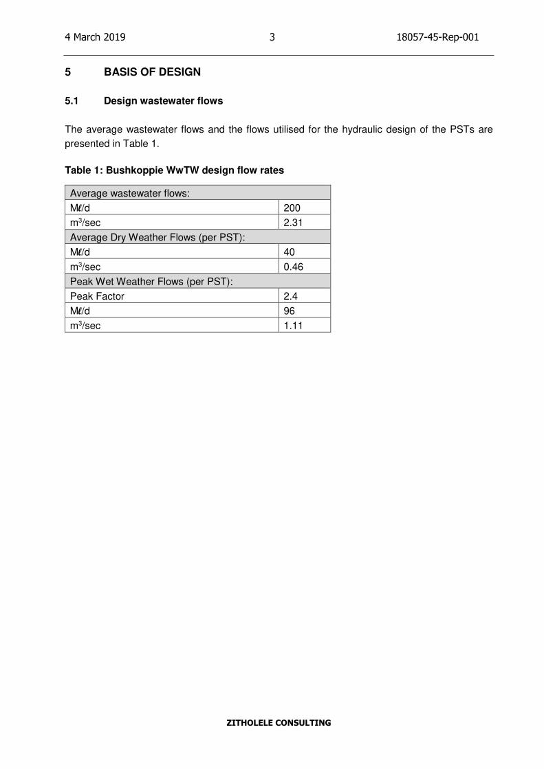
5 BASIS OF DESIGN
5.1 Design wastewater flows
The average wastewater flows and the flows utilised for the hydraulic design of the PSTs are
presented in Table 1.
Table 1: Bushkoppie WwTW design flow rates
Average wastewater flows:
Ml/d 200
m3/sec 2.31
Average Dry Weather Flows (per PST):
Ml/d 40
m3/sec 0.46
Peak Wet Weather Flows (per PST):
Peak Factor 2.4
Ml/d 96
m3/sec 1.11
Page 14
4 March 2019 4 18057-45-Rep-001
ZITHOLELE CONSULTING
6 SITE DESCRIPTION
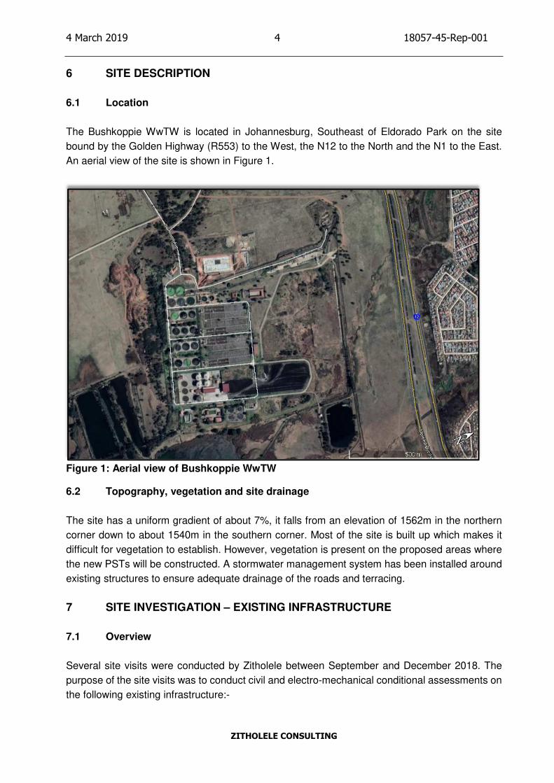
6.1 Location
The Bushkoppie WwTW is located in Johannesburg, Southeast of Eldorado Park on the site
bound by the Golden Highway (R553) to the West, the N12 to the North and the N1 to the East.
An aerial view of the site is shown in Figure 1.
Figure 1: Aerial view of Bushkoppie WwTW
6.2 Topography, vegetation and site drainage
The site has a uniform gradient of about 7%, it falls from an elevation of 1562m in the northern
corner down to about 1540m in the southern corner. Most of the site is built up which makes it
difficult for vegetation to establish. However, vegetation is present on the proposed areas where
the new PSTs will be constructed. A stormwater management system has been installed around
existing structures to ensure adequate drainage of the roads and terracing.
7 SITE INVESTIGATION – EXISTING INFRASTRUCTURE
7.1 Overview
Several site visits were conducted by Zitholele between September and December 2018. The
purpose of the site visits was to conduct civil and electro-mechanical conditional assessments on
the following existing infrastructure:-
Page 15
4 March 2019 5 18057-45-Rep-001
ZITHOLELE CONSULTING
• PST 1 – 5;
• Pump stations servicing PST 1 – 5;
• Fermenters; and
• Fermented Sludge Pump Station.
Note: PST 1 – 4 were not emptied due to the large amounts of sand that accumulated in those
PSTs. A conditional assessment was only conducted on PST 5. Since PST 1 – 4 are older and
more susceptible to deterioration, recommendations made for PST 1 – 4 will be based on the
assessment of PST 5.
7.2 Civil Conditional Assessment
PST 1 – 5
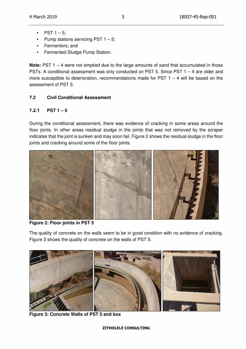
During the conditional assessment, there was evidence of cracking in some areas around the
floor joints. In other areas residual sludge in the joints that was not removed by the scraper
indicates that the joint is sunken and may soon fail. Figure 2 shows the residual sludge in the floor
joints and cracking around some of the floor joints.
Figure 2: Floor joints in PST 5
The quality of concrete on the walls seem to be in good condition with no evidence of cracking.
Figure 3 shows the quality of concrete on the walls of PST 5.
Figure 3: Concrete Walls of PST 5 and box
Page 16
4 March 2019 6 18057-45-Rep-001
ZITHOLELE CONSULTING
PST division box
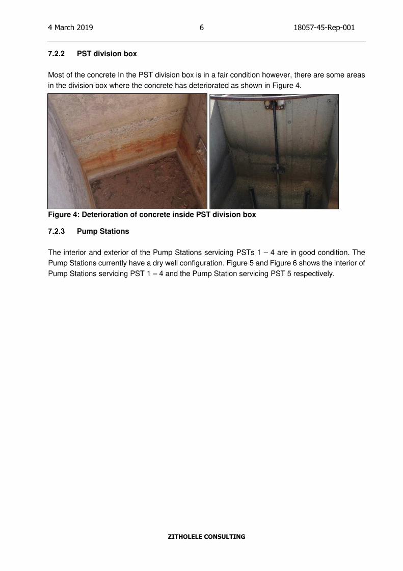
Most of the concrete In the PST division box is in a fair condition however, there are some areas
in the division box where the concrete has deteriorated as shown in Figure 4.
Figure 4: Deterioration of concrete inside PST division box
Pump Stations
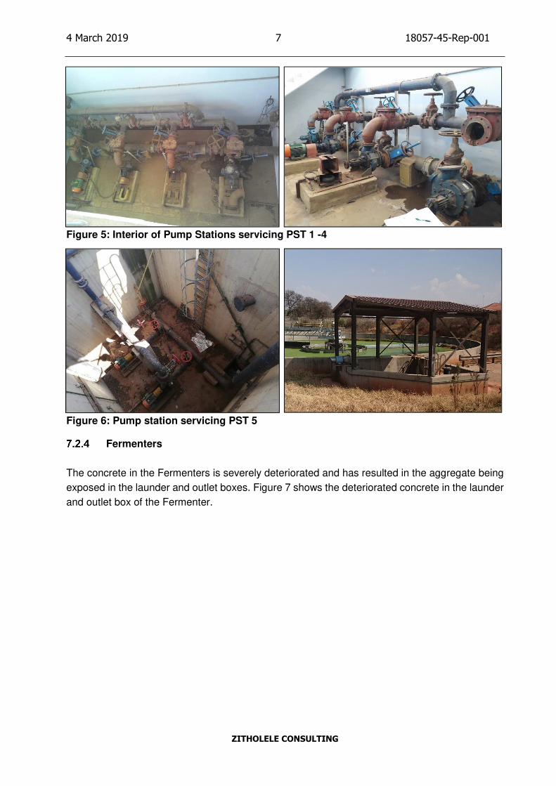
The interior and exterior of the Pump Stations servicing PSTs 1 – 4 are in good condition. The
Pump Stations currently have a dry well configuration. Figure 5 and Figure 6 shows the interior of
Pump Stations servicing PST 1 – 4 and the Pump Station servicing PST 5 respectively.
Page 17
4 March 2019 7 18057-45-Rep-001
ZITHOLELE CONSULTING
Figure 5: Interior of Pump Stations servicing PST 1 -4
Figure 6: Pump station servicing PST 5
Fermenters
The concrete in the Fermenters is severely deteriorated and has resulted in the aggregate being
exposed in the launder and outlet boxes. Figure 7 shows the deteriorated concrete in the launder
and outlet box of the Fermenter.
Page 18
4 March 2019 8 18057-45-Rep-001
ZITHOLELE CONSULTING
Figure 7: Deteriorated concrete in the Fermenter launder and Fermenter Outlet Box
7.3 Mechanical Conditional Assessment
PST 1 – 5
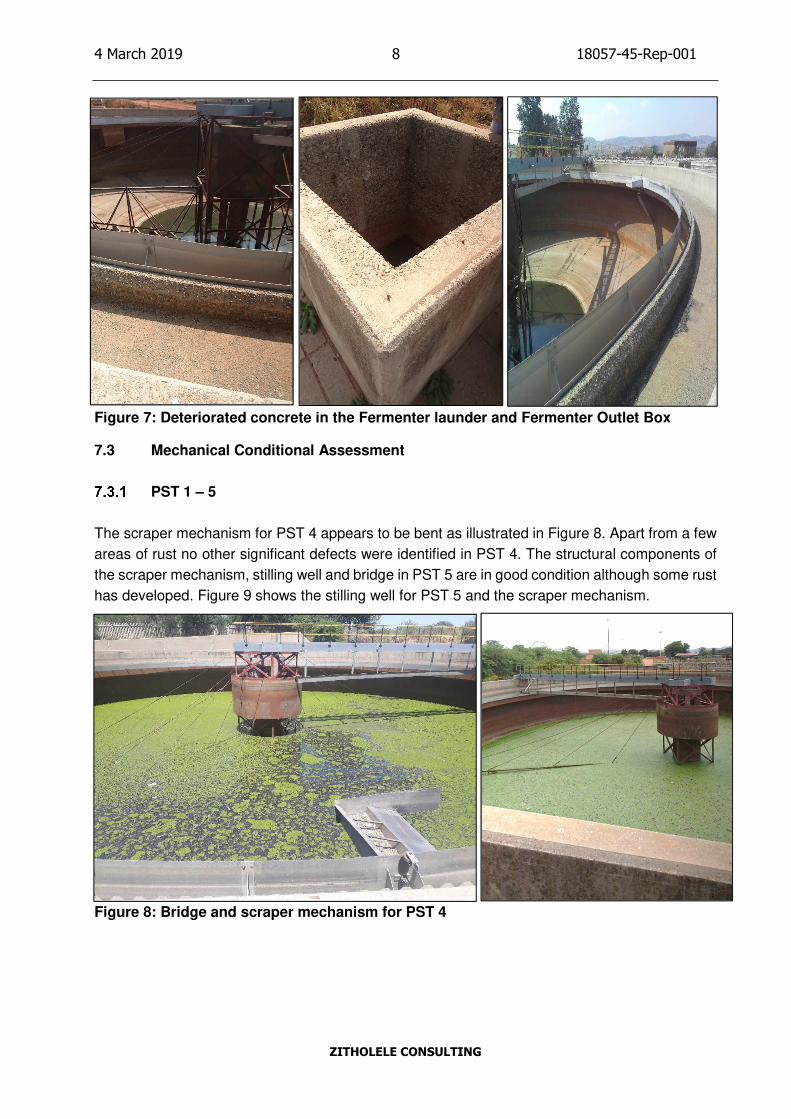
The scraper mechanism for PST 4 appears to be bent as illustrated in Figure 8. Apart from a few
areas of rust no other significant defects were identified in PST 4. The structural components of
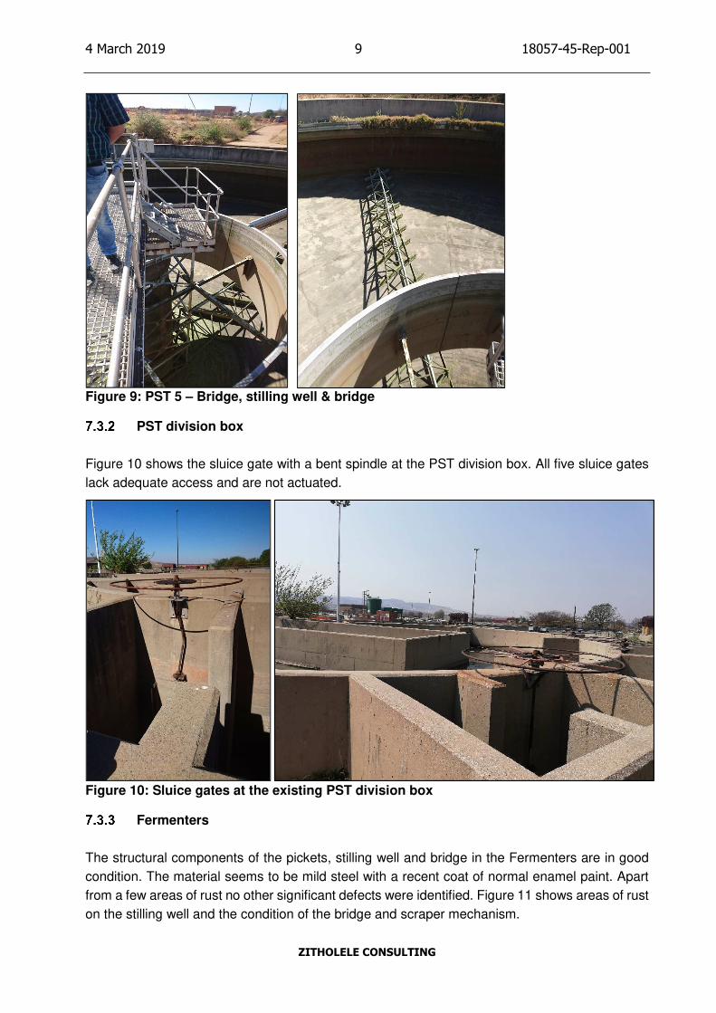
the scraper mechanism, stilling well and bridge in PST 5 are in good condition although some rust
has developed. Figure 9 shows the stilling well for PST 5 and the scraper mechanism.
Figure 8: Bridge and scraper mechanism for PST 4
Page 19
4 March 2019 9 18057-45-Rep-001
ZITHOLELE CONSULTING
Figure 9: PST 5 – Bridge, stilling well & bridge
PST division box
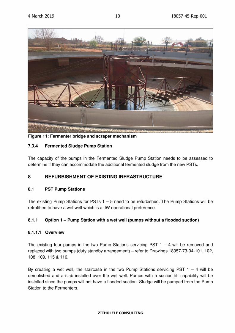
Figure 10 shows the sluice gate with a bent spindle at the PST division box. All five sluice gates
lack adequate access and are not actuated.
Figure 10: Sluice gates at the existing PST division box
Fermenters
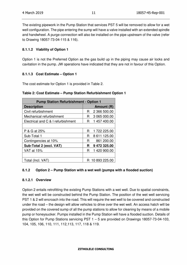
The structural components of the pickets, stilling well and bridge in the Fermenters are in good
condition. The material seems to be mild steel with a recent coat of normal enamel paint. Apart
from a few areas of rust no other significant defects were identified. Figure 11 shows areas of rust
on the stilling well and the condition of the bridge and scraper mechanism.
Page 20
4 March 2019 10 18057-45-Rep-001
ZITHOLELE CONSULTING
Figure 11: Fermenter bridge and scraper mechanism
Fermented Sludge Pump Station
The capacity of the pumps in the Fermented Sludge Pump Station needs to be assessed to
determine if they can accommodate the additional fermented sludge from the new PSTs.
8 REFURBISHMENT OF EXISTING INFRASTRUCTURE
8.1 PST Pump Stations
The existing Pump Stations for PSTs 1 – 5 need to be refurbished. The Pump Stations will be
retrofitted to have a wet well which is a JW operational preference.
Option 1 – Pump Station with a wet well (pumps without a flooded suction)
8.1.1.1 Overview
The existing four pumps in the two Pump Stations servicing PST 1 – 4 will be removed and
replaced with two pumps (duty standby arrangement) – refer to Drawings 18057-73-04-101, 102,
108, 109, 115 & 116.
By creating a wet well, the staircase in the two Pump Stations servicing PST 1 – 4 will be
demolished and a slab installed over the wet well. Pumps with a suction lift capability will be
installed since the pumps will not have a flooded suction. Sludge will be pumped from the Pump
Station to the Fermenters.
Page 21
4 March 2019 11 18057-45-Rep-001
ZITHOLELE CONSULTING
The existing pipework in the Pump Station that services PST 5 will be removed to allow for a wet
well configuration. The pipe entering the sump will have a valve installed with an extended spindle
and handwheel. A purge connection will also be installed on the pipe upstream of the valve (refer
to Drawing 18057-73-04-115 & 116).
8.1.1.2 Viability of Option 1
Option 1 is not the Preferred Option as the gas build up in the piping may cause air locks and
cavitation in the pump. JW operations have indicated that they are not in favour of this Option.
8.1.1.3 Cost Estimate – Option 1
The cost estimate for Option 1 is provided in Table 2.
Table 2: Cost Estimate – Pump Station Refurbishment Option 1
Pump Station Refurbishment - Option 1
Description Amount (R)
Civil refurbishment R 2 366 500.00
Mechanical refurbishment R 3 065 000.00
Electrical and C & I refurbishment R 1 457 400.00
P & G at 25% R 1 722 225.00
Sub-Total 1 R 8 611 125.00
Contingencies at 10% R 861 200.00
Sub-Total 2 (excl. VAT) R 9 472 325.00
VAT at 15% R 1 420 900.00
Total (Incl. VAT) R 10 893 225.00
Option 2 – Pump Station with a wet well (pumps with a flooded suction)
8.1.2.1 Overview
Option 2 entails retrofitting the existing Pump Stations with a wet well. Due to spatial constraints,
the wet well will be constructed behind the Pump Station. The position of the wet well servicing
PST 1 & 2 will encroach into the road. This will require the wet well to be covered and constructed
under the road – the design will allow vehicles to drive over the wet well. An access hatch will be
provided on the covered sump of all the pump stations to allow for cleaning by means of a mobile
pump or honeysucker. Pumps installed in the Pump Station will have a flooded suction. Details of
this Option for Pump Stations servicing PST 1 – 5 are provided on Drawings 18057-73-04-103,
104, 105, 106, 110, 111, 112,113, 117, 118 & 119.
Page 22
4 March 2019 12 18057-45-Rep-001
ZITHOLELE CONSULTING
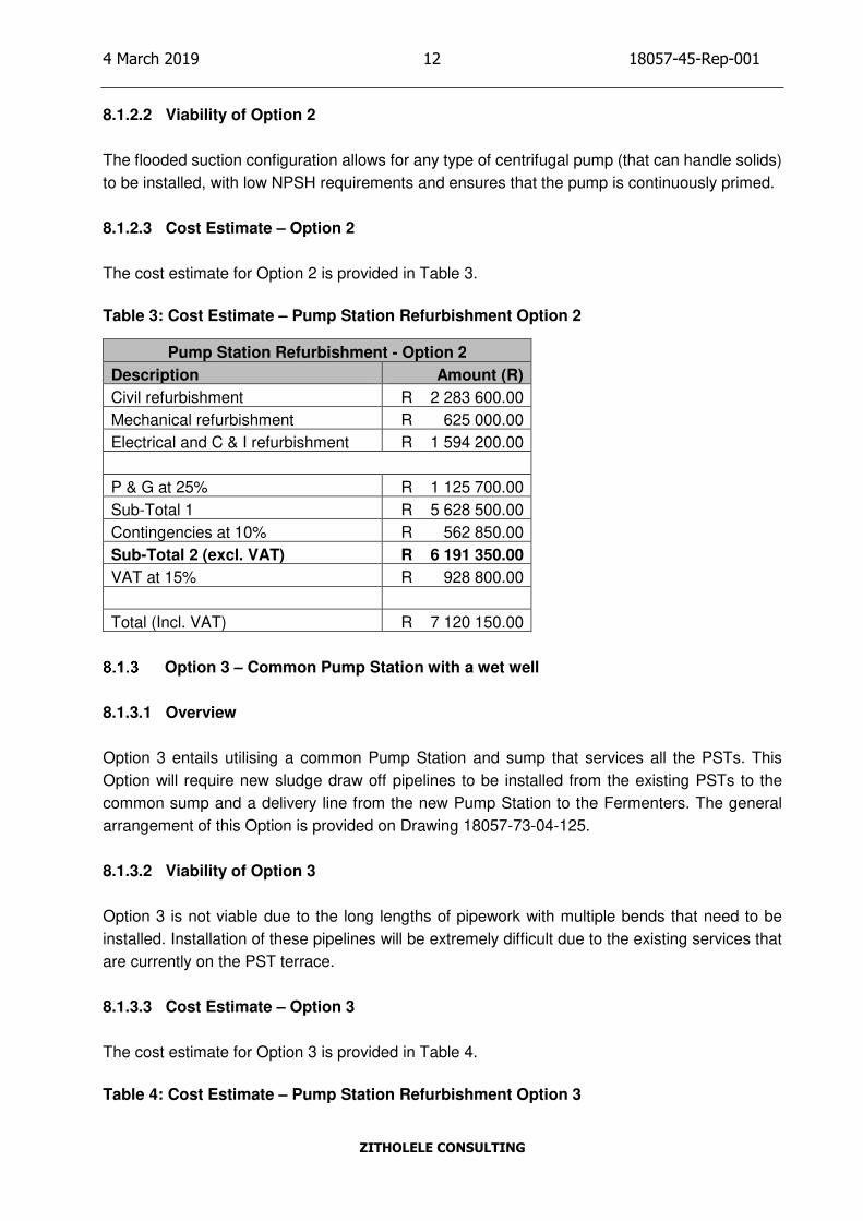
8.1.2.2 Viability of Option 2
The flooded suction configuration allows for any type of centrifugal pump (that can handle solids)
to be installed, with low NPSH requirements and ensures that the pump is continuously primed.
8.1.2.3 Cost Estimate – Option 2
The cost estimate for Option 2 is provided in Table 3.
Table 3: Cost Estimate – Pump Station Refurbishment Option 2
Pump Station Refurbishment - Option 2
Description Amount (R)
Civil refurbishment R 2 283 600.00
Mechanical refurbishment R 625 000.00
Electrical and C & I refurbishment R 1 594 200.00
P & G at 25% R 1 125 700.00
Sub-Total 1 R 5 628 500.00
Contingencies at 10% R 562 850.00
Sub-Total 2 (excl. VAT) R 6 191 350.00
VAT at 15% R 928 800.00
Total (Incl. VAT) R 7 120 150.00
Option 3 – Common Pump Station with a wet well
8.1.3.1 Overview
Option 3 entails utilising a common Pump Station and sump that services all the PSTs. This
Option will require new sludge draw off pipelines to be installed from the existing PSTs to the
common sump and a delivery line from the new Pump Station to the Fermenters. The general
arrangement of this Option is provided on Drawing 18057-73-04-125.
8.1.3.2 Viability of Option 3
Option 3 is not viable due to the long lengths of pipework with multiple bends that need to be
installed. Installation of these pipelines will be extremely difficult due to the existing services that
are currently on the PST terrace.
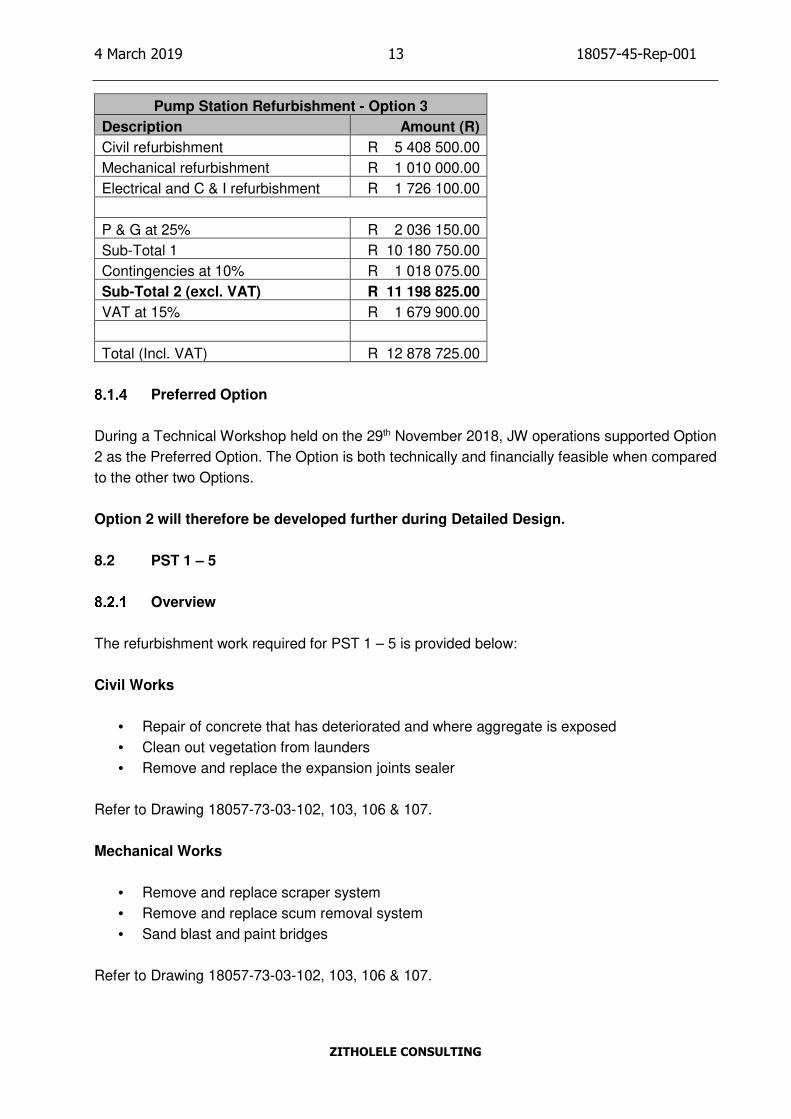
8.1.3.3 Cost Estimate – Option 3
The cost estimate for Option 3 is provided in Table 4.
Table 4: Cost Estimate – Pump Station Refurbishment Option 3
Page 23
4 March 2019 13 18057-45-Rep-001
ZITHOLELE CONSULTING
Pump Station Refurbishment - Option 3
Description Amount (R)
Civil refurbishment R 5 408 500.00
Mechanical refurbishment R 1 010 000.00
Electrical and C & I refurbishment R 1 726 100.00
P & G at 25% R 2 036 150.00
Sub-Total 1 R 10 180 750.00
Contingencies at 10% R 1 018 075.00
Sub-Total 2 (excl. VAT) R 11 198 825.00
VAT at 15% R 1 679 900.00
Total (Incl. VAT) R 12 878 725.00
Preferred Option
During a Technical Workshop held on the 29th November 2018, JW operations supported Option
2 as the Preferred Option. The Option is both technically and financially feasible when compared
to the other two Options.
Option 2 will therefore be developed further during Detailed Design.
8.2 PST 1 – 5
Overview
The refurbishment work required for PST 1 – 5 is provided below:
Civil Works
• Repair of concrete that has deteriorated and where aggregate is exposed
• Clean out vegetation from launders
• Remove and replace the expansion joints sealer
Refer to Drawing 18057-73-03-102, 103, 106 & 107.
Mechanical Works
• Remove and replace scraper system
• Remove and replace scum removal system
• Sand blast and paint bridges
Refer to Drawing 18057-73-03-102, 103, 106 & 107.
Page 24
4 March 2019 14 18057-45-Rep-001
ZITHOLELE CONSULTING
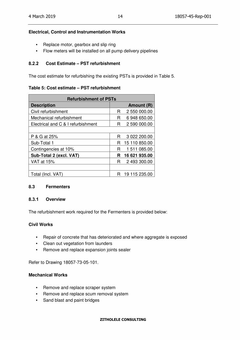
Electrical, Control and Instrumentation Works
• Replace motor, gearbox and slip ring
• Flow meters will be installed on all pump delivery pipelines
Cost Estimate – PST refurbishment
The cost estimate for refurbishing the existing PSTs is provided in Table 5.
Table 5: Cost estimate – PST refurbishment
Refurbishment of PSTs
Description Amount (R)
Civil refurbishment R 2 550 000.00
Mechanical refurbishment R 6 948 650.00
Electrical and C & I refurbishment R 2 590 000.00
P & G at 25% R 3 022 200.00
Sub-Total 1 R 15 110 850.00
Contingencies at 10% R 1 511 085.00
Sub-Total 2 (excl. VAT) R 16 621 935.00
VAT at 15% R 2 493 300.00
Total (Incl. VAT) R 19 115 235.00
8.3 Fermenters
Overview
The refurbishment work required for the Fermenters is provided below:
Civil Works
• Repair of concrete that has deteriorated and where aggregate is exposed
• Clean out vegetation from launders
• Remove and replace expansion joints sealer
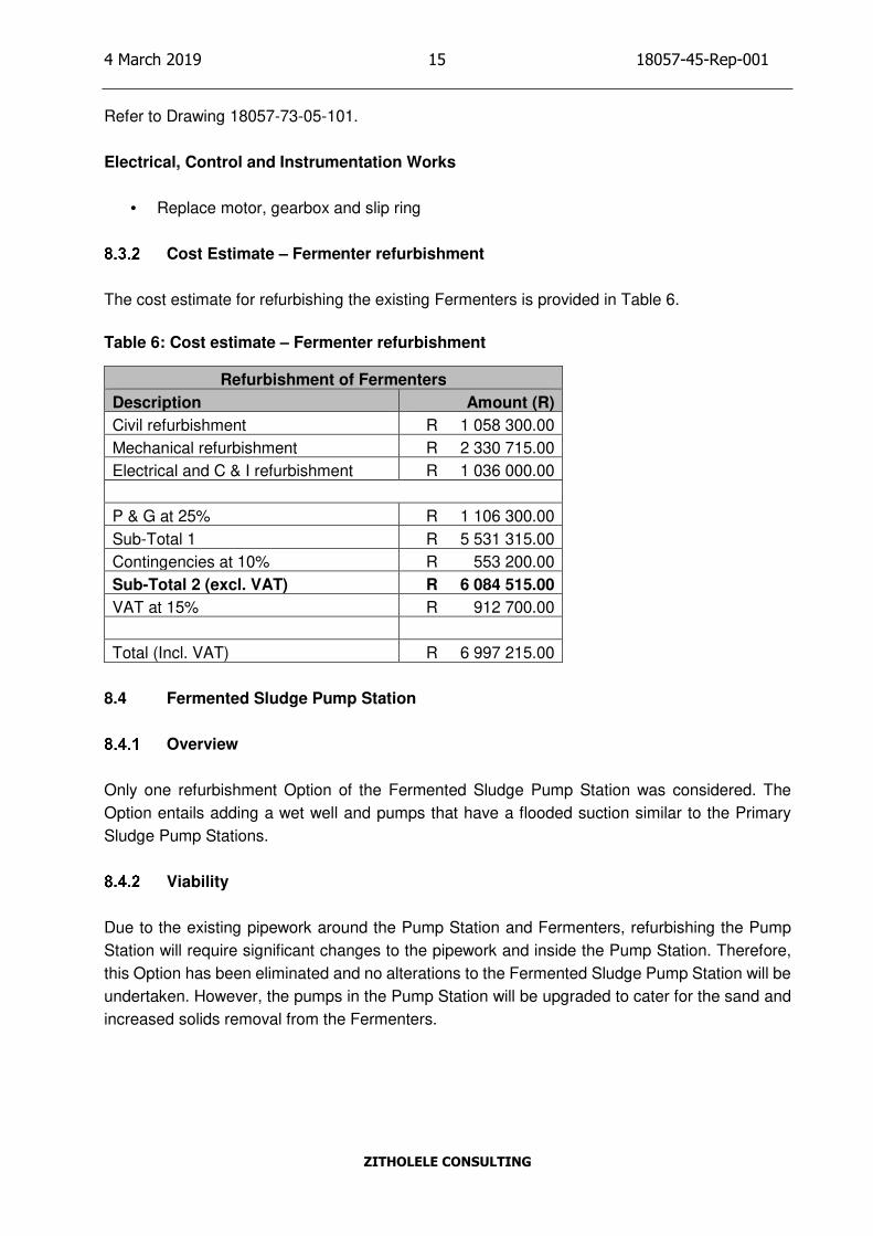
Refer to Drawing 18057-73-05-101.
Mechanical Works
• Remove and replace scraper system
• Remove and replace scum removal system
• Sand blast and paint bridges
Page 25
4 March 2019 15 18057-45-Rep-001
ZITHOLELE CONSULTING
Refer to Drawing 18057-73-05-101.
Electrical, Control and Instrumentation Works
• Replace motor, gearbox and slip ring
Cost Estimate – Fermenter refurbishment
The cost estimate for refurbishing the existing Fermenters is provided in Table 6.
Table 6: Cost estimate – Fermenter refurbishment
Refurbishment of Fermenters
Description Amount (R)
Civil refurbishment R 1 058 300.00
Mechanical refurbishment R 2 330 715.00
Electrical and C & I refurbishment R 1 036 000.00
P & G at 25% R 1 106 300.00
Sub-Total 1 R 5 531 315.00
Contingencies at 10% R 553 200.00
Sub-Total 2 (excl. VAT) R 6 084 515.00
VAT at 15% R 912 700.00
Total (Incl. VAT) R 6 997 215.00
8.4 Fermented Sludge Pump Station
Overview
Only one refurbishment Option of the Fermented Sludge Pump Station was considered. The
Option entails adding a wet well and pumps that have a flooded suction similar to the Primary
Sludge Pump Stations.
Viability
Due to the existing pipework around the Pump Station and Fermenters, refurbishing the Pump
Station will require significant changes to the pipework and inside the Pump Station. Therefore,
this Option has been eliminated and no alterations to the Fermented Sludge Pump Station will be
undertaken. However, the pumps in the Pump Station will be upgraded to cater for the sand and
increased solids removal from the Fermenters.
Page 26
4 March 2019 16 18057-45-Rep-001
ZITHOLELE CONSULTING
9 PRELIMINARY DESIGN OPTIONS – NEW PST 6 & 7
9.1 Option 1 – Converting the existing Fermenters to PSTs
Overview
Option 1 entails the conversion of the existing two Fermenters (25m diameter) into PSTs and the
construction of an additional 35m PST north of the existing Fermenters. Since the existing
Fermenters will be converted to PSTs, two new Fermenters (25m diameter) will be constructed
north of the lime dosing plant. A detailed layout of Option 1 is provided on Drawing 18057-73-01-
201.
Site constraints
The position of the new 35m diameter PST is constrained by the inlet channel on the west, the
access road on the east and the existing Fermenters on the south.
Scope of work
The scope of work for Option 1 is provided below:
• Refurbishment and conversion of the existing two Fermenters to PSTs
• Construction of a new 35m diameter PST (including feed and draw off pipework)
• Installation of a half bridge, centre supported with peripheral drive and half diameter
sludge scraper mechanism
• Conversion of the existing Fermented Sludge Pump Station into a Primary Sludge Pump
Station (including pipework)
• Construction of minor boxes
• Modifying the old PST division box to accommodate the feed pipeline to the 35m diameter
PST
• Construction of pipework:
o PSTs to the Biological Reactors
o PSTs to the Fermenters
o Fermenters to the Biological Reactors
o Fermenters to Thickened Sludge Pump Station Sump
• Construction of two new 25m diameter Fermenters (including feed and draw off pipework)
• Construction of a new Fermented Sludge Pump Station
• Construction of a new Fermenter Division Box
Table 7 provides details of the PSTs and Fermenters that will form part of Option 1.
Table 7: Details of PSTs and Fermenters
Page 27
4 March 2019 17 18057-45-Rep-001
ZITHOLELE CONSULTING
Unit Qty
Number of tanks No. 2 (Fermenters
converted to PSTs)
Diameter m 25
Side Water Depth m 4
Depth at centre m 7.775
Number of tanks No. 1 (New PST)
Diameter m 35
Side Water Depth m 4.2
Depth at centre m 8.65
Number of tanks No. 2 (New Fermenters)
Diameter m 25
Side Wall Liquid Depth m 4
Depth at centre m 7.775
Viability of Option 1
Table 8 provides the advantages and disadvantages for Option 1.
Table 8: Advantages and disadvantages for Option 1
Advantages Disadvantages
Flow division structure and pipework already
in place to new PSTs (existing Fermenters).
Extensive additional civil works for two new
Fermenters (including pipework and
construction of the two new Fermenters).
Few access constraints. Long pumping distance from PSTs to
Fermenters.
Incoming access road to the works does not
need to re-routed.
New PSTs (existing Fermenters) will need
new mechanical equipment to operate as
PSTs.
An additional 35m diameter PST and primary
sludge Pump Station will still have to be
constructed.
Screening of Primary Sludge to be relocated
to new Fermenters
Possibility of existing services on new PST
footprint.
High upflow rates for 25m diameter PSTs.
High cost.
Page 28
4 March 2019 18 18057-45-Rep-001
ZITHOLELE CONSULTING
Cost Estimate – Option 1
The cost estimate for Option 1 is provided in Table 9.
Table 9: Cost estimate – New PSTs Option 1
New Primary Sedimentation Tanks - Option 1
Description Amount (R)
Civil work R 34 071 700.00
Mechanical work R 3 240 000.00
Electrical and C & I work R 7 107 900.00
P & G at 25% R 11 104 900.00
Sub-Total 1 R 55 524 500.00
Contingencies at 10% R 5 552 450.00
Sub-Total 2 (excl. VAT) R 61 076 950.00
VAT at 15% R 9 161 600.00
Total (Incl. VAT) R 70 238 550.00
9.2 Option 2 – Positioning new PSTs west of the existing PST complex
Overview
Option 2 involves constructing two new 35m diameter PSTs to the west of the existing PST
complex. The feed to the PSTs will be taken upstream of the existing PST division box with an
overflow weir and a pipeline to a new division box that splits the flow to the two new PSTs. The
feed line to the PST division box is approximately 44m. To create adequate space for the
construction of the two new PSTs, the incoming access road needs to be re-routed. A significant
excavation will be required to create the terrace for the two new PSTs. A detailed layout of Option
2 is provided on Drawing 18057-73-01-301.
Site constraints
The position of the two new 35m diameter PSTs is constrained by the incoming access road on
the west and the existing PST complex on the east.
During the Technical Workshop held on the 29th November 2018, JW personnel advised that 5 x
185mm2 11kV underground cables would have to be relocated for this Option, as they are located
on the designated area for the new PSTs. The relocation of these cables will be part of the detailed
design, however, the proposal will be to isolate, cut, extend, reroute and terminate to the 11kV
circuit breakers in the 11kV substation.
Page 29
4 March 2019 19 18057-45-Rep-001
ZITHOLELE CONSULTING
Scope of work
The scope of work for Option 2 is provided below:
• Construction of two new 35m diameter PSTs (including feed and draw off pipework)
• Installation of half bridges on all PSTs, centre supported with peripheral drive and half
diameter sludge scraper mechanism
• Construction of a new flow division box
• Construction of a new Primary Sludge Pump Station
• Construction of a new terrace (including retaining walls)
• Modifying the existing stormwater system
• Demolishing and re-routing the existing access road
• Re-route 11kV cables
• Construction of pipework:
o PSTs to the existing effluent channel (which feeds the Biological Reactors)
o Primary Sludge Pump Station to the existing Fermenter division box
o Fermented Sludge Pump Station to the Biological Reactors (new larger pipe)
o Fermented Sludge Pump Station to the Thickened Sludge Pump Station Sump
(new larger pipe)
Table 10 provides details of the new PSTs that will form part of Option 2.
Table 10: Details of PSTs
Unit Qty
Number of tanks No. 2
Diameter m 35
Side Water Depth m 4
Depth at centre m 8.65
Viability of Option 2
Table 11 provides the advantages and disadvantages for Option 2.
Table 11: Advantages and disadvantages for Option 2
Advantages Disadvantages
Footprint reasonably clear of existing services
and pipework (only the 11kV cable needs to
be re-routed).
High retaining wall required at edge of new
terrace.
Relatively short lengths of pipework required
to tie into existing infrastructure.
Existing access roads and 11kV cables to be
re-routed.
Easy access between PSTs. Existing stormwater channel to be revised to a
pipe
Page 30
4 March 2019 20 18057-45-Rep-001
ZITHOLELE CONSULTING
Advantages Disadvantages
Earthworks should be straight forward as the
terrace is already cleared.
Odour concerns due to proximity to Admin
Building.
Construction can take place with minimal
disruption to the existing plant.
Low cost
Cost Estimate – Option 2
The cost estimate for Option 2 is provided in Table 12.
Table 12: Cost estimate – New PSTs Option 2
New Primary Sedimentation Tanks - Option 2
Description Amount (R)
Civil work R 31 481 900.00
Mechanical work R 1 010 000.00
Electrical and C & I work R 6 146 200.00
P & G at 25% R 9 659 525.00
Sub-Total 1 R 48 297 625.00
Contingencies at 10% R 4 829 800.00
Sub-Total 2 (excl. VAT) R 53 127 425.00
VAT at 15% R 7 969 200.00
Total (Incl. VAT) R 61 096 625.00
9.3 Option 3 – Positioning new PSTs south of the existing PST complex
Overview
Option 3 entails the construction of two new PSTs (35m diameter) south of the existing PST
complex. The existing access road will need to be re-routed around the new PSTs for access.
Similarly, the existing fence line will need to be demolished and installed around the new PST
terrace. The bulk earthworks for this Option may be challenging as a large rock outcrop is visible
on the proposed site.
Due to the location of the new PSTs, the feed pipeline that begins upstream of the existing PST
division box is approximately 167m. The Pump Station servicing PST 3 & 4 needs to be
demolished to enable the existing effluent channel to be extended toward the two new PSTs. The
demolished pump station will be constructed adjacent to the effluent channel and the associated
pipework from PST 3 & 4 will be modified accordingly. A detailed layout of Option 3 is provided
on Drawing 18057-73-01-401.
Page 31
4 March 2019 21 18057-45-Rep-001
ZITHOLELE CONSULTING
Site constraints
The position of the two new PSTs is constrained by the incoming access road in the north.
Scope of work
The scope of work for Option 3 is provided below:
• Construction of two new 35m diameter PSTs (including feed and draw off pipework)
• Installation of half bridges on all PSTs, centre supported with peripheral drive and half
diameter sludge scraper mechanism
• Construction of a new flow division box
• Construction of a new Primary Sludge Pump Station
• Construction of a new terrace
• Modifying the existing stormwater system
• Demolishing and re-routing the existing access road
• Construction of pipework:
o PSTs to the extended effluent channel (which feeds the Biological Reactors)
o PSTs to the above ground pipeline (which feeds the Fermenters)
o Fermenters to the Biological Reactors (new larger pipe)
o Fermenters to Thickened Sludge Pump Station Sump (new larger pipe)
• Demolish and construct Primary Sludge Pump Station servicing PST 3 & 4
• Modify sludge draw off pipework from PST 3 & 4
• Extend existing effluent channel
Table 13 provides details of the new PSTs that will form part of Option 3.
Table 13: Details of PSTs
Unit Qty
Number of tanks No. 2
Diameter m 35
Side Water Depth m 4
Depth at centre m 8.65
Viability of Option 3
Table 14 provides the advantages and disadvantages for Option 3.
Table 14: Advantages and disadvantages for Option 3
Advantages Disadvantages
Footprint is expected to be clear of existing
services and pipework.
Location in an environmentally sensitive area.
Page 32
4 March 2019 22 18057-45-Rep-001
ZITHOLELE CONSULTING
Advantages Disadvantages
Construction of access road required for new
PSTs.
Existing access road will have to be
demolished to allow for the concrete effluent
channel to be extended towards the new
PSTs.
Pump station servicing PST 3 & 4 will have to
be demolished. A new Pump Station will need
to be constructed. Pipework from PST 3 & 4 to
Pump Station needs to be modified
accordingly.
Long feed pipeline to new PSTs resulting in
less flow to the two new PSTs.
Access constraints between PSTs
High probability of encountering rock during
excavations.
Significant impact on existing works.
Cost Estimate – Option 3
The cost estimate for Option 3 is provided in Table 15.
Table 15: Cost estimate – New PSTs Option 3
New Primary Sedimentation Tanks - Option 3
Description Amount (R)
Civil work R 36 548 600.00
Mechanical work R 2 320 000.00
Electrical and C & I work R 8 081 700.00
P & G at 25% R 11 737 575.00
Sub-Total 1 R 58 687 875.00
Contingencies at 10% R 5 868 800.00
Sub-Total 2 (excl. VAT) R 64 556 675.00
VAT at 15% R 9 683 600.00
Total (Incl. VAT) R 74 240 275.00
Page 33
4 March 2019 23 18057-45-Rep-001
ZITHOLELE CONSULTING
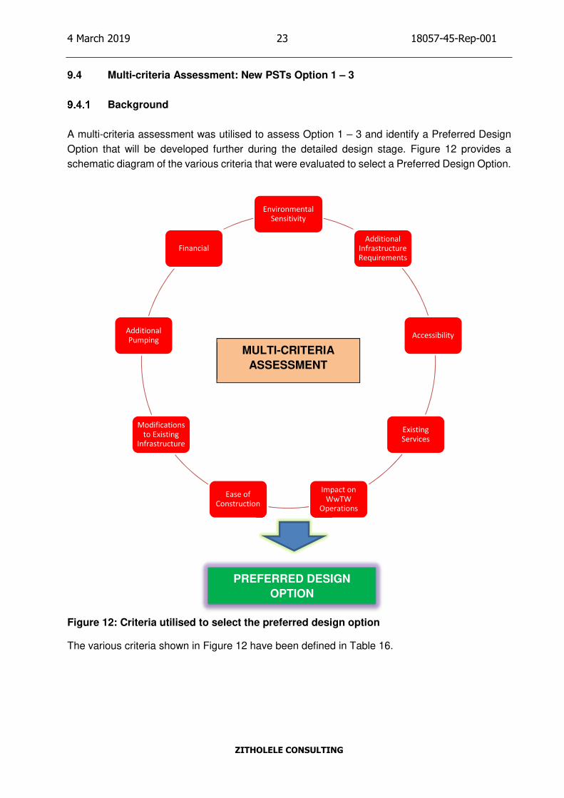
9.4 Multi-criteria Assessment: New PSTs Option 1 – 3
Background
A multi-criteria assessment was utilised to assess Option 1 – 3 and identify a Preferred Design
Option that will be developed further during the detailed design stage. Figure 12 provides a
schematic diagram of the various criteria that were evaluated to select a Preferred Design Option.
Figure 12: Criteria utilised to select the preferred design option
The various criteria shown in Figure 12 have been defined in Table 16.
MULTI-CRITERIA
ASSESSMENT
Environmental
Sensitivity
Additional
Infrastructure
Requirements
Accessibility
Existing
Services
Impact on
WwTW
Operations
Ease of
Construction
Modifications
to Existing
Infrastructure
Additional
Pumping
Financial
PREFERRED DESIGN
OPTION
Page 34
4 March 2019 24 18057-45-Rep-001
ZITHOLELE CONSULTING
Table 16: Description of criteria used for selecting a Preferred Design Option
Criteria Description
Environmental sensitivity The environmental sensitivity of the site under
consideration.
Additional infrastructure requirements The amount of additional infrastructure
required to implement the design Option.
Accessibility The ease of accessibility between PSTs and
infrastructure built as part of the design
Option.
Existing services The amount of existing services on the site
footprint that may render implementation of
the design Option difficult due to re-routing of
the existing services.
Impact on WwTW operations The impact that the design Option will have on
operations of the existing WwTW during
construction.
Ease of construction The relative ease of constructing a design
Option.
Modifications to existing infrastructure The amount of modifications required on
existing infrastructure when constructing the
design Option.
Additional pumping The additional pumping requirements when
the design Option is operational.
Financial The capital investment required to implement
the design Option.
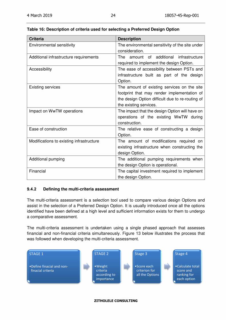
Defining the multi-criteria assessment
The multi-criteria assessment is a selection tool used to compare various design Options and
assist in the selection of a Preferred Design Option. It is usually introduced once all the options
identified have been defined at a high level and sufficient information exists for them to undergo
a comparative assessment.
The multi-criteria assessment is undertaken using a single phased approach that assesses
financial and non-financial criteria simultaneously. Figure 13 below illustrates the process that
was followed when developing the multi-criteria assessment.
STAGE 1
•Define finacial and non-
finacial criteria
STAGE 2
•Weight
criteria
according to
importance
Stage 3
•Score each
criterion for
all the Options
Stage 4
•Calculate total
score and
ranking for
each option
Page 35
4 March 2019 25 18057-45-Rep-001
ZITHOLELE CONSULTING
Figure 13: Process diagram for the multi-criteria assessment
The process illustrated in Figure 13 has been detailed below: -
Stage 1
• The financial and non-financial criteria was defined for all the design Options.
• The financial criteria consist solely of the capital investment required to implement the
project.
• The non-financial criteria ensured that technical, environmental and operational aspects
were considered.
Stage 2
• The weighting was based on the importance of each criterion. The more important criteria
were given a higher weighting whilst the less important criteria were given a lower
weighting. Section 9.4.3 describes the weighting process.
Stage 3
• The design Options were scored based on the criteria outlined Table 16.
Stage 4
• The total score for each Option was then calculated and are provided in Section 9.4.4.
Multi-criteria assessment weighting
The financial and non-financial criteria were weighted as follows:
Criteria Weighting
Financial 60%
Non-financial 40%
The financial component was weighted slightly higher since the cost of implementation is an
important consideration for JW due to lower expenditure on Bulk Wastewater projects in recent
years.
The weighting of the non-financial criteria were based on relative importance of each criterion.
The impact on the WwTW operations during construction, additional pumping requirements and
accessibility between the PST infrastructure were identified as the most important criteria.
Accordingly, they were weighted the highest amongst the non-financial criteria. A breakdown of
the weighting is provided in Table 17.
Table 17: Weighting of non-financial criteria
Page 36
4 March 2019 26 18057-45-Rep-001
ZITHOLELE CONSULTING
Criteria Weighting
Impact on WwTW operations 20%
Additional pumping 15%
Accessibility 15%
Existing services 10%
Environmental sensitivity 10%
Ease of construction 10%
Modifications to existing infrastructure 10%
Additional infrastructure requirements 10%
Total 100%
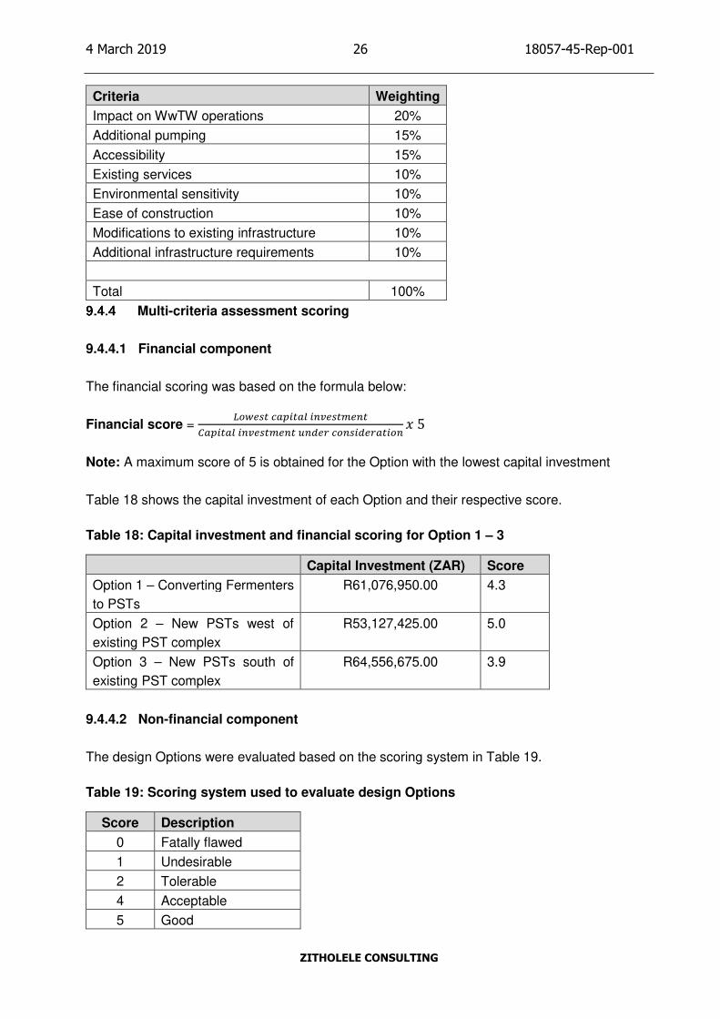
Multi-criteria assessment scoring
9.4.4.1 Financial component
The financial scoring was based on the formula below:
Financial score = ������ ���� � ������ �
���� � ������ � � ��� �� �������� � 5
Note: A maximum score of 5 is obtained for the Option with the lowest capital investment
Table 18 shows the capital investment of each Option and their respective score.
Table 18: Capital investment and financial scoring for Option 1 – 3
Capital Investment (ZAR) Score
Option 1 – Converting Fermenters
to PSTs
R61,076,950.00 4.3
Option 2 – New PSTs west of
existing PST complex
R53,127,425.00 5.0
Option 3 – New PSTs south of
existing PST complex
R64,556,675.00 3.9
9.4.4.2 Non-financial component
The design Options were evaluated based on the scoring system in Table 19.
Table 19: Scoring system used to evaluate design Options
Score Description
0 Fatally flawed
1 Undesirable
2 Tolerable
4 Acceptable
5 Good
Page 37
4 March 2019 27 18057-45-Rep-001
ZITHOLELE CONSULTING
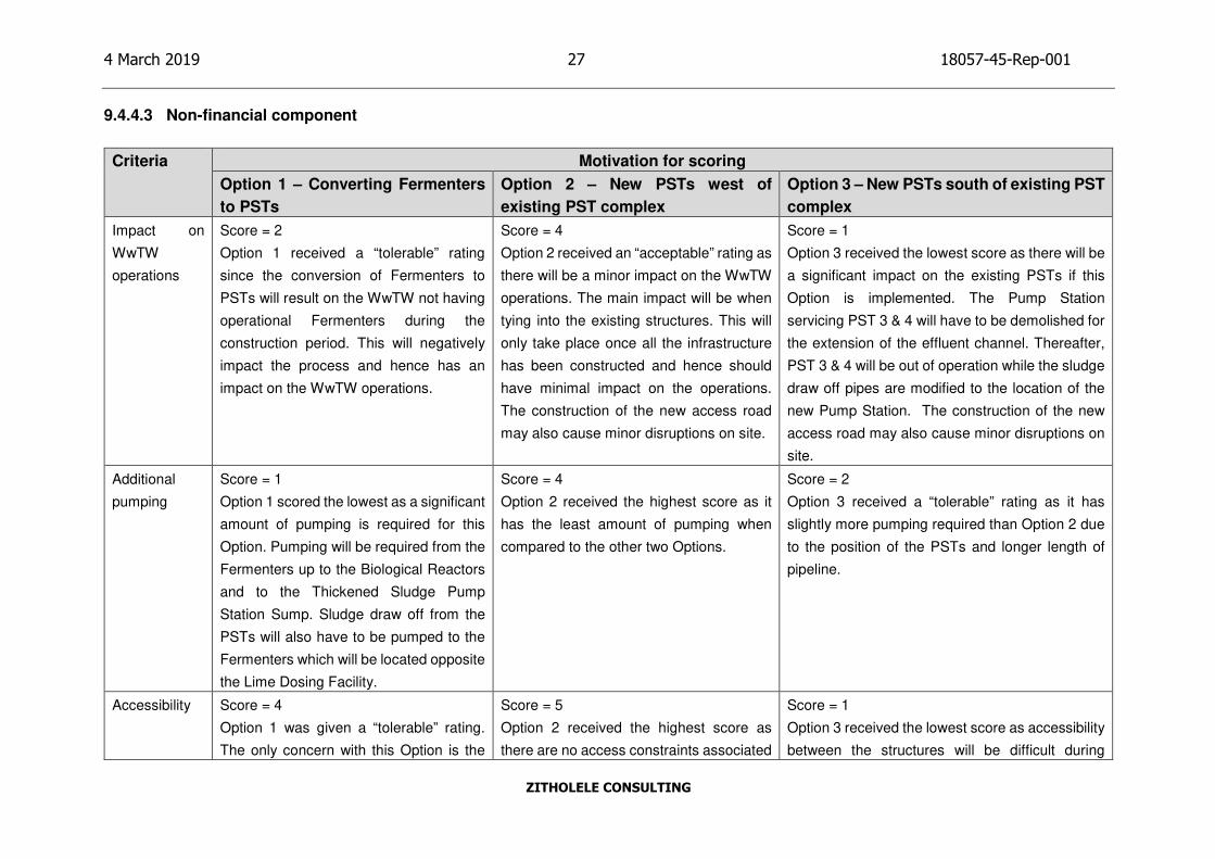
9.4.4.3 Non-financial component
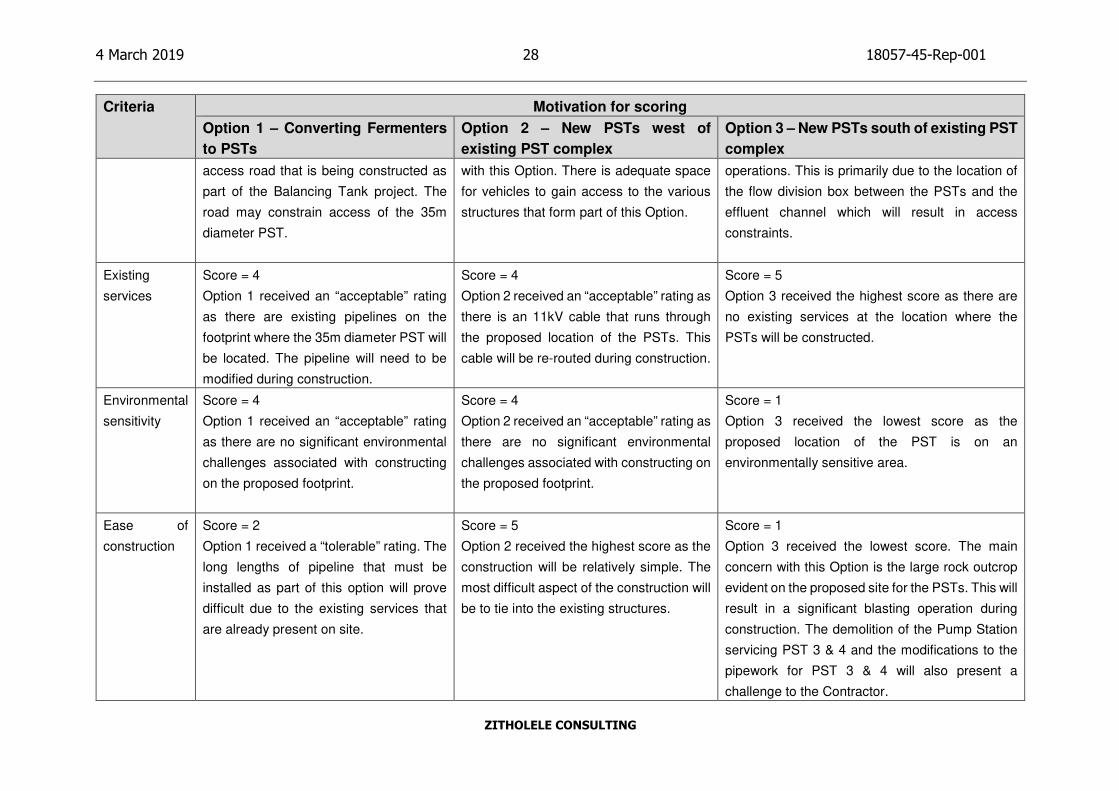
Criteria Motivation for scoring
Option 1 – Converting Fermenters
to PSTs
Option 2 – New PSTs west of
existing PST complex
Option 3 – New PSTs south of existing PST
complex
Impact on
WwTW
operations
Score = 2
Option 1 received a “tolerable” rating
since the conversion of Fermenters to
PSTs will result on the WwTW not having
operational Fermenters during the
construction period. This will negatively
impact the process and hence has an
impact on the WwTW operations.
Score = 4
Option 2 received an “acceptable” rating as
there will be a minor impact on the WwTW
operations. The main impact will be when
tying into the existing structures. This will
only take place once all the infrastructure
has been constructed and hence should
have minimal impact on the operations.
The construction of the new access road
may also cause minor disruptions on site.
Score = 1
Option 3 received the lowest score as there will be
a significant impact on the existing PSTs if this
Option is implemented. The Pump Station
servicing PST 3 & 4 will have to be demolished for
the extension of the effluent channel. Thereafter,
PST 3 & 4 will be out of operation while the sludge
draw off pipes are modified to the location of the
new Pump Station. The construction of the new
access road may also cause minor disruptions on
site.
Additional
pumping
Score = 1
Option 1 scored the lowest as a significant
amount of pumping is required for this
Option. Pumping will be required from the
Fermenters up to the Biological Reactors
and to the Thickened Sludge Pump
Station Sump. Sludge draw off from the
PSTs will also have to be pumped to the
Fermenters which will be located opposite
the Lime Dosing Facility.
Score = 4
Option 2 received the highest score as it
has the least amount of pumping when
compared to the other two Options.
Score = 2
Option 3 received a “tolerable” rating as it has
slightly more pumping required than Option 2 due
to the position of the PSTs and longer length of
pipeline.
Accessibility Score = 4
Option 1 was given a “tolerable” rating.
The only concern with this Option is the
Score = 5
Option 2 received the highest score as
there are no access constraints associated
Score = 1
Option 3 received the lowest score as accessibility
between the structures will be difficult during
Page 38
4 March 2019 28 18057-45-Rep-001
ZITHOLELE CONSULTING
Criteria Motivation for scoring
Option 1 – Converting Fermenters
to PSTs
Option 2 – New PSTs west of
existing PST complex
Option 3 – New PSTs south of existing PST
complex
access road that is being constructed as
part of the Balancing Tank project. The
road may constrain access of the 35m
diameter PST.
with this Option. There is adequate space
for vehicles to gain access to the various
structures that form part of this Option.
operations. This is primarily due to the location of
the flow division box between the PSTs and the
effluent channel which will result in access
constraints.
Existing
services
Score = 4
Option 1 received an “acceptable” rating
as there are existing pipelines on the
footprint where the 35m diameter PST will
be located. The pipeline will need to be
modified during construction.
Score = 4
Option 2 received an “acceptable” rating as
there is an 11kV cable that runs through
the proposed location of the PSTs. This
cable will be re-routed during construction.
Score = 5
Option 3 received the highest score as there are
no existing services at the location where the
PSTs will be constructed.
Environmental
sensitivity
Score = 4
Option 1 received an “acceptable” rating
as there are no significant environmental
challenges associated with constructing
on the proposed footprint.
Score = 4
Option 2 received an “acceptable” rating as
there are no significant environmental
challenges associated with constructing on
the proposed footprint.
Score = 1
Option 3 received the lowest score as the
proposed location of the PST is on an
environmentally sensitive area.
Ease of
construction
Score = 2
Option 1 received a “tolerable” rating. The
long lengths of pipeline that must be
installed as part of this option will prove
difficult due to the existing services that
are already present on site.
Score = 5
Option 2 received the highest score as the
construction will be relatively simple. The
most difficult aspect of the construction will
be to tie into the existing structures.
Score = 1
Option 3 received the lowest score. The main
concern with this Option is the large rock outcrop
evident on the proposed site for the PSTs. This will
result in a significant blasting operation during
construction. The demolition of the Pump Station
servicing PST 3 & 4 and the modifications to the
pipework for PST 3 & 4 will also present a
challenge to the Contractor.
Page 39
4 March 2019 29 18057-45-Rep-001
ZITHOLELE CONSULTING
Criteria Motivation for scoring
Option 1 – Converting Fermenters
to PSTs
Option 2 – New PSTs west of
existing PST complex
Option 3 – New PSTs south of existing PST
complex
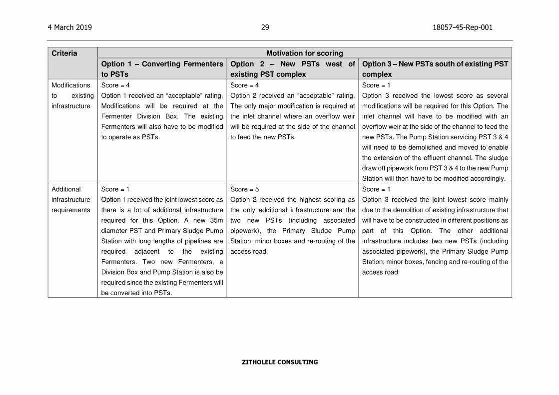
Modifications
to existing
infrastructure
Score = 4
Option 1 received an “acceptable” rating.
Modifications will be required at the
Fermenter Division Box. The existing
Fermenters will also have to be modified
to operate as PSTs.
Score = 4
Option 2 received an “acceptable” rating.
The only major modification is required at
the inlet channel where an overflow weir
will be required at the side of the channel
to feed the new PSTs.
Score = 1
Option 3 received the lowest score as several
modifications will be required for this Option. The
inlet channel will have to be modified with an
overflow weir at the side of the channel to feed the
new PSTs. The Pump Station servicing PST 3 & 4
will need to be demolished and moved to enable
the extension of the effluent channel. The sludge
draw off pipework from PST 3 & 4 to the new Pump
Station will then have to be modified accordingly.
Additional
infrastructure
requirements
Score = 1
Option 1 received the joint lowest score as
there is a lot of additional infrastructure
required for this Option. A new 35m
diameter PST and Primary Sludge Pump
Station with long lengths of pipelines are
required adjacent to the existing
Fermenters. Two new Fermenters, a
Division Box and Pump Station is also be
required since the existing Fermenters will
be converted into PSTs.
Score = 5
Option 2 received the highest scoring as
the only additional infrastructure are the
two new PSTs (including associated
pipework), the Primary Sludge Pump
Station, minor boxes and re-routing of the
access road.
Score = 1
Option 3 received the joint lowest score mainly
due to the demolition of existing infrastructure that
will have to be constructed in different positions as
part of this Option. The other additional
infrastructure includes two new PSTs (including
associated pipework), the Primary Sludge Pump
Station, minor boxes, fencing and re-routing of the
access road.
Page 40
4 March 2019 30 18057-45-Rep-001
ZITHOLELE CONSULTING
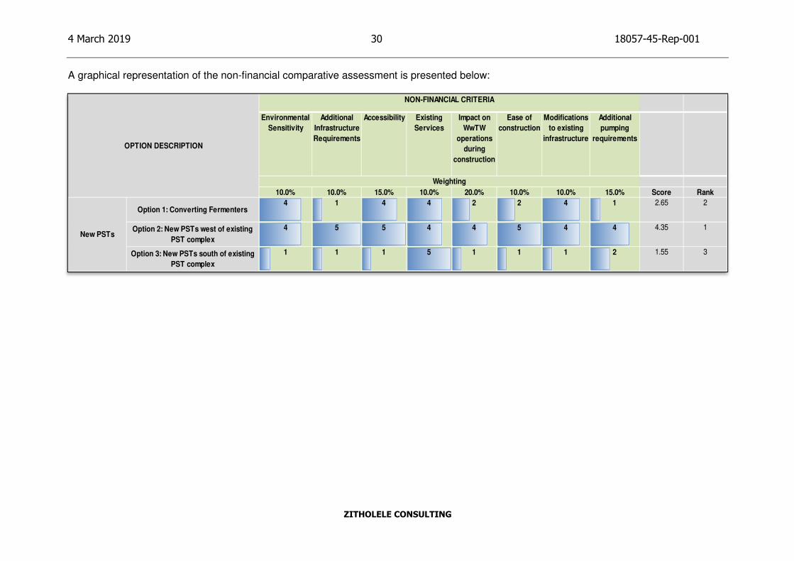
A graphical representation of the non-financial comparative assessment is presented below:
Environmental
Sensitivity
Additional
Infrastructure
Requirements
Accessibility Existing
Services
Impact on
WwTW
operations
during
construction
Ease of
construction
Modifications
to existing
infrastructure
Additional
pumping
requirements
10.0% 10.0% 15.0% 10.0% 20.0% 10.0% 10.0% 15.0% Score Rank
Option 1: Converting Fermenters4 1 4 4 2 2 4 1 2.65 2
Option 2: New PSTs west of existing
PST complex
4 5 5 4 4 5 4 4 4.35 1
Option 3: New PSTs south of existing
PST complex
1 1 1 5 1 1 1 2 1.55 3
NON-FINANCIAL CRITERIA
Weighting
OPTION DESCRIPTION
New PSTs
Page 41
4 March 2019 31 18057-45-Rep-001
ZITHOLELE CONSULTING
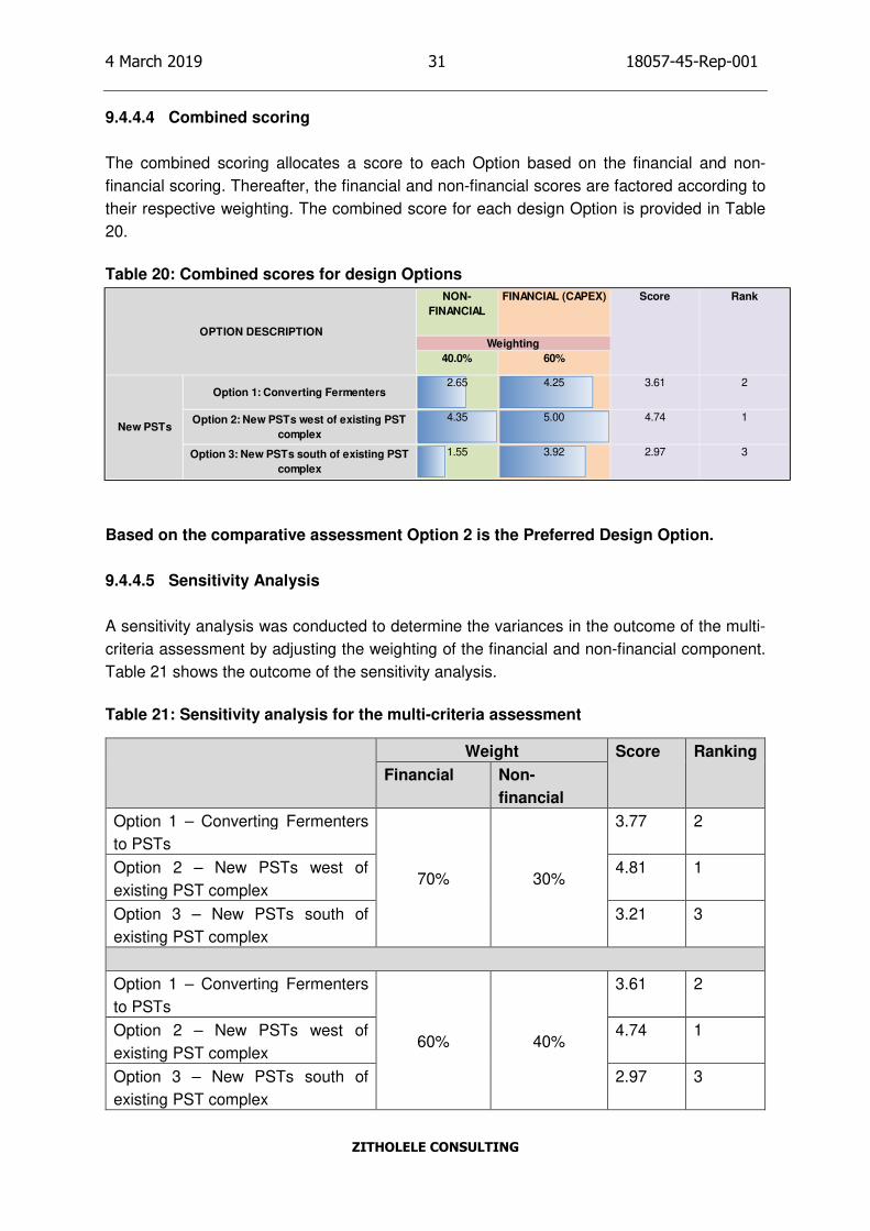
9.4.4.4 Combined scoring
The combined scoring allocates a score to each Option based on the financial and non-
financial scoring. Thereafter, the financial and non-financial scores are factored according to
their respective weighting. The combined score for each design Option is provided in Table
20.
Table 20: Combined scores for design Options
Based on the comparative assessment Option 2 is the Preferred Design Option.
9.4.4.5 Sensitivity Analysis
A sensitivity analysis was conducted to determine the variances in the outcome of the multi-
criteria assessment by adjusting the weighting of the financial and non-financial component.
Table 21 shows the outcome of the sensitivity analysis.
Table 21: Sensitivity analysis for the multi-criteria assessment
Weight Score Ranking
Financial Non-
financial
Option 1 – Converting Fermenters
to PSTs
70% 30%
3.77 2
Option 2 – New PSTs west of
existing PST complex
4.81 1
Option 3 – New PSTs south of
existing PST complex
3.21 3
Option 1 – Converting Fermenters
to PSTs
60% 40%
3.61 2
Option 2 – New PSTs west of
existing PST complex
4.74 1
Option 3 – New PSTs south of
existing PST complex
2.97 3
NON-
FINANCIAL
FINANCIAL (CAPEX)
40.0% 60%
Option 1: Converting Fermenters2.65 4.25 3.61 2
Option 2: New PSTs west of existing PST
complex
4.35 5.00 4.74 1
Option 3: New PSTs south of existing PST
complex
1.55 3.92 2.97 3
OPTION DESCRIPTION
New PSTs
Weighting
Score Rank
Page 42
4 March 2019 32 18057-45-Rep-001
ZITHOLELE CONSULTING
Weight Score Ranking
Financial Non-
financial
Option 1 – Converting Fermenters
to PSTs
50% 50%
3.45 2
Option 2 – New PSTs west of
existing PST complex
4.68 1
Option 3 – New PSTs south of
existing PST complex
2.74 3
Option 1 – Converting Fermenters
to PSTs
40% 60%
3.29 2
Option 2 – New PSTs west of
existing PST complex
4.61 1
Option 3 – New PSTs south of
existing PST complex
2.50 3
Option 1 – Converting Fermenters
to PSTs
30% 70%
3.13 2
Option 2 – New PSTs west of
existing PST complex
4.55 1
Option 3 – New PSTs south of
existing PST complex
2.26 3
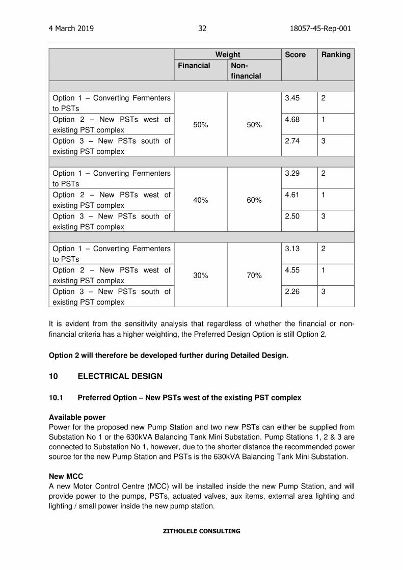
It is evident from the sensitivity analysis that regardless of whether the financial or non-
financial criteria has a higher weighting, the Preferred Design Option is still Option 2.
Option 2 will therefore be developed further during Detailed Design.
10 ELECTRICAL DESIGN
10.1 Preferred Option – New PSTs west of the existing PST complex
Available power
Power for the proposed new Pump Station and two new PSTs can either be supplied from
Substation No 1 or the 630kVA Balancing Tank Mini Substation. Pump Stations 1, 2 & 3 are
connected to Substation No 1, however, due to the shorter distance the recommended power
source for the new Pump Station and PSTs is the 630kVA Balancing Tank Mini Substation.
New MCC
A new Motor Control Centre (MCC) will be installed inside the new Pump Station, and will
provide power to the pumps, PSTs, actuated valves, aux items, external area lighting and
lighting / small power inside the new pump station.
Page 43
4 March 2019 33 18057-45-Rep-001
ZITHOLELE CONSULTING
The MCC shall be designed in accordance with SANS 60439 & 1973-1, and will be of a fixed
pattern, consisting of modular free standing sections, bolted together to form an extensible
MCC. Each section shall comprise of cubicles / starter drives.
11 CONTROL AND INSTRUMENTATION
11.1 Scope of Work.
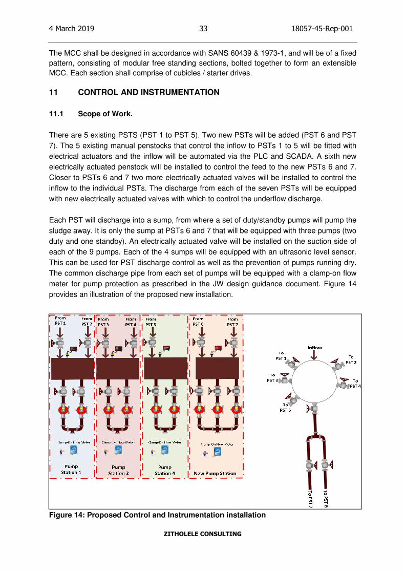
There are 5 existing PSTS (PST 1 to PST 5). Two new PSTs will be added (PST 6 and PST
7). The 5 existing manual penstocks that control the inflow to PSTs 1 to 5 will be fitted with
electrical actuators and the inflow will be automated via the PLC and SCADA. A sixth new
electrically actuated penstock will be installed to control the feed to the new PSTs 6 and 7.
Closer to PSTs 6 and 7 two more electrically actuated valves will be installed to control the
inflow to the individual PSTs. The discharge from each of the seven PSTs will be equipped
with new electrically actuated valves with which to control the underflow discharge.
Each PST will discharge into a sump, from where a set of duty/standby pumps will pump the
sludge away. It is only the sump at PSTs 6 and 7 that will be equipped with three pumps (two
duty and one standby). An electrically actuated valve will be installed on the suction side of
each of the 9 pumps. Each of the 4 sumps will be equipped with an ultrasonic level sensor.
This can be used for PST discharge control as well as the prevention of pumps running dry.
The common discharge pipe from each set of pumps will be equipped with a clamp-on flow
meter for pump protection as prescribed in the JW design guidance document. Figure 14
provides an illustration of the proposed new installation.
Figure 14: Proposed Control and Instrumentation installation
Page 44
4 March 2019 34 18057-45-Rep-001
ZITHOLELE CONSULTING
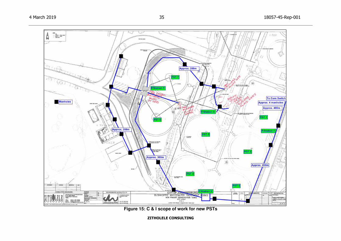
Currently the discharge from PSTs 1 and 2 goes to Pump Station 1, the discharge from PSTs
3 and 4 goes to Pump Station 2 and the discharge from PST 5 goes to Pump Station 4. The
equipment from these pump stations are wired to the PLC in the “Tower” at the old main admin
building. Because this PLC equipment has reached the end of its life (i.e. it is not being
manufactured anymore), a new PLC (Schneider M580) will be installed in Pump Station 5 (i.e.
the pump station for PSTs 6 and 7). Remote I/O racks, also with Schneider M580 PLC
equipment, will be installed in Pump Stations 1, 2 and 4. These will then all be remote I/O for
the main PLC panel in Pump Station 5. The hard-wired cabling from pump stations 1, 2 and 4
will therefore become obsolete and the unused PLC hardware will provide much-needed
spares for Bushkoppie works. One data communication fibre-optic cable will be installed from
this new PLC to the core switch in the “Tower” to link this new PLC and all its remote I/O to
the Bushkoppie data network. Due to the road alterations which will be done to accommodate
the new PSTs, the fibre-optic data cables to the Main Intake Sub and to the new main admin
building will be re-routed. These data cables, together with the data cable for the new PSTs
PLC will run beside the road from the “Tower”, around PSTs 3 and 4 to the new PLC, the main
admin and the main intake sub. Figure 15 shows the C & I scope of work for the new PSTs.
Page 45
4 March 2019 35 18057-45-Rep-001
ZITHOLELE CONSULTING
Figure 15: C & I scope of work for new PSTs
Page 46
4 March 2019 36 18057-45-Rep-001
ZITHOLELE CONSULTING
12 STRUCTURAL DESIGN
12.1 General Design Philosophy
The purpose of the design is the achievement of acceptable probabilities, as defined in the
relevant SANS Codes of Practice that the structures being designed will not become unfit for the
use for which it is intended. Two limit states of design are considered; the Ultimate Limit State,
and the Serviceability Limit State. The Ultimate Limit State (ULS) concerns safety, and considers
the maximum load-carrying capacity of the structure. The Serviceability Limit State (SLS) design
restricts excessive deformation or displacement, excessive local damage, excessive crack width,
excessive vibration and corrosion of reinforcement in concrete.
The recommended design approach, which has been followed, is to design on the basis of the
expected critical limit state and then to check that the remaining limit states will not be reached.
The analysis and design of the reinforced concrete, load bearing masonry and structural steel
components of the works were carried out using the PROKON suite of programs, version
W3.0.08, February 2016.
Blasting During Construction
Blasting will not be permitted during construction due to the risk of damage to existing structures.
Alternative methods of breaking up rock and hard material during excavations will be explored by
the Contractor.
Concrete Cover to Reinforcement
The minimum concrete cover to the reinforcement for each type of structure is specified in the
sections below. In accordance with BS 8007, a minimum cover of 50mm, suitable for severe and
very severe exposure conditions, was specified. In those instances where the concrete is
susceptible to chemical attack and the 50mm cover was deemed to be inadequate, coatings
providing the required degree of chemical resistance were specified in the Project Specifications
and on the drawings.
12.2 Liquid Retaining Structures
The term ‘liquid retaining structures’ includes structures designed to contain, or to exclude liquid,
and include the tanks and reactors and similar vessels on the one hand and valve chambers,
pump stations and the like on the other hand.
The critical limit state for the design of liquid retaining structures is the Serviceability Limit State,
which considers the development of cracks in immature (early drying shrinkage) and mature
concrete under service loads and temperature effects. The design entails element sizing and
determining the amount of reinforcement required to limit crack widths to within the specified
Page 47
4 March 2019 37 18057-45-Rep-001
ZITHOLELE CONSULTING
design limits. Once the reinforcement requirements have been established, compliance of the
structure with the ultimate limit state requirements is checked.
A geotechnical investigation will be conducted to confirm the founding conditions on site during
the detailed design stage.
Joints in Liquid Retaining Structures
The design of liquid retaining structures against early thermal movement and shrinkage is closely
related to the frequency and spacing of construction and expansion joints. All joint types and
positions are therefore indicated and specified on the relevant concrete layout drawings.
Codes of Practice
Serviceability Limit State:
• BS 8007: Code of practice for design of concrete structures for retaining aqueous
liquids.
Ultimate Limit State:
• SANS 10100-Part 1: The structural use of concrete - Design
• SANS 10100-Part 2: The structural use of concrete - Materials and workmanship
• SANS 2001-CC1:2007: Concrete works (Structural)
• SANS 10144: Detailing of steel reinforcement for concrete
• SABS 920: Steel bars for concrete reinforcement
• SANS 10160-Parts 1 to 8 (as applicable): Basis of structural design and actions
for buildings and industrial structures
Material Properties and Design Data
(i) Density of contained liquid: 11 kN/m3
(ii) Density of concrete: 24 kN/m3
(iii) Density of soil: 20 kN/m3
(iv) Internal friction angle of soil: 30 degrees
(v) Concrete classes:
Structural concrete: Class 35/19 (35 MPa)
Benching: Class 20/19 (20 MPa)
Blinding: Class 15/19 (15 MPa)
(vi) Design crack width: 0,20mm (severe or very severe exposure)
(vii) Concrete cover to reinforcement: 50mm (minimum)
General Loading, Analysis and Design of Liquid Retaining Structures
In accordance with the relevant design codes, the liquid level inside the structures is taken as the
top of the working top liquid level for the serviceability limit state design. For the ultimate limit state
design, liquid levels were taken to the tops of walls, assuming that all liquid outlets are blocked.
Page 48
4 March 2019 38 18057-45-Rep-001
ZITHOLELE CONSULTING
Allowance has been made for the effects of adverse soil pressure on walls due to compaction
and surcharge. The beneficial effect of external soil pressures on the liquid retaining structures in
the filled condition was ignored.
In non-cylindrical structures, an assessment was made of the pressures to be resisted by
horizontal and vertical bending moments in the walls. Allowance was also made for the effects of
direct tension in walls induced by flexural action in adjacent walls.
The maximum hoop tension in the walls of cylindrical structures was determined assuming a
pinned connection between the wall and the base. The maximum negative vertical bending
moments in the walls of cylindrical structures were determined by considering a fixed connection
at the wall/base interface. For the determination of positive midspan bending moments in the
walls, a pinned connection was assumed.
As a rule, the floor slabs in both cylindrical and non-cylindrical structures were not monolithic with
the wall foundations. The floors were divided into panels separated by sealed expansion joints,
and either fibre-reinforced, or reinforced with high tensile steel reinforcement, as specified on the
drawings.
The partial load factor for retained liquids and external soil pressure for the ultimate limit state
was taken as 1.35.
12.3 Earth Retaining Structures
The preferred design Option for the two new PSTs will entail construction of earth retaining
structures/retaining walls are required to accommodate the change in grade of the natural ground
level over the site of the proposed works, and to create the required elevations for the various
components of the works. Primarily, use is made of reinforced concrete retaining walls and, where
required or allowed by the topography of the site, concrete block retaining structures.
Design Philosophy
The lateral earth pressures behind the walls were determined by considering the internal angle of
friction of the retained soil (which will generally be specified to be a granular material), the
surcharge at the top of the fill behind the wall, as well as the direction and magnitude of movement
the retaining structure is expected to undergo. The latter is required to ensure that the correct soil
pressure coefficient is used. The at-rest pressure coefficient assumes no lateral movement of the
wall while the active pressure develops when lateral movement of the wall takes place. Friction
between the back of the concrete wall and the soil backfill was ignored, this is a conservative
approach. The friction coefficient between the underside of the base and the foundation material
was taken as 0,50.
Page 49
4 March 2019 39 18057-45-Rep-001
ZITHOLELE CONSULTING
The allowance for the build-up of water behind the retaining wall was eliminated by designing and
specifying suitable sub-soil drainage systems for the walls. This eliminates the hydrostatic
pressure and improves the stability of the material behind the wall.
The factor of safety of the wall against sliding and overturning was taken as 1,5 under service
loads. The partial load factors for dead loads (1,2), soil loads (1,4) and imposed loads (1,6) used
are in accordance with the requirements of SANS 10160. The factorised loads were used for the
Ultimate Limit State design of the wall, including wall thickness and reinforcement requirements.
Codes of Practice
• SANS 10100-Part 1: The structural use of concrete - Design
• SANS 10100-Part 2: The structural use of concrete - Materials and workmanship
• SANS 2001-CC1:2007: Concrete works (Structural)
• SANS 10144: Detailing of steel reinforcement for concrete
• SABS 920: Steel bars for concrete reinforcement
• SANS 10160-Parts 1 to 8 (as applicable): Basis of structural design and actions
for buildings and industrial structures
Material Properties and Design Data
(i) Density of contained liquid: 11 kN/m3
(ii) Density of concrete: 24 kN/m3
(iii) Density of soil: 20 kN/m3
(iv) Internal friction angle of soil: 30 degrees
(v) Concrete classes:
(vi) Structural concrete: Class 35/19 (35 MPa)
(vii) Benching: Class 20/19 (20 MPa)
(viii) Blinding: Class 15/19 (15 MPa)
(ix) Concrete cover to reinforcement: 50mm (minimum)
12.4 Buildings
Design Philosophy
Buildings that will be constructed as part of this project include new Pump Stations.
Codes of Practice
• SANS 10160-Parts 1 to 8 (as applicable): Basis of structural design and actions
for buildings and industrial structures
• SANS 10100-Part 1: The structural use of concrete - Design
• SANS 10100-Part 2: The structural use of concrete - Materials and workmanship
• SANS 2001-CC1:2007: Concrete works (Structural)
• SANS 10144: Detailing of steel reinforcement for concrete
• SABS 920: Steel bars for concrete reinforcement
Page 50
4 March 2019 40 18057-45-Rep-001
ZITHOLELE CONSULTING
• SANS 10162-Part 1: The structural use of steel –Design (Hot rolled steelwork)
• SANS 10164-Part 1: The structural use of masonry (Unreinforced)
Material Properties and Design Data
The following material properties are applicable to the buildings:
(i) Density of concrete: 24 kN/m3
(ii) Concrete classes:
(iii) Structural concrete: Class 35/19 (35 MPa)
(iv) Benching: Class 20/19 (20 MPa)
(v) Blinding: Class 15/19 (15 MPa)
(vi) Concrete cover to reinforcement: 30mm (minimum)
(vii) Reinforcement: High yield bars (fy=450 N/mm2) and Mild steel bars (fy=250
N/mm2)
(viii) All Steelwork to be Grade 355JR and hot-rolled steelwork will be used for the
steelwork on the project
(ix) Density of steel: 7850 kg/m3
(x) Load-bearing masonry to be from masonry clay brick units – NFX/NFP with
mortar class II
The following design data was considered in the designs for the buildings:
(i) All floor slabs (except for roofs) was taken as for offices (2.5kN/m2) and as
industrial (5kN/m2) for the pump station buildings.
(ii) The wind loading has been taken into account for the structures and a factor of
1.2 has been used for ULS designs and 1.3 (uplift) and 0.9 for SLS.
(iii) No seismic or accidental loads have been taken into account for the designs
and these will be done in the detailed designs.
13 ENVIRONMENTAL AUTHORISATION
The applicability of the activities listed in Government Notice No. R.327, promulgated in terms of
the National Environmental Management Act (107 of 1998) were determined based on the scope
of work and planned project activities.
Accordingly, a Basic Assessment (BA) Process in accordance with Regulations 16-20 of the
NEMA EIA Regulations 2014, as amended (Government Notice No. R.326) and a Water Use
License in terms Section 21 of the National Water Act (Act 36 of 1998) as amended, will be
required.
14 HEALTH AND SAFETY
A Health and Safety Practitioner must be consulted during the detailed design stage of the project
to advise on any health and safety requirements that need to be addressed prior to construction.
Page 51
4 March 2019 41 18057-45-Rep-001
ZITHOLELE CONSULTING
15 RISK MANAGEMENT
The two current major risks on this project are as follows:
• Project funding – the uncertainty of securing the full project budget for this long term
project may impact on whether this project will proceed as programmed, or not.
• Environmental authorisation – getting an environmental authorisation may delay the
implementation of the project.
16 PROJECT PROGRAMME
The project programme is updated monthly as part of the reporting to JW. The Project Programme
as updated in December 2018 can be found in Appendix A.
17 PROJECT INVESTMENT
A summary of the consolidated project investment is provided in Table 22.
Table 22: Consolidated summary of costs
Summary of Costs
Description Amount (R)
New PSTs Preferred Option R 48 297 625.00
Refurbishment of Existing Pump Stations R 5 628 500.00
Refurbishment Existing PSTs R 15 110 850.00
Refurbishment Existing Fermenters R 5 531 315.00
Sub-Total 1 R 74 568 290.00
Contingencies at 10% R 7 456 829.00
Sub-Total 2 (excl. VAT) R 82 025 119.00
VAT at 15% R 12 303 800.00
Total (Incl. VAT) R 94 328 919.00
Detailed cost estimates can be found in Appendix B.
18 WAY FORWARD
The Preliminary Design Report documents the options considered as part of the Preliminary
Design as well as the preferred design options that will be developed further during the Detailed
Design. The following design options will be developed further during the Detailed design:
1. New PSTs Option 2 – Positioning new PSTs west of the existing PST complex
2. Refurbishing Existing Pump Stations Option 2 – Pump Station with a wet well (pumps with a flooded suction)
Page 52
4 March 2019 42 18057-45-Rep-001
ZITHOLELE CONSULTING
3. Refurbishing existing PSTs
4. Refurbishing existing Fermenters
Approval of this report is required for Zitholele to commence with the next stage of the project,
viz. Detailed Design.
ZITHOLELE CONSULTING (PTY) LTD
Z:\PROJECTS\18057 - BK NEW PSTS #2\4 REPORTS\45 ENGINEERING\18057-45-REP-001-PRELIMINARY DESIGN REPORT\18057-45-REP-001-PRELIMINARY DESIGN
REPORT REV 2.DOCX
Page 53
ZITHOLELE CONSULTING
APPENDIX A : PROJECT PROGRAMME
Page 54
ZITHOLELE CONSULTING
APPENDIX B : DETAILED COST ESTIMATES