Page 1
GeoAust Geotechnical Engineers Pty LtdACN: 114 447 371 ABN: 14 030 388 760
1/63 Industrial Drive, Braeside Vic. 3195Tel: (03) 9587 1811 Fax: (03) 9587 9411E-mail: [email protected]
PRELIMINARY GEOTECHNICAL ASSESSMENT
WERRIBEE EMPLOYMENT PRECINCT
PRINCES HIGHWAY
WERRIBEE VIC
PREPARED FOR
VICURBAN
JOB NO: 1548-3-R
7 APRIL 2009
DISTRIBUTION:
VICURBAN
Page 2
Preliminary Geotechnical Assessment 1548-3-R
Werribee Employement Precinct, Princes Highway, WERRIBEE VIC 7/04/09
0
TABLE OF CONTENTS
1 INTRODUCTION 1
1.1 COMMISSION 11.2 PROPOSED DEVELOPMENT 11.3 AIM OF PRELIMINARY ASSESSMENT 11.4 GEOLOGY 1
2 INVESTIGATION METHODS 2
2.1 FIELD METHODS 22.1.1 Boreholes 22.1.2 In-situ Testing 3
2.2 LABORATORY TESTING 3
3 RESULTS OF INVESTIGATION 4
3.1 GENERAL SITE DESCRIPTION 43.2 SITE DESCRIPTION AT BOREHOLE LOCATIONS 63.3 BOREHOLE LOCATIONS 113.4 SUBSURFACE CONDITIONS 113.5 GROUND WATER 123.6 LABORATORY TESTS 13
4 COMMENTS AND RECOMMENDATIONS 13
4.1 PRELIMINARY REPORT 144.2 SITE CLASSIFICATION 144.3 EARTHQUAKE SITE CLASSIFICATION 144.4 EXISTING DPI BUILDINGS – PROBABLE CAUSES OF FOOTING SUBSIDENCE 154.5 NEW STRUCTURES SOUTH WEST OF LINE A-A 17
4.5.1 Residential Structures 174.5.2 Low Rise Commercial Structures 174.5.3 Multi Level Commercial Structures 18
4.6 NEW STRUCTURES NORTH EAST OF LINE A-A 184.6.1 Residential Structures 184.6.2 Low Rise Commercial Structures 194.6.3 Multi Level Commercial Structures 19
4.7 STRUCTURES CONSTRUCTED OVER BACKFILLED DAMS AND DRAINS 204.8 EXCAVATION 20
4.8.1 Excavation Conditions 204.8.2 Site Trafficability During Construction 21
4.9 RETENTION OF SITE EXCAVATIONS 214.9.1 Retention Systems 214.9.2 Lateral Earth Pressures 22
4.10 PAVEMENTS 234.10.1 Design and Construction of Pavements. 234.10.2 Subgrade Drainage and Moisture Control 24
4.11 EARTHWORKS 244.12 LIMITATIONS 25
Page 3
Preliminary Geotechnical Assessment 1548-3-R
Werribee Employement Precinct, Princes Highway, WERRIBEE VIC 7/04/09
1
1 INTRODUCTION
1.1 COMMISSION
The preliminary geotechnical assessment was commissioned by Mr Tom Maidment of VicUrban.
The scope of works was in accordance with our fee proposal with reference 1548-1-Q, dated 31
December 2008.
1.2 PROPOSED DEVELOPMENT
It is understood that the details of the proposed development have not been formalised, however
conceptually the proposed redevelopment of the 925 hectare, Werribee Agriculture and Food
Technology Precinct site is likely to incorporate structures ranging from low density residential
dwellings through to multilevel commercial developments. It is anticipated that the larger
commercial developments may include one or more basement levels.
1.3 AIM OF PRELIMINARY ASSESSMENT
The aim of the geotechnical assessment was to provide preliminary information on excavation,
retention, earthworks and the design and construction of foundations and pavements for the
anticipated range of structures.
1.4 GEOLOGY
The subject site is situated partly on the Werribee River delta deposits and partly on the Newer
Volcanics of the Werribee Plains. These areas form part of the catchment known as the Werribee
River Basin.
Reference to the Geological Survey of Victoria, 1:63,360 series, Melbourne sheet indicates the site
to be underlain by Aeolian deposits of the Quaternary age, which comprise a thin veneer of
windblown silt and clayey silt (loess). The Geological Survey of Victoria indicates the Aeolian
deposits to be underlain by olivine basalt, locally referred to as ‘Newer Volcanics’. The basalt is of
Quaternary age and the residual clays associated with weathering of the basalt are typically highly
reactive. The depth to basalt is often highly variable over short lateral distances and the mechanical
properties of the basalt are also often highly variable over short distances, both laterally and
vertically.
Page 4
Preliminary Geotechnical Assessment 1548-3-R
Werribee Employement Precinct, Princes Highway, WERRIBEE VIC 7/04/09
2
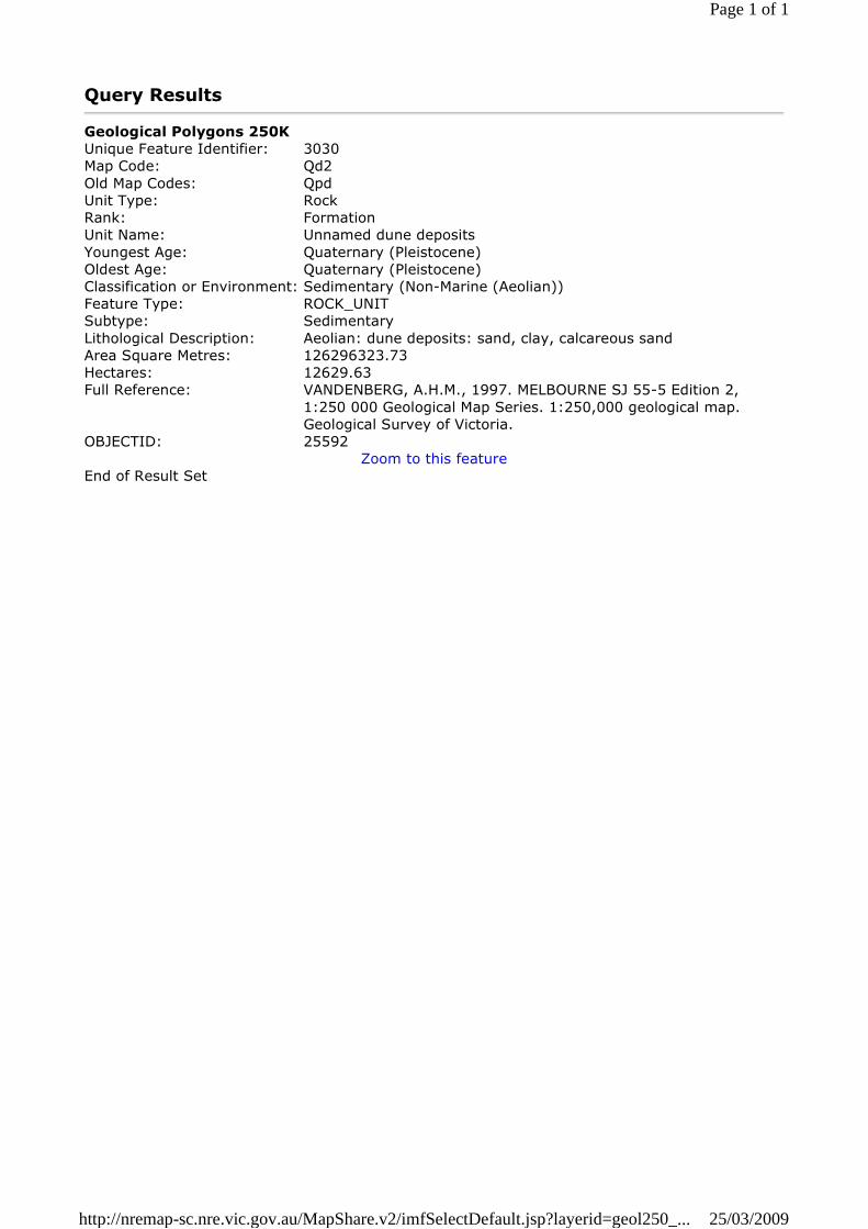
The GeoVic website by the Department of Primary Industry (DPI) (http://www.dpi.vic.gov.au)
indicates geological conditions varying slightly from those indicated on the Geological Survey of
Victoria, 1:63,360 series, Melbourne sheet. The GeoVic website indicates a large portion of the site
to be underlain by Quaternary age Aeolian deposits comprising sand, clay, calcareous sand. The
north east portion of the site is underlain by Quaternary age olivine basalt, locally referred to as
‘Newer Volcanics’. A map of the site geology derived from the GeoVic website, including a
description of the various geologies at and adjacent to the site is given in Appendix A.
Drillers logs of various ground water bores at the site, sourced from the GeoVic website, indicated
the basalt rock to extend to depths in excess of 45 metres below the existing ground surface. The
basalt appears to consist of two separate flows of lava, which are separated by a 5 – 6 metre thick
layer of extremely weathered basalt at and approximately depth of 30 metres below the existing
ground surface. A map of the borehole locations derived from the GeoVic website, and the drillers
logs are given in Appendix B.
The basalt flows extend to depths significantly in excess of those likely to be influenced by any
proposed structures at the site.
2 INVESTIGATION METHODS
2.1 FIELD METHODS
Field work was completed on 11 and 12 March 2009 under the direct supervision of a geotechnical
engineer from GeoAust and included the following.
2.1.1 Boreholes
Eighteen boreholes were drilled to depths ranging between 0.9 and 6.4 metres below the existing
ground surface at the approximate locations indicated in Figure 1. Boreholes were drilled using a
truck mounted rotary drilling rig equipped with 100mm diameter continuous flight augers. All
boreholes were drilled to effective auger refusal on medium to high strength basalt.
Bore logs were prepared in accordance with AS 1726-1993 ‘Geotechnical Site Investigations’.
Definitions of the logging terms and symbols used are provided in Appendix C and the logs of the
boreholes are provided in Appendix D.
Page 5
Preliminary Geotechnical Assessment 1548-3-R
Werribee Employement Precinct, Princes Highway, WERRIBEE VIC 7/04/09
3
2.1.2 In-situ Testing
Testing was carried out in accordance with the relevant test procedures given in Australian Standard
AS1289 ‘Methods of Testing Soil for Engineering Purposes’ and included the following:
Vane shear strength testing of cohesive soils.
Standard Penetration Testing (SPT).
Test results are included on the logs of the bores.
2.2 LABORATORY TESTING
Testing was undertaken by the laboratory of Bairnsdale Soil and Concrete Testing Pty Ltd. The
laboratory is accredited by the National Association of Testing Authorities (NATA).
Testing was carried out in accordance with Australian Standard 1289, ‘Methods of Testing Soil for
Engineering Purposes’ and included:
5 No. Atterberg Limit tests.
2 No 4 day soaked California Bearing Ratio (CBR) tests.
The Atterberg Limit tests were performed on the following disturbed sample of silty clay:
Borehole 3, 0.5 – 0.6 metre.
Borehole 4, 0.7 – 0.8 metre.
Borehole 5, 0.5 – 0.6 metre.
Borehole 5, 0.9 – 1.0 metre.
Borehole 7, 3.0 – 3.45 metre.
The soaked CBR tests were performed on composite samples of silt (Composite Sample A) and silty
clay (Composite Sample B). The composite sample was formed using the following samples of
disturbed silt and clay:
Composite Sample A – (Aeolian Silt)
Borehole 1, 0.2 – 1.0m
Borehole 2, 0.3 – 1.0m
Borehole 4, 0.2 – 0.7m
Borehole 5, 0.2 – 0.7m
Borehole 9, 0.2 – 0.5m
Page 6
Preliminary Geotechnical Assessment 1548-3-R
Werribee Employement Precinct, Princes Highway, WERRIBEE VIC 7/04/09
4
Composite Sample B – (Residual Basaltic Clay)
Borehole 3, 0.3 – 0.7m
Borehole 6, 0.2 – 1.0m
Borehole 11, 0.2 – 1.0m
Borehole 12, 0.2 – 1.0m
Borehole 13, 0.2 – 1.0m
Borehole 14, 0.2 – 0.9m
Borehole 15, 0.2 – 1.0m
Borehole 16, 0.2 – 1.0m
Borehole 17, 0.2 – 1.0m
Borehole 18, 0.2 – 1.0m
The CBR specimens were remoulded to 98% of the Standard maximum dry density ratio in
accordance with Australian Standard AS1289 5.1.1.
The results of the laboratory tests are presented in Appendix E.
3 RESULTS OF INVESTIGATION
3.1 GENERAL SITE DESCRIPTION
The following site features were noted at the time of the site testing:
The site was located within essentially flat topography. Consequently, the surface drainage of
the site was generally very poor. The poor drainage characteristics of the site were previously
extensively utilised at the site to flood irrigate large sections of the site. Based on information
provided by Department of Primary Industries (DPI) up to 700 mega litres of water from the
Werribee River was used to flood irrigate the property. The practice was continued up until
the 1999, with much of the site being flood irrigated on a daily basis. The only area of the site
which is currently still being irrigated is the Vegetable Growers Association market gardens
located to the south of 639 Sneydes Road. Up to 5 mega litres of water per annum is being
used to irrigate the market gardens. The source of the water was unknown.
The majority of the existing one and two level DPI structures have performed extremely
poorly. A number of the structures have been at least partially vacated because of the
extensive cracking and distortion, and several buildings have been entirely vacated.
Page 7
Preliminary Geotechnical Assessment 1548-3-R
Werribee Employement Precinct, Princes Highway, WERRIBEE VIC 7/04/09
5
It is understood that the operational structures date back to 1939, although many of the poorly
performing structures are less than 15 years of age and were built to current building
standards. Typically, the structures were constructed on either conventional pad and strip
footings, or stiffened raft slabs. The footings and slabs have settled and rotated variably. At
least one of the buildings was underpinned to a depth of 2.0 metres below the existing ground
surface, without benefit. A section of the same structure was subsequently underpinned to a
depth of 3.0 - 4.0 metres and has apparently performed satisfactorily since.
At the north east end of the site there were a number of low rise structures fronting onto
Princes Highway and the north end of Hoppers Road. The structures included those at the
sites operated by Melbourne University, Mercy Werribee Hospital and Victoria University.
GeoAust was unable to carry out detailed inspections of the structures at these sites as part of
the work completed. However, anecdotal information provided to us and a cursory external
inspection of the structures from areas able to be accessed by the public did not indicate the
presence of significant cracking and/or distortion of structures resulting from foundation
movements.
Vegetation at the site comprised predominantly grass, but also included wheat and a
significant number of medium to very large sized trees. A considerable number of trees
appeared to be of poor to very poor health. There were numerous trees scattered around the
various DPI buildings, many of them within relatively close proximity to the structures.
Appreciable earthworks have been carried out at the site. These include:
Construction of the Melbourne Water stormwater drains through the site. The locations
of the drains are indicated on the Services Location Plan prepared by Arup.
Construction of a significant number of water channels as part of the flood irrigation
scheme. The channels were most evident towards the west end of the site.
Re-levelling of substantial areas of the site including construction of low height levies
(typically less than 0.2 metres in height) to facilitate the flood irrigation at the site.
Excavation of numerous farm dams. It is understood that some of the older dams were
backfilled, possibly with rubbish and animal carcasses.
Excavation and subsequent backfilling of a number of rubbish pits and livestock burial
pits. The approximate locations of the rubbish pits and burial pits are given in the report
prepared by Compass Environmental Pty Ltd. Based on information provided by Ms Lyn
McCluskey of DPI one or more of the burial pits contain radioactive carcasses.
Page 8
Preliminary Geotechnical Assessment 1548-3-R
Werribee Employement Precinct, Princes Highway, WERRIBEE VIC 7/04/09
6
Construction of the bridge abutments for the Sneydes Road Bridge over the Maltby
Bypass.
Construction of the Melbourne Water Western Trunk Sewer through the site. At the
north east corner of the site the trunk sewer comprises a tunnel with an invert level of
approximately 25 metres below the ground surface. To the south east of the Melbourne
Water Hoppers Crossing Pumping Station the sewer was constructed using cut and cover
construction techniques. The sewer replaced the original brick lined, open channel sewer
located along the north side of the Maltby Bypass.
Minor cut and fill earthworks to accommodate the various existing buildings at subject
site.
3.2 SITE DESCRIPTION AT BOREHOLE LOCATIONS
The following site features were noted at the time of the site testing in the vicinity of the borehole
locations:
Borehole 1
Land Use: Pasture.
Vegetation: Grass.
Numerous small to large trees along the north fence line.
Drainage: Poor.
Irrigation: Perimeter water channels with weirs and low height earth levies at regular
centres indicated the area was previously flood irrigated.
Borehole 2
Land Use: Pasture.
Vegetation: Grass.
A row of very large trees (mostly dead) along the east fence line.
Small to large trees along the road reservation to the south of the site.
Drainage: Poor
Irrigation: Perimeter water channels with weirs and low height earth levies at regular
centres indicated the area was previously flood irrigated.
Heavily irrigated market gardens immediately to the east of the paddock.
Page 9
Preliminary Geotechnical Assessment 1548-3-R
Werribee Employement Precinct, Princes Highway, WERRIBEE VIC 7/04/09
7
Borehole 3
Land Use: Pasture.
Vegetation: Grass.
Numerous medium to large trees scattered.
Drainage: Poor.
A Melbourne Water stormwater drain was located a short distance to the east of
the bore location. The drain was estimated to be approximately 3 metres deep
and there was an approximate 0.5 – 1.0 metre depth of stagnant water within
the drain.
Irrigation: No evidence of previous flood irrigation.
Borehole 4
Land Use: Landscaped area in front of DPI offices at 600 Sneydes Road.
Vegetation: Grass.
Numerous medium to large trees scattered.
Drainage: Poor.
The landscaped area to the south of the DPI offices was graded such that all
surface runoff water would flow into a central pond. The pond was dry.
Irrigation: Perimeter water channels with weirs indicated that the area was flood irrigated
prior to the construction of the DPI offices.
Borehole 5
Land Use: Pasture.
Vegetation: Grass.
A row of medium to very large trees along the south property boundary. The
trees appeared to be in very poor health. Many of the trees appeared dead.
Drainage: Poor.
Irrigation: Perimeter water channels with weirs and low height earth levies at regular
centres indicated the area was previously flood irrigated.
Borehole 6
Land Use: Pasture.
Vegetation: Grass
There was a stand of medium to large trees to the south of the borehole and a
row of medium to large trees along the north fence line.
Drainage: Poor
Irrigation: No evidence of previous flood irrigation.
Page 10
Preliminary Geotechnical Assessment 1548-3-R
Werribee Employement Precinct, Princes Highway, WERRIBEE VIC 7/04/09
8
Borehole 7
Land Use: Pasture.
Vegetation: Grass.
There was a row of medium to large trees between the north fence line and
Sneydes Road.
Drainage: Poor.
Melbourne Water stormwater drains were located to the east and west of the
bore location. The drain to the east was estimated to be approximately 1.5
metres deep and he base of the drain was concrete lined.
In addition to the Melbourne Water drains the paddock was intersected by a
shallow unlined drain, which was approximately 0.4 – 0.5 metres deep. The
spoil from the excavation of the drain was spread over the paddock in the area
of Borehole 7.
Irrigation: No evidence of previous flood irrigation.
Borehole 8
Land Use: Wheat field.
Vegetation: Wheat stubble.
Drainage: Poor.
Irrigation: No evidence of previous flood irrigation.
Borehole 9
Land Use: Pasture.
Vegetation: Grass.
A row of medium to large trees along the west fence line.
Drainage: Poor.
Irrigation: Perimeter water channels with weirs and low height earth levies at regular
centres indicated the paddock was previously flood irrigated.
Borehole 10
Land Use: Pasture.
Vegetation: Grass.
A row of medium to large trees along the west fence line.
Drainage: Poor.
Irrigation: No evidence of previous flood irrigation.
Page 11
Preliminary Geotechnical Assessment 1548-3-R
Werribee Employement Precinct, Princes Highway, WERRIBEE VIC 7/04/09
9
Borehole 11
Land Use: Wheat field.
Vegetation: Wheat stubble.
Drainage: Poor.
There was an unlined drainage channel to the south of the borehole. The
channel, which was approximately 1 metre deep, was dry
Irrigation: No evidence of previous flood irrigation.
Other: There was a large stockpile of predominantly clay fill immediately to the north
of the paddock. The stockpile of fill was located along the south property
boundary of the adjacent Victoria University site.
Borehole 12
Land Use: Wheat field.
Vegetation: Wheat stubble.
There was a stand of large trees to the south west of the borehole.
Drainage: Poor.
Irrigation: No evidence of previous flood irrigation.
Borehole 13
Land Use: Wheat field.
Vegetation: Wheat stubble.
There was a stand of large trees to the east of the borehole and a row of medium
trees along the west fence line.
Drainage: Poor.
Irrigation: No evidence of previous flood irrigation.
Borehole 14
Land Use: Wheat field.
Vegetation: Wheat stubble.
Drainage: Poor.
Irrigation: No evidence of previous flood irrigation.
Page 12
Preliminary Geotechnical Assessment 1548-3-R
Werribee Employement Precinct, Princes Highway, WERRIBEE VIC 7/04/09
10
Borehole 15
Land Use: Wheat field.
Vegetation: Wheat stubble.
There was a row of large trees to the east of the borehole along Hackett Road.
Drainage: Poor.
Irrigation: No evidence of previous flood irrigation.
Other: There was small farm dam in the south east corner of the paddock. The dam
was estimated to be approximately 2 metres deep. The depth of water was
estimated to be less than 1 metre.
Borehole 16
Land Use: Wheat field.
Vegetation: Wheat stubble.
Drainage: Poor.
Irrigation: No evidence of previous flood irrigation.
Other: There was small farm dam in the north east corner of the paddock. The dam
was estimated to be approximately 2 metres deep. The depth of water was
estimated to be less than 1 metre.
Borehole 17
Land Use: Pasture.
Vegetation: Grass.
A row of medium to large trees along the north fence line.
Drainage: Poor.
Irrigation: No evidence of previous flood irrigation.
Other: There was excavation at the north end of the paddock towards the west end of
the row of trees. The purpose of the excavation, which was partially filled with
water was not immediately apparent. The near vertical sides of the excavation
indicated that the excavation may be a burial pit.
Borehole 18
Land Use: Pasture.
Vegetation: Grass.
Drainage: Poor.
Irrigation: No evidence of previous flood irrigation.
Page 13
Preliminary Geotechnical Assessment 1548-3-R
Werribee Employement Precinct, Princes Highway, WERRIBEE VIC 7/04/09
11
3.3 BOREHOLE LOCATIONS
Boreholes were drilled at the approximate locations indicated in Figure 1. The boreholes were
located on site using a hand held global positioning system unit, with an accuracy of ±5m.
Coordinates of the boreholes are given in Table 3.3.1 below.
Table 3.3.1: Borehole Location Data
Borehole MGA COORDINATES
1 55H 0295899, UTH 5803221
2 55H 0295946, UTH 5802645
3 55H 0296727, UTH 5803705
4 55H 0296687, UTH 5803049
5 55H 0296545, UTH 5802330
6 55H 0297516, UTH 5803703
7 55H 0297377, UTH 5802796
8 55H 0297318, UTH 5801759
9 55H 0298006, UTH 5801432
10 55H 0298014, UTH 5802274
11 55H 0298204, UTH 5803212
12 55H 0297823, UTH 5804474
13 55H 0298350, UTH 5804311
14 55H 0299371, UTH 5804758
15 55H 0299227, UTH 5803977
16 55H 0299176, UTH 5803146
17 55H 0299074, UTH 5802295
18 55H 0298540, UTH 5801755
3.4 SUBSURFACE CONDITIONS
The boreholes indicated the presence of variable subsurface soil conditions across the site.
To the north east of Line A-A indicated in Figure 1, Boreholes 3, 6 and 11 – 18 indicated the
presence of a soil and rock profile consistent with the weathering of the Quaternary age Newer
Volcanics. Typically, the residual soil profile comprised a 0.1 – 0.2 metre thick layer of high
plasticity clayey silt underlain by clay. The clay was silty, of high plasticity and of very stiff
consistency. At depths ranging between 0.7 and 3.4 metres below the existing ground surface
extremely weathered basalt was intercepted in each of the boreholes. The basalt was of extremely
low to very low rock strength, often containing an appreciable portion of high plasticity clay.
Page 14
Preliminary Geotechnical Assessment 1548-3-R
Werribee Employement Precinct, Princes Highway, WERRIBEE VIC 7/04/09
12
In each of the boreholes effective auger refusal was encountered on high strength basalt at depths
ranging between 0.9 and 3.9 metres below the existing ground surface. The refusal depths most
likely correspond to weathered basalt but possibly may correspond to a closeknit basalt boulder
layer, which may be underlain by additional depths of residual clay. This however can only be
verified by additional site investigation comprising NMLC diamond core drilling into the basalt.
To the south west of Line A-A indicated in Figure 1, Boreholes 1, 2, 4, 5 and 7 – 10 indicated the
presence of variable depths of Aeolian silts and clays underlain a soil and rock profile consistent
with the weathering of the Quaternary age Newer Volcanics. The depth of surficial silt ranged in
depth between a minimum of 0.2 metres and a maximum of 2.6 metres. The silt was typically of
moderate plasticity and medium density. Immediately underlying the silt high plasticity clay was
intercepted. The clay was typically of very stiff consistency. At shallow depths the clay was
associated with the Werribee Delta deposits. At highly variable depths the clay was consistent with
residual basaltic clay encountered to the north east of Line A-A. The clay was silty, of high plasticity
and of very stiff consistency. In each of the boreholes effective auger refusal was encountered on
basalt at depths ranging between 1.7 and 6.4 metres below the existing ground surface. The refusal
depths most likely correspond to high strength weathered basalt but possibly may correspond to a
closeknit basalt boulder layer, which may be underlain by additional depths of residual clay. This
however can only be verified by additional site investigation comprising NMLC diamond core
drilling into the basalt.
It should be noted that basalt boulders can occur within the residual basaltic clay. The boulders can
be quite large and their occurrence can be random. Furthermore, the depth to basalt can also vary
significantly over short lateral distances. The boreholes are unlikely to have identified either the
minimum or maximum depths to rock at the subject site.
3.5 GROUND WATER
The regional ground water table was not intercepted in any of the boreholes. No perched ground
water seepage was encountered in the silt overlying the clay during auguring of the boreholes or a
short time after their completion. No long term monitoring of ground water was undertaken. The
surficial silts are highly likely to become unworkable at shallow depth when saturated.
Based on experience of conditions in the general area the regional ground water table is likely to be
present at depths in excess of approximately 15 metres below the existing ground surface. The
lithology of the ground water aquifer comprises fractured basalt. The ground water in the general
area is typically quite saline, often rendering it unsuitable for even for irrigation.
Page 15
Preliminary Geotechnical Assessment 1548-3-R
Werribee Employement Precinct, Princes Highway, WERRIBEE VIC 7/04/09
13
3.6 LABORATORY TESTS
The laboratory test results are given in Appendix E of this report. The results of the Atterberg Limit
tests are summarised in Table 3.6.1 below:
Table 3.6.1: Summary of Atterberg Limit Test Results
Borehole
Sample
Depth
(metre)
Liquid Limit
(%)
Plastic Limit
(%)
Plasticity
Index (%)
Linear
Shrinkage
(%)
3 0.5 – 0.683 21 62 22
4 0.7 – 0.862 15 47 19
5 0.5 – 0.639 15 24 13
5 0.9 – 1.078 20 58 20.5
7 3.0 – 3.4599 18 81 25.5
The results of the Atterberg limit testing for the clay samples recovered from Boreholes 3, 4, 5 (0.9
– 1.0m) and 7 plot in the region of inorganic clay of high plasticity on the Unified Soil Classification
System Plasticity Chart. The results of the Atterberg limit testing for the silt sample recovered from
Borehole 5 (0.5 – 0.6m) plot in the region of inorganic medium plasticity on the Unified Soil
Classification System Plasticity Chart.
The results of the soaked CBR tests are summarised in Table 3.6.2 below:
Table 3.6.2: Summary of Soaked CBR Test Results
Sample ID Sample Type 4 Day Soaked CBR Value
Composite Sample A Aeolian Silt2.5
Composite Sample B Residual Basaltic Clay2.5
The results of the soaked CBR tests indicate low bearing strength. Based on the results of the tests
subgrade improvement is likely to be required for successful pavement performance.
Page 16
Preliminary Geotechnical Assessment 1548-3-R
Werribee Employement Precinct, Princes Highway, WERRIBEE VIC 7/04/09
14
4 COMMENTS AND RECOMMENDATIONS
4.1 PRELIMINARY REPORT
The scope of the investigation was formed on the basis of only conceptual detail of the proposed
development. The comments and recommendations of this report should be viewed as general and
preliminary in nature. Additional geotechnical investigation will e required for each element of the
proposed development once the details are finalised. The comments and recommendations of this
report must not be used for final structural design and construction.
The following comments and recommendations have been based on an extremely limited amount of
field and laboratory testing, which does not provide adequate coverage of the site for the proposed
development.
4.2 SITE CLASSIFICATION
Classification of the site has taken into account the following:
Identification of the sub soil profile.
Field classification of soil type and plasticity.
Established data on the performance of existing buildings on the soil profile.
Depth of fill.
Based on the poor performance of the existing DPI buildings to the south west of Line A-A
indicated in Figure 1, the site should be classified as ‘Class P’ in accordance with Australian
Standard AS2870 – 1996, ’Residential Slabs and Footings – Construction’.
4.3 EARTHQUAKE SITE CLASSIFICATION
Australian Standard AS 1170.4 – 2007, ‘Minimum Design Loads on Structures, Part 4: ‘Site Sub-
Soil Class’ outlines the methods for assigning the sites Sub-soil Class. Based on the anticipated
stratigraphy, Table 4.1 “Maximum Depth Limits for Sub-soil Class C” and Table 3.2 “Hazard Factor
(Z) For Specific Australian Locations” of the standard, we recommend the following Hazard Factor
and Sub-Soil Class are adopted:
Sub-soil Class: Class Ce – Shallow soil site
Hazard Factor (Z): 0.10
Page 17
Preliminary Geotechnical Assessment 1548-3-R
Werribee Employement Precinct, Princes Highway, WERRIBEE VIC 7/04/09
15
4.4 EXISTING DPI BUILDINGS – PROBABLE CAUSES OF FOOTING SUBSIDENCE
The site is underlain by high plasticity clay soils which undergo appreciable volumetric changes
when subjected to changes in moisture content. Upon wetting the clays swell appreciably and
conversely upon drying the clays shrink. The site is located within Climatic Zone 3, where seasonal
variation of temperature, humidity and rainfall influence the moisture condition of the soil profile to
a depth of at least 2.3 metres. External influences will influence the moisture content regime to
greater depths.
Under normal conditions where there are no appreciable external wetting or drying influences an
adequately designed and constructed footing arrangement should be capable of performing
satisfactorily, even on a high plasticity clay founding stratum. However once appreciable external
wetting and/or drying influences are introduced, the resultant heave and shrinkage related
movements are likely to significantly exceed those able to be accommodated by a structure
supported on conventional shallow spread footings.
The contributing factors to the poor performance of the existing DPI buildings are likely to include,
but not limited to the following:
Long Term Deep Seated Moisture Ingress
Much of the land on which the DPI buildings are situated was previously subjected to flood
irrigation. We understand that 700 megalitres of water per annum was used to irrigate
predominantly the west end of the site. The irrigation, which took place between approximately
1912 and 1999, would have caused significant deep seated moisture ingress into the underlying high
plasticity clays. Upon wetting the clays are likely to have heaved appreciably. Subsequent to the
cessation of flood irrigation the moisture content regime within the clay has been returning to its
long term equilibrium moisture content, resulting in ongoing shrinkage of the clay.
Poor Surface Drainage
Large areas of the site are essentially flat. Consequently, surface drainage of the site is very poor.
Seasonal moisture ingress during winter and spring when evaporation rates are low, followed by
prolonged dry periods during summer and autumn, when evaporation rates are high, lead to extreme
cyclical heave and shrinkage related movements of footings. Typically, structures rarely recover in
heave related movements the damage that is caused by the previous cycle of shrinkage related
movements. Consequently, the damage to the structures increases with each additional drying cycle.
Evidence of this can clearly be seen in the DPI Core Storage Facility where poor drainage has
caused appreciable distortion within the end walls of the portal frame structure.
Page 18
Preliminary Geotechnical Assessment 1548-3-R
Werribee Employement Precinct, Princes Highway, WERRIBEE VIC 7/04/09
16
Trees
The drying effects of trees are a common cause of foundation movement throughout Melbourne,
particularly within high plasticity clays such as those which are common to the west and north of
Melbourne. Individual trees located within 1.0 times their mature height of footings are recognised
as being capable of causing settlement related damage to structures in high plasticity clay. Groups
of trees are capable of causing damage over a considerably larger radius. The numerous trees
located within close proximity to the various DPI buildings are likely to have significantly
contributed to the settlement related damage observed within the structures.
Inadequate Footings
An investigation of the footings which provide support to the existing structure was not been carried
out as part of the investigation completed to date. However, based on the age and type of
construction of many of the buildings, and information provided by Mr Gary Nugent of DPI, a
considerable number of the existing DPI structures were constructed on shallow strip and pad
footings. Strip footings tend to perform poorly on high plasticity clay foundations. Typically, they
offer little protection against heave and shrinkage related movements. The corners of buildings
constructed on strip footings are most prone to settlements, resulting in racking cracks several
metres back from the corners of the walls. Additionally, strip footings are prone to rotation as a
result of the moisture gradient within the clay between the inside and outside of the footings. This
tends to cause outward rotation of walls.
Individually, any of the above factors are capable of causing appreciable foundation movements and
associated structural distress to a building constructed on high plasticity clay. However, if two or
more factors are combined the resultant damage to buildings can be significant, as has been observed
within the existing DPI buildings.
Page 19
Preliminary Geotechnical Assessment 1548-3-R
Werribee Employement Precinct, Princes Highway, WERRIBEE VIC 7/04/09
17
4.5 NEW STRUCTURES SOUTH WEST OF LINE A-A
4.5.1 Residential Structures
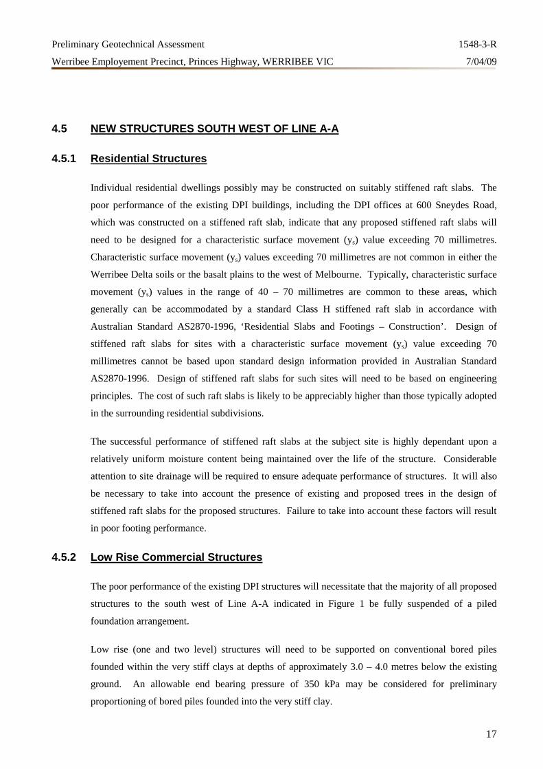
Individual residential dwellings possibly may be constructed on suitably stiffened raft slabs. The
poor performance of the existing DPI buildings, including the DPI offices at 600 Sneydes Road,
which was constructed on a stiffened raft slab, indicate that any proposed stiffened raft slabs will
need to be designed for a characteristic surface movement (ys) value exceeding 70 millimetres.
Characteristic surface movement (ys) values exceeding 70 millimetres are not common in either the
Werribee Delta soils or the basalt plains to the west of Melbourne. Typically, characteristic surface
movement (ys) values in the range of 40 – 70 millimetres are common to these areas, which
generally can be accommodated by a standard Class H stiffened raft slab in accordance with
Australian Standard AS2870-1996, ‘Residential Slabs and Footings – Construction’. Design of
stiffened raft slabs for sites with a characteristic surface movement (ys) value exceeding 70
millimetres cannot be based upon standard design information provided in Australian Standard
AS2870-1996. Design of stiffened raft slabs for such sites will need to be based on engineering
principles. The cost of such raft slabs is likely to be appreciably higher than those typically adopted
in the surrounding residential subdivisions.
The successful performance of stiffened raft slabs at the subject site is highly dependant upon a
relatively uniform moisture content being maintained over the life of the structure. Considerable
attention to site drainage will be required to ensure adequate performance of structures. It will also
be necessary to take into account the presence of existing and proposed trees in the design of
stiffened raft slabs for the proposed structures. Failure to take into account these factors will result
in poor footing performance.
4.5.2 Low Rise Commercial Structures
The poor performance of the existing DPI structures will necessitate that the majority of all proposed
structures to the south west of Line A-A indicated in Figure 1 be fully suspended of a piled
foundation arrangement.
Low rise (one and two level) structures will need to be supported on conventional bored piles
founded within the very stiff clays at depths of approximately 3.0 – 4.0 metres below the existing
ground. An allowable end bearing pressure of 350 kPa may be considered for preliminary
proportioning of bored piles founded into the very stiff clay.
Page 20
Preliminary Geotechnical Assessment 1548-3-R
Werribee Employement Precinct, Princes Highway, WERRIBEE VIC 7/04/09
18
Considerable attention to site drainage will be required to ensure adequate performance of structures.
It will also be necessary to take into account the presence of existing and proposed trees in the
design of footings for the proposed structures. Failure to take into account these factors will result in
poor footing performance.
4.5.3 Multi Level Commercial Structures
Multi-level structures will need to be suspended on piles which extend a short distance into high
strength basalt underlying the clay. An allowable end bearing pressure of 1000 - 3000 kPa may be
considered for preliminary proportioning of bored piles founded into the high strength basalt.
Excavation of bored piles in high strength basalt will require a high capacity drilling rig equipped
with a coring bucket. Penetration rates will be slow and drilling costs will be significantly higher
than for the drilling of soil.
4.6 NEW STRUCTURES NORTH EAST OF LINE A-A
4.6.1 Residential Structures
The use of stiffened raft slab construction is recommended for individual residential dwellings
constructed on a residual basaltic clay profile. An allowable bearing pressure of 100 kPa may be
considered for preliminary proportioning of stiffened raft slab edge beams and internal load bearing
ribs founded on very stiff clay.
Minimum dimensions and reinforcement of footings will need to meet the minimum requirements of
Australian Standard AS 2870 – 1996, ‘Residential Slabs and Footings – Construction’ for a ‘Class
H’ site classification.
Where the depth of fill exceeds 0.3 metres it may be necessary to adopt suspended raft slab
construction. All edge beams and internal ribs will need to be founded on very stiff clay at the base
of any fill and silt, and the slab panels will need to be designed as fully suspended.
Considerable attention to site drainage and trees, both existing and proposed, will be required to
ensure adequate performance of structures. Failure to take into account these factors will result in
poor footing performance.
Page 21
Preliminary Geotechnical Assessment 1548-3-R
Werribee Employement Precinct, Princes Highway, WERRIBEE VIC 7/04/09
19
4.6.2 Low Rise Commercial Structures
Strip and pad footings founded within residual basaltic clay are routinely adopted for flexible
commercial structures constructed on the basalt plains to the west of Melbourne. The use of pad and
strip footings founded on clay may be considered for any proposed commercial structures subject to:
The superstructures being flexible and well articulated. Steel portal framed construction and
precast concrete panel construction normally satisfies this criteria.
The superstructures not being sensitive to footing movements associated with seasonal volume
changes within the clay.
The moisture content regime of the clay beneath the structures being maintained as uniform as
possible. The clays must not be subject to extremes in moisture conditions resulting from poor
site drainage and/or the drying effects of trees.
If the proposed structures are not flexible and/or well articulated, or the structures are sensitive to
footing movements associated with seasonal volume changes within the highly plastic residual
basaltic clay, it will be necessary to deepen the footings to the basalt rock.
Minimum dimensions and reinforcement of footings founded on clay will need to meet the minimum
requirements of Australian Standard AS 2870 – 1996, ‘Residential Slabs and Footings –
Construction’ for a ‘Class H’ site classification.
Allowable bearing pressures of 200 kPa and 250 kPa may be considered for preliminary
proportioning of strip and pad footings respectively where founded on very stiff clay, subject to a
minimum founding depth of 0.8 metres. Increased allowable bearing pressures of 500 kPa and 600
kPa are likely to be available for strip and pad footings respectively where founded on low or better
strength weathered basalt. It is recommended that a uniform founding stratum (either clay or basalt
rock) be provided throughout any structure to minimise differential movements.
If any trees are retained or proposed within 1.0 times their mature height of any proposed footings it
will be necessary to deepen the footings to 2.5 metres depth or basalt rock, whichever is shallower.
4.6.3 Multi Level Commercial Structures
Pad and strip footings providing support to multi-level structures will need to be founded on high
strength basalt. Allowable bearing pressures in the order of 1000 - 2000 kPa may be considered for
preliminary proportioning of strip and pad footings where founded on high strength basalt. Minimal
footing settlements are anticipated for footings founded on high strength basalt.
Page 22
Preliminary Geotechnical Assessment 1548-3-R
Werribee Employement Precinct, Princes Highway, WERRIBEE VIC 7/04/09
20
In areas of the site where the residual soils exceed approximately 1.5 – 2.0 metres and a basement
level is not proposed, the use of bored piles may prove more economical than conventional pad and
strip footings.
Bored piles subjected to high column loads will need to extend a short distance into high strength
basalt underlying the clay. An allowable end bearing pressure of 1000 - 3000 kPa may be
considered for preliminary proportioning of bored piles founded into the high strength basalt.
Excavation of bored piles in high strength basalt will require a high capacity drilling rig equipped
with a coring bucket. Penetration rates will be slow and drilling costs will be significantly higher
than for the drilling of soil.
4.7 STRUCTURES CONSTRUCTED OVER BACKFILLED DAMS AND DRAINS
The performance of pavements and floor slabs constructed over backfilled farm dams, drains,
creeks, trenches and any areas which require environmental remediation, will be largely dependant
upon adequate preparation of these areas. Failure to adequately backfill the many existing and
proposed site excavations will result in unacceptable cracking and distortion of floor slabs and
pavements.
All excavations must be stripped of any fill and silt. Additionally, any clays which have been
softened by moisture ingress must be stripped to expose either native clay of very stiff to hard
consistency or weathered basalt. All backfill must be in accordance with Section 4.11.
It is recommended that all footings be founded at the base of any proposed structural fill on either
native clay of very stiff to hard consistency or weathered basalt.
4.8 EXCAVATION
4.8.1 Excavation Conditions
The fill, silts and clays should be readily excavated using a 20 tonne capacity hydraulic excavator.
Excavation of basalt rock is substantially slower and more expensive than the excavation of soil.
Efficient excavation of the high strength basalt will require the use of a high capacity excavator (say
25 – 30 tonne) equipped with hydraulic rock breaker to loosen the basalt rock before it can be
excavated. Excavation into high strength basalt is anticipated to be slow. An allowance for some
over excavation should be made for any detailed excavations in the basalt rock.
Page 23
Preliminary Geotechnical Assessment 1548-3-R
Werribee Employement Precinct, Princes Highway, WERRIBEE VIC 7/04/09
21
Drilling of bored pier excavations will require the use of a coring bucket to socket into the high
strength basalt rock. High capacity plant is recommended and penetration rates will be slow. Drilling
costs will be significantly higher than for the drilling of soil.
Ground vibration during excavation of rock will be perceivable by the occupants of adjacent
buildings, but is not anticipated to be problematic with regard to the performance of the buildings. It
would be prudent to conduct a full dilapidation survey of all adjoining structures and undertake
vibration monitoring during the initial stages of and rock excavation. As a guide to tolerable
vibration limits we suggest reference to the German Standard DIN 4150-Part 3.
Excavation of single and double level basements will not encounter the regional ground water table.
4.8.2 Site Trafficability During Construction
During summer and early autumn when evaporation rates are typically high and rainfall levels low,
the trafficability of the stripped ground surface is anticipated to be quite good. Other than dust
suppression no significant difficulties are anticipated. During winter and spring it is probable that
only tracked machinery will be able to access the site once the surface has been stripped and is
exposed to rain. If site access is to be provided for trucks once the ground surface is saturated it will
be necessary to construct access tracks formed using non descript crushed rock (75mm minus),
recycled brick and concrete rubble or equivalent. Under extreme conditions it will be necessary to
incorporate a layer of geogrid or geotextile fabric at the base of the crushed rock.
4.9 RETENTION OF SITE EXCAVATIONS
4.9.1 Retention Systems
Where a single basement level is proposed and safe batters can be accommodated behind the proposed
retention systems, the use of conventional precast concrete panel or reinforced blockwork retaining
walls will be suitable. Safe batters of approximately 35° in fill and silt, and 50º in very stiff clay are
anticipated under favourably dry conditions. Steeper batters may possibly be appropriate in the basalt
rock.
Where safe batters cannot be accommodated or are not preferred, the use of a soldier pile retention
system with infill panels is recommended, however drilling of soldier piles in the basalt rock will be
difficult. A soldier pile retention system is recommended where bulk excavation is proposed
adjacent to an existing structure.
If a retrained height of more than approximately 3.0 metres is proposed it may be necessary to
progressively prop or anchor retention systems as excavation proceeds.
Page 24
Preliminary Geotechnical Assessment 1548-3-R
Werribee Employement Precinct, Princes Highway, WERRIBEE VIC 7/04/09
22
4.9.2 Lateral Earth Pressures
Permanently cantilevered retaining walls may be considered where deformation and movement
behind the walls can be tolerated, such as for garden or grassed areas. A triangular lateral earth
pressure distribution and an active earth pressure coefficient (Ka) of approximately 0.42 could be
adopted for preliminary design. The active earth pressure coefficient should be used to calculate
lateral earth pressures generated by surcharge loads.
For minimal deflection of progressively propped walls where there are movement sensitive
structures or buried services within the zone of influence of the excavation, a uniform earth pressure
distribution of 8H kPa, where H is the total retained height in metres, could be adopted for
preliminary design. An at rest earth pressure coefficient (Ko) of 0.58 could be used to calculate
lateral earth pressures generated by surcharge loads.
Preliminary unit weights of 19 kN/m3 and 22kN/m3 may be adopted for soil and basalt rock
respectively.
Sloping backfill should be incorporated as surcharge loading. Any temporary or permanent
surcharge loads such as near by high level footings, traffic loading and compaction stresses, will also
need to be included in the design of retention structures.
Retention structures must be designed such that the soil behind the wall is completely and
permanently drained. If this cannot be ensured then hydrostatic pressure must be superimposed on
the lateral earth pressure distributions.
Conservatively, the ultimate lateral toe resistance of retaining walls in clay may be estimated based
on the following soil parameters
Angle of internal friction: Ø = 0º (short term)
Undrained cohesion Very stiff clay Cu = 80 kPa (short term)
Effective angle of internal friction Ø’ = 23º (long term)
Effective cohesion C’ = 0 kPa (long term)
Increased lateral resistance from basalt rock is likely to be available subject to additional
investigation. It is noted that deflection criteria may govern the structural design of cantilevered
soldier piles rather than ultimate lateral capacity.
Page 25
Preliminary Geotechnical Assessment 1548-3-R
Werribee Employement Precinct, Princes Highway, WERRIBEE VIC 7/04/09
23
4.10 PAVEMENTS
4.10.1 Design and Construction of Pavements.
Pavements and floor slabs where possible should be constructed on a native clay subgrade. This will
require stripping of any fill and silt topsoil. A design CBR value of 2.5% may be assumed for
preliminary design of flexible pavements constructed on a native clay subgrade.
Poor subgrade conditions exist towards the west end of the site, where the depth of silt extends to
depths of up to 2.6 metres below the existing ground surface (Borehole 2). The silts are poor
engineering materials and are susceptible to significant loss of strength under wet conditions.
For best performance of external pavements, all silt should be stripped to expose a native clay
subgrade throughout. This will require excavation of up to 2.6 metres below existing levels and
reinstatement with an imported low plasticity structural fill. This subgrade preparation option is
likely to be considered cost prohibitive. The design CBR value for light duty pavements constructed
on such a depth of structural fill will be largely governed by the material properties of the fill. A
CBR value of approximately 4 - 5% may be tentatively assumed for a subgrade of imported low
plasticity structural fill with a thickness exceeding 1.0 metre.
Given the depth silt, partial excavation to provide a 0.75 metre thick bridging layer of imported
structural fill below the proposed subgrade level would be an economical alterative for subgrade
preparation. However the performance of pavements constructed on a bridging layer of structural
fill underlain by silt can be problematic. The successful performance of pavements constructed
within areas of deep silt will be subject to the following:
Adequate preparation of the subgrade.
Adequate surface and subsurface drainage, ensuring that pavement layers and subgrades do not
become saturated.
A assuming a CBR value of at least 8% for any imported low plasticity structural fill, a design CBR
value of 6% may be tentatively assigned for preliminary proportioning of pavements constructed on
a 0.75 metre thick bridging layer of structural fill.
As an alternative to providing a bridging layer of structural fill over the silt, it may be possible to
chemically stabilise the silt with a combination of quicklime and cement. A minimum of two 0.3
metre thick layers of stabilised silt will need to be provided for any pavement which will be
trafficked by commercial traffic. Additional layers of stabilised silt may need to be provided for
pavements and floor slabs which will be subjected to heavy loads.
Page 26
Preliminary Geotechnical Assessment 1548-3-R
Werribee Employement Precinct, Princes Highway, WERRIBEE VIC 7/04/09
24
Construction of pavements is likely to be problematic during the wetter months of the year. Both the
fill and native silt and clay materials are highly susceptible to softening and instability under wet
conditions. Pavement construction should be undertaken during the drier months of the year to
avoid the need for additional subgrade improvement and delays in construction.
4.10.2 Subgrade Drainage and Moisture Control
Effective surface and perimeter cut-off drainage must be provided and maintained to ensure that the
pavement layers and subgrade cannot become saturated. Premature pavement failure of pavements
and floor slabs will occur where drainage is poor.
It is recommended that at an impermeable pavement layer be constructed adjacent to the perimeter
walls of any proposed ground level structures to protect the floor slab subgrade against seasonal
moisture content variations. The pavement should extend at least 4 metres out from the walls of the
building. Where it is not practicable to provide such a pavement it is recommended that a perimeter
moisture barrier be provided. The moisture barrier can comprise a perimeter strip footing or an edge
turn-down of the floor slab with a minimum depth of 1.0 metre below finished ground surface The
strip or edge turn-down should also penetrate a minimum of 0.2 metres into native clay of very stiff
consistency.
4.11 EARTHWORKS
The site derived silt and clays and silts are not recommended for use as structural fill. High
plasticity clays are generally extremely difficult to compact and are potentially subject to
appreciable volume changes if they are not properly moisture conditioned. Use of a suitable
imported granular or low plasticity clay fill will assist in assuring efficient placement and present
less risk with respect to long term performance of structures and pavements based on soil reactivity.
Structural fill must be placed in uniform layers not exceeding a loose thickness of 200 millimetres
and compacted to at least 98% of the standard maximum dry density value as determined in
accordance with Australian Standard AS1289 5.1.1-1993.
Australian Standard AS3798, ‘Guidelines on Earthworks for Commercial and Residential
Developments’ provides guidance on the specification, execution and control of earthworks relevant
to the subject site. Level 1 supervision in accordance with Australian Standard AS3798 is
recommended for all proposed earthworks at the site.
Page 27
Preliminary Geotechnical Assessment 1548-3-R
Werribee Employement Precinct, Princes Highway, WERRIBEE VIC 7/04/09
25
During the wetter months of the year, particularly during winter and spring when evaporation rates
are low, it is anticipated that it will not be possible to conduct earthworks at the site. Where possible
all earthworks should be scheduled during the drier months of the year.
4.12 LIMITATIONS
The comments and recommendations of this report should be viewed as preliminary in nature and
are likely to require revision once the architectural and structural details of the proposed
development are better defined and appropriate additional geotechnical investigation has been
completed. The comments and recommendations of this report must not be used for final structural
design and construction.
This report is for the use of the party to whom it is addressed only and has been produced for the
proposed development as described and for no other purpose. It is beyond the scope of this report to
comment on any possible contamination of the site.
If you require any further information please do not hesitate to contact the undersigned.
For and on behalf of
GEOAUST GEOTECHNICAL ENGINEERS PTY LTD
Stephen Mayer
BEng MIEAust CPEng EC-2262
Page 29
APPENDIX A
Map of Site Geology by GeoVic
Page 30
Locality Map
Legend
Disclaimer: This map is a snapshot generated from Victorian Government data. This material may be of assistance to you but the State of Victoria does notguarantee that the publication is without flaw of any kind or is wholly appropriate for your particular purposes and therefore disclaims all liability for error, loss ordamage which may arise from reliance upon it. All persons accessing this information should make appropriate enquiries to assess the currency of the data.
© The State of Victoria Department of Primary Industries 2007 Printed on 25 March 2009 13:47:12
Map Scale 1:40,947
0 500 1000 1500 2000 m.
NOT FOR NAVIGATION
Map of Site GeologyDepartment of Primary Industries
Page 31
Query Results
Geological Polygons 250KUnique Feature Identifier: 3030Map Code: Qd2Old Map Codes: QpdUnit Type: RockRank: FormationUnit Name: Unnamed dune depositsYoungest Age: Quaternary (Pleistocene)Oldest Age: Quaternary (Pleistocene)Classification or Environment: Sedimentary (Non-Marine (Aeolian))Feature Type: ROCK_UNITSubtype: SedimentaryLithological Description: Aeolian: dune deposits: sand, clay, calcareous sandArea Square Metres: 126296323.73Hectares: 12629.63Full Reference: VANDENBERG, A.H.M., 1997. MELBOURNE SJ 55-5 Edition 2,
1:250 000 Geological Map Series. 1:250,000 geological map.Geological Survey of Victoria.
OBJECTID: 25592Zoom to this feature
End of Result Set
Page 1 of 1
25/03/2009http://nremap-sc.nre.vic.gov.au/MapShare.v2/imfSelectDefault.jsp?layerid=geol250_...
Page 32
Query Results
Geological Polygons 250KUnique Feature Identifier: 303Map Code: Qno1Old Map Codes: Qvn2Unit Type: RockRank: FormationUnit Name: Unnamed sheetflow basaltParents Names: Newer Volcanic GroupYoungest Age: Quaternary (Pleistocene)Oldest Age: Neogene (Miocene)Classification or Environment: Igneous (Extrusive)Feature Type: ROCK_UNITSubtype: SedimentaryLithological Description: Basalt, minor scoria and ash: tholeiitic to alkalineArea Square Metres: 1821233141.53Hectares: 182123.31Full Reference: VANDENBERG, A.H.M., 1997. MELBOURNE SJ 55-5 Edition 2,
1:250 000 Geological Map Series. 1:250,000 geological map.Geological Survey of Victoria.
OBJECTID: 25592Zoom to this feature
End of Result Set
Page 1 of 1
25/03/2009http://nremap-sc.nre.vic.gov.au/MapShare.v2/imfSelectDefault.jsp?layerid=geol250_...
Page 33
Query Results
Geological Polygons 250KUnique Feature Identifier: 3157Map Code: Qa1Old Map Codes: Qra,Qa,Qrt,QcUnit Type: RockRank: FormationUnit Name: Unnamed alluviumYoungest Age: Quaternary (Holocene)Oldest Age: Quaternary (Holocene)Classification or Environment: Sedimentary (Non-Marine (Alluvial))Feature Type: ROCK_UNITSubtype: SedimentaryLithological Description: Fluvial: alluvium, gravel, sand, siltArea Square Metres: 191637.5Hectares: 19.16Full Reference: VANDENBERG, A.H.M., 1997. MELBOURNE SJ 55-5 Edition 2,
1:250 000 Geological Map Series. 1:250,000 geological map.Geological Survey of Victoria.
OBJECTID: 25592Zoom to this feature
End of Result Set
Page 1 of 1
25/03/2009http://nremap-sc.nre.vic.gov.au/MapShare.v2/imfSelectDefault.jsp?layerid=geol250_...
Page 34
Query Results
Geological Polygons 250KUnique Feature Identifier: 3174Map Code: Qm1Old Map Codes: Qrm,QmUnit Type: RockRank: FormationUnit Name: Unnamed swamp and lake depositsYoungest Age: Quaternary (Holocene)Oldest Age: Quaternary (Holocene)Classification or Environment: Sedimentary (Non-Marine (Paludal))Feature Type: ROCK_UNITSubtype: SedimentaryLithological Description: Paludal: lagoon and swamp deposits: silt, clayArea Square Metres: 1148229.13Hectares: 114.82Full Reference: VANDENBERG, A.H.M., 1997. MELBOURNE SJ 55-5 Edition 2,
1:250 000 Geological Map Series. 1:250,000 geological map.Geological Survey of Victoria.
OBJECTID: 25592Zoom to this feature
End of Result Set
Page 1 of 1
25/03/2009http://nremap-sc.nre.vic.gov.au/MapShare.v2/imfSelectDefault.jsp?layerid=geol250_...
Page 35
Query Results
Geological Polygons 250KUnique Feature Identifier: 3137Map Code: Qc1Old Map Codes: Qrc,Qpc,QcUnit Type: RockRank: FormationUnit Name: Unnamed colluviumYoungest Age: Quaternary (Holocene)Oldest Age: Quaternary (Holocene)Classification or Environment: Sedimentary (Non-Marine (Colluvial))Feature Type: ROCK_UNITSubtype: SedimentaryLithological Description: Fluvial: "gully" alluvium, colluvium: gravel, sand, siltArea Square Metres: 770105.65Hectares: 77.01Full Reference: VANDENBERG, A.H.M., 1997. MELBOURNE SJ 55-5 Edition 2,
1:250 000 Geological Map Series. 1:250,000 geological map.Geological Survey of Victoria.
OBJECTID: 25592Zoom to this feature
End of Result Set
Page 1 of 1
25/03/2009http://nremap-sc.nre.vic.gov.au/MapShare.v2/imfSelectDefault.jsp?layerid=geol250_...
Page 36
APPENDIX B
Map and of Ground Water Boresand Driller’s Logs by GeoVic
Page 37
Locality Map
Legend
Disclaimer: This map is a snapshot generated from Victorian Government data. This material may be of assistance to you but the State of Victoria does notguarantee that the publication is without flaw of any kind or is wholly appropriate for your particular purposes and therefore disclaims all liability for error, loss ordamage which may arise from reliance upon it. All persons accessing this information should make appropriate enquiries to assess the currency of the data.
© The State of Victoria Department of Primary Industries 2007 Printed on 25 March 2009 14:03:43
Map Scale 1:40,947
0 500 1000 1500 2000 m.
NOT FOR NAVIGATION
Map Of Ground Water BoresDepartment of Primary Industries
Page 38
Page: 1
Report Date: 15/09/2007
GEDIS Borehole System
Borehole DetailsBorehole Summary Information
Site ID: 59877
Parish Name: DEUTGAM 10046
Purpose: Groundwater
Sub Purpose:
Method: Air Percussion/Air Rotary
Usage: Groundwater Observation
Status:
Other Names: Rural Water Comm Borehole Name: 059877
Location: Datum MGAEm MGANm MGA Zone Latitude Longitude +/- Method
GDA94 298162 5803934 55 37.88974 144.70467 100.0 m Approximation from map
Location Check:
Elevation: -999.0 m Kelly Bush: Unknown Elevation Acc: Unknown
Maps Werribee(7822.3.2) 1:25000
Orientation/Depth: Measured Depth: 45.56 m Collar Inclination: Unknown Collar Azimuth: Unknown
Authority: Rural Water Commission
Regulation: Melbourne and Metropolian Board or Works (Act unknown)
Operator: Melbourne & Metropolitan Board of Works
Contractor: Unknown (or Not Specified)
Completed On: 07/04/1982
Child Borehole Details: None Recorded
Contact : Selected core is available for inspection at Werribee, Contact
A. Olshina
GeoScience Victoria
GPO Box 4440 Melbourne Victoria 3001
Email: [email protected]
Ph: (03) 9658 4533
Fax: (03) 9658 4555
Available DataAttributes Links External Data
Core Samples: 0 Tenements: Aquifer: 1982
Lithology Log: 1 References: Construction: 1982
Qualitative Log: 0 Surveys: Water Chem: 0
Quantitative Log: 0 Projects: 1 Water Level: 0
Strat Log: 0 Notes: Pump Test: 0
Biostratigraphy: 0 Petroleum Well: 0
Geophys Logs: 0 Petroleum Casing: 0
Temp Samples: 0
Collar Data: 0
Downhole Survey: 0
Page 39
Page: 2
Report Date: 15/09/2007
Borehole Project DetailsProject Code Project Description
LITHO Lithological Logs
No Borehole Notes Recorded
No Borehole References Recorded
No Borehole Core Samples Recorded
Lithological LogsDrillers Log created by UNKNOWN on April 21, 1982
From To Comments
0.0 1.0 STIFF BROWN CLAY
1.0 29.0 GREY MODERATELY WEATHERED BASALT WITH SEAMS OF COMPLETELY TO HIGHLY
WEATHERE D BASALT
29.0 36.0 RED GREY AND BROWN COMPLETELY TO HIGHL Y WEATHERED BASALT
36.0 45.56 BLUE GREY MODERATELY WEATHERED BASALT
No Borehole Quantitative Logs Recorded
No Borehole Qualitative Logs Recorded
No Borehole Stratigraphic logs Recorded
No Borehole Biostratigraphy Recorded
No Borehole Geophysical Header Logs Recorded
No Borehole Geophysical Data Logs Recorded
No Geothermal Information Recorded
No Down Hole Survey Information Recorded
No Collar Information Recorded
Page 40
Page: 1
Report Date: 15/09/2007
GEDIS Borehole System
Borehole DetailsBorehole Summary Information
Site ID: 59517
Parish Name: DEUTGAM 2
Purpose: Groundwater
Sub Purpose:
Method: Percussion (cable)
Usage: Groundwater Investigation
Status:
Other Names: Location of bore: WERRIBEE
Drilling Rig Borehole Name: 16/65/000
Rural Water Comm Borehole Name: 059517
Location: Datum MGAEm MGANm MGA Zone Latitude Longitude +/- Method
GDA94 297246 5804008 55 37.88887 144.69427 300.0 m Digitised metric
Location Check:
Elevation: -999.0 m Kelly Bush: Unknown Elevation Acc: Unknown
Maps Werribee(7822.3.2) 1:25000
Orientation/Depth: Measured Depth: 25.91 m Collar Inclination: Unknown Collar Azimuth: Unknown
Authority: Dept. Manufacturing & Industry
Regulation: Regulation Unknown
Operator: Department of Manufacturing & Industry Development, Victoria
Contractor: Unknown (or Not Specified)
Completed On: 25/08/1965
Child Borehole Details: None Recorded
Contact : Selected core is available for inspection at Werribee, Contact
A. Olshina
GeoScience Victoria
GPO Box 4440 Melbourne Victoria 3001
Email: [email protected]
Ph: (03) 9658 4533
Fax: (03) 9658 4555
Available DataAttributes Links External Data
Core Samples: 0 Tenements: Aquifer: 1965
Lithology Log: 1 References: Construction: 0
Qualitative Log: 0 Surveys: Water Chem: 0
Quantitative Log: 0 Projects: 1 Water Level: 0
Strat Log: 0 Notes: Pump Test: 0
Biostratigraphy: 0 Petroleum Well: 0
Geophys Logs: 0 Petroleum Casing: 0
Temp Samples: 0
Collar Data: 0
Page 41
Page: 2
Report Date: 15/09/2007
Attributes Links External Data
Downhole Survey: 0
Borehole Project DetailsProject Code Project Description
LITHO Lithological Logs
No Borehole Notes Recorded
No Borehole References Recorded
No Borehole Core Samples Recorded
Lithological LogsDrillers Log created by UNKNOWN on August 25, 1965
From To Comments
0.0 0.61 RED SOIL
0.61 1.22 GREY CLAY
1.22 2.13 GREY AND YELLOW CLAY
2.13 3.05 BASALT BOULDERS AND CLAY
3.05 4.57 BASALT MEDIUM HARD
4.57 11.28 BASALT VERY HARD
11.28 13.11 HONEYCOMB BASALT
13.11 13.72 BASALT YELLOW ROCK AND YELLOW CLAY
13.72 22.86 BASALT HARD
22.86 24.38 BASALT GREY CLAY
24.38 25.91 BASALT GREY CLAY
No Borehole Quantitative Logs Recorded
No Borehole Qualitative Logs Recorded
No Borehole Stratigraphic logs Recorded
No Borehole Biostratigraphy Recorded
No Borehole Geophysical Header Logs Recorded
No Borehole Geophysical Data Logs Recorded
No Geothermal Information Recorded
No Down Hole Survey Information Recorded
No Collar Information Recorded
Page 42
Page: 1
Report Date: 24/09/2007
GEDIS Borehole System
Borehole DetailsBorehole Summary Information
Site ID: 93777
Parish Name: TARNEIT 10041
Purpose: Groundwater
Sub Purpose:
Method: Air Percussion/Air Rotary
Usage: Stock/Poultry water supply
Status:
Other Names: Rural Water Comm Borehole Name: 093777
Location: Datum MGAEm MGANm MGA Zone Latitude Longitude +/- Method
GDA94 299382 5804264 55 37.88704 144.71863 100.0 m Approximation from map
Location Check:
Elevation: -999.0 m Kelly Bush: Unknown Elevation Acc: Unknown
Maps Werribee(7822.3.2) 1:25000
Orientation/Depth: Measured Depth: 31.39 m Collar Inclination: Unknown Collar Azimuth: Unknown
Authority: Rural Water Commission
Regulation: Groundwater Act
Operator: Private Individual/Corporation
Contractor: Unknown (or Not Specified)
Completed On: 31/12/1983
Child Borehole Details: None Recorded
Contact : Selected core is available for inspection at Werribee, Contact
A. Olshina
GeoScience Victoria
GPO Box 4440 Melbourne Victoria 3001
Email: [email protected]
Ph: (03) 9658 4533
Fax: (03) 9658 4555
Available DataAttributes Links External Data
Core Samples: 0 Tenements: Aquifer: 1983
Lithology Log: 1 References: Construction: 1983
Qualitative Log: 0 Surveys: Water Chem: 0
Quantitative Log: 0 Projects: 1 Water Level: 0
Strat Log: 0 Notes: Pump Test: 0
Biostratigraphy: 0 Petroleum Well: 0
Geophys Logs: 0 Petroleum Casing: 0
Temp Samples: 0
Collar Data: 0
Downhole Survey: 0
Page 43
Page: 2
Report Date: 24/09/2007
Borehole Project DetailsProject Code Project Description
LITHO Lithological Logs
No Borehole Notes Recorded
No Borehole References Recorded
No Borehole Core Samples Recorded
Lithological LogsDrillers Log created by UNKNOWN on December 31, 1983
From To Comments
0.0 1.0 TOPSOIL
1.0 3.0 CLAY & RUBBLE
3.0 31.39 BASALT
No Borehole Quantitative Logs Recorded
No Borehole Qualitative Logs Recorded
No Borehole Stratigraphic logs Recorded
No Borehole Biostratigraphy Recorded
No Borehole Geophysical Header Logs Recorded
No Borehole Geophysical Data Logs Recorded
No Geothermal Information Recorded
No Down Hole Survey Information Recorded
No Collar Information Recorded
Page 44
APPENDIX C
Definitions of LoggingTerms and Symbols
Page 45
NOTOBSERVED
Collapse of borehole annulus
MAJOR DIVISIONS
Disturbed sample
Thin walled tube sample. Number indicates nominalsample diameter in mm
Environmental sample
Standard penetration test
3,6 and 9 refer to blows per 150mmpenetration. N=15 is the sum of blowsafter the initial 150mm penetration
3 and 6 refer to blows per 150mm penetration. 9 blowsresulted in 20mm penetration at which point practicalrefusal of penetration occurred
In-situ vane shear test. Result expressed as peakundrained shear strength in kPa
Pocket penetrometer test. Result expressed as dialreading in kPa
Dynamic Cone Penetrometer Test
Excavation. Test starts at base of excavation
DCP sank under own weight or last blow of previous100mm increment
End of DCP test
End of DCP test due to effective refusal of penetration
Very slight seepage
Slight seepage rate
Moderate seepage rate
High seepage rate
CLEAN GRAVELS
SAND ANDSANDY SOILS
NOTENCOUNTERED
Ground water observationnot possible. Ground water mayor may not be present
Standing level 1/2 hourafter completion
SAMPLING AND TESTINGDS
U60
ES
SPT
3/6/9 N=15
3/6/9 blows for20mm penetration:N>15.
S=47kPa
PP=145kPa
DCP
EX
S
E
R
VS
S
M
H
Ground water was not evident duringexcavation or a short time aftercompletion
APPENDIX C
Figure C-1
SOIL CLASSIFICATION AND LOG SYMBOLS
GRAVEL ANDGRAVELLY
SOILS
CLAYEY GRAVELS, GRAVEL - SAND - CLAYMIXTURES
WELL-GRADED SANDS, GRAVELLY SANDS,LITTLE OR NO FINES
SILTY SANDS, SAND - SILT MIXTURES
CLAYEY SANDS, SAND - CLAY MIXTURES
INORGANIC SILTS AND VERY FINE SANDS,ROCK FLOUR
INORGANIC CLAYS OF LOW TO MEDIUMPLASTICITY
HIGHLY ORGANIC SOILS
GW
GP
GM
GC
SW
SP
SM
SC
ML
CL
OL
MH
CH
OH
PT
LIQUID LIMITLESS THAN 50
SILTS ANDCLAYS
FINE GRAINEDSOILS
MORE THAN 50%OF MATERIAL
SMALLER THAN63MM IS
SMALLER THAN0.075MM
LIQUID LIMITGREATER THAN 50
SILTS ANDCLAYS
MORE THAN 50%OF MATERIAL
SMALLER THAN63MM IS LARGER
THAN 0.075MMSANDS WITH FINES
(APPRECIABLE AMOUNTOF FINES)
MORE THAN 50% OFCOARSE FRACTION ISSMALLER THAN 2.0MM
WELL-GRADED GRAVELS, GRAVEL - SANDMIXTURES
POORLY-GRADED GRAVELS, GRAVEL - SANDMIXTURES
INORGANIC CLAYS OF HIGH PLASTICITY
ORGANIC CLAYS OF MEDIUM TO HIGHPLASTICITY, ORGANIC SILTS
PEAT, HUMUS, SWAMP SOILS WITH HIGHORGANIC CONTENTS
CLEAN SANDS
MORE THAN 50% OFCOARSE FRACTION ISLARGER THAN 2.0MM
NOTE: DUAL SYMBOLS ARE USED TO INDICATE BORDERLINE SOIL CLASSIFICATIONS
1/2
Inflow
Outflow
Standing level on completion
GROUND WATER
EXPLANATION NOTES FOR BOREHOLEAND TEST PIT LOGS
POORLY-GRADED SANDS, GRAVELLY SAND,LITTLE OR NO FINES
SILTY GRAVELS, GRAVEL - SAND - SILTMIXTURES
ORGANIC SILTS AND ORGANIC SILTY CLAYSOF LOW PLASTICITY
INORGANIC SILTS, MICACEOUS ORDIATOMACEOUS FINE SAND OR SILTY SOILS
(LITTLE OR NO FINES)
SYMBOLSLETTER
TYPICALDESCRIPTIONS
SOIL CLASSIFICATION CHART
GRAPH
(LITTLE OR NO FINES)COARSE
GRAINED SOILS GRAVELS WITHFINES
(APPRECIABLE AMOUNTOF FINES)
Page 46
0.075mm is the approximate minimum particle size discernible by eye
CL-ML
20 30 40 50 60 70
>200mm
63 to 200mm
20 to 63mm
6 to 20mm
2.36 to 6mm
0.6 to 2.36mm
0.2 to 0.6mm
0.075 to 0.2mm LIQUID LIMIT %
CL 'A' LINE
CH
OHor
MHOLorML
Boulders
Cobbles
Gravel
Sand
PLASTICITY CHART
80
Coarse
Medium
Fine
Coarse
Medium
Fine
SUB-DIVISION
SIZE (mm)
APC
AMC
AWC
MOISTURE CONDITION
APPENDIX C
Exudes between fingers whensqueezed
Can be moulded by lightfinger pressure
Can be moulded by strong fingerpressure
Cannot be moulded by fingers. Canbe indented by thumb
Can be indented by thumb nail
Can be indented by thumb nailwith difficulty
Modifier
Omit or use 'trace'
Describe as 'withsand/gravel'as applicable
Prefix soil as 'sandy/gravelly'
EXPLANATION NOTES FOR BOREHOLEAND TEST PIT LOGS
SOIL DESCRIPTION
MAJORDIVISION
Appears poorlycompacted
Appears moderatelycompacted
Appears wellcompacted
PARTICLE SIZE
FIELD ASSESSMENTLOGSYMBOL
TERM LOGSYMBOL
TERM
Clay and silt are hard, friable, powdery, well dry of plastic limit. Sands andgravels are cohesionless, free running
Feels cool, darkened colour. Cohesive soils can be moulded. Granular soilstend to cohere
Feels cool, darkened in colour. Cohesive soils weakened, free water formson hands when handling. Granular soils cohere
Dry
Moist
Wet
FIELD ASSESSMENTOF FILL COMPACTION
MATERIAL PROPORTIONS
% Fines
< 5
> 5 < 12
> 12
COARSE GRAINED SOILS FINE GRAINED SOILS IDENTIFICATION
Modifier
Omit or use 'trace'
Describe as 'with clay/silt' asapplicable
Prefix soil as 'silty/clayey' asapplicable
% Coarse
< 15
> 15 < 30
> 30
10
VL
L
MD
D
VD
40
30
20
10
0
UNDRAINEDSTRENGTH
PLA
STI
CIT
Y IN
DE
X %
D
M
W
LOGSYMBOL
COHESIVE SOILS - CONSISTENCY TERMS
TERM
VS
S
F
St
VSt
H
<12kPa
12 - 25kPa
25 - 50kPa
50 -100kPa
100 - 200kPa
> 200kPa
GRANULAR SOILS - DENSITY
VeryLoose
Loose
MediumDense
Dense
VeryDense
Field Assessment
Presence just detectable by feel or eye.Properties little or no different to thoseof primary soil
Presence easily detected by feel or eye.Properties little or no different to thoseof primary soil
Presence obvious by feel or eye. Properties of soil arealtered from those of the primary soil
FIELD ASSESSMENT DENSITY INDEX(%)
TERM
< 15
15 - 35
35 - 65
65 - 85
> 85
LOGSYMBOL
Figure C-2
Very Soft
Soft
Firm
Stiff
Very Stiff
Hard
Page 47
ROCK MASS PROPERTIES
< 6mm6mm to 20mm20mm to 60mm60mm to 200mm
0.2m to 0.6m0.6m to 2.0m
> 2m
POINT LOADINDEX (MPa)
Is50
SEPARATION OFSTRATIFICATION
PLANES
TERM DESCRIPTION
Fragmented
Highly fractured
Fractured
Slightly fractured
Unbroken
Rock is weathered to such an extent that it has soil properties , i.e. it iether disintegrates or can beremoulded in water
Rock strength usually changed by weathering. May be discoloured. Porosity may be increased byleaching, or may be decreased by deposition of weathering products in pores
Rock is slightly discoloured but shows little or no change of strength from fresh rock
Rock shows no sign of decomposition or staining
LOG SYMBOL
Thinly laminatedLaminated
Very thinly beddedThinly bedded
Medium beddedThickly beddded
Massive
Primarily fragments < 20mm length and mostly of width < core diameter
Core lengths generally less than 20mm to 40mm with occasional fragments
Core lengths mainly 30mm to 100mm with occasional shorter and longer pieces
Core lengths generally 0.3m to 1.0m with occasional longer and shorter sections
Core has no fractures
TERM
LOGSYMBOL
STRENGTH OF INTACT ROCK MATERIAL
CORE RECOVERY.
Easily remoulded by hand to a material with soil properties
Material crumbles under firm blows with sharp end of pick; can be peeled with knife; pieces upto 30mm thick can be broken by finger pressure
Easily scored with knife; indentations 1mm to 3mm after firm blows with pick point; core150mm long and 50mm diameter can be broken by hand; sharp edges of core friable
Readily scored with knife; core 150mm long and 50mm diameter can be broken by hand withdifficulty
Core 150mm long and 50mm diameter cannot be broken by hand but can be broken by singlefirm blow of pick; rock rings under hammer
Hand held specimen breaks with pick after more than one blow; rock rings under hammer
Specimen requires many pick blows to break intact rock, rock rings under hammer
TERM
ROCK DESCRIPTION
EXPLANATION NOTES FOR BOREHOLEAND TEST PIT LOGS
ROCK QUALITY DESIGNATION (RQD).
ROCK WEATHERING CLASSIFICATION
FIELD ASSESSMENT
Is50 <0.03
0.03 < Is50 < 0.1
0.1 < Is50 < 0.3
0.3 < Is50 < 1.0
1 < Is50 < 3
3 < Is50 < 10
10 < Is50
EL
VL
L
M
H
VH
EH
Extremely Low
Very Low
Low
Medium
High
Very High
Extremely High
LOGSYMBOL
V
SN
5
LOGSYMBOL
LOGSYMBOL
SURFACE SHAPE
CleanClay
CarbonateRock fragmentsRock fragments
and clay
TERM
SLPOSOROVR
DEFINITION
TERM
APPENDIX C
Veneer<1mm thick
Stain<1mm thick5mm thick
TERM
PLCVIRUNST
EW
DW
SW
FR
Core recovery is calculated for each core run. Core recovery is the total length of core, rock or soil, recovered expressedas a percentage of the total length of the core run.
RQD is calculated for each core run. The RQD is the sum of the length of all pieces of rock core longerthan 100mm expressed as a percentage of the total length of rock core recovered.
TERM
SlickensidedPolishedSmoothRough
Very Rough
PlanarCurvedIrregularUnduloseStepped
INFILL THICKNESS
Extremely Weathered
Distinctly Weathered
Slightly Weathered
Fresh
ROUGHNESS
ROCK DEFECT DESCRIPTION - Description order: type, orientation in degrees, infill, infill thickness, surface shape, roughness
BPJTFTSMSHCRIFFR
DEFECT TYPE
TERM
INFILL
Bedding partingJointFaultSeam
Sheared zoneCrushed seam
Infilled zoneFractured zone
Figure C-3
KLCLCARF
RC
LOGSYMBOL
LOGSYMBOL
TERM
Page 48
APPENDIX D
Logs of Boreholes 1 – 18
Page 49
3/5/8 N = 13.
2/4/8 N = 12.
5/7/9 N = 16.
1.1
2.1
NO
T E
NC
OU
NTE
RE
D
CLAY: high plasticity, silty, pale grey traceyellow-brown
EFFECTIVE AUGER REFUSALON BASALT
2 N
O E
XTR
A D
ETA
IL O
NE
DR
ILL
ME
THO
D 1
548
GIN
T 1.
GP
J 2
NO
EX
TRA
DE
PTH
ON
E D
RIL
L M
ETH
OD
.GD
T 2
5/3/
09
0.3
END OF BOREHOLE LOG AT 6.4M
CLAY: high plasticity, silty, trace sand, greymottled brown
SILT: medium plasticity, with clay fines, withfine grained sand, pale brown
SILT: medium plasticity, with clay fines, palebrown
SILT: low plasticity, pale brown
6.4
3.7
MD
MC>PL
Dry
Dry
Dry
VSt
VSt
MD
MD
CH
MC>PLCH
ML
ML
ML
Gro
und
Wat
er
Met
hod
TEST LOCATION
LOGGED BY: S.MDRILLED BY: C.C.
1548VicUrbanWerribee Employment PrecinctSneydes Road, WerribeeRefer to Test Location Plan (Figure 1)
JOB No:CLIENT:PROJECT:
LOCATION:
BOREHOLE LOG
DC
P T
est
SHEET 1 of 1
DATE: 11/03/2009
Dep
thSam
ple
ESU60
DS
Material description
Den
sity
/C
onsi
sten
cy
Dep
th
Moi
stur
e /
Wea
ther
ing
1/63 Industrial Drive BRAESIDE VIC 3195T: (03) 9587 1811 F: (03) 9587 9411E-mail: [email protected]
Comments andTest Results
Test
0.5
1.0
1.5
2.0
2.5
3.0
3.5
4.0
4.5
5.0
5.5
6.0
Cla
ssifi
catio
nS
ymbo
l
Figure D-1Refer Appendix C for definition of logging terms and symbols
Gra
phic
Log
1
Page 50
5/8/10 N = 18.
SILT: low plasticity, pale brown
END OF BOREHOLE LOG AT 5.7M
2 N
O E
XTR
A D
ETA
IL O
NE
DR
ILL
ME
THO
D 1
548
GIN
T 1.
GP
J 2
NO
EX
TRA
DE
PTH
ON
E D
RIL
L M
ETH
OD
.GD
T 2
5/3/
09
CLAY: high plasticity, silty, pale grey mottledyellow-brown
MD
5/7/9 N = 16.
SILT: medium plasticity, with clay fines, palebrown
4/8/13 N = 21.
5.7
5.2
3.7
2.6
1.1
0.3
SILT: medium plasticity, with clay fines, withfine grained sand, pale brown
MC>PL
Dry toMoist
Dry
Dry
EL toVL
VSt
VSt
MD
MDML
-
CH MC>PL
ML
EW
ML
BASALT: grey and brown
CH
SHEET 1 of 1
Met
hod
CLAY: high plasticity, silty, grey and brown,trace yellow-brown
Gro
und
Wat
er
Comments andTest Results
Refer Appendix C for definition of logging terms and symbols Figure D-2
0.5
1.0
1.5
2.0
2.5
3.0
3.5
4.0
4.5
5.0
5.5
2TEST LOCATION
LOGGED BY: S.MDRILLED BY: C.C.
1548VicUrbanWerribee Employment PrecinctSneydes Road, WerribeeRefer to Test Location Plan (Figure 1)
JOB No:CLIENT:PROJECT:
LOCATION:
BOREHOLE LOG
DATE: 11/03/2009
DC
P T
est
1/63 Industrial Drive BRAESIDE VIC 3195T: (03) 9587 1811 F: (03) 9587 9411E-mail: [email protected]
Test
U60
DS
Material description
Moi
stur
e /
Wea
ther
ing
Dep
th
Den
sity
/C
onsi
sten
cy
ES
Sam
ple
NO
T E
NC
OU
NTE
RE
D
EFFECTIVE AUGER REFUSALON BASALT
Dep
th
Gra
phic
Log
Cla
ssifi
catio
nS
ymbo
l
Page 51
BASALT: brown and grey
Dep
th
0.2
0.3
0.7
0.9
FILL: Silt, medium plasticity, with finegrained gravel, dark brown and dark grey
CLAY: high plasticity, silty, brown, trace greyand red-brown tending brown with depth
END OF BOREHOLE LOG AT 0.9M
3 additional boreholes drilled inthe vicinity of Borehole 3 refusedon basalt at 0.8-.09m.
EFFECTIVE AUGER REFUSALON BASALT
2 N
O E
XTR
A D
ETA
IL O
NE
DR
ILL
ME
THO
D 1
548
GIN
T 1.
GP
J 2
NO
EX
TRA
DE
PTH
ON
E D
RIL
L M
ETH
OD
.GD
T 2
5/3/
09
SILT: high plasticity, clayey, brown
S > 120kPa
S > 120kPa
APC
MD
VSt
EL
Dry
Dry
EW
-
MH
CH
-
MC<PL
Den
sity
/C
onsi
sten
cy
NO
T E
NC
OU
NTE
RE
D
Met
hod
SHEET 1 of 13
DC
P T
est
DATE: 11/03/2009
BOREHOLE LOG
JOB No:CLIENT:PROJECT:
LOCATION:
1548VicUrbanWerribee Employment PrecinctSneydes Road, WerribeeRefer to Test Location Plan (Figure 1)
DRILLED BY: C.C. LOGGED BY: S.M
TEST LOCATION
1/63 Industrial Drive BRAESIDE VIC 3195T: (03) 9587 1811 F: (03) 9587 9411E-mail: [email protected]
Dep
th
Moi
stur
e /
Wea
ther
ing
Material description
DS
U60
ES
Sam
ple
Cla
ssifi
catio
nS
ymbo
l
Gra
phic
Log
Comments andTest Results
0.5
Test
Gro
und
Wat
er
Refer Appendix C for definition of logging terms and symbols Figure D-1
Page 52
BASALT: grey and brown, with carbonatesand clay seams
Dep
th
0.2
0.7
1.4
1.7
FILL: Silt, low plasticity, with fine to coarsegrained gravel, grey
CLAY: high plasticity, silty, grey andyellow-brown
END OF BOREHOLE LOG AT 1.7M
2 additional boreholes drilled inthe vicinity of Borehole 4 refusedon basalt at 1.5 and 1.7m.
EFFECTIVE AUGER REFUSALON BASALT
2 N
O E
XTR
A D
ETA
IL O
NE
DR
ILL
ME
THO
D 1
548
GIN
T 1.
GP
J 2
NO
EX
TRA
DE
PTH
ON
E D
RIL
L M
ETH
OD
.GD
T 2
5/3/
09
SILT: medium plasticity, with clay fines,yellow-grey
S > 120kPa
S > 120kPa
APC
MD
VSt
EL toVL
Dry
Dry
EW
-
ML
CH
-
MC<PL
Den
sity
/C
onsi
sten
cy
NO
T E
NC
OU
NTE
RE
D
Met
hod
SHEET 1 of 14
DC
P T
est
DATE: 11/03/2009
BOREHOLE LOG
JOB No:CLIENT:PROJECT:
LOCATION:
1548VicUrbanWerribee Employment PrecinctSneydes Road, WerribeeRefer to Test Location Plan (Figure 1)
DRILLED BY: C.C. LOGGED BY: S.M
TEST LOCATION
1/63 Industrial Drive BRAESIDE VIC 3195T: (03) 9587 1811 F: (03) 9587 9411E-mail: [email protected]
Dep
th
Moi
stur
e /
Wea
ther
ing
Material description
DS
U60
ES
Sam
ple
Cla
ssifi
catio
nS
ymbo
l
Gra
phic
Log
Comments andTest Results
0.5
1.0
1.5
Test
Gro
und
Wat
er
Refer Appendix C for definition of logging terms and symbols Figure D-4
Page 53
0.5
END OF BOREHOLE LOG AT 3.2M
CLAY: high plasticity, silty, grey, traceyellow-brown
CLAY: high plasticity, silty, brown tendingbrown with grey with depth
4/5/7 N = 12.
SILT: low plasticity, trace silt fines,brown-grey
3.2
2.2
1.3
0.7
2 N
O E
XTR
A D
ETA
IL O
NE
DR
ILL
ME
THO
D 1
548
GIN
T 1.
GP
J 2
NO
EX
TRA
DE
PTH
ON
E D
RIL
L M
ETH
OD
.GD
T 2
5/3/
09
VSt
VSt
MC<PL
MD
MD
S > 120kPa
S > 120kPa
S > 120kPa
VStCH
CH
CH
ML
Dry
Dry
MC>PL
MC>PLCLAY: high plasticity, silty, trace fine grainedgravel, grey, trace brown and yellow-brown
ML
SHEET 1 of 1
Met
hod
Gro
und
Wat
er
SILT: medium plasticity, with clay fines,brown
EFFECTIVE AUGER REFUSALON BASALT
Refer Appendix C for definition of logging terms and symbols Figure D-5
0.5
1.0
1.5
2.0
2.5
3.0
5
LOGGED BY: S.MDRILLED BY: C.C.
1548VicUrbanWerribee Employment PrecinctSneydes Road, WerribeeRefer to Test Location Plan (Figure 1)
JOB No:CLIENT:PROJECT:
LOCATION:
BOREHOLE LOG
DATE: 11/03/2009
DC
P T
est
TEST LOCATION
Dep
th
Test
Sam
ple
Comments andTest Results
ESU60
DS
Material description
Cla
ssifi
catio
nS
ymbo
l
Den
sity
/C
onsi
sten
cy
Dep
th
NO
T E
NC
OU
NTE
RE
D
Moi
stur
e /
Wea
ther
ing
1/63 Industrial Drive BRAESIDE VIC 3195T: (03) 9587 1811 F: (03) 9587 9411E-mail: [email protected]
Gra
phic
Log
Page 54
EFFECTIVE AUGER REFUSALON BASALT
0.15
0.6
CLAY: high plasticity, silty, grey
2 N
O E
XTR
A D
ETA
IL O
NE
DR
ILL
ME
THO
D 1
548
GIN
T 1.
GP
J 2
NO
EX
TRA
DE
PTH
ON
E D
RIL
L M
ETH
OD
.GD
T 2
5/3/
09
S > 120kPa
CLAY: high plasticity, silty, with carbonates
CLAY: high plasticity, silty, dark browntending brown with depth
SILT: high plasticity, clayey, brown
2.1
1.7
0.8
END OF BOREHOLE LOG AT 2.1M
VSt
Dry
EL toVL
MC>PL
VSt
VSt
MD
S > 120kPa
S > 120kPa
S > 120kPa
-
CH
CH
MC<PL
MH
MC<PL
EW
CH
SHEET 1 of 1
Met
hod
BASALT: grey and brown, with clay
DC
P T
est
Gro
und
Wat
er
Comments andTest Results
Refer Appendix C for definition of logging terms and symbols Figure D-6
0.5
1.0
1.5
2.0
6
LOGGED BY: S.MDRILLED BY: C.C.
1548VicUrbanWerribee Employment PrecinctSneydes Road, WerribeeRefer to Test Location Plan (Figure 1)
JOB No:CLIENT:PROJECT:
LOCATION:
BOREHOLE LOG
DATE: 11/03/2009
TEST LOCATION
ES
Sam
ple
Cla
ssifi
catio
nS
ymbo
l
DS
Material description
Moi
stur
e /
Wea
ther
ing
Gra
phic
Log
U60 Dep
th
Den
sity
/C
onsi
sten
cy
Dep
th
1/63 Industrial Drive BRAESIDE VIC 3195T: (03) 9587 1811 F: (03) 9587 9411E-mail: [email protected]
Test
NO
T E
NC
OU
NTE
RE
D
Page 55
CLAY: high plasticity, silty, grey
0.7
CLAY: high plasticity, silty, grey
CLAY: high plasticity, silty, brown, trace grey
SILT: medium plasticity, with clay fines,brown
FILL: Silty Clay, high plasticity, with silt, grey
FILL: Silt, high plasticity, clayey, with lumpsof silty clay, yellow-brown
5.2
2 N
O E
XTR
A D
ETA
IL O
NE
DR
ILL
ME
THO
D 1
548
GIN
T 1.
GP
J 2
NO
EX
TRA
DE
PTH
ON
E D
RIL
L M
ETH
OD
.GD
T 2
5/3/
09
0.5
0.35
3/4/6 N = 10.
2/4/6 N = 10.
2.8VSt
Dry
EL
MC<PL
VSt
VSt
MD
VSt
MD
S > 120kPa
S > 120kPa
-
CH
CH
CH
ML
-
-
MC<PL
Dry
EW
MC>PL
MC>PL
4.4
Gro
und
Wat
er
Gra
phic
Log
Met
hod Comments and
Test Results
Test
1/63 Industrial Drive BRAESIDE VIC 3195T: (03) 9587 1811 F: (03) 9587 9411E-mail: [email protected]
0.9
LOGGED BY: S.M
Refer Appendix C for definition of logging terms and symbols Figure D-7
0.5
1.0
1.5
2.0
2.5
3.0
3.5
4.0
4.5
5.0
7TEST LOCATION
SHEET 1 of 1
DRILLED BY: C.C.
1548VicUrbanWerribee Employment PrecinctSneydes Road, WerribeeRefer to Test Location Plan (Figure 1)
JOB No:CLIENT:PROJECT:
LOCATION:
BOREHOLE LOG
DATE: 11/03/2009
DC
P T
est
Dep
th
Den
sity
/C
onsi
sten
cy
BASALT: brown and grey, with highplasticity clay
NO
T E
NC
OU
NTE
RE
D
EFFECTIVE AUGER REFUSALON BASALT
DSMoi
stur
e /
Wea
ther
ing
Material description
END OF BOREHOLE LOG AT 5.2M
Dep
th
U60
ES
Sam
ple
Cla
ssifi
catio
nS
ymbo
l
Page 56
4.6
END OF BOREHOLE LOG AT 4.8M
BASALT: brown and grey, with clay
CLAY: high plasticity, silty, grey traceyellow-brown
CLAY: high plasticity, silty, grey
CLAY: high plasticity, silty, brown tendinggrey mottled brown with depth
2 N
O E
XTR
A D
ETA
IL O
NE
DR
ILL
ME
THO
D 1
548
GIN
T 1.
GP
J 2
NO
EX
TRA
DE
PTH
ON
E D
RIL
L M
ETH
OD
.GD
T 2
5/3/
09
S > 120kPa
3
2
0.7
0.3
12/22 blows for 130mmpenetration: N > 22. Hammerdouble bouncing
3/3/5 N = 8.
4/5/6 N = 11.
SILT: high plasticity, clay, grey-brown
MC<PL
Dry
MC>PL
MC>PL
VL
VSt
VSt
VSt
VSt
MD
S > 120kPa
MH
-
CH
CH
MC>PL
CH CLAY: high plasticity, silty, grey mottledred-brown and brown
EW
CH
4.8
SHEET 1 of 1
Met
hod
Gro
und
Wat
er
Comments andTest Results
Test
1/63 Industrial Drive BRAESIDE VIC 3195T: (03) 9587 1811 F: (03) 9587 9411E-mail: [email protected]
Refer Appendix C for definition of logging terms and symbols Figure D-8
0.5
1.0
1.5
2.0
2.5
3.0
3.5
4.0
4.5
8TEST LOCATION
LOGGED BY: S.MDRILLED BY: C.C.
1548VicUrbanWerribee Employment PrecinctSneydes Road, WerribeeRefer to Test Location Plan (Figure 1)
JOB No:CLIENT:PROJECT:
LOCATION:
BOREHOLE LOG
DATE: 12/03/2009
DC
P T
est
DS
Material description
Moi
stur
e /
Wea
ther
ing
Dep
th
Den
sity
/C
onsi
sten
cy
Dep
th
U60
NO
T E
NC
OU
NTE
RE
D
EFFECTIVE AUGER REFUSALON BASALT
ESGra
phic
Log
Sam
ple
Cla
ssifi
catio
nS
ymbo
l
Page 57
3/3/4 N = 7.
4
END OF BOREHOLE LOG AT 4M
BASALT: brown and grey, with clay
CLAY: high plasticity, silty, grey traceyellow-brown
2 N
O E
XTR
A D
ETA
IL O
NE
DR
ILL
ME
THO
D 1
548
GIN
T 1.
GP
J 2
NO
EX
TRA
DE
PTH
ON
E D
RIL
L M
ETH
OD
.GD
T 2
5/3/
09
CLAY: high plasticity, silty, brown-grey
SILT: low plasticity, with clay fines, grey
3.5
2.5
1
0.5
0.1
3/4/13 N = 17.
S > 120kPa
DryDry
MC>PL
MC>PL
VL
VSt
VSt
VSt
MDMD
S > 120kPa
ML
CLAY: high plasticity, silty, grey
-
CH
CH
MC<PL
ML
EW
CH
SHEET 1 of 1
Met
hod
1/63 Industrial Drive BRAESIDE VIC 3195T: (03) 9587 1811 F: (03) 9587 9411E-mail: [email protected]
Gro
und
Wat
er
Comments andTest Results
Test
SILT: medium plasticity, clayey,yellow-brown
Refer Appendix C for definition of logging terms and symbols Figure D-9
0.5
1.0
1.5
2.0
2.5
3.0
3.5
4.0
9TEST LOCATION
LOGGED BY: S.MDRILLED BY: C.C.
1548VicUrbanWerribee Employment PrecinctSneydes Road, WerribeeRefer to Test Location Plan (Figure 1)
JOB No:CLIENT:PROJECT:
LOCATION:
BOREHOLE LOG
DATE: 12/03/2009
DC
P T
est
Moi
stur
e /
Wea
ther
ing
Material description
Den
sity
/C
onsi
sten
cyD
SDep
th
ES
Sam
ple
Dep
th
U60
NO
T E
NC
OU
NTE
RE
D
EFFECTIVE AUGER REFUSALON BASALT
Gra
phic
Log
Cla
ssifi
catio
nS
ymbo
l
Page 58
EFFECTIVE AUGER REFUSALON BASALT
2/3/5 N = 8.
0.2
0.4
CLAY: high plasticity, silty, grey, traceyellow-brown
2 N
O E
XTR
A D
ETA
IL O
NE
DR
ILL
ME
THO
D 1
548
GIN
T 1.
GP
J 2
NO
EX
TRA
DE
PTH
ON
E D
RIL
L M
ETH
OD
.GD
T 2
5/3/
09
3/5/10 N = 15.
S > 120kPaCLAY: high plasticity, silty, grey, trace browntending grey with depth
CLAY: high plasticity, silty, brown
SILT: medium plasticity, with clay fines,grey-brown
3.7
3.5
2
END OF BOREHOLE LOG AT 3.7M
MC>PL
MC<PL
Dry
VL
VSt
VSt
VSt
MD
S > 120kPa
CH
-
MC>PL
CH
EW
ML
CH
BASALT: with clay, brown and grey
Gro
und
Wat
er
TEST LOCATION
LOGGED BY: S.M
NO
T E
NC
OU
NTE
RE
D
DRILLED BY: C.C.
Comments andTest Results
1548VicUrbanWerribee Employment PrecinctSneydes Road, WerribeeRefer to Test Location Plan (Figure 1)
JOB No:CLIENT:PROJECT:
LOCATION:
BOREHOLE LOG
DATE: 12/03/2009
DC
P T
est
SHEET 1 of 1
Met
hod
Test
Den
sity
/C
onsi
sten
cy
ESU60
DS
Material description
Moi
stur
e /
Wea
ther
ing
Dep
th
Dep
th
10
1/63 Industrial Drive BRAESIDE VIC 3195T: (03) 9587 1811 F: (03) 9587 9411E-mail: [email protected]
Sam
ple
0.5
1.0
1.5
2.0
2.5
3.0
3.5
Cla
ssifi
catio
nS
ymbo
l
Figure D-10
Gra
phic
Log
Refer Appendix C for definition of logging terms and symbols
Page 59
MC<PL
Sam
ple
Cla
ssifi
catio
nS
ymbo
l
S > 120kPa
S > 120kPa
S > 120kPa
MD
VSt
VSt
VL
2 N
O E
XTR
A D
ETA
IL O
NE
DR
ILL
ME
THO
D 1
548
GIN
T 1.
GP
J 2
NO
EX
TRA
DE
PTH
ON
E D
RIL
L M
ETH
OD
.GD
T 2
5/3/
09
Dry
DS
MC>PL
EW
MH
CH
CH
-
0.2
0.5
1.6
2
SILT: high plasticity, clayey, pale brown
CLAY: high plasticity, silty, brown
CLAY: high plasticity, silty, grey with seamsand bands of carbonates
BASALT: with clay, brown and grey
END OF BOREHOLE LOG AT 2M
ES
Material description
Moi
stur
e /
Wea
ther
ing
Dep
th
Dep
th
NO
T E
NC
OU
NTE
RE
D
EFFECTIVE AUGER REFUSALON BASALT
U60Den
sity
/C
onsi
sten
cy
1548VicUrbanWerribee Employment PrecinctSneydes Road, WerribeeRefer to Test Location Plan (Figure 1)
Met
hod
SHEET 1 of 1
DC
P T
est
DATE: 12/03/2009
TEST LOCATION
Refer Appendix C for definition of logging terms and symbols Figure D-11
0.5
1.0
1.5
2.0
BOREHOLE LOG
JOB No:CLIENT:PROJECT:
LOCATION:
LOGGED BY: S.MDRILLED BY: C.C.
11
Gra
phic
Log
Comments andTest Results
1/63 Industrial Drive BRAESIDE VIC 3195T: (03) 9587 1811 F: (03) 9587 9411E-mail: [email protected]
Test
Gro
und
Wat
er
Page 60
0.15CLAY: high plasticity, silty, brown
2 N
O E
XTR
A D
ETA
IL O
NE
DR
ILL
ME
THO
D 1
548
GIN
T 1.
GP
J 2
NO
EX
TRA
DE
PTH
ON
E D
RIL
L M
ETH
OD
.GD
T 2
5/3/
09
END OF BOREHOLE LOG AT 2.1M
S > 120kPa
BASALT: with clay, grey and brown
CLAY: high plasticity, silty, grey
SILT: high plasticity, clayey, brown
2.1
1.6
1.1
0.7
0.5
CLAY: high plasticity, silty, with carbonates,grey and pale grey
L to M
MC<PL
Dry
EW VL
VSt
VSt
VSt
MD
S > 120kPa
-
-
CH
CH MC>PL
MH
MC<PL
DW(HW)
CH
SHEET 1 of 1
Met
hod
Gro
und
Wat
er
Comments andTest Results
BASALT: dark grey
Refer Appendix C for definition of logging terms and symbols Figure D-12
0.5
1.0
1.5
2.0
12
Test
LOGGED BY: S.MDRILLED BY: C.C.
1548VicUrbanWerribee Employment PrecinctSneydes Road, WerribeeRefer to Test Location Plan (Figure 1)
JOB No:CLIENT:PROJECT:
LOCATION:
BOREHOLE LOG
DATE: 12/03/2009
DC
P T
est
TEST LOCATION
Den
sity
/C
onsi
sten
cy
Dep
th
Moi
stur
e /
Wea
ther
ing
Material description
DS
U60
Sam
ple
Dep
th
ES
NO
T E
NC
OU
NTE
RE
D
Gra
phic
Log
EFFECTIVE AUGER REFUSALON BASALT
1/63 Industrial Drive BRAESIDE VIC 3195T: (03) 9587 1811 F: (03) 9587 9411E-mail: [email protected]
Cla
ssifi
catio
nS
ymbo
l
Page 61
BASALT: with clay, grey with brown
0.1
0.5
1.2
1.7
SILT: high plasticity, clayey, grey-brown
Den
sity
/C
onsi
sten
cy
CLAY: high plasticity, silty, with seams ofcarbonate, grey
END OF BOREHOLE LOG AT 1.7M
EFFECTIVE AUGER REFUSALON BASALT
NO
T E
NC
OU
NTE
RE
D
S > 120kPa
2 N
O E
XTR
A D
ETA
IL O
NE
DR
ILL
ME
THO
D 1
548
GIN
T 1.
GP
J 2
NO
EX
TRA
DE
PTH
ON
E D
RIL
L M
ETH
OD
.GD
T 2
5/3/
09
Dep
th
CLAY: high plasticity, silty, brown
S > 120kPa
MD
VSt
VSt
EL
Dry
MC<PL
MC>PL
MH
CH
CH
- EW
TEST LOCATION
13
Dep
th
Met
hod
SHEET 1 of 1
DC
P T
est
DATE: 12/03/2009
BOREHOLE LOG
JOB No:CLIENT:PROJECT:
LOCATION:
1548VicUrbanWerribee Employment PrecinctSneydes Road, WerribeeRefer to Test Location Plan (Figure 1)
DRILLED BY: C.C. LOGGED BY: S.M
1/63 Industrial Drive BRAESIDE VIC 3195T: (03) 9587 1811 F: (03) 9587 9411E-mail: [email protected]
Moi
stur
e /
Wea
ther
ing
Material description
DS
U60
ES
Sam
ple
Cla
ssifi
catio
nS
ymbo
l
Gra
phic
Log
Test
Comments andTest Results
Refer Appendix C for definition of logging terms and symbols
Gro
und
Wat
er
Figure D-13
0.5
1.0
1.5
Page 62
BASALT: with clay, brown and grey
0.15
0.4
0.9
1.5
SILT: high plasticity, clayey, grey-brown
Den
sity
/C
onsi
sten
cy
CLAY: high plasticity, silty, grey
END OF BOREHOLE LOG AT 1.5M
EFFECTIVE AUGER REFUSALON BASALT
NO
T E
NC
OU
NTE
RE
D
S > 120kPa
2 N
O E
XTR
A D
ETA
IL O
NE
DR
ILL
ME
THO
D 1
548
GIN
T 1.
GP
J 2
NO
EX
TRA
DE
PTH
ON
E D
RIL
L M
ETH
OD
.GD
T 2
5/3/
09
Dep
th
CLAY: high plasticity, silty, brown
S > 120kPa
MD
VSt
VSt
VL
Dry
MC<PL
MC>PL
MH
CH
CH
- EW
TEST LOCATION
14
Dep
th
Met
hod
SHEET 1 of 1
DC
P T
est
DATE: 12/03/2009
BOREHOLE LOG
JOB No:CLIENT:PROJECT:
LOCATION:
1548VicUrbanWerribee Employment PrecinctSneydes Road, WerribeeRefer to Test Location Plan (Figure 1)
DRILLED BY: C.C. LOGGED BY: S.M
1/63 Industrial Drive BRAESIDE VIC 3195T: (03) 9587 1811 F: (03) 9587 9411E-mail: [email protected]
Moi
stur
e /
Wea
ther
ing
Material description
DS
U60
ES
Sam
ple
Cla
ssifi
catio
nS
ymbo
l
Gra
phic
Log
Test
Comments andTest Results
Refer Appendix C for definition of logging terms and symbols
Gro
und
Wat
er
Figure D-14
0.5
1.0
1.5
Page 63
MC>PL
S > 120kPa
S > 120kPa
MD
VSt
VSt
VSt
Moi
stur
e /
Wea
ther
ing
MH
CH
Moist
CH MC<PL
MC>PL
CH
1/63 Industrial Drive BRAESIDE VIC 3195T: (03) 9587 1811 F: (03) 9587 9411E-mail: [email protected]
Gra
phic
Log
Test
Cla
ssifi
catio
nS
ymbo
l
Sam
ple
ESU60
DS
Material description
Met
hod
SHEET 1 of 1G
roun
d W
ater
Comments andTest Results
DC
P T
est
Dep
th
BOREHOLE LOG
Dep
th
JOB No:CLIENT:PROJECT:
LOCATION:
NO
T E
NC
OU
NTE
RE
D
EFFECTIVE AUGER REFUSALON BASALT
Den
sity
/C
onsi
sten
cy
TEST LOCATION
Refer Appendix C for definition of logging terms and symbols Figure D-15
0.5
1.0
1.5
2.0
DATE: 12/03/2009LOGGED BY: S.MDRILLED BY: C.C.
1548VicUrbanWerribee Employment PrecinctSneydes Road, WerribeeRefer to Test Location Plan (Figure 1)
152
NO
EX
TRA
DE
TAIL
ON
E D
RIL
L M
ETH
OD
154
8 G
INT
1.G
PJ
2 N
O E
XTR
A D
EP
TH O
NE
DR
ILL
ME
THO
D.G
DT
25/
3/09
CLAY: high plasticity, silty, brown0.15
END OF BOREHOLE LOG AT 2M
0.4
1
2
CLAY: high plasticity, silty, grey
SILT: high plasticity, clayey, brown
4/4/6 N = 10.
CLAY: high plasticity, silty, with seams andbands of carbonates, grey with pale grey
Page 64
CLAY: high plasticity, silty, grey
3/4/4 N = 8.
5/7/21 N = 28.
0.15
1
3.4
SILT: high plasticity, clayey, grey
CLAY: high plasticity, silty, trace carbonates,pale grey
BASALT: with clay, grey and brown
END OF BOREHOLE LOG AT 3.9M
S > 120kPa
EFFECTIVE AUGER REFUSALON BASALT
2 N
O E
XTR
A D
ETA
IL O
NE
DR
ILL
ME
THO
D 1
548
GIN
T 1.
GP
J 2
NO
EX
TRA
DE
PTH
ON
E D
RIL
L M
ETH
OD
.GD
T 2
5/3/
09 3.9
S > 120kPa
MD
VSt
VSt
VL
Dry
MC>PL
MC>PL
MH
CH
CH
-
NO
T E
NC
OU
NTE
RE
D
EW
Met
hod
LOGGED BY: S.M
TEST LOCATION
Dep
th
SHEET 1 of 1
DC
P T
est
DATE: 12/03/2009
BOREHOLE LOG
JOB No:CLIENT:PROJECT:
LOCATION:
1548VicUrbanWerribee Employment PrecinctSneydes Road, WerribeeRefer to Test Location Plan (Figure 1)
DRILLED BY: C.C.
Den
sity
/C
onsi
sten
cy
Dep
th
Moi
stur
e /
Wea
ther
ing
Material description
DS
U60
ES
Sam
ple
Cla
ssifi
catio
nS
ymbo
l
16
Gra
phic
Log
1/63 Industrial Drive BRAESIDE VIC 3195T: (03) 9587 1811 F: (03) 9587 9411E-mail: [email protected]
Test
Refer Appendix C for definition of logging terms and symbols Figure D-16
Comments andTest Results
0.5
1.0
1.5
2.0
2.5
3.0
3.5
Gro
und
Wat
er
Page 65
L
MC>PL
MC<PL
Dry
VL
VSt
VSt
MD
S > 120kPa
CH
EW-
DW(HW)
CH
MH
-
DS
Material description
Moi
stur
e /
Wea
ther
ing
Dep
th
Den
sity
/C
onsi
sten
cy
S > 120kPa
Sam
ple
NO
T E
NC
OU
NTE
RE
D
EFFECTIVE AUGER REFUSALON BASALT
Dep
th
Gro
und
Wat
er
Comments andTest Results
Test
U60
1/63 Industrial Drive BRAESIDE VIC 3195T: (03) 9587 1811 F: (03) 9587 9411E-mail: [email protected]
ESGra
phic
Log
Cla
ssifi
catio
nS
ymbo
l
SHEET 1 of 1
Met
hod
BOREHOLE LOG
Refer Appendix C for definition of logging terms and symbols Figure D-17
0.5
1.0
1.5
2.0
2.5
3.0
17
DC
P T
est
TEST LOCATION
DATE: 12/03/2009LOGGED BY: S.MDRILLED BY: C.C.
1548VicUrbanWerribee Employment PrecinctSneydes Road, WerribeeRefer to Test Location Plan (Figure 1)
JOB No:CLIENT:PROJECT:
LOCATION:
2 N
O E
XTR
A D
ETA
IL O
NE
DR
ILL
ME
THO
D 1
548
GIN
T 1.
GP
J 2
NO
EX
TRA
DE
PTH
ON
E D
RIL
L M
ETH
OD
.GD
T 2
5/3/
09
SILT: high plasticity, clayey, brown
END OF BOREHOLE LOG AT 3M
0.1
BASALT: grey and brown
0.4
1.6
2.2
BASALT: with clay, grey and brown
3
3/4/5 N = 9.
CLAY: high plasticity, silty, grey
CLAY: high plasticity, silty, dark brown withdark grey
Page 66
SILT: high plasticity, clayey, grey
4/4/6 N = 10.
0.05
0.5
1
2 N
O E
XTR
A D
ETA
IL O
NE
DR
ILL
ME
THO
D 1
548
GIN
T 1.
GP
J 2
NO
EX
TRA
DE
PTH
ON
E D
RIL
L M
ETH
OD
.GD
T 2
5/3/
09
EFFECTIVE AUGER REFUSALON BASALT
MD
2.6
3.2
END OF BOREHOLE LOG AT 3.2M
BASALT: with clay, grey and brown
CLAY: high plasticity, silty, trace carbonatesto 1.5m, pale grey
CLAY: high plasticity, silty, grey
CLAY: high plasticity, silty, dark grey VSt
VSt
VSt
EL
DryMC<PL
MC>PL
MC>PL
CH
EW
CH
CHMH
NO
T E
NC
OU
NTE
RE
D
-
SHEET 1 of 1
Met
hod
BOREHOLE LOG
Refer Appendix C for definition of logging terms and symbols Figure D-18
0.5
1.0
1.5
2.0
2.5
3.0
18
DC
P T
est
TEST LOCATION
DATE: 12/03/2009LOGGED BY: S.MDRILLED BY: C.C.
1548VicUrbanWerribee Employment PrecinctSneydes Road, WerribeeRefer to Test Location Plan (Figure 1)
JOB No:CLIENT:PROJECT:
LOCATION:
Gro
und
Wat
er
Moi
stur
e /
Wea
ther
ing
Cla
ssifi
catio
nS
ymbo
l
Sam
ple
ESU60
Material description
Dep
th
Den
sity
/C
onsi
sten
cy
Dep
th
DS
Comments andTest Results
Gra
phic
Log
Test
1/63 Industrial Drive BRAESIDE VIC 3195T: (03) 9587 1811 F: (03) 9587 9411E-mail: [email protected]
Page 67
APPENDIX E
Results of Laboratory Testing