1. OVERVIEW OF NTPC2. OBJECTIVE3. INTRODUCTION TO GAS POWER
PLANT4. GAS TURBINE STARTING SYSTEM5. FUEL SYSTEM 6. HOW DOES A COMBINED-CYCLE
POWER PLANT WORK7. REFERENCES
1. NTPC, India's largest power company, was set up in 1975 to accelerate power development in India.
2. It is emerging as an 'Integrated Power Major’, with a significant presence in the entire value chain of power generation business.
3. NTPC ranked 424th in the ‘2014, Forbes Global 2000’ ranking of the World’s biggest companies.
4. NTPC plans to become a 128,000 MW company by 2032.5. NTPC has installed capacity of 43,128 MW.6. Coal based thermal plant and gas based thermal plant of 1820 MW and 817
MW respectively and 5 MW solar plant totaling 2642 MW,7. Today NTPC contributes more than 3 / 5thof the total power generation in
India.8. Lighting up one fourth of the nation NTPC Dadri .
1. OVERVIEW OF NTPC
3.OBJECTIVE
1. To gain the overall idea about the organization.
2. To gain a firsthand knowledge about the structure and the functioning of the various departments.
3. To understand the applicability and usability of theory and concepts which have been taught to us during the B.tech year of the course.
Introduction To Gas Power Plants
1. The availability of gas in a large quantity in western off shore region has opened an opportunity to use the gas for power generation.
2. Gas turbines range in size from less than 100 KW up to about140,000 KW.
3. Gas turbine found increasing applications due to:-• Small size and weight per horsepower.• Rapid loading capability • No cooling water required• Easy maintenance • High reliability • Waste heat available , • Low Pollution Hazards
4. Function of a gas turbine in a combined cycle power plant :-
- To drive a generator .
- To provide input heat from the steam cycle.
- To drive the compressor .
5. Combined cycle power plant integrates two power conversion cycles :-(a) Brayton Cycle (b)Rankine Cycle
(a) Brayton Cycle1. Gas Turbine plant operate on Brayton Cycle .2. Air is compressed and this compressed air is heated in the
combustor by burning fuel combustion and is allowed to expand In the Turbine .
3. Turbine is coupled with the generator.
6. Gas turbines usually operate on an open cycle.
(a) isentropic process - ambient air is drawn into the compressor, where it is pressurized.
(b) isobaric process - the compressed air then runs through a combustion chamber, where fuel is
burned, heating that air at constant-pressure process, since the chamber is open to flow in and
out.
(c) isentropic process - expanding through a turbine (or series of turbines). Some of the work
extracted by the turbine is used to drive the compressor.
(d) isobaric process - heat rejection (in the atmosphere).
7. The evaluation of the cyclic process, two parameters are :-
(a) Thermal efficiency :- Obtained from chemical binding energy of the fuel and
mechanical energy available at the shaft of the gas turbine.
(b) Process working capacity :- Obtained from the difference between the amounts
of heat supplied and removed and achieved by increasing P2 that is increasing gas
inlet temperature T3 .
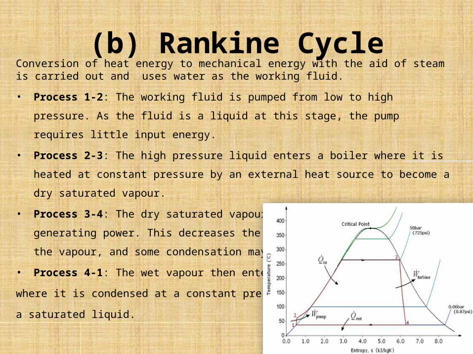
(b) Rankine Cycle
Conversion of heat energy to mechanical energy with the aid of steam is carried out and uses water as the working fluid.
• Process 1-2: The working fluid is pumped from low to high pressure. As the fluid is a liquid at this
stage, the pump requires little input energy.
• Process 2-3: The high pressure liquid enters a boiler where it is heated at constant pressure by an
external heat source to become a dry saturated vapour.
• Process 3-4: The dry saturated vapour expands through a turbine, generating power. This decreases
the temperature and pressure of the vapour, and some condensation may occur.
• Process 4-1: The wet vapour then enters a condenser
where it is condensed at a constant pressure to become
a saturated liquid.
5.GAS TURBINE STARTING SYSTEM1. The function of the starting system is to crank the gas turbine
up to the required speed until it becomes self-sustaining.
2. starting large gas turbine is by using a motor driven hydraulic starting system.
3. GTG can be started by using a frequency converter to rotate the generator which drives the turbine for starting.
4. Black Start system :-
-- Consist of a separate diesel engine or a gas turbine driven synchronous generator connected to station switch gear bus
-- To start a gas turbine in the event of AC-power failure an emergency black start system is provided.
-- It also helps in safe coasting down of the gas turbine .
-- It supply the total auxiliary power required to start a gas turbine from stand still condition
6. FUEL SYSTEM• Gas turbines are capable of burning a range of fuels including:-
naphthalene ,distillates, crude oils and natural gas .• Liquid fuel system :-
-- system consists of the liquid fuel storage and handling .
-- The liquid fuel storage and handling system provides means for unloading , storage and distribution of the fuel oil within the plant.
-- It is Composed of the following major components:-
• Fuel oil unloading pumps
• Fuel oil transfer pumps
• Fuel oil storage tanks
• Flow meter
• Strainers
• Pressure and Level control stations and Distribution piping.
• Fuel oil may be supplied to the plant by a pipeline, oil barrages, oil tankers, rail/road or high way trucks.
• Fuel gas system consists of the
(a) Off base system
(b) On base system
• Naphtha forwarding system:-
-- Forwarding system is mainly remote controlled from the GTLCR and CCR.
-- Possibility to control the main devices locally by a switching the selector switch on local position in the local panel.
Combined Cycles
Basically of two types :-
(1) Unfired combined cycle :-
- exhaust gas is used only for raising steam to be fed to the steam turbine for power generation
- Dual Pressure Cycles more heat is recovered in the HRSG
- steam with higher pressure and temperature can be generated.
(2) Fully Fired Combined Cycle :- system the heat of exhaust gas from gas turbine is used for purposes .
- Heat contained in exhaust gas is used to heat feed water to a desire.
HOW DOES A COMBINE POWER PLANT WORK?
POWER GENERATION
1. Air Inlet • Air needed for combustion is 800, 000 cubic feet per minute.• At air inlet section where it is cleaned, cooled and controlled,
in order to reduce noise.
2. TURBINE – GENERATOR• Air enters the gas turbine where it is compressed, mixed with
natural gas and ignited, which causes it to expand.• Pressure spins the turbine blades, which are attached to a shaft
and a generator, creating electricity.• Each gas turbine produces 185 megawatts (MW)of electricity.
3.Heat Recovery Steam Generator (HRSG)• Hot exhaust gas exits the turbine at about 1100 degrees
Fahrenheit and then passes through Heat Recovery Steam Generator (HRSG)
• 18 layers of 100-foot tall tube bundles, filled with high purity water.
• Hot exhaust gas coming from the turbines passes through these tube bundles, which act like a radiator, boiling the water inside the tubes, and turning that water into steam.
• The gas then exits the power plant through the exhaust stack at a much cooler 180 degrees.
• About 1 million pounds of steam per hour is generated in this way and sent over to the steam turbine through overhead piping.
4. Steam Turbine• A Siemens Wasting house KN Turbine Generator, capable of
producing up to 240 MW. • It is located on top of the condenser, across from the cooling
tower.• Steam enters the turbine with temperatures as high as 1000
degrees Fahrenheit and pressure as strong as 2,200 pounds per square inch.
• The residual steam leaves the turbine at low pressure and low heat, about 100 degrees.
• Exhaust steam passes into a condenser, to be turned back into water.
• By using this “combined-cycle” process, two gas turbines and one steam turbine, we can produce a total of about 600 megawatts of electricity.
5.Emissions Control
Selective Catalytic Reduction (SCR)• To control the emissions in the exhaust gas so that it remains
within permitted levels as it enters the atmosphere, the exhaust gas passes through two catalysts located in the HRSG.
• controls Carbon Monoxide (CO) emissions and the other catalyst controls Oxides of Nitrogen, (NOx) emissions.
Best Available Control Technology (BACT)• Our annual average concentration of NOx is only2 parts per
million, which is considered the “best available control technology.
• The exhaust stack is only 145 feet high, compared to500 feet, the height required by older power plants that use less efficient emission technology.
6. Condenser and Cooling Tower • The purpose of the condenser to turn low energy steam back
into pure water for use in the Heat Recovery Steam Generator.• The purpose of the cooling tower is to cool the circulating
water that passes through the condenser. • We process and treat the Title 22 recycled water after receiving
it from the City, before using it in our cooling tower.• The cool basin water absorbs all of the heat from the residual
steam after being exhausted from the steam turbine and it is then piped back to the top of the cooling tower.
• The cool water drops into the basin, hot water goes out of the stacks.
• The cooling tower evaporates about three-fourth of the processed, recycled water, then we send about one-fourth of it back through the sewer lines for re-treatment by the City.
7. Water Tanks• Largest tank is the Service Water tank that contains 470,000 gallons of water to be
used for drinking, firefighting and for the high purity water train.• water from the service water tank is pumped to the water treatment building .• where it then passes through a reverse osmosis unit, a membrane de-carbonator, and
mixed resin bed demineralizers to produce up to 400 gallons per minute of ultra-pure water.
• pure water is then stored in the smaller 365,000-gallon tank until it is turned into steam for making electricity.
8. Natural Gas• Natural gas fuels the combustion turbines.• Each turbine can consume up to 2,000 MMBTU per hour.• Gas compressors pump the natural gas though the facilities’ fuel gas system where it
is delivered to the gas turbine.• The HRSG duct burners at the proper temperature, pressure and purity.