Page 1
Westinghouse Non Proprietary Class 3 © 2017 Westinghouse Electric Company LLC. All Rights Reserved.
1
Pete Mickus, Director Inside Sales – Tranter Inc.
Jim Sechrist, Manager, Market Application – Westinghouse Electric Company, LLC
Presentation to Feedwater System Reliability Users Group
January 18, 2017
Page 2
2
Westinghouse Non Proprietary Class 3 © 2017 Westinghouse Electric Company LLC. All Rights Reserved.
Agenda
Topic Presenter
Introductions J. Sechrist
SPFWH Description J. Sechrist
SPFWH Prototype Testing P. Mickus
SPFWH Maintenance & P. Mickus
& Servicing Schemes
Questions All
Page 3
Westinghouse Non Proprietary Class 3 © 2017 Westinghouse Electric Company LLC. All Rights Reserved.
3
Shell & Plate Low Pressure FWH
Page 4
4
Westinghouse Non Proprietary Class 3 © 2017 Westinghouse Electric Company LLC. All Rights Reserved.
• Addresses Shell and Tube FWH
design challenges of:
– Component degradation due
to FIV and FAC
– Limited shell and tube side
access
– Loss of system thermal and
hydraulic performance over
time
Shell & Plate Feedwater HeaterDescription
Westinghouse Electric Company and Tranter Inc. have collaborated to
develop the modular, low-pressure, horizontal Shell and Plate
Feedwater Heater (SPFWHTM) heat exchanger product
Page 5
5
Westinghouse Non Proprietary Class 3 © 2017 Westinghouse Electric Company LLC. All Rights Reserved.
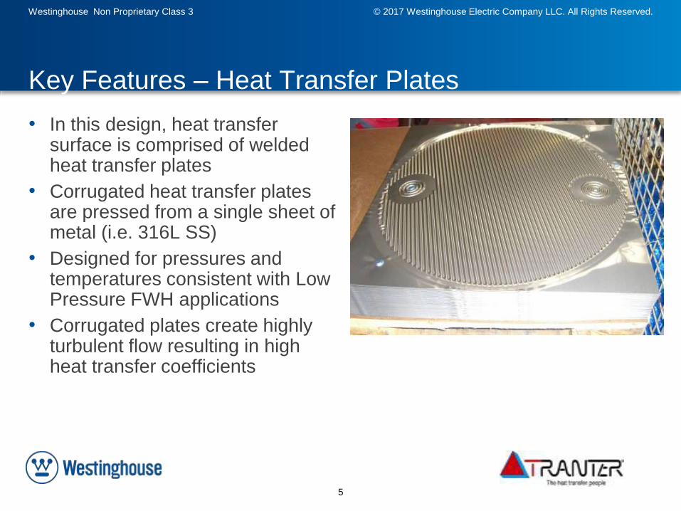
• In this design, heat transfer surface is comprised of welded heat transfer plates
• Corrugated heat transfer plates are pressed from a single sheet of metal (i.e. 316L SS)
• Designed for pressures and temperatures consistent with Low Pressure FWH applications
• Corrugated plates create highly turbulent flow resulting in high heat transfer coefficients
Key Features – Heat Transfer Plates
Page 6
6
Westinghouse Non Proprietary Class 3 © 2017 Westinghouse Electric Company LLC. All Rights Reserved.
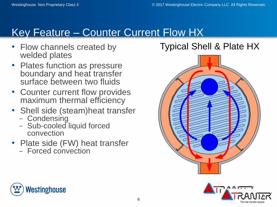
Key Feature – Counter Current Flow HX
• Flow channels created by welded plates
• Plates function as pressure boundary and heat transfer surface between two fluids
• Counter current flow provides maximum thermal efficiency
• Shell side (steam)heat transfer- Condensing- Sub-cooled liquid forced
convection
• Plate side (FW) heat transfer- Forced convection
Typical Shell & Plate HX
Page 7
7
Westinghouse Non Proprietary Class 3 © 2017 Westinghouse Electric Company LLC. All Rights Reserved.
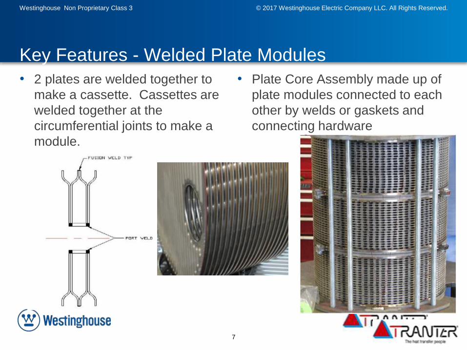
• 2 plates are welded together to
make a cassette. Cassettes are
welded together at the
circumferential joints to make a
module.
Key Features - Welded Plate Modules
• Plate Core Assembly made up of
plate modules connected to each
other by welds or gaskets and
connecting hardware
Page 8
8
Westinghouse Non Proprietary Class 3 © 2017 Westinghouse Electric Company LLC. All Rights Reserved.
Design Advantage – Resistance to common
degradation mechanisms
• Reduced potential for common degradation mechanisms
• Potential for Flow Accelerated Corrosion (FAC) is minimized by selecting high quality alloy materials
–Stainless steel (316L) plates–0.1% chrome material used in all areas susceptible to FAC
• Potential for Flow Induced Vibration (FIV) is significantly reduced due to a heat transfer plate geometry that features tightly‐spaced, corrugated plate‐to‐plate contact points which are typically less than ~ 0.5” apart. This configuration is fundamentally different than “long span” supported tubes.
Page 9
9
Westinghouse Non Proprietary Class 3 © 2017 Westinghouse Electric Company LLC. All Rights Reserved.
Westinghouse and Tranter Present a New
Feedwater Heater Design
Modular Low Pressure Shell and Plate Feedwater Heater (SPFWH)
Removable Head
Feedwater Outlet Nozzle
Replaceable Heat Transfer Plates
Drain Outlet Nozzle
Extraction Steam Nozzle
Drain Inlet Nozzles
Feedwater Inlet Nozzle
Full Access to Shell for Inspection
Extraction Steam Nozzle
Page 10
10
Westinghouse Non Proprietary Class 3 © 2017 Westinghouse Electric Company LLC. All Rights Reserved.
• Welded heat transfer plates replace tubes
• Common degradation mechanisms (FIV & FAC) are minimized due to plate geometry and material selection
• Component inspection and maintenance is improved because removable head provides easy access to plates and shell
• Long-term performance is improved since heat transfer plates can be easily replaced
Key Features/Differentiators
SPFWHRelevant Experience, Key Features, & Innovation
• Design represents an extension of existing Tranter Shell & Plate heat exchangers of which Tranter has sold over 7000
• Prototype fabricated and tested to validate the functionality of design and benchmark correlations
• Documented in ASME 2014 Power Conference paper: Power2014-32248
• Developed SPFWH design to meet specifications for AP1000 LPFWH No 3A/B and 4A/B
– Smaller footprint – (11ft - 14 ft length)– Approximately 30% lower cost– Under consideration for use in future
AP1000 plants
WEC/Tranter Experience
Page 11
Westinghouse Non Proprietary Class 3 © 2017 Westinghouse Electric Company LLC. All Rights Reserved.
11
SPFWH - Prototype Testing
Page 12
12
Westinghouse Non Proprietary Class 3 © 2017 Westinghouse Electric Company LLC. All Rights Reserved.
Prototype Test Objectives
• Provide a test demonstration of the major design concepts
in an integrated scale model test.
• Provide experimental validation of design tools used for
prediction of overall performance.
• Tests performed included:– Hydrostatic Test
– Heat-up / Cool-down Test
– Level Test
– Vent Test
– Nominal Design Condition Test
– Abnormal Design Condition Test
– Fatigue Test
Page 13
13
Westinghouse Non Proprietary Class 3 © 2017 Westinghouse Electric Company LLC. All Rights Reserved.
Prototype Design
Parameter Prototype
Plate Model Number SPW-40
Plate Material 316L Stainless Steel
Outer diameter of plate,
mm (in.)
440 (17.3)
Port diameter of plate,
mm (in.)
80 (3.1)
Plate thickness, mm (in.) 0.6 (0.024)
Number of modules 3
Flow configuration Counter-current flow
Page 14
14
Westinghouse Non Proprietary Class 3 © 2017 Westinghouse Electric Company LLC. All Rights Reserved.
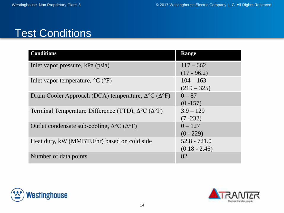
Test Conditions
Conditions Range
Inlet vapor pressure, kPa (psia) 117 – 662
(17 - 96.2)
Inlet vapor temperature, °C (°F) 104 – 163
(219 – 325)
Drain Cooler Approach (DCA) temperature, ∆°C (∆°F) 0 – 87
(0 -157)
Terminal Temperature Difference (TTD), ∆°C (∆°F) 3.9 – 129
(7 -232)
Outlet condensate sub-cooling, ∆°C (∆°F) 0 – 127
(0 - 229)
Heat duty, kW (MMBTU/hr) based on cold side 52.8 - 721.0
(0.18 - 2.46)
Number of data points 82
Page 15
15
Westinghouse Non Proprietary Class 3 © 2017 Westinghouse Electric Company LLC. All Rights Reserved.
Conclusions
• The prototype test program objectives have been met.
• The test results:– demonstrate that the close thermal approaches required of a
high performing feedwater heater are achievable with a
properly sized SPFWH™ heat exchanger in an appropriately
designed and operated feedwater system
– indicate that the SPFWH™ heat exchanger design is a viable
alternative to a shell-and-tube type heat exchanger due to the
performance, compactness, modularity, and robustness of the
new design.
Page 16
Westinghouse Non Proprietary Class 3 © 2017 Westinghouse Electric Company LLC. All Rights Reserved.
16
SPFWH Maintenance and Servicing Schemes
Page 17
17
Westinghouse Non Proprietary Class 3 © 2017 Westinghouse Electric Company LLC. All Rights Reserved.
1/31/2017 17
Leak Detection
Drain
Note: Leakage during operation is
determined via use of level control
alarm in shell to detect feedwater
breach into Condensing section
• Depressurize system and
drain vessel and plate pack
• Remove spool pieces
Page 18
18
Westinghouse Non Proprietary Class 3 © 2017 Westinghouse Electric Company LLC. All Rights Reserved.
1/31/2017 18
Leak Detection
• Install blind flanges with dripless disconnects
• Perform high pressure test – check cross leakage on shell side inspection port
• If leak is present remove core and perform soap bubble test
Page 19
19
Westinghouse Non Proprietary Class 3 © 2017 Westinghouse Electric Company LLC. All Rights Reserved.
1/31/2017 19
Core Removal
• Remove head bolts
• Pull crane used to remove
core
• Install rail extensions
Page 20
20
Westinghouse Non Proprietary Class 3 © 2017 Westinghouse Electric Company LLC. All Rights Reserved.
1/31/2017 20
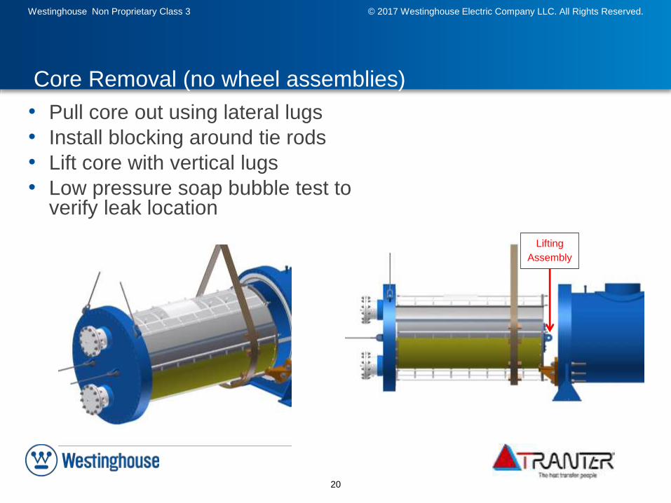
Core Removal (no wheel assemblies)
• Pull core out using lateral lugs
• Install blocking around tie rods
• Lift core with vertical lugs
• Low pressure soap bubble test to verify leak location
Lifting
Assembly
Page 21
21
Westinghouse Non Proprietary Class 3 © 2017 Westinghouse Electric Company LLC. All Rights Reserved.
1/31/2017 21
Core Removal (with roller assembies)
• Loosen nuts on all tie rods.
• Slide clamping plate away from core assembly to provide room for module movement.
• Remove tie rods on top half of the unit.
• Use jacking bolts to separate the last module from the core assembly.
• Repeat module movement as required to provide access to the module to be repaired / replaced.
• Remove module from core assembly
• Service or replace module as appropriate.
• Reverse steps, replacing any gaskets associated with modules that have been separated.
• Reassemble clamping plate and tie rods.
• Perform visual inspection on unit.
• Perform low pressure air and soap bubble test.
• Install new head flange gasket.
Page 22
22
Westinghouse Non Proprietary Class 3 © 2017 Westinghouse Electric Company LLC. All Rights Reserved.
1/31/2017 22
Module Removal/Replacement
Note: The modular design allows removal of any plate module without breaking any welds, or if fully welded, connecting joints between modules contain a small, circumferential weld that can be ground and rewelded in a short amount of time
Page 23
23
Westinghouse Non Proprietary Class 3 © 2017 Westinghouse Electric Company LLC. All Rights Reserved.
• How would the plates be cleaned, if
necessary? What is the process to clean and the
cost?– Plates can be cleaned at site or sent to Tranter
Service Center for cleaning
1/31/2017 23
Core Cleaning
Hydroblast
Page 24
24
Westinghouse Non Proprietary Class 3 © 2017 Westinghouse Electric Company LLC. All Rights Reserved.
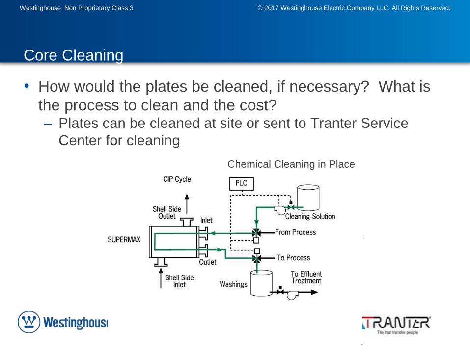
• How would the plates be cleaned, if necessary? What is
the process to clean and the cost?– Plates can be cleaned at site or sent to Tranter Service
Center for cleaning
1/31/2017 24
Core Cleaning
Chemical Cleaning in Place
Page 25
25
Westinghouse Non Proprietary Class 3 © 2017 Westinghouse Electric Company LLC. All Rights Reserved.
Based upon ~ 5000 Units in service have 1-2 failures/year. Therefore overall failure rate = 0.05%
Given average unit has ~ 80 plates even if all failures were plate failures = .001% of plates
1/31/2017 25
Failure Rates
Page 26
26
Westinghouse Non Proprietary Class 3 © 2017 Westinghouse Electric Company LLC. All Rights Reserved.
• There are no gaskets in Shell & Plate that provide with reaction forces during compression of the gaskets
– ~30% gasket compression
• Shell & Plate use very low compression forces to prepare for welding
• During final assembly of the core, approximately 100 tons of compressive force ensure 100% metal to metal contact of all plates
1/31/2017 26
Distortion of Plates
Free standing
welded plate pack
Compressed plate
pack
Page 27
27
Westinghouse Non Proprietary Class 3 © 2017 Westinghouse Electric Company LLC. All Rights Reserved.
• Design pressures and temperatures are consistent with
Low Pressure Feedwater Heater applications
– Maximum design pressure for shell and plate feedwater
heater is as follows:• Fully welded – 1000F
• Modular welded – 1000F
• Modular gasketed – 366F
1/31/2017 27
Maximum Design Temperature
Page 28
28
Westinghouse Non Proprietary Class 3 © 2017 Westinghouse Electric Company LLC. All Rights Reserved.
• What is the Plate and Shell side Delta P?– Plate side Delta P (feedwater) – 13.2 psi allowed and 5.94
psi calculated
– Shell side Delta P – (steam) – 5.6 psi allowed and 2.2 psi
calculated
1/31/2017 28
Maximum Pressure Drops
Page 29
29
Westinghouse Non Proprietary Class 3 © 2017 Westinghouse Electric Company LLC. All Rights Reserved.
• Is there a concern on fouling of the plates?– Feedwater heater system is non-biological (clean water
coming in). Given this and the fact that there are high flow
velocities and turbulent flow in plates, fouling is not a
concern
– Maximum Particle Size – Shell and plate heat exchangers
feature tightly spaced, corrugated channels that develop
high heat transfer rates. As such, particle size is limited to
50% of the plate gap. Plate gap for this proposal is 2.1mm
and therefore the maximum particle size is 1.0mm
1/31/2017 29
Fouling
Page 30
Westinghouse Non Proprietary Class 3 © 2017 Westinghouse Electric Company LLC. All Rights Reserved.
30
Wrap Up & Discussion