All shut-off fittings can be secured onto walls, racks (72 mm grid) and vertical and horizontal pipes.
This offers the advantage when assembling a plant that the shut-off fittings can be secured first and the lines for the medium and differential pressure connected to them. It is then possible to check all connections for leaks and to blow out or flush the pipes in order to remove dirt (welding residues, shavings etc.).
The measuring instruments can be screwed onto the shut-off fit-tings right at the end when all piping has been completed.
If an instrument has to be removed for maintenance, the fittings and pipes remain as they are. It is only necessary to close the valves – the instrument can then be removed, and refitted follow-ing maintenance.
Classification according to pressure equipment directive (PED 97/23/EC):
For gases of fluid group 1 and liquids of fluid group 1; compli-ance with requirements of article 3, paragraph 3 (sound engi-neering practice).
New standard IEC 61518
The flange connection between transmitter and valve manifold was modified in the new standard IEC 61518. The only connec-tion thread approved for use in the process flanges of the pres-sure transmitter is 7/16-20 UNF.
The valve manifolds for M12 screws, including the accessory sets, have therefore been deleted.
Material acceptance test certificate to EN 10204-3.1
If a material acceptance test certificate to EN 10204-3.1 is re-quired when ordering valve manifolds or shut-off fittings, please note that a single certificate is sufficient for each ordered item type. This means that you will only be charged for one certificate in the cost calculations.
■ Pressure transmitters with shut-off fittings - mounting examples
SITRANS P transmitter for gauge pressure with double shut-off valve, SITRANS P pressure transmitter with multiway cock or 3-spindle valve manifold
SITRANS P transmitter for differential pressure with 3-way valve manifold, 3-spindle valve manifold or valve manifold combination DN 5/DN 8
SITRANS P pressure transmitter for differential pressure, mounted in pro-tective box (available on request)
SITRANS P pressure transmitter mounted on valve combination "Mono-flange" for direct connection to flanges (available on request)
FI01_2015_en_kap01.book Seite 258 Mittwoch, 8. Oktober 2014 10:12 10
Pressure MeasurementFitttings - Shut-off valves for gauge and absolute pressure transmitters
Shut-off valves to DIN 16270, DIN 16271 and DIN 162721
■ Overview
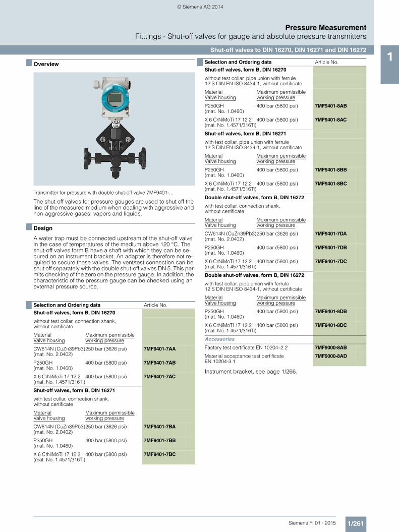
Transmitter for pressure with double shut-off valve 7MF9401-...
The shut-off valves for pressure gauges are used to shut off the line of the measured medium when dealing with aggressive and non-aggressive gases, vapors and liquids.
■ Design
A water trap must be connected upstream of the shut-off valve in the case of temperatures of the medium above 120 °C. The shut-off valves form B have a shaft with which they can be se-cured on an instrument bracket. An adapter is therefore not re-quired to secure these valves. The vent/test connection can be shut off separately with the double shut-off valves DN 5. This per-mits checking of the zero on the pressure gauge. In addition, the characteristic of the pressure gauge can be checked using an external pressure source.
Instrument bracket, see page 1/266.
Selection and Ordering data Article No.Shut-off valves, form B, DIN 16270
without test collar, connection shank, without certificate
MaterialValve housing
Maximum permissibleworking pressure
CW614N (CuZn39Pb3)(mat. No. 2.0402)
250 bar (3626 psi) 7MF9401-7AA
P250GH(mat. No. 1.0460)
400 bar (5800 psi) 7MF9401-7AB
X 6 CrNiMoTi 17 12 2 (mat. No. 1.4571/316Ti)
400 bar (5800 psi) 7MF9401-7AC
Shut-off valves, form B, DIN 16271
with test collar, connection shank, without certificate
MaterialValve housing
Maximum permissibleworking pressure
CW614N (CuZn39Pb3)(mat. No. 2.0402)
250 bar (3626 psi) 7MF9401-7BA
P250GH(mat. No. 1.0460)
400 bar (5800 psi) 7MF9401-7BB
X 6 CrNiMoTi 17 12 2(mat. No. 1.4571/316Ti)
400 bar (5800 psi) 7MF9401-7BC
Shut-off valves, form B, DIN 16270
without test collar, pipe union with ferrule12 S DIN EN ISO 8434-1, without certificate
MaterialValve housing
Maximum permissibleworking pressure
P250GH(mat. No. 1.0460)
400 bar (5800 psi) 7MF9401-8AB
X 6 CrNiMoTi 17 12 2(mat. No. 1.4571/316Ti)
400 bar (5800 psi) 7MF9401-8AC
Shut-off valves, form B, DIN 16271
with test collar, pipe union with ferrule12 S DIN EN ISO 8434-1, without certificate
MaterialValve housing
Maximum permissibleworking pressure
P250GH(mat. No. 1.0460)
400 bar (5800 psi) 7MF9401-8BB
X 6 CrNiMoTi 17 12 2(mat. No. 1.4571/316Ti)
400 bar (5800 psi) 7MF9401-8BC
Double shut-off valves, form B, DIN 16272
with test collar, connection shank, without certificate
MaterialValve housing
Maximum permissibleworking pressure
CW614N (CuZn39Pb3)(mat. No. 2.0402)
250 bar (3626 psi) 7MF9401-7DA
P250GH(mat. No. 1.0460)
400 bar (5800 psi) 7MF9401-7DB
X 6 CrNiMoTi 17 12 2(mat. No. 1.4571/316Ti)
400 bar (5800 psi) 7MF9401-7DC
Double shut-off valves, form B, DIN 16272
with test collar, pipe union with ferrule12 S DIN EN ISO 8434-1, without certificate
MaterialValve housing
Maximum permissibleworking pressure
P250GH(mat. No. 1.0460)
400 bar (5800 psi) 7MF9401-8DB
X 6 CrNiMoTi 17 12 2(mat. No. 1.4571/316Ti)
400 bar (5800 psi) 7MF9401-8DC
Accessories
Factory test certificate EN 10204–2.2 7MF9000-8AB
Material acceptance test certificate EN 10204-3.1
7MF9000-8AD
Selection and Ordering data Article No.
FI01_2015_en_kap01.book Seite 261 Mittwoch, 8. Oktober 2014 10:12 10
Pressure MeasurementFitttings - Shut-off valves for gauge and absolute pressure transmitters
Double shut-off valves1
■ Overview
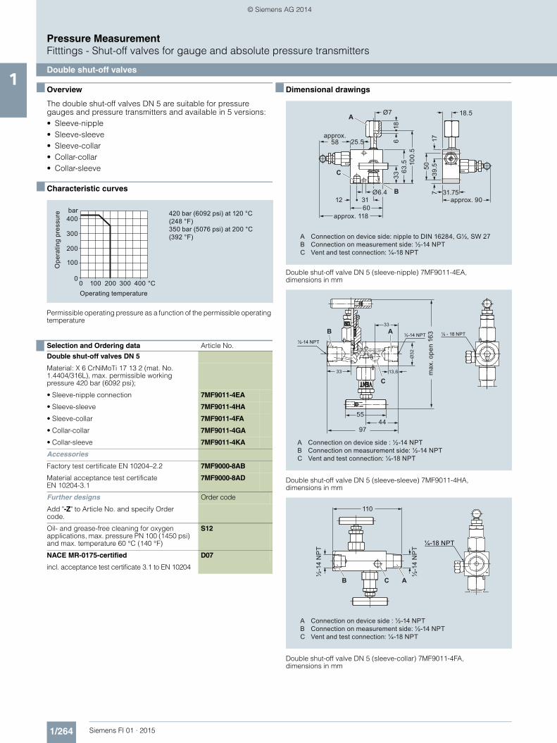
The double shut-off valves DN 5 are suitable for pressure gauges and pressure transmitters and available in 5 versions:• Sleeve-nipple• Sleeve-sleeve• Sleeve-collar• Collar-collar• Collar-sleeve
■ Characteristic curves
Permissible operating pressure as a function of the permissible operating temperature
■ Dimensional drawings
Double shut-off valve DN 5 (sleeve-nipple) 7MF9011-4EA, dimensions in mm
Double shut-off valve DN 5 (sleeve-sleeve) 7MF9011-4HA,dimensions in mm
Double shut-off valve DN 5 (sleeve-collar) 7MF9011-4FA, dimensions in mm
Selection and Ordering data Article No.Double shut-off valves DN 5
Material: X 6 CrNiMoTi 17 13 2 (mat. No. 1.4404/316L), max. permissible working pressure 420 bar (6092 psi);
• Sleeve-nipple connection 7MF9011-4EA
• Sleeve-sleeve 7MF9011-4HA
• Sleeve-collar 7MF9011-4FA
• Collar-collar 7MF9011-4GA
• Collar-sleeve 7MF9011-4KA
Accessories
Factory test certificate EN 10204–2.2 7MF9000-8AB
Material acceptance test certificate EN 10204-3.1
7MF9000-8AD
Further designs Order code
Add "-Z" to Article No. and specify Order code.
Oil- and grease-free cleaning for oxygen applications, max. pressure PN 100 (1450 psi) and max. temperature 60 °C (140 °F)
S12
NACE MR-0175-certified D07
incl. acceptance test certificate 3.1 to EN 10204
420 bar (6092 psi) at 120 °C (248 °F)350 bar (5076 psi) at 200 °C (392 °F)
Operating temperature
Ope
ratin
g pr
essu
re bar400
300
200
100
0400 °C3002001000
A Connection on device side: nipple to DIN 16284, G½, SW 27B Connection on measurement side: ½-14 NPTC Vent and test connection: ¼-18 NPT
approx. 90
approx. 118
approx. 58
Ø6.4
63.5 10
0.5
31.75
18.5
25.5
39.5
12 31
336
18
50
B
C
60
717
AØ7
¼ - 18 NPT
5544
97
½-14 NPT
Ø32
33 13,6
33
½-14 NPTB
C
A
A Connection on device side : ½-14 NPTB Connection on measurement side: ½-14 NPTC Vent and test connection: ¼-18 NPT
max
. ope
n 16
3
A Connection on device side : ½-14 NPTB Connection on measurement side: ½-14 NPTC Vent and test connection: ¼-18 NPT
110
½-1
4 N
PT
B C A
½-1
4 N
PT
¼-18 NPT
FI01_2015_en_kap01.book Seite 264 Mittwoch, 8. Oktober 2014 10:12 10
Pressure MeasurementFitttings - Shut-off valves for gauge and absolute pressure transmitters
Accessories for shut-off valves/double shut-off valves1
■ Overview
The mounting set is suitable for the double shut-off valves 7MF9011-4.A and for wall, rack and pipe mounting.
■ Dimensional drawings
Mounting bracket (7MF9011-8AB) for shut-off valves 7MF9011-4DA and 7MF9011-4EA for wall, rack or pipe mounting, dimensions in mm
Mounting bracket (7MF9011-8AC) for shut-off valves 7MF9011-4FA and 7MF9011-4GA for wall, rack or pipe mounting, dimensions in mm
■ Overview
The instrument brackets are needed to mount the following units:• Pressure gauges with threaded connection at the bottom• Shut-off valves to DIN 16270, DIN 16271 and DIN 16272
(7MF9401-7.. and 7MF9401-8..)
■ Dimensional drawings
Instrument bracket form H, for wall mounting, M56340-A0046/-A0047,dimensions in mm
Instrument bracket form A, wall or pipe mounting,M56340-A0053/-A0079, dimensions in mm
Selection and Ordering data Article No.Mounting set for shut-off valves
• 7MF9011-4DA und -4EAmade of stainless steel, scope of delivery:1x mounting bracket, 2x hexagon screws M6x40, 1x mounting clip, 2x washers 8.4 to DIN 125;2x hexagon nuts 8.4 to DIN EN 24032
7MF9011-8AB
• 7MF9011-4FA und -4GAmade of stainless steel, scope of delivery:1x mounting bracket, 2x hexagon screws M6x10, 1x mounting clip, 2x washers 8.4 to DIN 125;2x hexagon nuts 8.4 to DIN EN 24032
7MF9011-8AC
SW 1085
Ø60,3 100
65 90
R30
7225
90
Ø11
50 724
6,5
SW 10
85Ø60,3 100
7290
R30
7225 90
Ø115065
46,
5
Selection and Ordering data Article No.Instrument bracket, form H, DIN 16281
(e.g. for gauge)made of aluminium alloy, painted black,for wall mounting, screw-type bracket cover• Projection length 60 mm M56340-A0046• Projection length 100 mm M56340-A0047
Instrument bracket, form A, DIN 16281
(e.g. for transmitter)made of annealed cast iron, galvanized and primed for mounting on a wall or rack or or on a sectional rail (horizontal/vertical); Screw-type bracket cover
M56340-A0053
Instrument bracket, form A, DIN 16281
(e.g. for transmitter)made of annealed cast iron, galvanized and primed with pipe clamp for wall and pipe mounting (horizotal/vertical)Screw-type bracket cover
M56340-A0079
56
28
(60)100
(160)
18
Ø26
h11
1065
Ø7
85
28100
91
72
Ø26
h11
1072
≤ Ø63
34
M8
Ø11
FI01_2015_en_kap01.book Seite 266 Mittwoch, 8. Oktober 2014 10:12 10
Pressure MeasurementFitttings - Shut-off valves for differential pressure transmitters
2-, 3- and 5-spindle valve manifolds DN 51
■ Overview
The 2-spindle, 3-spindle and 5-spindle valve manifolds 7MF9411-5.. are for pressure transmitters for absolute pressure or differential pressure.
The valve manifolds are used to shut off the differential pressure lines and to check the pressure transmitter zero.
The 2-spindle and the 5-spindle valve manifold enable in addi-tion venting on the transmitter side and checking of the pressure transmitter characteristic.
■ Benefits
• Max. working pressure 420 bar (6092 psi)• Each available in version for oxygen
■ Application
The spindle valve manifolds DN 5 are designed for liquids and gases.
Each is available in a version for oxygen on request.
■ Design
All versions of the valve manifolds have a process connection ½-14 NPT. The connection for the pressure transmitter is always designed as a flange connection to IEC 61518, form B . The 2-spindle and the 5-spindle valve manifold have in addition a vent and test connection ¼-18 NPT.
The valves have an external spindle thread.
Materials used
■ Function
Functions of all valve manifolds:• Shutting off the differential pressure lines• Checking the pressure transmitter zero
Additional functions of the 2-spindle and 5-spindle valve mani-folds through the vent and test connection:• Venting on the transmitter side• Checking the pressure transmitter characteristic
Component Material Mat. No.
Housing X 2 CrNiMo 17 13 2 1.4404/316L
Cones X 6 CrNiMoTi 17 12 2 1.4571/316Ti
Spindles X 2 CrNiMo 18 10 1.4404/316L
Head parts X 5 CrNiMo 18 10 1.4401/316
Packings PTFE -
Selection and Ordering data Article No.Valve manifolds DN 5 7 M F 9 4 1 1 - 77A
Click on the Article No. for the online confi-guration in the PIA Life Cycle Portal.
for liquids and gases, for flanging to pressure transmitters for absolute and differential pressure, max. working pressure 420 bar (order accessory set with Order code),without certificate
• 2-spindle valve manifold 5 A
• 3-spindle valve manifold 5 B
• 5-spindle valve manifold 5 C
Accessories
Factory test certificate EN 10204–2.2 7MF9000-8AB
Material acceptance test certificate EN 10204-3.1
7MF9000-8AD
Selection and Ordering data Order code Article No.Further designs1)
Please add "-Z" to Article No. and specify Order code.
Accessory set to EN(connection between valve manifold and pressure transmitter)
for valve manifold 7MF9411-5A.
2x screws 7/16-20 UNF x 1¾ inch to ASME B18.2.1; chromized steel1x gasket made of PTFE, max. permissible 420 bar (6092 psi), 80 °C (176 °F)
K35 7MF9411-7DB
2x screws 7/16-20 UNF x 1¾ inch to ASME B18.2.1; stainless steel1x gasket made of PTFE, max. permissible 420 bar (6092 psi), 80 °C (176 °F)
K45 7MF9411-7DC
for valve manifold 7MF9411-5B. and -5C.
4x screws 7/16-20 UNF x 1¾ inch to ASME B18.2.1; chromized steel2x flat gaskets made of PTFE, max. permissible 420 bar (6092 psi), 80 °C (176 °F)
K36 7MF9411-5DB
4x screws 7/16-20 UNF x 1¾ inch to ASME B18.2.1; stainless steel2x flat gaskets made of PTFE, max. permissible 420 bar (6092 psi), 80 °C (176 °F)
K46 7MF9411-5DC
Accessory set to DIN2)
(connection between valve manifold and pressure transmitter)
for valve manifold 7MF9411-5A.
2x screws M10x45 to DIN EN 24014; chromized steel2x washers Ø 10.5 mm to DIN 125;1x gasket made of PTFE, max. permissible 420 bar (6092 psi), 80 °C (176 °F)
K15 7MF9411-7BB
2x screws M10x45 to DIN EN 24014; stainless steel2x washers Ø 10.5 mm to DIN 125, stainless steel;1x gasket made of PTFE, max. permissible 420 bar (6092 psi), 80 °C (176 °F)
K25 7MF9411-7BC
FI01_2015_en_kap01.book Seite 267 Mittwoch, 8. Oktober 2014 10:12 10
Pressure MeasurementFitttings - Shut-off valves for differential pressure transmitters
2-, 3- and 5-spindle valve manifolds DN 51
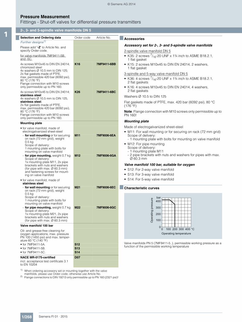
■ Accessories
Accessory set for 2-, 3- and 5-spindle valve manifolds
2-spindle valve manifold DN 5 • K35: 2 screws 7/16-20 UNF x 1¾ inch to ASME B18.2.1,
1 flat gasket• K15: 2 screws M10x45 to DIN EN 24014, 2 washers,
1 flat gasket
3-spindle and 5-way valve manifold DN 5 • K36: 4 screws 7/16-20 UNF x 1¾ inch to ASME B18.2.1,
2 flat gaskets• K16: 4 screws M10x45 to DIN EN 24014, 4 washers,
2 flat gaskets
Washers Ø 10.5 to DIN 125
Flat gaskets made of PTFE, max. 420 bar (6092 psi), 80 °C (176 °F)
Note: Flange connection with M10 screws only permissible up to PN 160!
Mounting plate
Made of electrogalvanized sheet-steel• M11: For wall mounting or for securing on rack (72 mm grid)
Scope of delivery: - 1 mounting plate with bolts for mounting on valve manifold
• M12: For pipe mountingScope of delivery: - 1 mounting plate M11- 2 pipe brackets with nuts and washers for pipes with max.
Ø 60.3 mm
Valve manifold 100 bar, suitable for oxygen• S12: For 2-way valve manifold• S13: For 3-way valve manifold• S14: For 5-way valve manifold
■ Characteristic curves
Valve manifolds PN 5 (7MF9411-5..), permissible working pressure as a function of the permissible working temperature
for valve manifolds 7MF9411-5B. and -5C.
4x screws M10x45 to DIN EN 24014; chromized steel4x washers Ø 10.5 mm to DIN 125;2x flat gaskets made of PTFE, max. permissible 420 bar (6092 psi), 80 °C (176 °F)Flange connection with M10 screws only permissible up to PN 160.
K16 7MF9411-6BB
4x screws M10x45 to DIN EN 24014; stainless steel4x washers Ø 10.5 mm to DIN 125, stainless steel;2x flat gaskets made of PTFE, max. permissible 420 bar (6092 psi), 80 °C (176 °F)Flange connection with M10 screws only permissible up to PN 160.
K26 7MF9411-6BC
Mounting plate
• for valve manifold, made of electrogalvanized sheet-steel- for wall mounting or for securing
on rack (72 mm grid), weight 0.5 kgScope of delivery:1 mounting plate with bolts for mounting on valve manifold
M11 7MF9006-6EA
- for pipe mounting, weight 0.7 kgScope of delivery:1x mounting plate M11, 2x pipe brackets with nuts and washers (for pipe with max. Ø 60.3 mm) and fastening screws for mount-ing on valve manifold
M12 7MF9006-6GA
• for valve manifold, made of stainless steel- for wall mounting or for securing
on rack (72 mm grid), weight 0.5 kgScope of delivery:1 mounting plate with bolts for mounting on valve manifold
M21 7MF9006-6EC
- for pipe mounting, weight 0.7 kgScope of delivery:1x mounting plate M21, 2x pipe brackets with nuts and washers (for pipe with max. Ø 60.3 mm)
M22 7MF9006-6GC
Valve manifold 100 bar
Oil- and grease-free cleaning for oxygen applications, max. pressure PN 100 (1450 psi) and max. temper-ature 60 °C (140 °F)• for 7MF9411-5A. S12• for 7MF9411-5B. S13• for 7MF9411-5C. S14
NACE MR-0175-certified D07incl. acceptance test certificate 3.1 to EN 10204
1) When ordering accessory set or mounting together with the valve manifolds, please use Order code; otherwise use Article No.
2) Flange connections to DIN 19213 only permissible up to PN 160 (2321 psi)!
Selection and Ordering data Order code Article No.Further designs1)
Please add "-Z" to Article No. and specify Order code.
Operating temperature
Ope
ratin
g pr
essu
re bar400
300
200
100
0400 °C3002001000
FI01_2015_en_kap01.book Seite 268 Mittwoch, 8. Oktober 2014 10:12 10
The multiway cock PN 100 (1450 psi) can be flanged to pressure transmitters for differential pressure.
■ Benefits
• Version available for aggressive liquids, gases and vapors• Robust design• Oil-free and grease-free version possible• One-hand operation
■ Application
The PN 100 (1450 psi) multiway cock is available in versions for aggressive and non-aggressive liquids, gases and vapors.
■ Design
The multiway cock can be flanged with four screws to pressure transmitters for differential pressure.
The PN 100 (1450 psi) has 2 process connections and one blow-out connection. A steel version of the multiway cock is available for non-aggressive media, and a stainless steel version for ag-gressive media. The housing is forged in one piece. The switch-ing lever is removable.
Sealing can be improved during operation.
Note: An accessory set is always required for flanging of the multiway cock to a differential pressure transmitter.
■ Function
• Shutting off the differential pressure lines• Blowing out the differential pressure lines• Testing the pressure transmitter zero
Cock positions; the symbols are printed on the cock
■ Technical specifications
Test Operation Blow out Line 2
Blow out Line 1
1
5
2
3 4
1
5
2
3 4
1
5
2
3 4
1
5
2
3 4
Multiway cocks PN 100
Measured medium Water, non-aggressive liquids and gases
Aggressive liquids, gases and vapors
Material P250GH, mat. No.: 1.0460
X 6 CrNiMoTi 17 12 2, mat. No. 1.4571/316Ti
Connections Steel, for pipe Ø 12 mm, L series
Stainless steel, for pipe Ø 12 mm, L series
• Process connection 2 bulkhead glands• Connection for blow-
ing outPipe union with ferrule
Max. permissible working temperature
200 °C (392 °F)
Max. permissible working pressure
100 bar (1450 psi) (up to max. 60 °C (140 °F))
Weight 2.5 kg
Selection and Ordering data Article No.Multiway cock PN 100 (1450 psi) 7 M F 9 0 0 4 - 77A
Click on the Article No. for the online confi-guration in the PIA Life Cycle Portal.
for flanging to pressure transmitters, weight 2.5 kg (without accessory set), without certificate
For water and non-aggressive gases and vapors 1 P
For aggressive liquids, gases and vapors 1 Q
Accessories
Factory test certificate EN 10204–2.2 7MF9000-8ABMaterial acceptance test certificate EN 10204-3.1 7MF9000-8AD
Selection and Ordering data Order code Article No.Further designs1)
Please add "-Z" to Article No. and spec-ify Order code.
1) When ordering accessory set or mounting together with the multiway cock, please use Order code; otherwise use Article No.
Accessory set to EN(required for flanging, weight 0.2 kg)4x screws 7/16-20 UNF x 1 inch to ASME B18.2.1; chromized steel2x gaskets made of PTFE, max. permissible temperature 80 °C (176 °F)
L31 7MF9004-5CC
Accessory set to DIN(required for flanging, weight 0.2 kg)4x screws M10x25 to DIN EN 24017; chro-mized steel, 4x washers Ø 10.5 mm to DIN 125; 2x gaskets made of PTFE, max. permissible temperature 80 °C (176 °F)
• Standard design L11 7MF9004-6AD• Version for oxygen (together with Or-
der code S11L15 7MF9004-6AE
Multiway cock in oil-free and grease-free design
Oil- and grease-free cleaning for oxy-gen applications, max. pressure PN 100 (1450 psi) and max. temperature 60 °C (140 °F), BAM-tested lubricant, gasket suitable for oxygen measure-ment (only with Article No. 7MF9004–1Q.Z)
S11
Mounting bracketRequired for wall mounting or for securing on rack (72 mm grid), made of electrogalvanized sheet-steel, weight 0.85 kg
M13 7MF9004-6AA
NACE MR-0175-certified D07incl. acceptance test certificate 3.1 to EN 10204 (only available for version 7MF9004-1QA)
FI01_2015_en_kap01.book Seite 270 Mittwoch, 8. Oktober 2014 10:12 10
Pressure MeasurementFitttings - Shut-off valves for differential pressure transmitters
3-way and 5-way valve manifolds DN 51
■ Overview
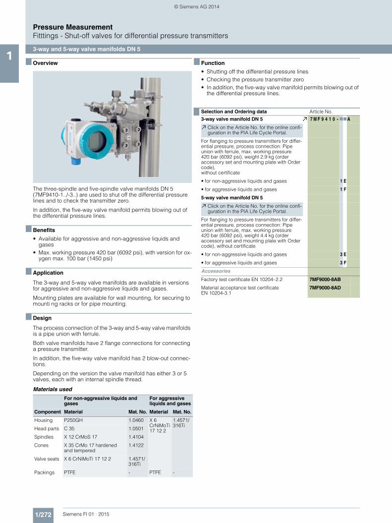
The three-spindle and five-spindle valve manifolds DN 5 (7MF9410-1../-3..) are used to shut off the differential pressure lines and to check the transmitter zero.
In addition, the five-way valve manifold permits blowing out of the differential pressure lines.
■ Benefits
• Available for aggressive and non-aggressive liquids and gases
• Max. working pressure 420 bar (6092 psi), with version for ox-ygen max. 100 bar (1450 psi)
■ Application
The 3-way and 5-way valve manifolds are available in versions for aggressive and non-aggressive liquids and gases.
Mounting plates are available for wall mounting, for securing to mounti ng racks or for pipe mounting.
■ Design
The process connection of the 3-way and 5-way valve manifolds is a pipe union with ferrule.
Both valve manifolds have 2 flange connections for connecting a pressure transmitter.
In addition, the five-way valve manifold has 2 blow-out connec-tions.
Depending on the version the valve manifold has either 3 or 5 valves, each with an internal spindle thread.
Materials used
■ Function
• Shutting off the differential pressure lines• Checking the pressure transmitter zero• In addition, the five-way valve manifold permits blowing out of
the differential pressure lines.
For non-aggressive liquids and gases
For aggressive liquids and gases
Component Material Mat. No. Material Mat. No.
Housing P250GH 1.0460 X 6 CrNiMoTi17 12 2
1.4571/316Ti
Head parts C 35 1.0501
Spindles X 12 CrMoS 17 1.4104
Cones X 35 CrMo 17 hardened and tempered
1.4122
Valve seats X 6 CrNiMoTi 17 12 2 1.4571/316Ti
Packings PTFE - PTFE -
Selection and Ordering data Article No.3-way valve manifold DN 5 7 M F 9 4 1 0 - 77A
Click on the Article No. for the online confi-guration in the PIA Life Cycle Portal.
For flanging to pressure transmitters for differ-ential pressure, process connection: Pipe union with ferrule, max. working pressure 420 bar (6092 psi), weight 2.9 kg (order accessory set and mounting plate with Order code),without certificate
• for non-aggressive liquids and gases 1 E
• for aggressive liquids and gases 1 F
5-way valve manifold DN 5
Click on the Article No. for the online confi-guration in the PIA Life Cycle Portal.
For flanging to pressure transmitters for differ-ential pressure, process connection: Pipe union with ferrule, max. working pressure 420 bar (6092 psi), weight 4.4 kg (order accessory set and mounting plate with Order code), without certificate
• for non-aggressive liquids and gases 3 E
• for aggressive liquids and gases 3 F
Accessories
Factory test certificate EN 10204–2.2 7MF9000-8AB
Material acceptance test certificate EN 10204-3.1
7MF9000-8AD
FI01_2015_en_kap01.book Seite 272 Mittwoch, 8. Oktober 2014 10:12 10
Pressure MeasurementFitttings - Shut-off valves for differential pressure transmitters
3-way and 5-way valve manifolds DN 51
■ Accessories
Accessory set for 3-way and 5-way valve manifold DN 5 for flanging• B31: 4 screws 7/16-20 UNF x 21/8 inch to ASME B18.2.1,
2 flat gaskets• B34: 4 screws 7/16-20 UNF x 21/8 inch to ASME B18.2.1,
2 O-rings (FPM 90)• B11: 4 screws M10x55 to DIN EN 24014, 4 washers,
2 flat gaskets• B15 (suitable for oxygen): 4 screws M10x55 to DIN EN 24014,
4 washers, 2 flat gaskets• B16: 4 screws M10x55 to DIN EN 24014, 4 washers,
2 O-rings (FPM 90)
Washers Ø 10.5 to DIN 125
Flat gaskets made of PTFE, max. 420 bar (6092 psi), 80 °C (176 °F)
O-ring to DIN 3771, 20 x 2.65 – S – FPM90, max. 420 bar (6092 psi), 120 °C (248 °F)
Note: M10 screws only permissible up to PN 160 (2320 psi)!
Mounting plate
Made of electrogalvanized sheet-steel• M11: For wall mounting or for securing on rack (72 mm grid)
Scope of delivery: - 1 mounting plate 7MF9006-6EA with bolts for mounting on
valve manifold• M12: For pipe mounting
Scope of delivery: - 1 mounting plate M11- 2 pipe brackets with nuts and washers for pipes with max.
Ø 60.3 mm
Valve manifold 100 bar, suitable for oxygen
S12: Only in combination with versions for aggressive liquids and gases
Selection and Ordering data Order code Article No.Further designs1)
1) When ordering accessory set or mounting together with the valve manifolds, please use Order code; otherwise use Article No.
Please add "-Z" to Article No. and specify Order code.
Accessory set to EN(required for flanging, weight 0.2 kg)
4x screws 7/16-20 UNF x 21/8 inch to ASME B18.2; chromized steel2x flat gaskets made of PTFE, max. permissible 420 bar (6092 psi), 80 °C (176 °F)
B31 7MF9010-5CC
4x screws 7/16-20 UNF x 21/8 inch to ASME B18.2; chromized steel2x O-rings to DIN 3771, 20 x 2.65 - S - FPM90, max. permissble 420 bar (6092 psi), 120 °C (248 °F)
B34 7MF9410-5CA
Accessory set to DIN2)
2) Flange connections to DIN 19213 only permissible up to PN 160 (2321 psi)
(required for flanging, weight 0.2 kg)
4x screws M10x55 to DIN EN 24014; chromized steel4x washers Ø 10.5 mm to DIN 125;2x flat gaskets made of PTFE, max. permissible 420 bar (6092 psi), 80 °C (176 °F)
• Standard design B11 7MF9010-6AD
• Version for oxygen B15 7MF9010-6AE
4x screws M10x55 to DIN EN 24014; chromized steel4x washers Ø 10.5 mm to DIN 125;2x O-rings to DIN 3771, 20 x 2.65 - S - FPM90, max. permissble 420 bar (6092 psi), 120 °C (248 °F)
B16 7MF9010-6CC
Mounting platefor valve manifold, made of electrogalvanized sheet-steelfor wall mounting or for securing on rack (72 mm grid), weight 0.5 kgScope of delivery:1 mounting plate with bolts for mounting on valve manifold
M11 7MF9006-6EA
for pipe mounting, weight 0.7 kgScope of delivery:1x mounting plate M11, 2x pipe brackets with nuts and washers (for pipe with max. Ø 60.3 mm)
M12 7MF9006-6GA
Valve manifold 100 barsuitable for oxygen
for 7MF9410-1F S13
for 7MF9410-3F S14
NACE MR-0175-certified D07incl. acceptance test certificate 3.1 to EN 10204 (only available for ver-sion 7MF9410-1FA and -3FA)
FI01_2015_en_kap01.book Seite 273 Mittwoch, 8. Oktober 2014 10:12 10
Pressure MeasurementFitttings - Shut-off valves for differential pressure transmitters
3-way valve manifold DN 81
■ Overview
The 3-way valve manifold DN 8 (7MF9416-1../-2..) is for pressure transmitters for differential pressure. It is used to shut off and blow out differential pressure lines and to test the pressure trans-mitter zero.
In the designs with a test connection, a test device can be con-nected to test the pressure transmitter characteristic.
■ Benefits
• For aggressive and non-aggressive liquids and gases• The maximum working pressure is 420 bar (6092 psi).
■ Application
The 3-way valve manifold is available in versions for aggressive and non-aggressive liquids and gases.
Mounting plates are available for wall mounting, for securing to mounting racks or for pipe mounting.
■ Design
For the process connection on the version for non-aggressive media it is possible to choose between a pipe union with ferrule and welding pins.
The version for aggressive media always has a pipe union with ferrule.
Both versions are available optionally with a test connection M20x1.5.
The valves have an internal spindle thread.
Materials used
■ Function
The 3-way valve manifold DN 8 performs two functions as stan-dard:• Shutting off the differential pressure lines• Checking the pressure transmitter zero
All versions are also available with a test connection, to which a test device for checking the pressure transmitter characteristic can be connected.
For non-aggressive liquids and gases
For aggressive liquids and gases
Component Material Mat. No. Material Mat. No.
Housing P250GH 1.0460 X 6 CrNiMoTi17 12 2
1.4571/316Ti
Head parts C 35 1.0501
Spindles X 12 CrMoS 17 1.4104
Cones X 35 CrMo 17 hard-ened and tempered
1.4122
Valve seats X 6 CrNiMoTi 17 12 2 1.4571/316Ti
Packings PTFE - PTFE -
Selection and Ordering data Article No.3-way valve manifold DN 8 7 M F 9 4 1 6 - 77A
Click on the Article No. for the online confi-guration in the PIA Life Cycle Portal.
For flanging to pressure transmitters for differ-ential pressure, max. working pressure 420 bar (6092 psi), (order accessory set and mounting plate with Order code), without cer-tificate
For non-aggressive liquids and gasesprocedss connection: Pipe union with ferrule Ø 12 mm
• without test connection 1 B
• with test connection 1 C
For non-aggressive liquids and gasesprocedss connection: Welding pin Ø 14 x 2.5
• without test connection 2 C
• with test connection 2 D
For aggressive liquids and gasesprocess connection: Pipe union with ferrule Ø 12 mm
• without test connection 1 D
• with test connection 1 E
Accessories
Factory test certificate EN 10204–2.2 7MF9000-8AB
Material acceptance test certificate EN 10204-3.1
7MF9000-8AD
FI01_2015_en_kap01.book Seite 275 Mittwoch, 8. Oktober 2014 10:12 10
Pressure MeasurementFitttings - Shut-off valves for differential pressure transmitters
3-way valve manifold DN 81
■ Accessories
Accessory set for 3-way valve manifold DN 8 for flanging• B31: 4 screws 7/16-20 UNF x 21/8 inch to ASME B18.2.1,
2 flat gaskets• B34: 4 screws 7/16-20 UNF x 21/8 inch to ASME B18.2.1,
2 O-rings (FPM 90)• B11: 4 screws M10x55 to DIN EN 24014, 4 washers,
2 flat gaskets• B16: 4 screws M10x55 to DIN EN 24014, 4 washers,
2 O-rings (FPM 90)
Washers Ø 10.5 to DIN 125
Flat gaskets made of PTFE, max. 420 bar (6092 psi), 80 °C (176 °F)
O-ring to DIN 3771, 20 x 2.65 – S – FPM90, max. 420 bar (6092 psi), 120 °C (248 °F)
Note: M10 screws only permissible up to PN 160 (2320 psi)!
Mounting plate
Made of electrogalvanized sheet-steel• M11: For wall mounting or for securing on rack (72 mm grid)
Scope of delivery: - 1 mounting plate with bolts for mounting on valve manifold
• M12: For pipe mountingScope of delivery: - 1 mounting plate M11- 2 pipe brackets with nuts and washers for pipes with max.
Ø 60.3 mm
■ Characteristic curves
3-way valve manifold DN 8, permissible working pressure as a function of the permissible working temperature
Selection and Ordering data Order code Article No.Further designs1)
1) When ordering accessory set or mounting together with the valve manifold, please use Order code; otherwise use Article No.
Please add "-Z" to Article No. and specify Order code.
Accessory set to EN(required for flanging, weight 0.2 kg)
4x screws 7/16-20 UNF x 21/8 inch to ASME B18.2;chromized steel2x flat gaskets made of PTFE, max. permissible 420 bar (6092 psi), 80 °C (176 °F)
B31 7MF9010-5CC
4x screws 7/16-20 UNF x 21/8 inch to ASME B18.2; chromized steel2x O-rings to DIN 3771, 20 x 2.65 - S - FPM90, max. permiss-ble 420 bar (6092 psi), 120 °C (248 °F)
B34 7MF9410-5CA
Accessory set to DIN2)
2) Flange connections to DIN 19213 only permissible up to PN 160 (2321 psi)!
(required for flanging, weight 0.2 kg)
4x screws M10x55 to DIN EN 24014; chromized steel4x washers Ø 10.5 mm to DIN 125;2x flat gaskets made of PTFE, max. permissible 420 bar (6092 psi), 80 °C (176 °F)
B11 7MF9010-6AD
4x screws M10x55 to DIN EN 24014; chromized steel4x washers Ø 10.5 mm to DIN 125;2x O-rings to DIN 3771, 20 x 2.65 - S - FPM90, max. permiss-ble 420 bar (6092 psi), 120 °C (248 °F)
B16 7MF9010-6CC
Mounting plateFor valve manifold, made of electrogalvanized sheet-steel
for wall mounting or for securing on rack (72 mm grid), weight 0.5 kgScope of delivery:1 mounting plate with bolts for mounting on valve manifold
M11 7MF9006-6EA
for pipe mounting, weight 0.7 kgScope of delivery:1x mounting plate M11, 2x pipe brackets with nuts and washers (for pipe with max. Ø 60.3 mm)
M12 7MF9006-6GA
NACE MR-0175-certified D07incl. acceptance test certificate 3.1 to EN 10204 (only available for ver-sion 7MF9416-1DA and -1EA)
Operating temperature
Ope
ratin
g pr
essu
re bar400
300
200
100
0400 °C3002001000
FI01_2015_en_kap01.book Seite 276 Mittwoch, 8. Oktober 2014 10:12 10
Pressure MeasurementFitttings - Shut-off valves for differential pressure transmitters
Valve manifold combination DN 5/DN 81
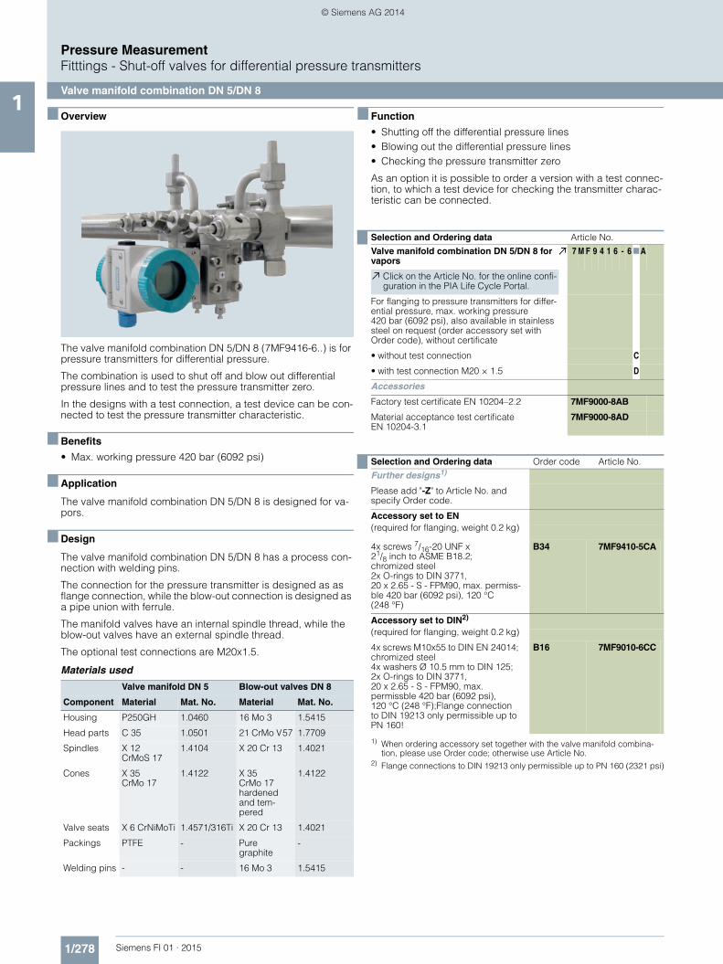
■ Overview
The valve manifold combination DN 5/DN 8 (7MF9416-6..) is for pressure transmitters for differential pressure.
The combination is used to shut off and blow out differential pressure lines and to test the pressure transmitter zero.
In the designs with a test connection, a test device can be con-nected to test the pressure transmitter characteristic.
■ Benefits
• Max. working pressure 420 bar (6092 psi)
■ Application
The valve manifold combination DN 5/DN 8 is designed for va-pors.
■ Design
The valve manifold combination DN 5/DN 8 has a process con-nection with welding pins.
The connection for the pressure transmitter is designed as as flange connection, while the blow-out connection is designed as a pipe union with ferrule.
The manifold valves have an internal spindle thread, while the blow-out valves have an external spindle thread.
The optional test connections are M20x1.5.
Materials used
■ Function
• Shutting off the differential pressure lines• Blowing out the differential pressure lines• Checking the pressure transmitter zero
As an option it is possible to order a version with a test connec-tion, to which a test device for checking the transmitter charac-teristic can be connected.
Valve manifold DN 5 Blow-out valves DN 8
Component Material Mat. No. Material Mat. No.
Housing P250GH 1.0460 16 Mo 3 1.5415
Head parts C 35 1.0501 21 CrMo V57 1.7709
Spindles X 12 CrMoS 17
1.4104 X 20 Cr 13 1.4021
Cones X 35 CrMo 17
1.4122 X 35 CrMo 17 hardened and tem-pered
1.4122
Valve seats X 6 CrNiMoTi 1.4571/316Ti X 20 Cr 13 1.4021
Packings PTFE - Pure graphite
-
Welding pins - - 16 Mo 3 1.5415
Selection and Ordering data Article No.Valve manifold combination DN 5/DN 8 for vapors
7 M F 9 4 1 6 - 6 7A
Click on the Article No. for the online confi-guration in the PIA Life Cycle Portal.
For flanging to pressure transmitters for differ-ential pressure, max. working pressure 420 bar (6092 psi), also available in stainless steel on request (order accessory set with Order code), without certificate
• without test connection C
• with test connection M20 × 1.5 D
Accessories
Factory test certificate EN 10204–2.2 7MF9000-8AB
Material acceptance test certificate EN 10204-3.1
7MF9000-8AD
Selection and Ordering data Order code Article No.Further designs1)
1) When ordering accessory set together with the valve manifold combina-tion, please use Order code; otherwise use Article No.
Please add "-Z" to Article No. and specify Order code.
Accessory set to EN(required for flanging, weight 0.2 kg)
4x screws 7/16-20 UNF x 21/8 inch to ASME B18.2; chromized steel2x O-rings to DIN 3771, 20 x 2.65 - S - FPM90, max. permiss-ble 420 bar (6092 psi), 120 °C (248 °F)
B34 7MF9410-5CA
Accessory set to DIN2)
2) Flange connections to DIN 19213 only permissible up to PN 160 (2321 psi)
(required for flanging, weight 0.2 kg)
4x screws M10x55 to DIN EN 24014; chromized steel4x washers Ø 10.5 mm to DIN 125;2x O-rings to DIN 3771, 20 x 2.65 - S - FPM90, max. permissble 420 bar (6092 psi), 120 °C (248 °F);Flange connection to DIN 19213 only permissible up to PN 160!
B16 7MF9010-6CC
FI01_2015_en_kap01.book Seite 278 Mittwoch, 8. Oktober 2014 10:12 10
Pressure MeasurementFitttings - Shut-off valves for differential pressure transmitters
Valve manifold combination DN 5/DN 81
■ Accessories
Accessory set for valve manifold combination DN 5/DN 8 for flanging• B34: 4 screws 7/16-20 UNF x 21/8 inch to ASME B18.2.1,
2 O-rings (FPM 90)• B16: 4 screws M10x55 to DIN EN 24014, 4 washers,
2 O-rings (FPM 90)
Washers Ø 10.5 to DIN 125
O-ring to DIN 3771, 20 x 2.65 - S – FPM90, max. 420 bar (6092 psi), 120 °C (248 °F)
Note: M10 screws only permissible up to PN 160 (2321 psi)!
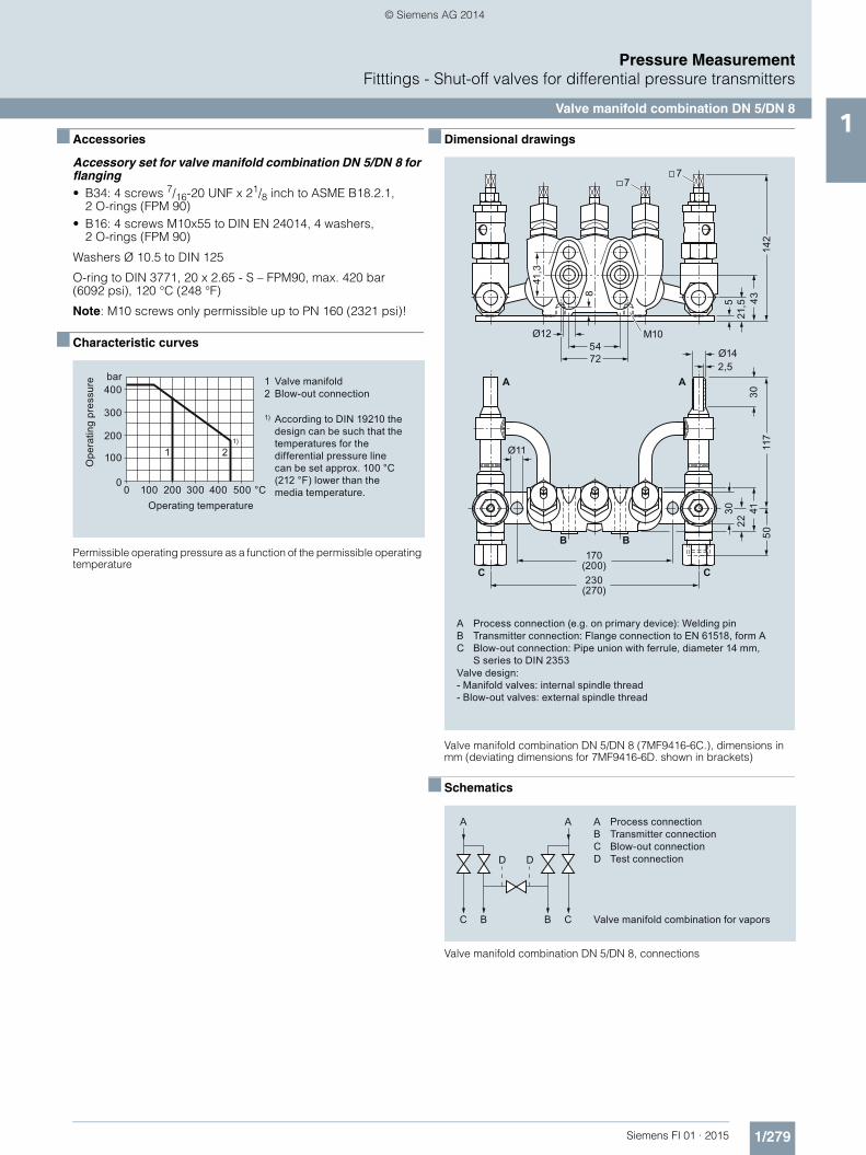
■ Characteristic curves
Permissible operating pressure as a function of the permissible operating temperature
■ Dimensional drawings
Valve manifold combination DN 5/DN 8 (7MF9416-6C.), dimensions in mm (deviating dimensions for 7MF9416-6D. shown in brackets)
■ Schematics
Valve manifold combination DN 5/DN 8, connections
Valve manifold
According to DIN 19210 the design can be such that the temperatures for the differential pressure line can be set approx. 100 °C (212 °F) lower than the media temperature.
1Blow-out connection2
1)
Operating temperature
Ope
ratin
g pr
essu
re bar400
300
200
100
0400 °C300200100
11)
0 500
2
A Process connection (e.g. on primary device): Welding pinB Transmitter connection: Flange connection to EN 61518, form AC Blow-out connection: Pipe union with ferrule, diameter 14 mm,
S series to DIN 2353Valve design: - Manifold valves: internal spindle thread- Blow-out valves: external spindle thread
54
8
41,3
5041
3022
30
72
77
230(270)
170(200)
Ø14
Ø11
2,5
M10Ø12
A A
B
C C
B
117
43
21,55
142
AB
D
Process connectionTransmitter connection
Test connectionC Blow-out connection
Valve manifold combination for vaporsC
A
B C
A
B
DD
FI01_2015_en_kap01.book Seite 279 Mittwoch, 8. Oktober 2014 10:12 10
Pressure MeasurementFitttings - Shut-off valves for differential pressure transmitters
Valve manifold combination DN 81
■ Overview
The valve manifold combination DN 8 (7MF9416-4..) is for pres-sure transmitters for differential pressure.
It is used to shut off and blow out the differential pressure lines and to check the pressure transmitter zero.
In the designs with a test connection, a test device can be con-nected to check the pressure transmitter characteristic.
■ Benefits
• Max. working pressure 420 bar (6092 psi)
■ Application
The valve manifold combination DN 8 is designed for vapors.
■ Design
The valve manifold combination DN 8 has a process connection with welding pins.
The connection for the pressure transmitter is designed as as flange connection, while the blow-out connection is designed as a pipe union with ferrule.
The manifold valves have an internal spindle thread, while the blow-out valves have an external spindle thread.
The optional test connection is M20x1.5.
The valve manifold combination DN 8 is supplied with a mount-ing plate.
Materials used
■ Function
• Shutting off the differential pressure lines• Blowing out the differential pressure lines• Checking the pressure transmitter zero
As an option it is possible to order a version with a test connec-tion, to which a test device for checking the pressure transmitter characteristic can be connected.
■ Accessories
Accessory set for valve manifold combination DN 8 for flanging• B34: 4 screws 7/16-20 UNF x 21/8 inch to ASME B 18.2.1,
2 O-rings (FPM 90)• B16: 4 screws M10x55 to DIN EN 24014, 4 washers,
2 O-rings (FPM 90)
Washers Ø 10.5 to DIN 125
O-ring to DIN 3771, 20 x 2.65 – S – FPM90, max. 420 bar (6092 psi), 120 °C (248 °F)
Note: M10 screws only permissible up to PN 160 (2321 psi)!
Valve manifold Blow-out valves
Component Material Mat. No. Material Mat. No.
Housing P250GH 1.0460 16 Mo 3 1.5415
Head parts C 35 1.0501 21 CrMo V57 1.7709
Spindles X 12 CrMoS 17
1.4104 X 20 Cr 13 1.4021
Cones X 35 CrMo 17
1.4122 X 35 CrMo 17 hardened and tem-pered
1.4122
Valve seats X 6 CrNiMoTi 1.4571/316Ti X 20 Cr 13 1.4021
Packings PTFE - Pure graphite
-
Welding pins - - 16 Mo 3 1.5415
Selection and Ordering data Article No.Valve manifold combination DN 8 for vapors
7 M F 9 4 1 6 - 77A
Click on the Article No. for the online confi-guration in the PIA Life Cycle Portal.
for flanging to pressure transmitters for differ-ential pressure, with mounting plate, max. working pressure 420 bar (6092 psi), also available in stainless steel on request (order accessory set with Order code), without certif-icate
• without test connection 4 C
• with test connection M20 × 1.5 4 D
Accessories
Factory test certificate EN 10204–2.2 7MF9000-8AB
Material acceptance test certificate EN 10204-3.1
7MF9000-8AD
Selection and Ordering data Order code Article No.Further designs1)
1) When ordering accessory set together with the valve manifold combination, please use Order code; otherwise use Article No.
Please add "-Z" to Article No. and specify Order code.
Accessory set to EN(required for flanging, weight 0.2 kg)
4x screws 7/16-20 UNF x21/8 inch to ASME B18.2; chromized steel2x O-rings to DIN 3771, 20 x 2.65 - S - FPM90, max. permissble 420 bar (6092 psi), 120 °C (248 °F)
B34 7MF9410-5CA
Accessory set to DIN2)
2) Flange connections to DIN 19213 only permissible up to PN 160 (2321 psi)
(required for flanging, weight 0.2 kg)
4x screws M10x55 to DIN EN 24014; chromized steel4x washers Ø 10.5 mm to DIN 125;2x O-rings to DIN 3771, 20 x 2.65 - S - FPM90, max. permissble 420 bar (6092 psi), 120 °C (248 °F)Flange connection to DIN 19 213 only permissible up to PN 160!
B16 7MF9010-6CC
FI01_2015_en_kap01.book Seite 280 Mittwoch, 8. Oktober 2014 10:12 10
Pressure MeasurementFitttings - Shut-off valves for differential pressure transmitters
Valve manifold combination DN 81
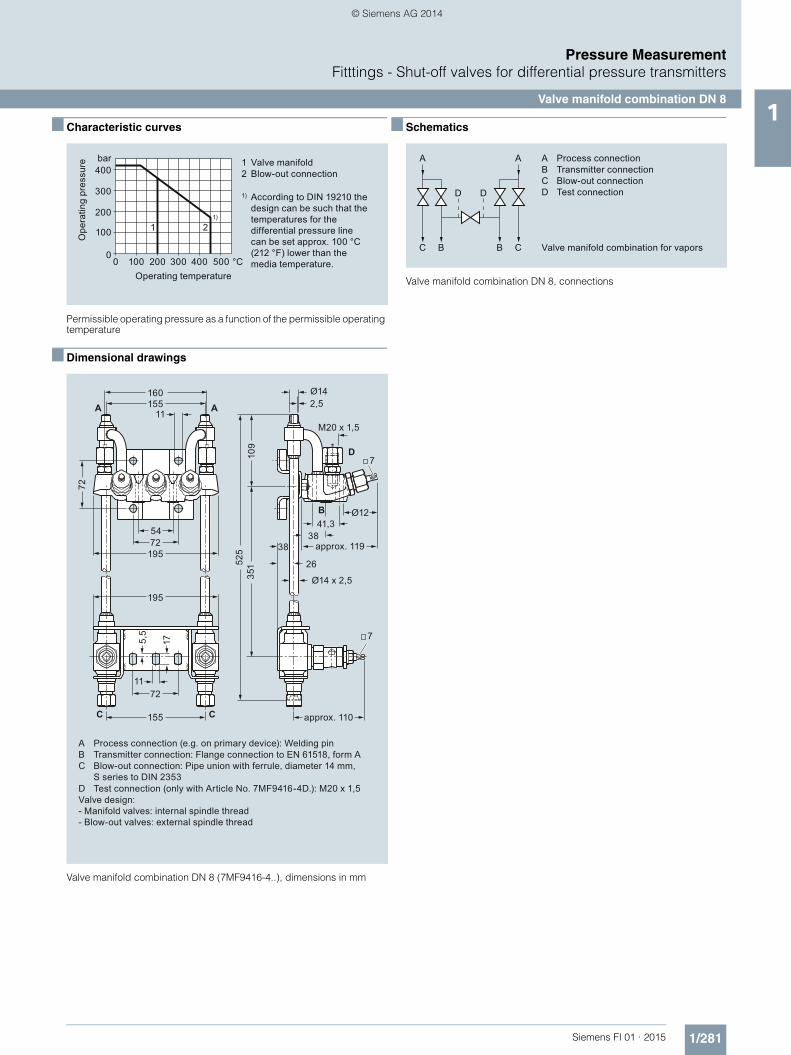
■ Characteristic curves
Permissible operating pressure as a function of the permissible operating temperature
■ Dimensional drawings
Valve manifold combination DN 8 (7MF9416-4..), dimensions in mm
■ Schematics
Valve manifold combination DN 8, connections
Valve manifold
According to DIN 19210 the design can be such that the temperatures for the differential pressure line can be set approx. 100 °C (212 °F) lower than the media temperature.
1Blow-out connection2
1)
Operating temperature
Ope
ratin
g pr
essu
re bar400
300
200
100
0400 °C300200100
11)
0 500
2
A Process connection (e.g. on primary device): Welding pinB Transmitter connection: Flange connection to EN 61518, form A
D Test connection (only with Article No. 7MF9416-4D.): M20 x 1,5
C Blow-out connection: Pipe union with ferrule, diameter 14 mm, S series to DIN 2353
Pressure MeasurementFitttings - Shut-off valves for differential pressure transmitters
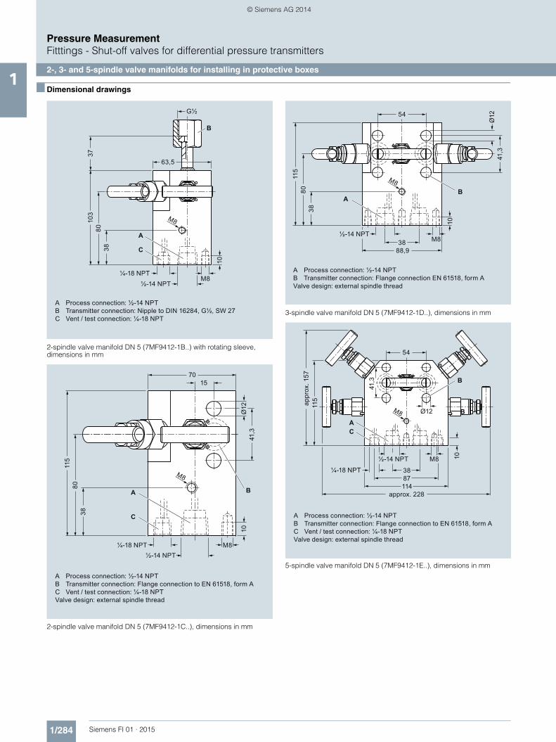
2-, 3- and 5-spindle valve manifolds for installing in protective boxes1
■ Overview
The 2-spindle, 3-spindle and 5-spindle valve manifolds (7MF9412-1..) are used to shut off the differential pressure lines and to check the transmitter zero.
The five-spindle valve manifold permits venting on the transmit-ter side and checking of the transmitter characteristic.
These valve manifolds are preferentially used when mounting in protective boxes. In addition, they can also be used for wall, frame or pipe mounting together with the mounting bracket.
Transmitters of the DS series can be operated and read from the front when using these valve manifolds.
■ Application
The valve manifolds DN 5 are designed for liquids and vapors and for installing in protective boxes.
Each is available in a version for oxygen on request
■ Design
All versions of the spindle manifolds have a process connection ½-14 NPT.
The connection for the pressure transmitter is always designed as a flange connection to IEC 61518, Form A.
The 2-spindle and the 5-spindle valve manifold have in addition a vent and test connection ¼-18 NPT.
The valves have an external spindle thread.
Materials used
■ Functions
Functions of all valve manifolds:• Shutting off the differential pressure lines• Checking the pressure transmitter zero
Additional functions of the 2-spindle and 5-spindle valve mani-folds through the vent and test connection:• Venting on the transmitter side• Checking the pressure transmitter characteristic
Components Material Mat. No.
Housing X 2 CrNiMo 17 13 2 1.4404/316L
Cones X 6 CrNiMoTi 17 12 2 1.4571/316Ti
Spindles X 2 CrNiMo 18 10 1.4404/316L
Head parts X 5 CrNiMo 18 10 1.4401/316
Packings PTFE -
Selection and Ordering data Article No.Valve manifolds DN 5 for mounting in protective boxes
7 M F 9 4 1 2 - 77A
Click on the Article No. for the online confi-guration in the PIA Life Cycle Portal.
for liquids and gasesfor flanging to pressure transmitters for absolute and differential pressureMaterial: stainless steel, mat. No: 1.4404/316Lmax. working pressure 420 bar (6092 psi)(order accessory set with Order code),without certificate
• 2-spindle valve manifold with rotatng sleeve G½
1 B
• 2-spindle valve manifold with flange connection
1 C
• 3-spindle valve manifold 1 D
• 5-spindle valve manifold 1 E
Accessories
Factory test certificate EN 10204–2.2 7MF9000-8AB
Material acceptance test certificate EN 10204-3.1
7MF9000-8AD
Selection and Ordering data Order code Article No.Further designs1)
Please add "-Z" to Article No. and specify Order code.
Accessory set to EN(connection between valve manifold and pressure transmitter)
for valve manifold 7MF9412–1C.
2x screws 7/16-20 UNF x 2 inch to ASME B18.2.1; chromized steel1x O-ring to DIN 3771, 20 x 2.65 - S - FPM90, max. permissble 420 bar(6092 psi), 120 °C (248 °F)
F32 7MF9412-6CA
2x screws 7/16-20 UNF x 2 inch to ASME B18.2.1; chromized steel1x gasket made of PTFE, max. permissible 420 bar (6092 psi), 80 °C (176 °F)2)
F35 7MF9412-6DA
for valve manifold 7MF9412–1D and -1E.
4x screws 7/16-20 UNF x 2 inch to ASME B18.2.1; chromized steel2x O-rings to DIN 3771, 20 x 2.65 - S - FPM90, max. permissble 420 bar (6092 psi), 120 °C (248 °F)2)
F34 7MF9412-6GA
4x screws 7/16-20 UNF x 2 inch to ASME B18.2.1; chromized steel2x flat gaskets made of PTFE, max. permissible 420 bar (6092 psi), 80 °C (176 °F)2)
F36 7MF9412-6HA
FI01_2015_en_kap01.book Seite 282 Mittwoch, 8. Oktober 2014 10:12 10
Pressure MeasurementFitttings - Shut-off valves for differential pressure transmitters
2-, 3- and 5-spindle valve manifolds for installing in protective boxes1
■ Accessories
Accessory set for 2-, 3- and 5-spindle valve manifolds(Connection between manifold and transmitter)
2-spindle valve manifold DN 5 with flange connection• F32: 2 screws 7/16 20 UNF x 2 inch to ASME B 18.2.1,
1 O Ring (FPM90)• F35: 2 screws 7/16 20 UNF x 2 inch to ASME B 18.2.1,
1 flat-gasket• F12: 2 screws M10x50 to DIN EN 24014, 2 washers,
1 O-ring (FPM90)• F15: 2 screws M10x50 to DIN EN 24014, 2 washers,
1 flat gasket
3-spindle and 5-way valve manifold DN 5• F34: 4 screws 7/16 20 UNF x 2 inch toASME B 18.2.1,
2 O-rings (FPM90)• F36: 4 screws 7/16 20 UNF x 2 inch toASME B 18.2.1,
2 flat-gaskets• F14: 4 screws M10x50 to DIN EN 24014, 4 washers,
2 O-rings (FPM90)• F16: 4 screws M10x50 to DIN EN 24014, 4 washers,
2 flat-gaskets
Washers Ø 10.5 to DIN 125
Flat-gaskets made of PTFE, max. 420 bar (6092 psi), 80 °C (176 °F)
O-ring to DIN 3771, 20 x 2.65 - S - FPM90; max.420 bar (6092 psi), 120 °C (248 °F)
Note:Flange connections with M10 screws only permissible up to PN 160 (2321 psi)!
Mounting bracket for wall mounting or for securing to mounting rack
With bolds for mounting on valve manifold• M14: For 2-spindle valve manifold DN 5• M17: For 3-spindle valve manifold DN 5• M18: For 5-spindle valve manifold DN 5
Mounting clips (2 off)• M16: For securing the mounting brackets M14, M17 and M18
to pipe
Valve manifold 100 bar, suitable for oxygen• S12: For 2-spindle valve manifold DN 5• S13: For 3-spindle valve manifold DN 5• S14: For 5-spindle valve manifold DN 5
■ Characteristic curves
Permissible operating pressure as a function of the permissible operating temperature
Accessory set to DIN(connection between valve manifold and pressure transmitter)For valve manifold 7MF9412–1C.
2x screws M10x50 to DIN EN 24014; chromized steel2x washers Ø 10.5 mm to DIN 125;1x O-ring to DIN 3771, 20 x 2.65 - S - FPM90, max. permissble 420 bar (6092 psi), 120 °C (248 °F)2)
F12 7MF9412-6AA
2x screws M10x50 to DIN EN 24014; chromized steel2x washers Ø 10.5 mm to DIN 125;1x gasket made of PTFE, max. permissible 420 bar (6092 psi), 80 °C (176 °F)2)
F15 7MF9412-6BA
For valve manifold 7MF9412–1D and -1E.
4x screws M10x50 to DIN EN 24014; chromized steel4x washers Ø 10.5 mm to DIN 125;2x O-rings to DIN 3771, 20 x 2.65 - S - FPM90, max. permissble 420 bar (6092 psi), 120 °C (248 °F)2)
F14 7MF9412-6EA
4x screws M10x50 to DIN EN 24014; chromized steel4x washers Ø 10.5 mm to DIN 125;2x flat gaskets made of PTFE, max. permissible 420 bar (6092 psi), 80 °C (176 °F)2)
F16 7MF9412-6FA
Mounting bracketrequired for wall mounting or for securing to mounting rack, with bolts for mounting on valve manifold
• for valve manifolds 7MF9412-1B. and -1C.
M14 7MF9006-6LA
• for valve manifold 7MF9412-1D. M17 7MF9006-6NA
• for valve manifold 7MF9412-1E. M18 7MF9006-6PA
Mounting clip
2 off, to secure mounting bracket to pipe
M16 7MF9006-6KA
Valve manifold 100 bar
Oil- and grease-free cleaning for oxygen applications, max. pressure PN 100 (1450 psi) and max. temper-ature 60 °C (140 °F)
• for valve manifolds 7MF9412-1B. and -1C.
S12
• for valve manifold 7MF9412-1D. S13
• for valve manifold 7MF9412-1E. S14
NACE MR-0175-certified D07incl. acceptance test certificate 3.1 to EN 10204
1) When ordering accessory set or mounting together with the valve manifolds, please use Order code; otherwise use Article No.
2) Flange connections with M10 screws only permissible up to PN 160 (2321 psi)!
Selection and Ordering data Order code Article No.Further designs1)
Please add "-Z" to Article No. and specify Order code.
420 bar (6092 psi) at 120 °C (248 °F)350 bar (5076 psi) at 200 °C (392 °F)
Operating temperature
Ope
ratin
g pr
essu
re bar400
300
200
100
0400 °C3002001000
FI01_2015_en_kap01.book Seite 283 Mittwoch, 8. Oktober 2014 10:12 10
Pressure MeasurementFitttings - Shut-off valves for differential pressure transmitters
3- and 5-spindle valve manifolds for vertical angular differential pressure lines1
■ Overview
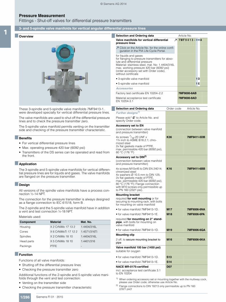
These 3-spindle and 5-spindle valve manifolds 7MF9413-1.. were developed specially for vertical differential pressure lines.
The valve manifolds are used to shut off the differential pressure lines and to check the pressure transmitter zero.
The 5-spindle valve manifold permits venting on the transmitter side and checking of the pressure transmitter characteristic.
■ Benefits
• For vertical differential pressure lines• Max. operating pressure 420 bar (6092 psi)• Transmitters of the DS series can be operated and read from
the front.
■ Application
The 3-spindle and 5-spindle valve manifolds for vertical differen-tial pressure lines are for liquids and gases. The valve manifolds are flanged on the pressure transmitter.
■ Design
All versions of the spindle valve manifolds have a process con-nection ½-14 NPT.
The connection for the pressure transmitter is always designed as a flange connection to IEC 61518, form B .
The 2-spindle and the 5-spindle valve manifold have in addition a vent and test connection ¼-18 NPT.
Materials used:
■ Function
Functions of all valve manifolds:• Shutting off the differential pressure lines• Checking the pressure transmitter zero
Additional functions of the 2-spindle and 5-spindle valve mani-folds through the vent and test connection:• Venting on the transmitter side• Checking the pressure transmitter characteristic
Component Material Mat. No.
Housing X 2 CrNiMo 17 13 2 1.4404/316L
Cones X 6 CrNiMoTi 17 12 2 1.4571/316Ti
Spindles X 2 CrNiMo 18 10 1.4404/316L
Head parts X 5 CrNiMo 18 10 1.4401/316
Packings PTFE -
Selection and Ordering data Article No.Valve manifolds for vertical differential pressure lines
7 M F 9 4 1 3 - 77A
Click on the Article No. for the online confi-guration in the PIA Life Cycle Portal.
for liquids and gasesfor flanging to pressure transmitters for abso-lute and differential pressureMaterial: stainless steel, mat. No: 1.4404/316Lmax. working pressure 420 bar (6092 psi) (order accessory set with Order code),without certificate
• 3-spindle valve manifold 1 D
• 5-spindle valve manifold 1 E
Accessories
Factory test certificate EN 10204–2.2 7MF9000-8AB
Material acceptance test certificate EN 10204-3.1
7MF9000-8AD
Selection and Ordering data Order code Article No.Further designs1)
1) When ordering accessory set or mounting together with the multiway cock, please use Order code; otherwise use Article No.
Please add "-Z" to Article No. and specify Order code.
Accessory set to EN(connection between valve manifold and pressure transmitter)
4x screws 7/16-20 UNF x 1¾ inch to ASME B18.2.1; chro-mized steel2x flat gaskets made of PTFE, max. permissible 420 bar (6092 psi), 80 °C (176 °F)
K36 7MF9411-5DB
Accessory set to DIN2)
2) Flange connections to DIN 19213 only permissible up to PN 160 (2321 psi)!
(connection between valve manifold and pressure transmitter)
4x screws M10x45 to DIN EN 24014; chromized steel4x washers Ø 10.5 mm to DIN 125;2x flat gaskets made of PTFE, max. permissible 420 bar (6092 psi), 80 °C (176 °F); Flange connection with M10 screws only permissible up to PN 160 (2321 psi).
K16 7MF9411-6BB
Mounting bracketrequired for wall mounting or for securing to mounting rack, with bolts for mounting on valve manifold
• for valve manifold 7MF9413-1D. M17 7MF9006-6NA
• for valve manifold 7MF9413-1E. M18 7MF9006-6PA
required for mounting on 2" stand-pipe, with bolts for mounting on valve manifold
• for valve manifold 7MF9413-1D. M19 7MF9006-6QA
Mounting clip
2 off, to secure mounting bracket to pipe
M16 7MF9006-6KA
Valve manifold 100 bar (1450 psi)suitable for oxygen
• for valve manifold 7MF9413-1D. S13
• for valve manifold 7MF9413-1E. S14
NACE MR-0175-certified D07incl. acceptance test certificate 3.1 to EN 10204
FI01_2015_en_kap01.book Seite 286 Mittwoch, 8. Oktober 2014 10:12 10
Pressure MeasurementFitttings - Shut-off valves for differential pressure transmitters
Low-pressure multiway cock1
■ Overview
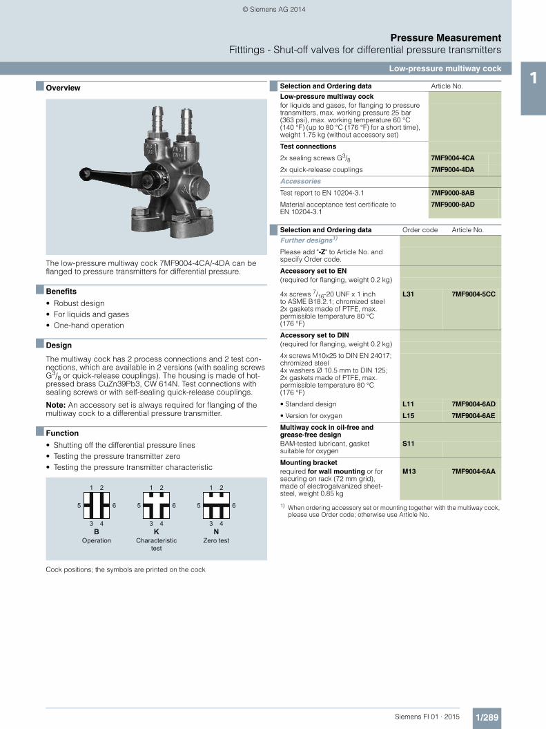
The low-pressure multiway cock 7MF9004-4CA/-4DA can be flanged to pressure transmitters for differential pressure.
■ Benefits
• Robust design• For liquids and gases• One-hand operation
■ Design
The multiway cock has 2 process connections and 2 test con-nections, which are available in 2 versions (with sealing screws G3/8 or quick-release couplings). The housing is made of hot-pressed brass CuZn39Pb3, CW 614N. Test connections with sealing screws or with self-sealing quick-release couplings.
Note: An accessory set is always required for flanging of the multiway cock to a differential pressure transmitter.
■ Function
• Shutting off the differential pressure lines• Testing the pressure transmitter zero• Testing the pressure transmitter characteristic
Cock positions; the symbols are printed on the cock
Operation Characteristic test
Zero test
1
5
2
3 4
1
5
2
3 4
1
5
2
3 4
6 6 6
B K N
Selection and Ordering data Article No.Low-pressure multiway cockfor liquids and gases, for flanging to pressure transmitters, max. working pressure 25 bar (363 psi), max. working temperature 60 °C (140 °F) (up to 80 °C (176 °F) for a short time), weight 1.75 kg (without accessory set)
Test connections
2x sealing screws G3/8 7MF9004-4CA
2x quick-release couplings 7MF9004-4DA
Accessories
Test report to EN 10204-3.1 7MF9000-8AB
Material acceptance test certificate to EN 10204-3.1
7MF9000-8AD
Selection and Ordering data Order code Article No.Further designs1)
1) When ordering accessory set or mounting together with the multiway cock, please use Order code; otherwise use Article No.
Please add "-Z" to Article No. and specify Order code.
Accessory set to EN(required for flanging, weight 0.2 kg)
4x screws 7/16-20 UNF x 1 inch to ASME B18.2.1; chromized steel2x gaskets made of PTFE, max. permissible temperature 80 °C (176 °F)
L31 7MF9004-5CC
Accessory set to DIN(required for flanging, weight 0.2 kg)
4x screws M10x25 to DIN EN 24017; chromized steel4x washers Ø 10.5 mm to DIN 125;2x gaskets made of PTFE, max. permissible temperature 80 °C (176 °F)
• Standard design L11 7MF9004-6AD
• Version for oxygen L15 7MF9004-6AE
Multiway cock in oil-free and grease-free designBAM-tested lubricant, gasket suitable for oxygen
S11
Mounting bracketrequired for wall mounting or for securing on rack (72 mm grid), made of electrogalvanized sheet-steel, weight 0.85 kg
M13 7MF9004-6AA
FI01_2015_en_kap01.book Seite 289 Mittwoch, 8. Oktober 2014 10:12 10
Pressure MeasurementFitttings - Shut-off valves for differential pressure transmitters
Low-pressure multiway cock1
■ Accessories
Accessory set for low-pressure multiway cock• L31: 4 screws 7/16-20 UNF x 1 inch, 2 flat gaskets• L11: 4 screws M10x25 to DIN EN 24017, 4 washers, 2 flat gas-
kets• L15 (suitable for oxygen): 4 screws M10x25 to DIN EN 24017,
4 washers, 2 flat gaskets
Washers Ø 10.5 to DIN 125
Flat gaskets made of PTFE, max. permissible temperature 80 °C (176 °F)
Multiway cock in oil-free and grease-free design• S11: BAM-tested lubricant, gasket suitable for oxygen
Mounting brackets• M13: Required for wall mounting or for securing on rack
(72 mm grid); made of electrogalvanized sheet-steel
■ Options
Test connections• 2 sealing screws G3/8• 2 quick-release couplings
■ Characteristic curves
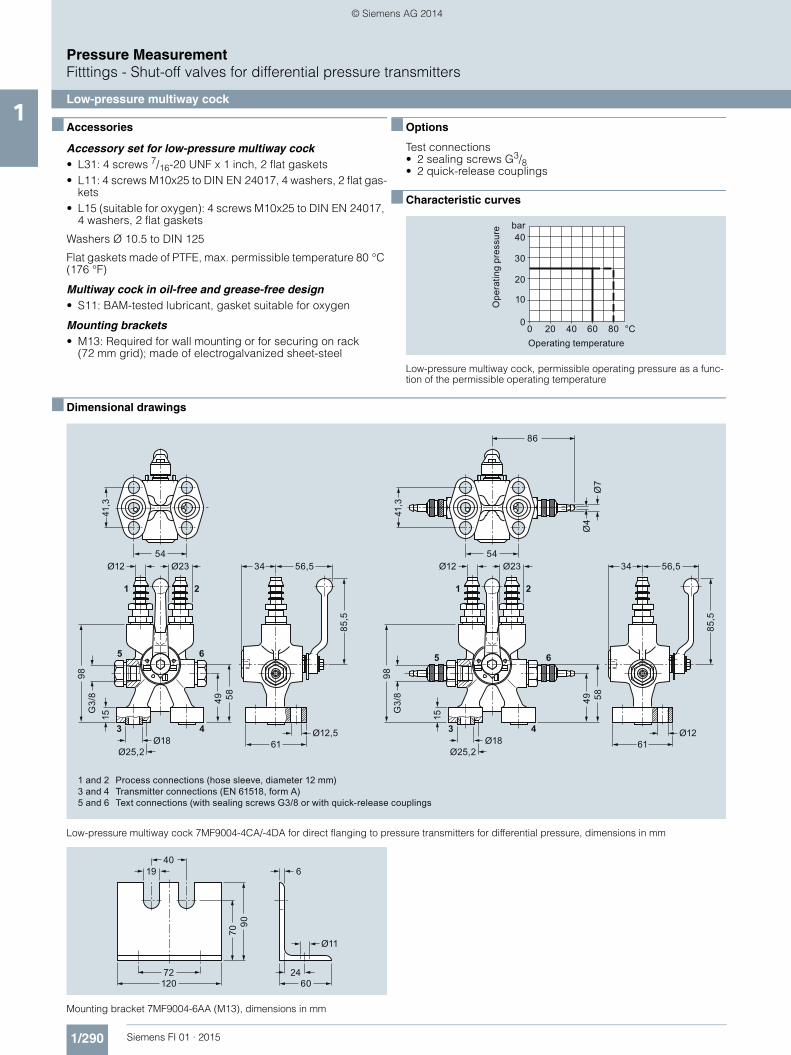
Low-pressure multiway cock, permissible operating pressure as a func-tion of the permissible operating temperature
■ Dimensional drawings
Low-pressure multiway cock 7MF9004-4CA/-4DA for direct flanging to pressure transmitters for differential pressure, dimensions in mm
Mounting bracket 7MF9004-6AA (M13), dimensions in mm
Operating temperature
Ope
ratin
g pr
essu
re bar40
30
20
10
080 °C6040200
1 and 2 Process connections (hose sleeve, diameter 12 mm)3 and 4 Transmitter connections (EN 61518, form A)5 and 6 Text connections (with sealing screws G3/8 or with quick-release couplings
54
1 2
3 4
85,5
61
5 6
86
41,3
49 58
98G
3/8
15
Ø12
Ø7
Ø4
Ø23 56,534
Ø12Ø18
Ø25,2
54
1 2
3 4
85,5
61
5 6
41,3
49 58
98G
3/8
15
Ø12 Ø23 56,534
Ø12,5Ø18
Ø25,2
4019
72120
6
2460
Ø11
9070
FI01_2015_en_kap01.book Seite 290 Mittwoch, 8. Oktober 2014 10:12 10
The oval flange 7MF9408-2C. for pressure transmitters for abso-lute pressure and differential pressure has a ½-14 NPT female thread and is designed for max. operating pressure 400 bar (5800 psi).
■ Accessories
Accessory set for oval flange• E36: 2 screws 7/16-20 UNF x 1½ inch to ASME B18.2.1,
1 flat gasket• E34: 2 screws 7/16-20 UNF x 1½ inch to ASME B18.3,
1 O-ring (FPM 90)• E13: 2 screws M10x40 to DIN EN 4762, 2 washers,
1 O-ring (FPM 90)• E16: 2 screws M10x40 to DIN EN ISO 4762, 2 washers,
1 flat gasket
Washers Ø 10.5 to DIN 125
Flat gaskets made of PTFE, max. 420 bar (6092 psi), 80 °C (176 °F)
O-ring to DIN 3771, 20 x 2.65 – S – FPM90, max. 420 bar (6092 psi), 120 °C (248 °F)
Note: M10 screws only permissible up to PN 160 (2321 psi)!1) When ordering accessory set together with the oval flange, please use
Order code; otherwise use Article No.2) Flange connections with M10 screws only permissible up to PN 160
(2321 psi)
■ Dimensional drawings
Oval flange 7MF9408-2C., dimensions in mm
Selection and Ordering data Article No.Oval flangewith female thread ½-14 NPT, max. working pressure 420 bar (6092 psi), flange connec-tion to IEC 61518, form A
Material
P250GH, mat. No.: 1.0460 7MF9408-2CE
X 2 CrNiMo 17 13 2, mat. No. 1.4404/316L 7MF9408-2CL
Selection and Ordering data Order code Article No.Further designs1)
Please add "-Z" to Article No. and specify Order code.
Accessory set to EN
2x screws 7/16-20 UNF x 1½ inch to ASME B 18.2.3; chro-mized steel1x flat gasket made of PTFE, max. permissible 420 bar (6092 psi), 80 °C (176 °F)
E36 7MF9408-5DA
2x screws 7/16-20 UNF x 1½ inch to ASME B 18.2.3; chro-mized steel1x O-ring to DIN 3771, 20 x 2.65 - S - FPM90, max. permissble 420 bar (6092 psi), 120 °C (248 °F)
E34 7MF9408-5CA
Accessory set to DIN
2x screws M10x40 to DIN EN ISO 4762; chromized steel2x washers Ø 10.5 mm to DIN 125;1x O-ring to DIN 3771, 20 x 2.65 - S - FPM90, max. permissble 420 bar (6092 psi), 120 °C (248 °F)2)
E13 7MF9408-6AA
2x screws M10x40 to DIN EN ISO 4762; chromized steel2x washers Ø 10.5 mm to DIN 125;1x flat gasket made of PTFE, max. permissible 420 bar (6092 psi), 80 °C (176 °F)2)
E16 7MF9408-6BA
NACE MR-0175-certified D07incl. acceptance test certificate 3.1 to EN 10204
Ø12
½-14 NPT
41,3±0,2
Ø11,8
28 31,6
-0,2
FI01_2015_en_kap01.book Seite 291 Mittwoch, 8. Oktober 2014 10:12 10
Adapters enable e.g. a transition from medium connections with NPT thread to shut-off valves to DIN 16270 ... 16272 or pipes in conjunction with a connection gland (e.g. 7MF9008).
■ Design
The connection pieces are made of X 6 CrNiMoTi 17 12 2, mat. No. 1.4571 and available in 3 versions• Thread ¼-18 NPT and connection shank G½ to DIN EN 837-1• Thread ½-14 NPT and connection shank G½ to DIN EN 837-1• Thread ½-14 NPT and thread ½-14 NPT
■ Dimensional drawings
Connection piece with thread ¼-18 NPT and connection shank G½ (7MF9001-1AA), dimensions in mm
Connection piece with thread ½-14 NPT and connection shank G½ (7MF9001-1CA), dimensions in mm
Connection piece with thread ½-14 NPT and thread ½-14 NPT (7MF9001-1DA), dimensions in mm
Connection piece with thread ½-14 NPT and connection shank M20 x 1.5 (7MF9001-1EA), dimensions in mm
Connection piece with pipe union with ferrule 12 S, 12 mm and thread ½-14 NPT (7MF9008-1CA and -1CB), dimensions in mm
Connection piece with pipe union with ferrule 14 S, 14 mm and thread ½-14 NPT (7MF9008-1CC and -1CD), dimensions in mm
Selection and Ordering data Article No.Adapter(weight 0.2 kg)
with thread ¼-18 NPT – G½ 7MF9001-1AA
with thread ½-14 NPT – G½ 7MF9001-1CA
with thread ½-14 NPT – ½-14 NPT 7MF9001-1DA
with thread ½-14 NPT – M20 x 1.5 7MF9001-1EA
with pipe union with ferrule 12 S, 12 mm – ½-14 NPT
• 9 SMnPb 28, mat. No. 1.0718 7MF9008-1CA
• X 6 CrNiMoTi 17 122, mat. No. 1.4571 7MF9008-1CB
with pipe union with ferrule 14 S, 14 mm – ½-14 NPT
• 9 SMnPb 28, mat. No. 1.0718 7MF9008-1CC
• X 6 CrNiMoTi 17 122, mat. No. 1.4571 7MF9008-1CD
SW 22
G½
¼-1
8 N
PT
48
Ø3,
5
1520
SW 22
G½
½-1
4 N
PT
55
Ø3,
5
2013,6
20
SW 22
½-1
4 N
PT
½-1
4 N
PT
50
Ø3,
5
2013,6
2013,6
SW 22
M20
x 1
,5
½-1
4 N
PT
55
Ø3,
5
2013,6
20
SW 24SW 22
½-1
4 N
PT
19,834,5
51
Ø12
SW 27SW 24
19,836
54
½-1
4 N
PT
Ø14
FI01_2015_en_kap01.book Seite 292 Mittwoch, 8. Oktober 2014 10:12 10
Connection glands to connect medium or differential pressure lines to collars G½ to DIN EN 837-1• For rated pressures up to PN 630 (9137psi)• For oxygen only up to PN 250 (3626 psi)
■ Dimensional drawings
Connection gland 7MF9008-1G., dimensions in mm
Selection and Ordering data Article No.Connection screwed glandfor pipelines(weight 0.2 kg)
Material Design
11SMn30(mat. No. 1.0715)
Standard 7MF9008-1GA
X 6 CrNiMoTi 17 12 2(mat. No. 1.4571/316Ti)
Standard 7MF9008-1GB
X 6 CrNiMoTi 17 12 2(mat. No. 1.4571/316Ti)
Grease-free 7MF9008-1GC
SW 27
approx. 47
G½
M20
x 1
,5
Ø7
Ø12
7,51418,5
35
FI01_2015_en_kap01.book Seite 293 Mittwoch, 8. Oktober 2014 10:12 10
Connection parts G½ for pressure gauges and shut-off fittings are available in 3 versions:• Nipple connection• Clamping sleeve• Collar connection piece
■ Dimensional drawings
Nipple connection G½ (M56340-A0001 to -A0003), dimensions in mm
Nipple connection M20 x 1.5 (M56340-A0008), dimensions in mm
Clamping sleeve (M56340-A0004/-A0005), dimensions in mm
Collar connection piece (M56340-A0006/-A0007), dimensions in mm
Selection and Ordering data Article No.Adapters G½for pressure gauges and shut-off fittings
Nipple connectionG½ to DIN 16284 (union nut with nipple and gasket); max. working pressure 400 bar (5802 psi); weight 0.1 kg;connection: G½ to DIN EN 837-1;Female thread G½
Material Mat. No.
CuZn39Pb3 CW 614N M56340-A0001
Union nut 9 SMn 28 kNipple:RSt 37-2
1.0715
1.0037
M56340-A0002
Union nut X 8 CrNiS 18 9Nipple:X 6 CrNiMoTi 17 12 2
1.4305
1.4571/316Ti
M56340-A0003
Nipple connectionM20 x 1.5 to DIN 16284 (union nut with nipple and gasket); max. working pressure 400 bar (5802 psi); weight 0.1 kg;connection: M20 x 1.5 to DIN EN 837-1;Female thread M20 x 1.5
Material Mat. No.
Union nut X 8 CrNiS 18 9Nipple:X 6 CrNiMoTi 17 12 2
1.4305
1.4571/316Ti
M56340-A0008
Clamping sleeveG½ to DIN 16283; max. working pressure 400 bar (5802 psi); weight 0.1 kg;Connections: G½ to DIN EN 837-1;Female thread: G½ right-hand G½ left-hand
Material Mat. No.
CuZn39Pb3 CW614N M56340-A0004
9 SMn 28 k 1.0715 M56340-A0005
Collar-adapter
max. working pressure; weight 0.1 kg;Connections: G½ to DIN EN 837-1;Male thread: G½, G½
Material Mat. No.
CuZn39Pb3 CW614N M56340-A0006
9 SMn 28 k 1.0715 M56340-A0007
SW 27 1630
48
Ø7G½
Ø12
SW 27 1630
48
Ø7M20 x 1,5
Ø14
SW 27 15,5
15,5
36SW 22
2050
20
FI01_2015_en_kap01.book Seite 294 Mittwoch, 8. Oktober 2014 10:12 10
Water traps protect pressure gauges and shut-off fittings from heating up (e.g. by steam) by the water column produced by the water trap.
The max. working temperature is 120 °C (248 °F) at 100 bar (1450 psi), 300 °C (572 °F) at 80 bar (1160 psi) or 400 °C (752 °F) at 63 bar (914 psi). If the temperature of the measured medium is higher, a sufficiently long line has to be connected up-stream of the trap to enable heat dissipation.
■ Design
The water traps are available in U shape (type B) or circular shape (type D) to DIN 16282. They have a weld-on end Ø 20 mm 2.6 mm on the measurement side. The connection on the device side is a clamping sleeve G½ to DIN 16283.
The water traps are made of steel (P250GH) or stainless steel (X 6 CrNiMoTi 17 12 2)
Water traps are designed as standard for max. operating tem-perature 120 °C (248 °F) at max. operating pressure 100 bar (1450 psi) (300 °C (572 °F) at 80 bar (1160 psi), 400 °C (752 °F) at 63 bar (914 psi). Water traps for higher operating pressures and temperatures are available on request.
■ Dimensional drawings
Water traps, type B, M56340-A0043/-A0061, dimensions in mm
Water traps, type D, M56340-A0045/-A0063, dimensions in mm
■ Overview
The sealing rings to EN 837-1 are required to seal measuring in-struments for pressure with the process connection G½B.
■ Dimensional drawings
Sealing ring 7MF9007-7A. to EN 837-1, dimensions in mm
Selection and Ordering data Article No.Water trapsfor pressure gauges and pressure transmit-ters, max. working temperature 120 °C (248 °F), max. working pressure 100 bar (1450 psi) (or 300 °C (572 °F) at 80 bar (1160 psi), or 400 °C (752 °F) at 63 bar (914 psi)), weight 0.7 kg
Water trap B to DIN 16282
Material Mat. No.
P235GH 1.0345 M56340-A0043
X 6 CrNiMoTi 17 12 2 1.4571/316Ti M56340-A0061
Water trap D to DIN 16282
Material Mat. No.
P235GH 1.0345 M56340-A0045
X 6 CrNiMoTi 17 12 2 1.4571/316Ti M56340-A0063
Ø20
145
155
56
200
110
130
56
Selection and Ordering data Article No.Sealing ring to EN 837-1 for thread G½ made of(packing unit 100 pcs)
• Copper 7MF9007-7AA
• Soft iron 7MF9007-7AB
• Stainless steel, mat.-No. 1.4571 7MF9007-7AC
• PTFE 7MF9007-7AD
Accessories
Test report to EN 10204-3.1 7MF9000-8AB
Material acceptance test certificate to EN 10204-3.1
7MF9000-8AD
Ø6,2Ø17,5 2,
0
FI01_2015_en_kap01.book Seite 295 Mittwoch, 8. Oktober 2014 10:12 10
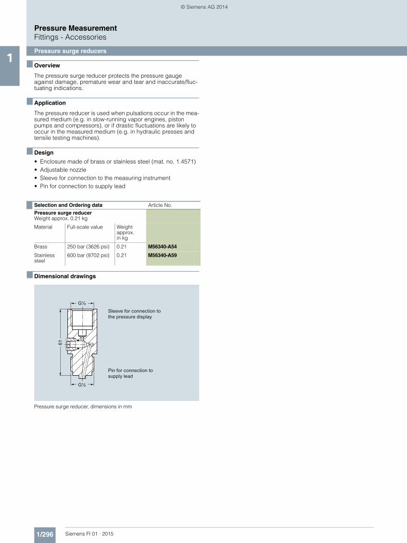
The pressure surge reducer protects the pressure gauge against damage, premature wear and tear and inaccurate/fluc-tuating indications.
■ Application
The pressure reducer is used when pulsations occur in the mea-sured medium (e.g. in slow-running vapor engines, piston pumps and compressors), or if drastic fluctuations are likely to occur in the measured medium (e.g. in hydraulic presses and tensile testing machines).
■ Design
• Enclosure made of brass or stainless steel (mat. no. 1.4571)• Adjustable nozzle• Sleeve for connection to the measuring instrument• Pin for connection to supply lead
■ Dimensional drawings
Pressure surge reducer, dimensions in mm
Selection and Ordering data Article No.Pressure surge reducerWeight approx. 0.21 kg
Material Full-scale value Weight approx.in kg
Brass 250 bar (3626 psi) 0.21 M56340-A54
Stainless steel
600 bar (8702 psi) 0.21 M56340-A59
Pin for connection to supply lead
Sleeve for connection to the pressure display
FI01_2015_en_kap01.book Seite 296 Mittwoch, 8. Oktober 2014 10:12 10
Primary shut-off valves are available in the following versions:• For non-corrosive liquids, gases and vapors• For corrosive liquids and gases• Grease-free for oxygen
The shut-off valves are available in various materials and with various connections (see Selection and Ordering data)
■ Characteristic curves
Shut-off valve 7MF9017-1.., permissible working pressure as a function of the permissible working temperature
Shut-off valve 7MF9017-2.. and -3.., permissible working pressure as a function of the permissible working temperature
■ Dimensional drawings
Shut-off valve 7MF9017–1A., dimensions in mm
Shut-off valve 7MF9017-1B. and -2B., dimensions in mm
Shut-off valves 7MF9017-1C., -1D. and -2C., dimensions in mm
Operating temperature
Ope
ratin
g pr
essu
re bar
Shut-off valve 7MF9017-1..
00
A
400
500
300
200
100
400300200100 500 600 °C
B C D E
Operating temperature
Ope
ratin
g pr
essu
re bar
Shut-off valve 7MF9017-3..
Shut-off valve 7MF9017-2..
00
F
400
500
300
200
100
300200100 400 °C 0 100 200 °C
G H
J
K
Ø80
90
95
G½ Ø11
,2
Ø11
,2
22 22
G½
M20 x 1,5
Ø80
90
95
G½ Ø11
,2
Ø12
22
M20 x 1,5(M22 x 1,5)
Ø80
90
95
Ø12
(Ø14
)
Ø12
(Ø14
)
M20 x 1,5(M22 x 1,5)
FI01_2015_en_kap01.book Seite 297 Mittwoch, 8. Oktober 2014 10:12 10
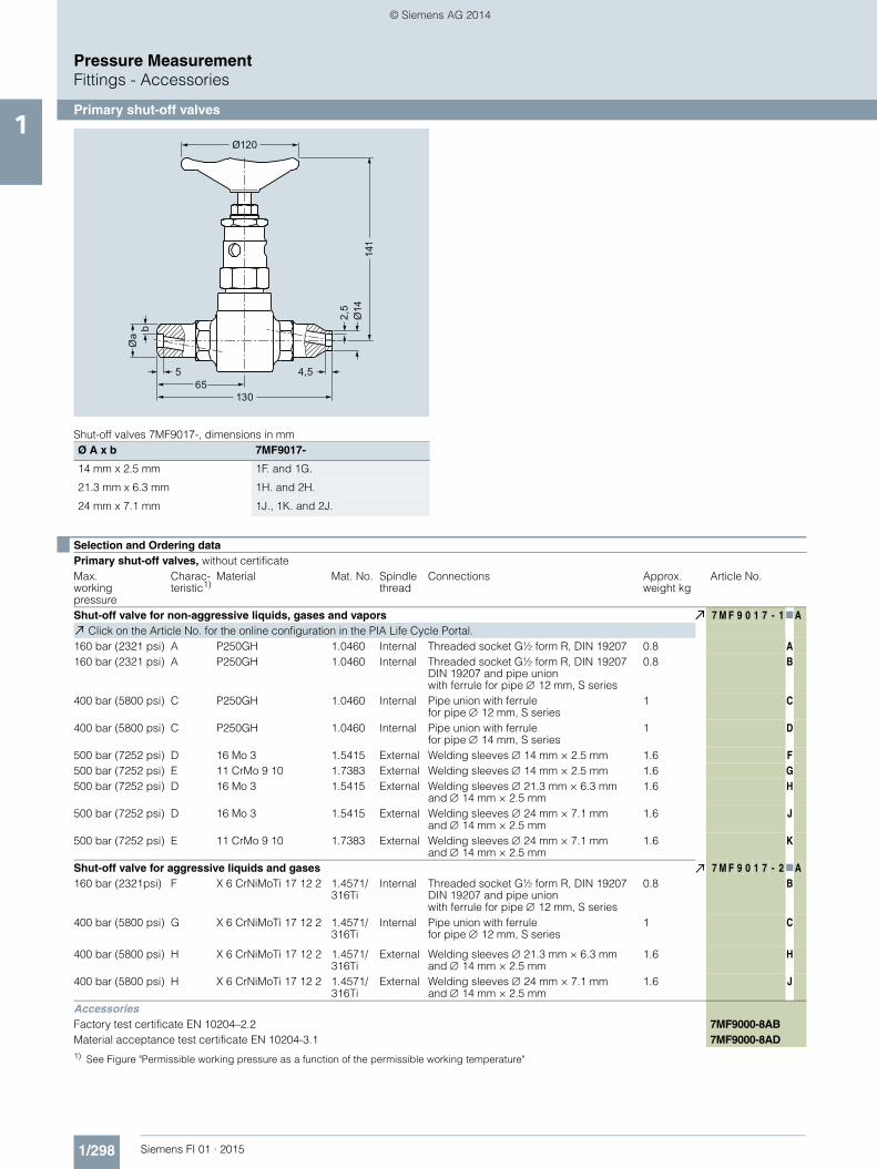
Shut-off valves 7MF9017-, dimensions in mmØ A x b 7MF9017-
14 mm x 2.5 mm 1F. and 1G.
21.3 mm x 6.3 mm 1H. and 2H.
24 mm x 7.1 mm 1J., 1K. and 2J.
Ø120
13065
2,5
Ø14
Øa
b
141
4,55
Selection and Ordering dataPrimary shut-off valves, without certificateMax. working pressure
Charac-teristic1)
Material Mat. No. Spindlethread
Connections Approx. weight kg
Article No.
Shut-off valve for non-aggressive liquids, gases and vapors 7 M F 9 0 1 7 - 1 7AClick on the Article No. for the online configuration in the PIA Life Cycle Portal.
160 bar (2321 psi) A P250GH 1.0460 Internal Threaded socket G½ form R, DIN 19207 0.8 A160 bar (2321 psi) A P250GH 1.0460 Internal Threaded socket G½ form R, DIN 19207
DIN 19207 and pipe unionwith ferrule for pipe 12 mm, S series
0.8 B
400 bar (5800 psi) C P250GH 1.0460 Internal Pipe union with ferrulefor pipe 12 mm, S series
1 C
400 bar (5800 psi) C P250GH 1.0460 Internal Pipe union with ferrulefor pipe 14 mm, S series
1 D
500 bar (7252 psi) D 16 Mo 3 1.5415 External Welding sleeves 14 mm × 2.5 mm 1.6 F500 bar (7252 psi) E 11 CrMo 9 10 1.7383 External Welding sleeves 14 mm × 2.5 mm 1.6 G500 bar (7252 psi) D 16 Mo 3 1.5415 External Welding sleeves 21.3 mm × 6.3 mm
and 14 mm × 2.5 mm1.6 H
500 bar (7252 psi) D 16 Mo 3 1.5415 External Welding sleeves 24 mm × 7.1 mmand 14 mm × 2.5 mm
1.6 J
500 bar (7252 psi) E 11 CrMo 9 10 1.7383 External Welding sleeves 24 mm × 7.1 mmand 14 mm × 2.5 mm
1.6 K
Shut-off valve for aggressive liquids and gases 7 M F 9 0 1 7 - 2 7A160 bar (2321psi) F X 6 CrNiMoTi 17 12 2 1.4571/
316TiInternal Threaded socket G½ form R, DIN 19207
DIN 19207 and pipe unionwith ferrule for pipe 12 mm, S series
0.8 B
400 bar (5800 psi) G X 6 CrNiMoTi 17 12 2 1.4571/316Ti
Internal Pipe union with ferrulefor pipe 12 mm, S series
1 C
400 bar (5800 psi) H X 6 CrNiMoTi 17 12 2 1.4571/316Ti
External Welding sleeves 21.3 mm × 6.3 mmand 14 mm × 2.5 mm
1.6 H
400 bar (5800 psi) H X 6 CrNiMoTi 17 12 2 1.4571/316Ti
External Welding sleeves 24 mm × 7.1 mmand 14 mm × 2.5 mm
1.6 J
AccessoriesFactory test certificate EN 10204–2.2 7MF9000-8ABMaterial acceptance test certificate EN 10204-3.1 7MF9000-8AD1) See Figure "Permissible working pressure as a function of the permissible working temperature"
FI01_2015_en_kap01.book Seite 298 Mittwoch, 8. Oktober 2014 10:12 10
The compensation vessels prevent the level difference which oc-curs with pressure changes in the pressure lines and which fal-sifies the measurement.
According to DIN 19211, the temperature in the compensation vessel must be assumed to be 50 K less than the steam temper-ature in the pipe when calculating the wall thicknesses. This is because the temperature in the compensation vessel during op-eration can only rise up to the saturated steam temperature.
A material acceptance test certificate A to EN 10204-3.1 is avail-able for the materials from which the compensation vessels are made.
■ Characteristic curves
Permissible operating pressure as a function of the permissible operating temperature
■ Dimensional drawings
Compensation vessel 7MF9015-1.., dimensions in mm
Compensation vessel 7MF9015-5.., dimensions in mmOperating temperature
Ope
ratin
g pr
essu
re bar
00
A
400
500
300
200
100
400300200100 500 600 °C
B
C
DE
O Output (see Ordering data for dimensions)I Input (see Ordering data for dimensions)
O
I
100
100
88,9
O Output (see Ordering data for dimensions)I Input (see Ordering data for dimensions)
30 mm longer with 7MF9015-5A.1)
O
I
approx. 11065
351) 58
1)Selection and Ordering dataCompensation vessel, without certificateMax. working pressure
Charac-teristic1)
Material Mat. No. Connections Approx. contentscm³
Approx. weightkg
Article No.Input Output
7 M F 9 0 1 5 - 77AClick on the Article No. for the online configuration in the PIA Life Cycle Portal.
160 bar (2321 psi) A 16 Mo 3 1.5415 Threaded socket G½,form R, DIN 19207
Threaded socket G½,form V, DIN 19207
250 0.8 1 A
250 bar (3626 psi) B 16 Mo 3 1.5415 Welding sleeve21.3 mm × 6.3 mm
Welding sleeve21.3 mm × 6.3 mm
250 0.8 1 B
250 bar (3626 psi) B 16 Mo 3 1.5415 Welding sleeve24 mm × 7.1 mm
Welding sleeve24 mm × 7.1 mm
250 1 1 C
500 bar (7252 psi) E 11 CrMo 9 10 1.7383 Welding sleeve24 mm × 7.1 mm
Welding sleeve24 mm × 7.1 mm
170 1 1 D
250 bar (3626 psi) B 16 Mo 3 1.5415 Welding sleeve33.7 mm × 4.5 mm
Welding sleeve24 mm × 7.1 mm
700 0.7 1 E
160 bar (2321 psi) A 16 Mo 3 1.5415 Threaded socket G½,form R, DIN 19207
Threaded socket G½,form V, DIN 19207
20 1.6 5 A
500 bar (7252 psi) D 16 Mo 3 1.5415 Welding sleeve21.3 mm × 6.3 mm
Welding sleeve21.3 mm × 6.3 mm
20 1.6 5 B
500 bar (7252 psi) D 16 Mo 3 1.5415 Welding sleeve24 mm × 7.1 mm
Welding sleeve24 mm × 7.1 mm
20 1.6 5 C
500 bar (7252 psi) E 11 CrMo 9 10 1.7383 Welding sleeve24 mm × 7.1 mm
Welding sleeve24 mm × 7.1 mm
20 1.6 5 D
AccessoriesFactory test certificate EN 10204–2.2 7MF9000-8ABMaterial acceptance test certificate EN 10204-3.1 7MF9000-8AD1) See Figure "Permissible working pressure as a function of the permissible working temperature"
FI01_2015_en_kap01.book Seite 299 Mittwoch, 8. Oktober 2014 10:12 10
Connection parts are available in the following versions:• Threaded flange pair G½ with stainless steel gasket• Nipple G½ form V to DIN 19207• Union nut G½ made of C 35 to DIN 16284• Gasket B½ (grooved) to DIN 19207
All connection parts are also available grease-free for oxygen.
■ Dimensional drawings
Threaded flange 7MF9007-4CA/-4DA, dimensions in mm
Nipple G½ 7MF9007-4KA/-4LA, dimensions in mm
Union nut G½ 7MF9007-4MA/-4NA, dimensions in mm
Gasket 7MF9007-6BA/-6CA, dimensions in mm
Selection and Ordering data Article No.Threaded flange pair G½
• with stainless steel gasket 7MF9007-4CA
• grease-free for oxygen, with stainless steel gasket
7MF9007-4DA
Scope of delivery:
2x threaded flanges G½ to DIN 19207; material: P250GH (mat. No. 1.0460)
4x hexagon screws M10x45 to DIN EN 24014; Material: C35E (mat. No. 1.1181)
4x hexagon screws M10x50 to DIN EN 24032
1x gasket G½ (7MF9007-6BA) grooved, to DIN 19207; Material: X 6 CrNiMoTi 17 12 2 (mat. No. 14571/316Ti)Only for 7MF9007-4CA!
1x gasket G½ (7MF9k007-6CA), grease-free for oxygen, grooved, to DIN 19207; Material: X 6 CrNiMoTi 17 12 2 (mat. No. 14571/316Ti)Only for 7MF9007-4DA!
Nipple G½
to DIN 19207
• Material: 16 Mo 3 (mat. No. 1.5415) 7MF9007-4KA
• grease-free for oxygen,Material: X 6 CrNiMoTi 17 12 2 (mat. No. 1.4571/316Ti)
7MF9007-4LA
Union nut G½
to DIN 16284
• Material: C35E (mat. No. 1.1181) 7MF9007-4MA
• grease-free for oxygen,Material: X 6 CrNiMoTi 17 12 2 (mat. No. 1.4571/316Ti)