Page 1
Prestressed ConcreteBridge Members
Progress Report 16
ANCHORAGE CHARACTERISTICS OF STRAND
IN PRETENSIONED PRESTRESSED CONCRETE
.. by
r. George Ao Dinsmore! ~
and
Peter Lo Deutsch
•
\Lehigh University
Fritz Laboratory Report 223 0 16
Ju1yl957
Not Released for Publication
Page 2
'.
Thisexperimerutal study has been executed at
LEHIGH UNIVERSITY
FRITZ ENGINEERING LABORATORY
DEPARTMENT OF CIVIL ENGINEERING
Professor Wo Jo EneyDirector and Head
As a part of the investigation sponsored by
PENNSYLVANIA STATE HIGHWAY DEPARTMENT
UNITED STATES BUREAU OF PUBLIC ROADS
CONCRETE PRODUCTS COMPANY OF AMERICA
AMERICAN STEEL AND WIRE DIVISION~
Uo So STEEL CORPORATION
JOHN A ROEBLINGaS SONS~ CORPORATION
REINFORCED CONCRETE RESEARCH COUNCIL
LEHIGH UNIVERSITY
The valued assistance of Dr o Co Eo Ekberg~ Chairman ofthe Structural Concrete Division~ Fritz Laboratory, andthe many members of his staff is a.cknowledged withsincere appreciation o
Page 3
i
•
-~-
INTRODUCTION
This experimental study of anchorage bond in
pretensioned prestressed concrete was undertaken to determine,
in so far as possible, the nature of the phenomenon. The eval-
uation of this information would then permit the formulation
of recommendations for design practice which would prohibit
anchorage bond failures in structural members. Cons~derable
progress has been made toward the fulfillment of these object-
ives, and tentative recommendations are offered at the end of
this report.
Anchorage Bond Failure
The principles involved in anchorage bond failure are
easily seen if a pretensioned member is imagined which has the
strand in its central portion encased in a frictionless tube (See
Fi.gure 1). This beam is, in effect, a post=tensioned member
whose end anchorage is developed by the bond between strand and
concrete over the embedment length L. When the prestress is
released to the member, the prestressing force in the strand
buildsup to its effective level over a short length Lt at the
ends. This is the transfer or transmission length. Should the
required transfer length be greater than the available embedment
length, bond failure must occur at release of prestress., But,
if the embedment length is great enough so that the beam
Page 4
to
•
n.•
~111 ~~ - - ~a .
, < - t::J ,J~ • "' .), L "\0 1 <\ {" a -- rr \. , ~----------_ .....
~_ ...._----~----A Y r- 0. I"l ( - , ", &:J ,....
t
--- r- -1 ~
""\Release of Prestrels
./ "
~/ ' ...V "\
Application of LoadI
I,II:
~.- i ..... ,/' ! "/ ""I
,\
Impending Bond Failure
Figure 1 End Anchor_Ie Concept
Page 5
••
-3-
withstands the transfer of prestress and the beam is subsequently
loaded,increasing the strand force at the unbonded interior of
the beam, the tendency for the strand to slip and screw inward
is likewise increased o If at a given load the embedment length
is not sufficient to develop a total bond force equal to the
strand tension, the strand must slipo
Ultimate Anchorage Length
For any particular beam there must theoretically
exist a certain length of embedment which will provide just
suffi<;:ient anchorage bond to resist the full tensile.capacity
of the strand 0 This embedment is the "ultimate anchorage lengtho"
If the embedment length in the hypothetical beam is made equal
~ to the ultimate anchorage length and the beam is loaded~stretch-
ing the strand to its ultimate strength, the strand will rup-
ture simultaneously with the occurrence of strand slipo
The Slip Limit Envelope
It seems evident that in a member having an available
• embedment less than the ultimate anchorage length, that the
embedment.present provides sufficient bond capacity ~o resist
some particul~r strand tension 0 The bond capacities of
various embedment lengths may then be thought of as defining
a curve, shown in Figure 2 - The S!ip Limit Envelopeo Any
combination of strand tension and embedment length falling
Page 6
Ultimate Anchorage Length
Strand Ultimate
Slip Limit Envelope
Embedment Length
----- ...--.-- - - - - ----"'"
/'/'
//
/
Prestress Level/
LengthTransfer
....I'
l
•
Figure 2 The Slip Limit Envelope
Page 7
1
..
•
-5-
outside the slip limit envelope (that is~ falling in Area 1)
should produce a slip failure. A combination giving a point
within the envelope (Area 2) would be expected to perform
safely.
The determination of the ultimate anchorage length
and the establishment of the slip limit envelope for 7/16 inch
prestressed strands embedded in 6000 psi concrete were the
immediate objectives of the testing program.
DESCRIPTION OF TESTS
The "pull-in" tests reported in this paper simulate
the conditions in the anchorage regions of the hypothetical beam
of Figure 1. They are also believed to faithfully reproduce
the conditions existent in fully bonded members until the
instant of fi.rst slipping. Thirty=four of the pull-in speci
mens were poured and tested in the Fritz Laboratory prestressing
bed in eight series of tests. The specimens were of various
lengths, all 4 11 x 4 11 in cross-section and were reinforced bya
single centrally located 7/16 inch tensioned strand.
Testing Sequence
The testing setup and the sequence of operations is
shown in Figure 3. The prestressing bed is seen to be essentially
a rigid steel frame. Mechanical jacks bearing against the
Page 8
~
- -- -... .~--
-7/16" Strand Tensioned to 18.900 Lbs.
r
•
iI. '
--
-Beam Cast With One End Cast
Against Bulkhead
Strand Burned at Point X,Then Jack Forces Increased
To Ultimate Load.
Figure 3 Diagrams Showing Sequence of Operations
-
Page 9
•
•
-7~
frame push against a moveable beam. The strand is stretched
between the floating beam and the far end of the frame as the
jacks are loaded. The specimen is then poured around the
tensioned strand with one end bearing firmly against the jack
ing end of the frame. After the specimen is cured, the
strand at the free end is burned and the specimen is then equiv
alentto the end portion of a prestressed beam. The pull-in
test is accomplished by additional jacking at the bearing end
which produces increased strand forces simulating tho~arising
from applied moment in a beam. The jacking is continued until
the s~rand slips or ruptures.
The prestressing bed was modified in the course of
the test program by the addition of a second floating beam and
a s~cond set of jacks so that jacking could be performed at
either end of the bed. This permitted the placing of specimens
at both ends of the bed doubling the capacity. Prestress was
released by burning the strand between the specimens and the
testing was then performed at each end independently .
The modification of the bed also made it possible to
release specimens gradually. In this case they were cast at
one end of the bed only. The jacks at the far end were later
unloaded in stages to accomplish the gradual release.
Page 10
"
-8-
,Procedure and Instrumentation
The details of the procedure are best described
with the help of photographs. Figure 4 sh~ws the end of the
prestressing bed with four strands under tension. The strands
are gripped by patented chucks called "Strandvises." These
proved capable of withstanding the ultimate strand tension. In
only one case did a strand break ~n or near the grip and in
that instance the load was well above the guaranteed ultimate '
for the strand. Between the strandvises and the floating beam
are the p~pe dynamometers used in the measurement of strand
tension. They consist of four SR-4 electrical resistance strain
gages mounted on an extra heavy pipe section in such a way as
to be self-compensating for temperature changes.
The specimens are cast in the oiled steel forms after
the strand has been thoroughly cleaned with acetone. At the
bearing end of the specimen the strand passes through a bearing
plate which also serves as the end of the form. In Series IV
through VI 3/8 inch spacers were introduced between the bearing
plate and the frame. When these spacers were removed after
th~ specimen was cured, the bearing plate was firmly clamped
to the frame and a Carbo-Vitrobond cap was poured between the
end of the specimen and the bearing plate to assure positive,-
contact and to compensate for any shrinkage which might have
Page 11
. t
-9-
Figure 4 Tensioning Arrangement
Figure 5 Curing Specimens
Page 12
..
•
...
.:.;,'
-10-
caused the specimen to draw away f~om the bearing surface.
Figure 5 shows ~he specimens in the steel forms being cured
under plastic (note the test cylinders also under plastic
beside the bed). In Figure 6 the caps are shown as poured in
place at the bearing ends of the specimens.
To avoid the superposition of bearing strains on
those resulting from the prestress, an unbonded length is pro-
vided at the bearing ends of the specimens. The lengths of
specimens discussed in thfsreport are the bonded lengths in
all· cases. The bond is effectively destroyed in the unbonded
portion by wrapping the strand with waxed paper smeared with
heavy grease, the resulting hole is cylindrical and no restraint
is imposed on the strand within the length.,
At the release or transfer of prestress, the strand
at the release end is drawn into the specimen by a small amount •
This is called "release slip" as distinguished from "strand
slip," the term describing bond failure. Figure 7 shows mounted
on the strand the dials whi,ch are used to measure release slip
in thosecases where the release is gradual. To obtain accu~-
ate release slip data for sudden release, the set-up shown in
Figure 8 was devised. Here, two dials supported. from the spec-
imen bear against a plate mounted on the strand. This set-up
compensates for any movement of the strand during release and
Page 13
,.
-11-
Figure 6 Bearing End of Specimen
Figure 7 Gradual Release of Prestress
Page 14
..
-12-
,.
Figure 8 SlipGages for SuddenRelease
Figure 9 AluminumChannels for MountingSR-4 Gages
Page 15
-13-
the average of the two dial readings gives a valid measurement
of release slip.
Strain readings were taken along the entire length
of several specimens at the surface of the concrete. Two
different techniques we~e used to obtain these readings. The
SR-4 gages, clearly visible in Figures 6 and 7, are mounted on
the surface of small aluminum channels whose flanges h~ve been
~eformed as shown in Figure 9. The aluminum strips were screwed
to the steel forms before the concrete was poured. The deformed
flanges provided complete bonding with the concrete and the
aluminum offered a smooth dry surface on which the strain
gages could be mounted without fear of moisture contamination.
This technique proved to be entirely practical but mechanical
difficulties in some of the laboratory switching boxes resulted
in the loss of considerable data.
The second procedure for measuring concrete strains
is illustrated in Figure 10. Instead of electrical gages a
mechapical tensometer was used over a gage length of ten
centimeters. Small holes in the probes of the gage slip over
the minute steel spheres set into small aluminum plates which
are, in turn, cemented to the sides of the specimen. .The
technique is slow and laborious but readings can be duplicated
consistently. Corrections must be applied to the data for
Page 16
-14-
Figure 10 Huggenberger Tensometer Measuring Concrete Strains
Figure 11 Slip Gaging at Test
Page 17
-15-
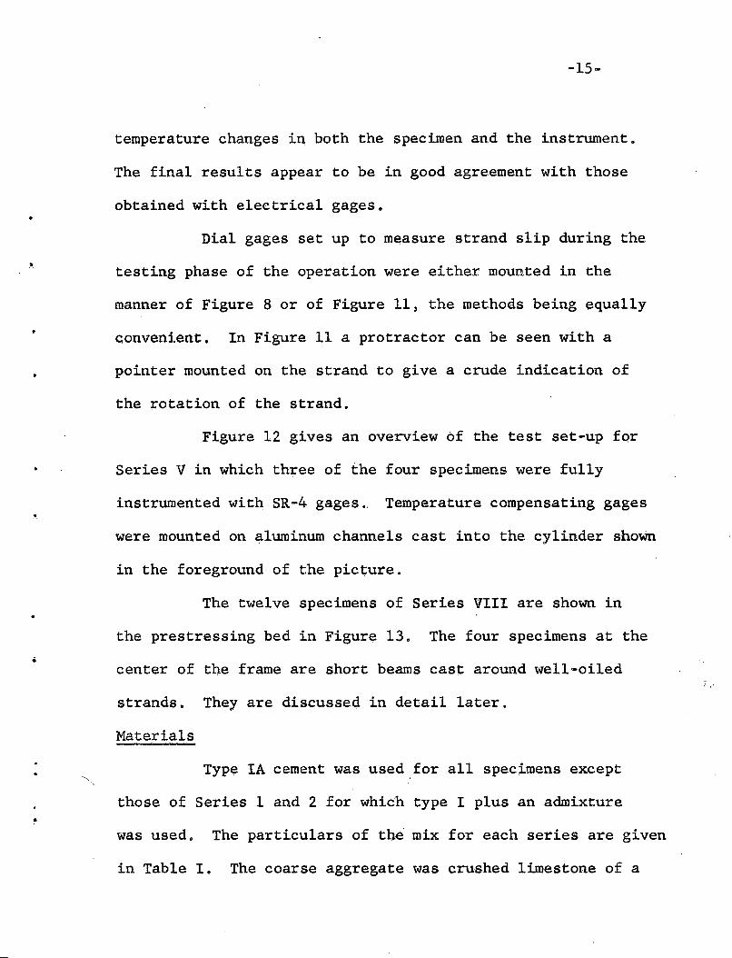
temperature changes in both the specimen and the instrument.
The final results appear to be in good agreement with those
obtained with electrical gages.
Dial gages set up to measure strand slip during the
testing phase of the operation were either mounted in the
manner of Figure 8 or of Figure 11, the methods being equally
convenient. In Figure 11 a protractor can be seen with a
pointer mounted on the strand to give a crude indication of
the rotation of the strand.
Figure 12 gives an overview of the test set-up for
Series V in which three of the four specimens were fully
instrumented wit~ SR-4 gages. Temperature compensating gages
were mounted on aluminum channels cast into the cylinder shoWn
in the foreground of the picture.
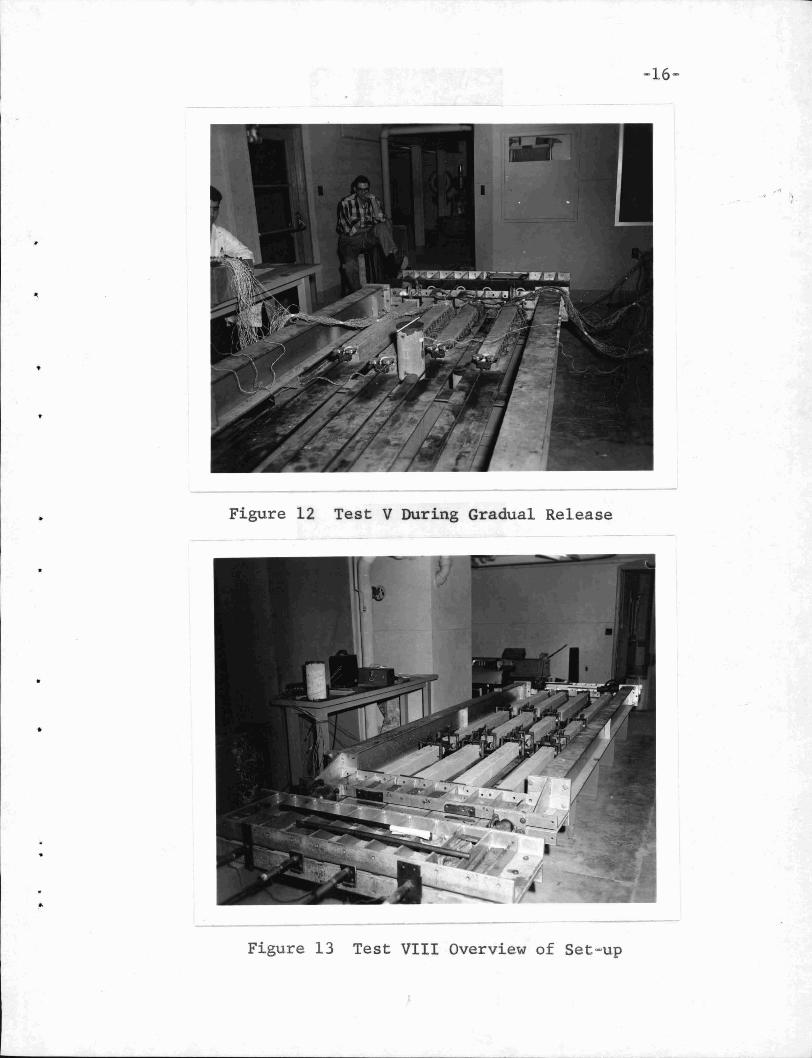
The twelve specimens of Series VIII are shown in
the prestressing bed in Figure 13. The four specimens at the
center of the frame are short beams cast around well-oiled
strands. They are discussed in detail later.
Materials
Type IA cement was used for all specimens except
those of Series 1 and 2 for which type I plus an admixture
was used. The particulars of the mix for each series are given
in Table I. The coarse aggregate was crushed limestone of a
Page 18
•
-16-
Figure 12 Test V During Gradual Release
Figure 13 Test VIII Overview of Set-up
Page 19
•
•
!"
-18~
3/4 inch maximum size. The mixes were designed to yield
a 6000 psi concrete at twenty-eight days. The actual cylinder
strengthsat the time of release, at test~ and at twenty-eight
days are recorded in Table II. In this table values are given
for the modulus of elasticity of the concrete. As indicated,
two methods were used in the determination of these values.
In the flexure procedure one of the regular test specimens
was loaded as a beam, its deflections measured and the tangent
modulus at no load computed from the load-deflection curve.
In those cases where the va1uewas found by cylinder test, the
load-deflection curve was obtained from the data given by
SR-4 gages mounted opposite to one'another at the mid-depth
of the cylinder. Again the tangent modulus is recorded.
The entrained air in all mixes was approximately
three percent.
The strand was 7/16 inch nominal diameter seven-
wire uncoated strand. The manufacturer gives the approximate
area as 0.1089 square inches, the ultimate strength as 27
kips~ the average modulus of elasticity as 27 x 106 psi,and
recommends a design load of 15,120 pounds and a tensioning
load of 18,900 pounds.
In the initial tensioning of strands for the specimens
the 18.9 kip load was approached as nearly as possible. With
four strands involved at a time, all could not be brought
Page 20
-17-
Cement w/cFactor Ratio Mix Quantities in Lb/cu yd
Series Sks/yd Ga1/sk Water Cement Sand Stone
I 7.4 4.6 284 695 1418 1623II 7.3 5.0 300 685 1400 1602III 8.3 400 275 776 1201 1840IV 8.0 4.8 320 755 1170 1790V 8.2 4.2 290 770 1190 1830VI 8 00 5.0 336 755 1125 1790
• VII 8.0 405 300 757 1195 1795VIII 8.0 405 320 750 1160 1780
TABLE I Concrete Mixes
Age in Days Concrete Strength in Psi Tangent Modu-At At At At 1us at Tegt
Series Release Test Release Test 28-Day Psi x 10
I 4 ,-: 7 4600 5250II 6 7 4700 4500III 25 ,26 6500 6500 6500 503 (f)IV 7 7 4250 4250 5600V 19 27 5800 4.8 (f)VI 34 40 6100 6530 6100 503 (c)VII 17 5650 5860 502 (c)VIII 39 39 6000 6150 6000 5.0(f)
600 (c)
TABLE II Concrete Strengths
(f) Ec Determined by Flexure Test.
(c) Ec Determined by Cylinder Test.
Page 21
-19-
exactly to this figure. Certain losses reduced this load to
the effective prestressing forces shown in Tables III and IV.
The values are in the practical range. Losses prior to the
release of prestress include some inelastic deformation of
the frame in the cases where four and five strands were tensioned,
and some relaxation of the strand, an unknown portion of which
was reflected in the dynamometer readings. After release
elastic and creep losses for the unoonded portion and for th~
Carbo-Vitrobond caps are present along with whatev~r losses
develop from the deflection of the end beam of the rigid frame.
RESULTS OF THE TESTS
The requisite data for the determination of the
ultimate anchorage and the establishment of the slip limit
envelope is arranged in order of lengths of the specimens in
Table III and graphical form in Figure 14.
The thirty-four specimens tested ranged in length
from one to twelve feet. No specimen having a bonded l~ngth
of more than four feet slipped either at release of prestress
9r under applied load. Two of the four specimens four feet
long slipped, but none of the six specimens between four and
five feet did. So five to six feet would appear to be a safe
conservative value for the ultimate anchorage length.
Page 22
TABLE III ... Tabulated Results of Pull-In Tests
Page 23
, . . . . .
,~;/l
Bonded Strand' Effective Slip at fl atcSpecimen Length Type Ultimate Strand Prestress ·\.Release Test
NUmber Feet Release Kips Slip Kips In. Psi
1-1 10 Sudden 29,.6 None 18.0 .014 52501-2 12 Sudden 29.8 None 17.9 .033 5250
11-1 6 . Sudden 28.8 None 15.4 .~042 450011-2 8 Sudden 29.5 None 15.8 .028 4500
111-1 5 Sudden 28.3 None 15.2 ND . 6500111-2 7 Sudden 28.4* None 15.1 .047 . 6500
IV-l 1.5 Sudden At Load 16.8 NO 4250IV-2 3.5 Sudden 29.5 None 17.7 ~O 4250IV-3 3 Sudden 29.3 None 17.0 NO 4250IV-4 4.5 Sudden 28.5* None 16.7 NO 4250
IV-5 1 Sudden At Release 10.1 NO 4250IV-6 2 Sudden At Release 14.0 NO 4250IV-7 2.5 Sudden At Load 16~0 NO 4250 ,IV-8 4 Sudden At Load 16.5 NO 4250
V-l 3.5 Gradual At Release 4·7 .403 5800V-2 3 Gradual At Release 4.1 .379 5800V-3 4 Gradual At Release 7.6 .340 5800V-4 3.5 Gradual 27.9 None 17.6 •039 5800
VI-1 4 Gradual 24.6 None 17.5 .021 6530VI-2 3.5 Sudden 27.4* None 16.3 .006 6530VI-3 8 Sudden 26.8* None 16.7 NO 6530VI-4 3.5- Gradual 28.6* None 17.4 .027 6530
~
VII-l 5.5 .. ---. 27.1* None 0 565-0VII-2 4.25 _.. _., 26.4* None 0 5650VII;'3 2.75 At Load ,0 5650VII-4 7 26.5* None 0 5650
J VlII-1 2 Sudden At Load 16.7 .051 6150VIII-2 2.5 Sudden At Load 17.9 .028 6150VIII-3 3 Sudden 30.0 . At Load 17.6 .037 6150VIII-4 3 Sudden 27.4* At Load 17.6 .030 6150
VIII-5 3.5 Sudden 28.8* None 18.2 . ND , 6150VIII-6 3.5 Sudden 26.8* None 17.1 .023 6150VIII-7 4 Sudden 25.6 None 17.2 NO 6150VIII-8 4.5 Sudden 28.2* None 16.9 .028 6150
* Maximum load attained. Strand not broken.
,
TABLE IV - Tabulated Results of 'Pull-In Tests
Page 24
•
-22-
The performance of specimens of four feet and less
in length is seen to be highly erratic and nothing even sug
gesting the theoretical slip limit envelope is indicated.
Two of the specimens shorter than four feet developed the
ultimate strength of the strand. Six such specimens withstood
the release of prestress successfully but failed in slip during
the application of jacking load (The shortest of these was
1 1/2 feet long). Five specimens failed at rel~ase of pre
stress. The one foot ~pecimen and the two foot specimen
were released suddenly. The three) three and one-half) and
four foot specimens slipped during a gradual transfer of pre
stress. For these specimens the transfer length was evidently
in excess of the length o~ the specimen. The performance
of these three specimens is obviously exceptional) but no
satisfactory explanation has yet been discovered.
The performance of the four untensioned speci~ens
is r~markably similar to the performance of those which were
prestressed. The three specim~ns longer than four feet
developed the ultimate strength of the strand, whereas the one
shorter than four feet slipped at a load in exc~ss of the
usual prestress level. It is apparent that the level of
prestress has little if any effect on the bonding capacities.
Page 25
•
•
-23-
No specimen in any of the tests showed any cracking,
spalling or any other indication of distress in the concrete.
Only in Seri~s VIII were any sounds heard from the specimens •
There were sharp reports which accompanied abrupt $lipping
of strand. This unique effect is discussed in detail later.
Many of the specimens tested were later smashed
a~4 the grooves in the concrete surrounding the strands studied.
In all cases in which slip occurred the grooves were highly
.polished, but not in any way destroyed. A polished groove
then indicates that a relative movement between the strand
and the concrete has taken place. All of the specimens which
did not fail in slip showed the same polished appearance in
the transfer region and also at the jacking end. In that
portion of these specimens between the transfer region and
the region affected by the jacking, the grooves showed a dull,
rather chalky appearance. Unfortunately the contrast was not
sufficiently great to permit the measurement of the various
lengths by these observations.
The data presented in Table III is rearranged in
order of series in Table IV to facilitate the following
discussion of each series.
Series I and II
These were preliminary tests designed to establish
the order of magnitude of the ultimate anchorage length. The
Page 26
o
•
-24-
specimens had lengths of six, eight~ ten, and twelve feet
with an additional six inches of unbonded length at the bear
ing end. The strand was quite badly rusted, having been
drawn from old laboratory stock. The release was sudden.
The measurement of release slip was'crude; a single dial was
attached to the strand prior to the burning of .the :strand o
Slips on the order of .01 to .05 inches were observed by this
method.
Series III
The two beams of Series III were five and seven feet
in length with again an additional six inches of unbonded
length at the bearing end. Clean new strand was used for this
and all subsequent tests. The five foot specimen had SR-4
gages mounted on aluminum strips on the sides of the specimen.
Zero readings on these gages were taken just prior to the
sudden release. The strain history of the specimen is recorded
on Figure 15. Immediately after release a strain of 180
micro-inches over the gre~ter length of the specimen was ob
served. Dividing the effective prestress by the area of the
specimen and this strain of 180 micro-inches per inch, the
modulus of elasticity is found to be 503 million, a figure
which checks very nicely with that determined from the load
deflection curve obtained from the specimen under flexural
load.
Page 27
~25=
The transfer length is seen to be on the order of
ten inches for the specimen.
The zero readings prior to the jacking test were
taken twenty=three hours after release. It is seen that creep
resulteq in a fairly uniform increase in strain.
Examination of Figure 15 shows the influence of
the jacking forces penetrating two and one~half feet into the
bonded length of the specimen before the strand finally rup~
tured at a load of 28.3 kips. The same data is shown in
Figure 16 with the pre=test strains taken as a base. The
effect is to smooth the curves and reveal a quite linear
characteristic. The slight increase in strain between the
one and two foot marks ~s probably only further development
of creep under the prestress developed in the transfer length
since the testing required several hours for completion.
The pronounced dip in the strain distribution
curves of Figure 15 at the bearing end suggested the desir~
ability of capping the specimens against their bearing plates
after curing was completed to minimize the losses at release
which undoubtedly accounted for the dip. This dip was not
characteristic of later tests, so the remedy was evidently
appropriate.
After the failure of the strand the specimen was
in reality a prestressed beam, but one having an exceptionally
Page 28
-26-
long transfer length at the jacking end. In Figure 15 it
is seen that, over the entire length disturbed by jacking,
the strand force builds up linearly, suggesting that the
bond is entirely frictional. Considerable residual strain
is noted at the jacking end.
It should be noted that the manipulations at the
jacking end have left completely unaffected the transfer
portion of the original curve. Presumably if the jacking
action had produced strains encroaching on this portion of
the curve, the strand would have slipped. It seems reason
a.ble to conclude, therefore, that the ultimate anchorage
length for this specimen is approximately three and one-half
feet, the sum of the transfer length and the length influ
enced by the jacking. If either of these were increased,
the ultimate anchorage length would be increased. Both of
these lengths will be seen to be variable as the remaining
tests are reviewed.
The second specimen of the series also developed
the full strength of the strand.
Series IV
The eight specimens of Series IV were gradua.ted in
bonded length from one to four and one-half feet in six inch
increments. The specimens were capped in place and an
Page 29
-.
-27-
additiona~ six inches of unbonded length was provided at
the jacking end. Prior to this series the prestressing bed
had been modified by the addition of the second floating
beam which permitted jacking from either end. The release
of the specimens was sudden. No attempt was made to obtain
release slip data since no r~liable procedure had been devised.
Table IV provides an adequate summary of the basic
data. It was in this series that strand slip was first
encountered. The one foot and the two foot specimens slipped
at release but retained an effective prestress of--10.l and 14
kips respectively. The one and one-half foot specimen with
stood the release of prestress showing an effective prestress
of 16.8 kips but began to slip as the jacking load was
increased beyond 18 kips. The two and one-half foot speci
men slipped at a load exceeding 19 kips, and the four foot
specimen at a load in excess of 22-.5 kips. The three foot,
the three and one-half foot, and the four and one-half foot
specimens did not slip.
Dials were affixed to the specimens to measure slip
during the loading by the method of Figure 11. The strands
had been burned off close to the specimen and as the jacking
was continued the button 'on the strand formed by this burning
was drawn into the specimen. Slip is plotted against jacking
Page 30
-28-
Three of the four specimens in this series were
instrumented with SR-4 ga~es over their entire lengths. Their
lengths were three, three and 'one-half and four feet. A
fourth specimen without any special instrumentation was another
at three and one-half feet. This had been indicated as the
ultimate anchorage length in Test III.
Page 31
~29-
The specimens were released gradually. Slip was
measured by the method of Figure 7. The three specimens
carrying the heavy instrumentation all showed abnormal
slipping when only thirty percent of the prestress had been
transferred. All three slipped in excess of 0.3 inches. The
slip is plotted against percent of prestress released for
these specimens in Figure 29. The curve for the fourth spec
imen is compared with those for other "normal" specimens in
Figure 32.
The curves of Figure 29 show that once the slipping
has fully develop.ed it becomes directly proportional to the
prestress released. In Figure 30 the percent of prestress
lost at the load end is plotted with slip and again the three
curves are parallel and straight one slip has developed
throughout the length of the specimens. This seems to estab
lish that the bond has become entirely frictional. Again
it should be noted that in an actual beam the physical
restraints imposed by the concrete place definite limits on
the loss of prestress which can occur. The friction was suf~
ficient for the specimens to develop some effective prestress:
4.1 kips in the three foot, 4.2 kips in the three and one~
half foot, and 7.6 kips in the four foot specimen.
Page 32
. .
-30~
The strain gages along the lengths of the specimens
should have provided an excellent picture of what was happen
ing, but the failure of several contacts in the laboratory
switch boxes resulted in the loss of the zero reference and
the interpretation of the data was made very difficult. The
picture which finally emerged from the confusion is indicated
in Figure 33. Curve 1 represents the release of a small
percent of the prestress, for e~ample 10%. It shows a normal
development of transfer length. The release of additional
prestress exceeds the capacity of the transfer length for
some unknown reason and Curve 2 results. The curve develops
a slope showing a frictional bond at work. A second transfer
length develops in the interior of the specimen, but the
release of additional prestress exceeds its capacity, the
strand slips through the full length of the specimen and the
strains collapse to the level of Curve 3, the bond becoming
entirely frictional.
These three remarkable specimens had shown that
the transfer length could be greater than four feet, suggest
ing an ultimate anchorage length in excess of six feet.
Perhaps even more remarkable was the existence of the fourth
specimen, in every way similar except in instrumentation,
which not on~y declined to slip at release, but when tested
broke the strand at 27.9 kips.
Page 33
-31=
Before the jacking forces were applied~ Huggenberger
tensometer gage points were applied along the length of the
fourth specimen. Under load the curves of Figure 17 were
obtained. They are quite similar to those obtained ·in Series
III except that the influence of the jacking penetrates a
somewhat shorter distance, about a foot and one=half. This
then requires the transfer length to be less than two feet
in this specimen.
The slip vs. load curves developed by the specimens
which slipped and shown in Figure 31 have been previously
discussed.
Series VI
The four specimens of this series were intended to
clarify the unexpected results of Series V, and to reproduce
them if possible. Two fac~ors in particular were to be
checked. It was felt that the gradual release of the pre
stress might have had an effect and secondly there was the
possibility that three of the specimens had been over-vibrated.
When the specimens had been broken open a multitude of pock
marks, almost microscopic, were observed. These had not been
present in other specimens in such numbers. It was felt
that a foam may have collected on the strand as the result
6f over-vibration of the air entrained concrete.
Page 34
•
•
~32-
A four foot specimen and a three and one-half
foot specimen were slated for gradual release. A three and
one-half and an eight foot specimen were to be released
suddenly. The eight foot specimen was to be very severely
over-vibrated. All of the specimens were to have a two foot
unbonded length to permit a full leveling of strains at the
bearing end. They were all to be capped in position and all
were to be adorned with tensometer gage points' over their
entire lengths.
None of the specimens slipped at release.
None of the specimens slipped under test. In each
case the strand attained the guaranteed ultimate load.
The release slip for the specimens gradually re
leased are shown in Figure 32. The build-up of the concrete
strains during the gradual release is shown in Figures 18
and 25. The transfer lengths are a little more than a foot.
The curves are very simi1ar·~to those shown for beams by
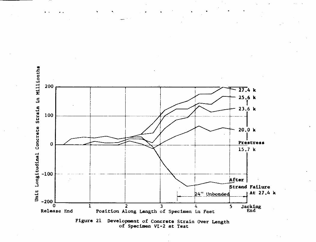
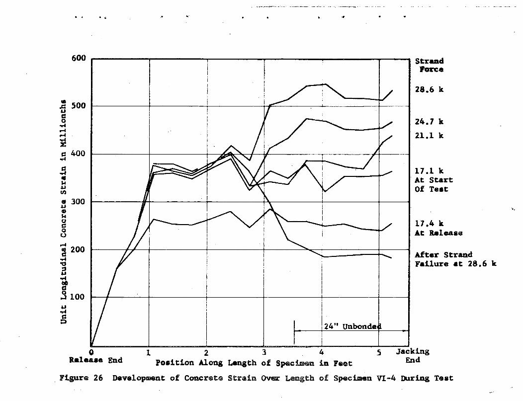
Deb1y in Progress Report 13. Figures 19, 26, and 27 show
the development of the strains under test. A wire in the
strand of the four foot specimen broke (probably at a weld)
at 24.6 kips. Only one set of readings was obtained after
the start of the test. The effect of the jacking was evidently
felt for only a few inches into the bonded length. The curves
Page 35
•
•
-33-
for the three and one-half foot specimen show the effect of
the jacking to be penetrating only about a foot into the
specimen. The curve resulting after strand failure would
show a transfer length of about one foot at the jacking end.
This is quite a contrast to the curve of Series III, but in
each case the curve resulting after strand failure is a good
mirror image of the jacking curve immediately preceeding the
failure.
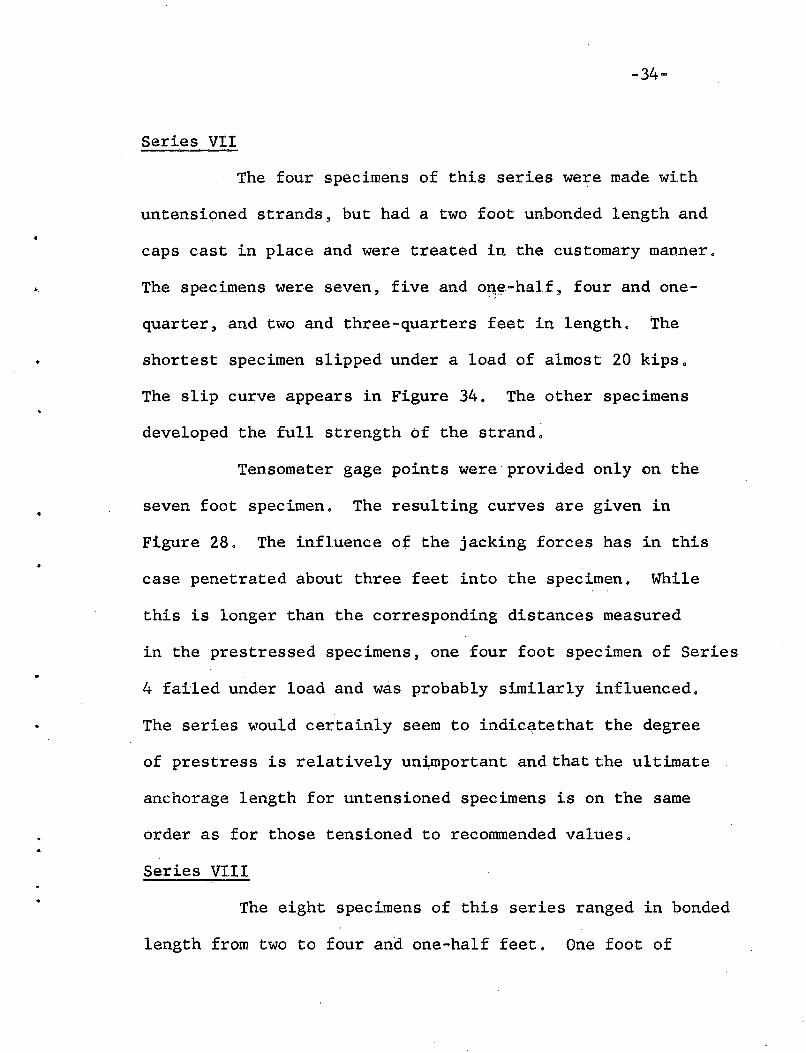
The three and one-half foot specimen which was
suddenly released had a transfer length of about ~en inches.
The influence of the jacking forces penetrated little more
than a foot. The ultimate anchorage length indicated by
this specimen is about two feet. The strains are shown in:J
Figures 20 and 21. The curves continue to rise in an inex-
plicable manner in the unbonded length.
The strain distribution curves for the eight foot
specimen are extremely irregular: Figures 22, 23, and 24.
The data was taken simultaneously with that for the other
specimens and must be accepted as reliable. The influence
of the jacking forces again penetrated only about a foot and
there is no evidence that the over-vibration of the mix had
any adverse effect on the bonding .
Page 36
..
..
-34-
Series VII
The four speci.mens of this series were made with
untensioned strands 3 but had a two foot unbonded length and
caps cast in place and were treated in the customary manner.
The specimens were seven, five and oJ:),~-half3 four and one
quarter, and two and three-quarters feet in length. The
shortest specimen slipped under a load of almost 20 kips.
The slip curve appears in Figure 34. The other specimens
developed the full strength of the strand~
Tensometer gage points were provided only on the
seven foot specimen. The resulting curves are given in
Figure 28. The influence ot the jacking forces has in this
case penetrated about three feet into the specimen. While
this is longer than the corresponding distances measured
in the prestressed specimens, one four foot specimen of Series
4 failed under load and was probably similarly influenced.
The series would certainly seem to indic~tethat the degree
of prestress is relatively uni,.mportant and that the ultimate
anchorage length for untensioned specimens is on the sqrne
order as for those tensioned to recommended values.
Series VIII
The eight specimens of this series ranged in bonded
length from two to four and one-half feet. One foot of
Page 37
•
-35-
unbonded length was provided. The specimens were not capped.
This group of tests was intended primarily to provide addi
tional points for Figure 14 in the critical range of lengths.
The two foot specimen c~rried an effective prestress
of 16.7 kips and slipped under the action of the first small
increment of jacking load. Evidently the transfer length
was almost tvlO feet for this specimen. The two and one-half
fpot specimen managed a load of 23.7 kips before slipping.
The slip curves for "both of these speqimens are given in
Figure 34. They are completely unlike anything seen before.
At the first slip there is a sharp drop in load. The load
then builds up again without any slip and the process is
repeated. Each sudden slip was accompanied by a sharp report.
The jacking was discontinued for two days. No slip occurred
during the rest, but upon resu~ption of jacking the perform
ance was repeated.
The other two specimens at the same end of the
frame were both three feet long. Both indicated a very
slight slip as plotted in Figure 35, but were loaded beyond
the guaranteed strand ultimate. They were then permitted t9
stand under load for two days. At the end of that time both
strands had slipped. Additional jacking broke one of the
strands after some additional slipping and resulted in a slip
curve for the second specimen.
Page 38
..
-36-
In comparing the various slip cu~ves, the slip
magnitudes must be kept in mind. The full scale in Figure
35 is .• 035 inches; in Figure 34, .160 inches; and in Figure
31, .500 inches. Very clearly different phenomena are
represented.
The remaining four specimens developed the full
strength of the strand and showed no slip.
Special Short Beams
Some of the extra space available in the forms
for Series VI and VIII was utilized to pour five short beam
specimens. Two of these were three feet long, one was three
and one-half feet, one was four and one-half f~et, and the
last was five feet long. The beams we+e exactly the same
section as the pull~in specimens. Prior to the pouring of
the beams, the strand was impregnated with oil to destroy
all bond. All of these beams were released suddenly. Slip
data was not successfully obtained.
Figures 36 through 40 show the strain distribution
at the time of release and several days thereafter. It is
evident that so~e readjustment took place during the interval
in several of the specimens siqce the indicated creep is
obviously not proportion~~. ~o the original strains.
Page 39
•
•
=37~
Each of the curves shows a more or less linear
increase in the strain at release to a maxlmum value at the
interior of the beam 0 There is nothing like the customary
transfer length 0 This is evidently a purely frictional
effect which is force.d by the impossibility of the strand
pulling into the interior of the beam == and there is nowhere
for it to goo When the strand is released it attempts to
shorten g which in tu.rn tends to reduce the pitch. The grooves
in the concrete prohibit a significant change in pitch, so
normal· forces are built up along the length of the sp~ral.
This is why strand has such superior bonding qualities in
comparison to plain wireo
The self~locking action observed in these beams
must also be present even in a fully bonded cracked beam
under load. Imagine a crack formed near the end of a beam.
The strand begins to pull into the crack 0 As the strand
slips it has to spiral out of the concrete 0 It is unable
to do this without reversing the twist of the strand around
the crack and destroying·the grooves in the adjacent concrete
or by twisting the uncracked portion of the beam in torsiono
The maximum strains attained in_these specimens
should all be of the same order -~ about two hundred millionths
depending on the values taken for modulus of elasticity and
Page 40
-38-
effective prestress. They a~e actually seen to be: for the
three foot beams 270 and 130; for the three and one-half
foot member, 160; for the four and qne-half foot be~, 145;
and for the five foot specimep, 220.
Page 41
•
-39-
SUMMATION AND CONCLUSIONS
1. The great majority of the tests indicate an ultimate
anchorage length of four feet, but certain exceptions
show that this can be exceeded under some conditions as
yet unknown.
2. The Slip Limit Envelope has been shown to exist in theory
only.
3. The length in which the transfer of prestress is accom
plished is shown to vary inexplicably from ten inches
to a length exceeding four feet in rare instances in spec
imens produced in identical circumstances.
4. The distance into a specimen which is influenced by the
jacking forces may vary from one to perhaps as much as
three feet.
5. No advantage is observed for either sudden or gradual
release.
6. Over-vibration is found to have no effect on bonding.
7. Untensioned or partly tensioned strands require essentially
the same anchorage length as prestressed strands.
8. There is evidently more than one type of slip. One type
progresses smoothly and the load carrying capacity imprbves
as the slip increases. In the second case the slip is
Page 42
-40-
sudden and gives a sharp report. The force builds up
without slipping until another sudden slip occurs. Both
of these mechanisms would be restrained to a limited
activity in a beam o
90 No absolutely foolproof design recommendation can be
made at this stage of the investigation because of the
unexplained exceptions, but it would seem reasonable to
anticipate that any design which prohibits the formation
of a crack at a distance of less than six feet from the
end of a member will be secure against bond failureo
Page 43
..
30I+2
II
2
A roximate
Bonded Length in feet I'8 10
Figure 14 Strand Tension at Failure vs Embedment Length
Page 44
. . .. • .. •
28.3 kI
25.8 k
IStrand
Force1 lI I
1-----------4I------Jt-:---------+-------f-------f---SUdd€f Release I
i!Ii!
II 15.2 k
1--------+--+--------+--- ----"t-----t--------:-----r--------+--:-'At Start
of TestI
i 15.2 k AtI I ReleaseI
I l' ---~~==:-IA\:if~tar Strend
, II Fajilure at 28.3 k
I Ie1----.,6" Unbonded
1i!==~~~==~=-'===~-=-=~-d"""=~=~=-~_ _6_~~~~~=o=l~====::~~=-==-="Release 1 2 3 4 Jacking
End -!. v. -f,' '. .. .-." '.::.ngth ""f _-::'pL"" "m.",,,-''''11 i..... ¥,O,,""t End~OSkC1on hLOUS ~ .• v _ ~_~ __.a u _~=
500fJ)
.c.u~0
.,..j
.....-I
..-l~:?: 400c::
•.-1
c::-.-ltU II-l
~ 300 IQ).w IQi~
Uc::0
C,) 200..-.l~
c::•.-1"0::i~~
..-!onc 100a;..J
.u•.-1c;
::>
0
Fig:-,~'li:'e 15 Development of Concrete Strain Over Length of Specimen III-l
Page 45
. . .. • .. • •
Strandre Atk
cnded
essk
JackingEnd
5
I StrandI
I ForceI
+-----{-- --,
• I I.......... 28.3 k
I --/V 25.8 k-./
lr V-I ~
I
r--- --' Prestr
~15.2
II
i
~I-- -- ---- -----t---- I I ~ After! I ~ Failu
I 28.3Ii
I6" Unb
o Release 1 2 3 4End Position Along Length of Specimen in Feet
Figure 16 Development of Concrete Strain Over Length of Specimen 111-1
300en
..c:.uc::0
..-lP""4P""4..-l 200:Ec::
..-l
c::..-ltt1H.u 100U)
(J).uQ)
H(J
c::0u 0.-I
c-dc::
..-4'U-='.u
..-l
~-lOO0...J
.u..-lc::::>
-200
Page 46
. . .. •
4Jacking
End
After StrandFailure at 27.9 k
6" Unbonded
""""- ..... .... ......
200StrandForce
27.1 k
10025.4 k
22.6 k
Q)
..c:....,co~
.......
.......~
Xc~
c~
l1S,......,til
Q)....,Q)
g 0 t..~"~--~~~-~-~-$-:.;;-~"'~"'~~:::;~4~~~~-- --------o 'u '
,"
] I '\B -100 1--------+----- --~~----"----"r-,---+---~ I'
~ Io~
....,~
c -200 !-- ~-_--..J....-----.L..------'::,;:) 0 1 2 3
Release Position Along Length of SpecimenEnd In Feet .
Figure 17 Development of Concrete Strain OVer Length of Specimen V-4 During Test
Page 47
. . • ..
6Jacking End
5
2l~" Un onded
23%
1-
7. Relea8et~-100% I
2 3Position Along Length of Specimen in Feet
Figure 18 Development of Concrete Strain Over Lengthof Specimen VI-l During Gradual Release
...-IetlC
100-.4'Q::s~
-.400c:0~
~.... 1§ Release End
to.!:.ug 400 r--------,~-----,..__-----r__-----,..._-----or__----__.
-.4...-I...-I....XC
-.4
C 300-.4C\tH.uenQ).u~ 200 t------+--+-------+-------+--------+~.."._----~----__i()
~ou
Page 48
. . .. ."
17.2 kAt StartOf Test
I
500 Hrr--~---~~--'-----r-------or---------------r------""i
~ StrandII Forcefi I1f- +- -+- +- -+- --j1--__~'---2_11.2 kl
IiI
iI !i :I '
~i '7~--: ----~'/ ~. /~ i
!-------j.- I ,. II !~ !
1r1 : 17.5 ki Ii i J.- I At Release
j if/+ -- I "--.I Iliti . i i Atter Stra.ndI: -r--------1-------=. , · I Failure at 23-tk
ij ,,. H !II ,I. t-lrdoo--__2_f+_1I_u_n-+·lro_r__d_e_'a_l---l~==_J=,=~~ I ~_L ~=L J01234 5 ~
Rqlo.pse E·n...~ f ~ nc~~~ in JacKing Endu_~~__ Position Along Length 0 ~p~ Llli~n Feet
c: 300•.-1d~UfJ1
Figure 19 Development of Concrete Strains Over Lengthof Specimen VI-l During T~st
Page 49
. , .. •
Jacking End
21. k
25.6 kI
23.6 k
StrandForce
__ 20. k
1S.J kAt StartOf Teat
I16.3 k
t e1eaaeAfter StrandFailure at 21.4 k
4" Unbonded
1 2 345position Along Length of Specimen in Feet
Development of Concrete Strain Over Length of Specimen VI-2
300
500
200
400
100
Figure 20
ReleaseEnd 0
Page 50
. . .. '.-- '
------L---I
fter------+-IStrand FailureAt 27.4 k
•.c:udo
...f
;:: 200 .------......,--------r-----...,.-----.....,....----....~..:::::~~...f 27.4 kxd 25.6 k
...f I
~ 100 t---------t-----i t_2~3i6 k~ i ------....- 20.0 k
~ ~~~~ Id I _....L.~__~:::::======::::::;~= Prestresso 0 t- ---=~~ ---t---
U I 15.7 k
I._--_._.~--_ .._---+- --
I I
~
~...f'0::2u
...f -100tlOdo
...J
u...f
:5 -2000~----~1-----~2:------~3-----L:-----.."':5~-J-acking
Release End Position Along Length of Specimen Feet End
Figure 21 Development of Concrete Strain Over Lengthof Specimen VI-2 at Test
Page 51
... .. .. .. 0,
16.7 kAt Release
16.1 kAt Startof Test
oJacking
End
StrandForce26.8 k
II 23.4 k\ I
j'J-
I.-t -_ ..-iIIi,
i
I
.-.t······----li
6Specimen in Feet
5Position Along Length of
21
i
+..
II
.---+--11----+---------+-! I
4.J....:5 0
ReleaseEnd
500
.5 300QJk4.Jen
•....•~ 200c:ou
•..c:4.Jc:.3 400~
~....~
c::....
Figure 22 Development of Concrete Strain Over Length of Specimen VI-3
Page 52
..
I,I
26.8 kStraaclUltimate
dad
\ ,
. ~ ., .
500 ..----....,...-----,_---,---....,.---~--__---~--._.,.--•AuCSo....~
~
.i 400 t-----+--++--+----+-----+----___+_---+-----+~L--___+_---+__--__1c:....c:....•~~ 300 t----1If-----JC---#::..-..---+-~-.L_+~:=.:_:~_+_-_4_----,~---_+_-__\_-+_---+_--__I
•U•~~ \o 200 r---+---1r----+----t----+------l----+----+-----:--+_~--t__--_fAfter~ " " Strand.5 ......J Failure..,a....J100
ollalea.e
End
1 2 345 678Position Along Length of Specimen in Feet
9 10Jacking
EndFigure 23 Change in Concrete Strains at Strand Failure for Specimen VI-3
Page 53
. . ... .. .(
After StrandFailure At
26.8 k9 10
JackingEnd
During Teat
81 2 345 6 7position Along Length of Specimen in Feet
24 Development of Concrete Straina Over Length of Specimen Via)
oRel....
EndFigure
Strand
• Fon:eA 2004.1CS0 26.8 k............
23.4 ki!c:: 100....S•...4.1fI)
• 0., 16.1 k
4.1 Pre.tress•...0
8u....~l=100 r.---+---+-----+-----+----4----f-----+---i--\--------jI------I....'U
B...-'-200
Page 54
.. ... '. .. '.. •
•.&::~
g 400 -----_-----_----_-----,..-----------..............;!
JackingEnd
'%. Released
41%'"'t--- __
1 2 3 4Position Along Length of Specimen in Feet
d.....d 300 1-----.:...--+------+-------+---:-----+----------;
..........uU1
U&I• 200 I----~--+----...:-----:~=--..::!Ilor---A--~____::::::;_=__+----_T!oft_----;kgo(.)
....~:;: 100 J--+.f-I=.------+------+-----=~.L-t___-----+----=~-~__1
B....110
~U....BRelease End
Figure 25 Development of Concrete Strain Over Length of Specimen VI-4During Gradual Release
Page 55
... .' .... ......-_.......... ,.~, ~.'. .... .-,'-"_.".--, "-~-_ ..'-" .... "'.
.. ..
After StrandFailure at 28.6 k
17.4 ItA.t Releaae
17.1 k. At Start
Of Te.t
JackingEnd
5
1 24" Unbond.
1 2 3 4Po.1t1on Along Length of SpecimSQ 1n Faet
ollalea.ae End
600 StraadPare.
28.6 k
• 500.cud
24.7 lit0~~
21.1 k~
'i!d 400~
.5•SotUtn
• 300u•SotQc:oo
~200c:~'U
B~
tIDc::.3 100u....g
. Figure 26 Development of ConcretG Strain Ov&ir Length of Specimen VI-4 During Test
Page 56
.. .- .. •
VI-4During Test
After StrandFailure at28.6 k
.JackingEnd
124" Unbonde
24.7 k
21.1 k
17.1 kPrestress
28.6 k
StrandForce
3Length of Specimen in FeetStrain Over Length of Specimen
012Release End Position Along
Figure 27 Development of Concrete
300
-200
10..c:udo....
...-f
...-f
.... 200Xc::.....5cot: 100tI)
G)4-lG)$ofUd
8 a...-f
~....~
a~ -100do~
u....:5
Page 57
•• • ill' • • .*
1.9 It
JlOOu-----~----------..........--------".-----...---'"I...~ 1.0 k
i! 2,uvt----+-----+----+--------4>--------.,~'----__+_---_+__~.5.9t-100CD t------+-----+----~f__-_.fIIC_--+----I-_+_---~----+__-_a
IIeIu
j O~~~~FT~~T~I'U
a
l-1""'----""----"""-----~----L......---....---~-----A--'o 1 2 3 4 S 6 7yi Posl~lta Alc.l& x.-&da of Spec:l.lllla 1a Feat
Page 58
.. . .. " .. .... ..
100
Spec V-4(3.5' Loq - Slip)
""• Spec: V-3 /80 "•• /"..• .;'... ;'
.= ;'
•• 60•It&I•• ./:: "_-/-11M0 40•..
Lcq)..&I
IuIt• 20...
0.40.30.1 0.2Strand Slip in Inc.a
Fipre 29 Str8Dd Slip va Pr••tre.. ...l....d for serie.V SpeciIMtDa Fai11a.& DuriIa& Gradual blu••
o
Page 59
.. .., to: • 4. • •
V-3
100 r====::;;;:::====r------T------,------,"tJc::bJ
"tJqJ
.3 80 ~--------+------::..-~~~-_+_-------_+__------____t~qJ
~
lD·0
..J
c:: 60 t------------~----------+----""'oo".-o I~ ilDc::G)
: ! I i
ti 40 ~----------+----------.----_+------.---- .------+----.~--=--~----.I
~ IH i
~. I~ 20---------------·---+----------------tqJ . I~ Ic::QJokQ)p..
o 0.1 0.2 0.3Strand Slip in Inches
Figure 30 Strand Slip vs Prestress Lost To StrandSlip During Release of Series V Specimens
0.4
Page 60
30 r----~---__.....----r__---~---_.--
Ie
Long)
--+------+--~.-:::._t_--.-....UE.+-.-::!=JlD)
5 -.-----+---=----~- .-:::.::...::::...t-
25 ~-----*,-,~
• (1.5 t Lo• 20 ---_.~.-
a' .....-------.9
.-.. .......~(2 t
~Spec IV-6 Long)..
~,..15 ....-_.- -----~.__._- ------._--_.-
i II
t i
en Spec IV--51 (1 t Lon.& ---'t»1....-_---- ____ I.. ., --- ,.... ",---
~ ".
t 10
•
o 0.1 0.2 0.3Slip in Inche•
0.4 0.5
•
• Figure 31 Slip of Specimens of SeriesIV and V Under Applied Load
Page 61
.. . .. ",,, • ... •
100
Spec VI~
1"",//.., 80•..••~GJ
CIS
•II 60•lot~••..."'"q.,
400
•til•4J
Iulot• 20Pol
o .005 .010 .015 .020Bal.... Slip in Inche.
.025 .030
'\
J'1aure 32 Prosr•••ion of Ilal...e Slip During Gradual ReI....
Page 62
.. ." '. "" '. .' •
Position on Specimen
2d
or4cd,...a.JCf)
C1J.a.JC1J- 3,..(Jd0
C,)
1
Figure 33 Slip Failure at Release - Series V
Page 63
. , .':' .. • ~) • •
I
" 1\" I \,~
COnt n.toned - 2.75')
• J eking Sus ended for 42 hrs
'\,,'\
'\
..- -+~---#_~-.~-+_---__l-.----::~=...IL~--=--==-==--=~g....:..~.-..-----+----~+----~I Long)~I
'\ 4'\l
201--~£.--__+-----+-----+_---____i----_+_--------H~---+_---___+----_t
11-2 (2. ' Long)
25 r-----..,....---.....,..--""'5iI"'.....c:f:----..,....-----r-----r------r-----..,..-----.
lDl:l.....
:a(
c::....CI 15uko~
'0r:cdt 10en'0e·....~
l:l.Q.-< 5
.18.16.14.12.04.02 .06 .08 .10Strand Slip in Inches
Figure 34 Slip of Specimens VII-3. VIII-l and VIII-2 Under Applied Load
o
Page 64
• l .... • • •
dead for 2 bra
x
•10 '------t+.v_--~II"'Z"""--~~---~r----~:-::---__...,:~--~.015 .020 .025 • 35
Slip In Inche.
•Cooor4~ 25 I--.....J-.----+-~,.......J_--+_---_+----_+__-____::__::_::_;_I____~~-_+_---______+
d Spec !VIII-4....•u~..
'U 20 1----1'----+----.+[----+-------1-----+-----+-----1
; ik '4Jen'U•.... 15 ~----+-----+------+-----_+_- -----+-----~----I....Coo
~
Fl;ur& 35 Slip of Specimens VIII-3 and VIII-4While Under Sustained Hi.gh Load
Page 65
• ">.. • • •
400 _---------_---------~--------____.
300 I------------+------.~-~=-=-=---=-="'-=---_+_---------~
200 i-------_c--.",e:;---......-----
100 ~--~_4_--------+-----------__+----~~,_____---___t
o 1 2Position Along Length of Specimen in Feet
Figure 36 Development of Concrete Strain Over Laaathof Specimen VI-5. BeaB With Oiled Strand
3
Page 66
'" , .~-' • •
","'-....... - .......
"
I111 DaysI
Releaae
1 2 3 4Position Along Length of Specimen in Feet
,"'-",
I \,I \ '
Af~er 2 Day"t----~~-_i__-_..,.~--+_-----+_ .--=---~~~---_I
o
c....c....~ 200~en
Figure 31 Concrete Strain Distribution Over Length of Beam VIII - 9
Page 67
.. 'I~" • •
...c.uc::0
'P4~ 300~
'P4Xc::
'P4
c::....4CIS~
~ 200(I).uQJ~Ud0U
~ 100qSc::
....4"0='.u
....4CIOc::0
...1
.u0'P4
c::::J
Afte~
II
1 2 3 4Position Along Length of Specimen in Feet
Figure 38 Concrete Strain Distribution Over Length of Beam VIII - 10
Page 68
300
-------4-,
III
Ii
---------l----------After Re ease
After 11
123Position Along Length of Specimen in Feet
Figure 39 Concrete Strain Distribution Over Length ofBeam VIII- 11.
•
',,-
•
,
300
After
I
I II II '------------+-----_._- --------- ---------+ ---_. -----_..~-_.._-- ---
After 11,D8ysI
012 3Position Along Length of Specimen in Feet
Figur~ 40 Concrete Strain Distribution Over Lengthof Beam VIII ~ 12.