PREVOST AIR SYSTEM IMPROVEMENTS AND LEAK DETECTION PREVOST AIR SYSTEM IMPROVEMENTS AND LEAK DETECTION PREVOST AIR SYSTEM IMPROVEMENTS AND LEAK DETECTION PREVOST AIR SYSTEM IMPROVEMENTS AND LEAK DETECTION PROTECTION AGAINST MOISTURE PROTECTION AGAINST MOISTURE PROTECTION AGAINST MOISTURE PROTECTION AGAINST MOISTURE This article is going to be most helpful to owners of Liberty XLII and H3 coaches, but there are a lot of tips and some information that is applicable to all Prevost Coaches. As our coaches age we begin to experience air leaks. This article is not about air leaks in the braking systems, but is about the house and chassis, excluding the suspension. While all of our coaches make use of air for braking and the suspension newer models are making use of air for a large number of purposes, a lot of them we never realize or think about. The house can have air powered pocket doors, bed lift, generator air bags, dump valves, cabinet slide, rear camera door, floor slide, and other devices. The chassis will have even more air powered systems or devices including the suspension control solenoids, driver seat, tax axle lift, the air gauge on the dash, the OTR system valves, forward shutters, door lock, belt tensioners, retarder control, and on EGR coaches emissions equipment. Further the chassis has slide room controls and seals, as well as a suspension control system that is used to maintain the driving height, or for leveling in a campground. The point is once we start losing air pressure we have to start finding out why, and what has to be done to stop the loss. We can stumble our way around the coach checking the hundreds of fittings or devices or valves, or we can systematically isolate each system to determine if it leaks, and at what rate. By being able to have a means to identify where the leaks are, we or the technicians who service the coach are going to be much more focused and more efficient at stopping them. On older coaches Prevost has not provided a simple means of identifying and isolating individual air lines and systems so owners who want to chase leaks don’t have the best ways to understand where each air line comes from or goes to. The same goes for the house air circuits on some coaches. But it still can be done by trial and error and by accessing the available pneumatic diagrams. The good news is older coaches have less places for potential leaks. Since my coach has reached ten years of age, and with history repeating itself, each of my three coaches at about that age were leaking more than I considered acceptable. So for the third time I am beginning a process to identify and fix whatever is leaking and to minimize the amount of time my auxiliary compressor must run every day. Twice in the past I had gotten my coaches so leak free the compressor would only run once or twice a day. I know from those previous experiences, to get to that point the hours I spend went over 100, maybe even 200. And just so everyone understands not a minute of the time spent was used to repair the brake or
Transcript
PREVOST AIR SYSTEM IMPROVEMENTS AND LEAK DETECTIONPREVOST AIR SYSTEM IMPROVEMENTS AND LEAK DETECTIONPREVOST AIR SYSTEM IMPROVEMENTS AND LEAK DETECTIONPREVOST AIR SYSTEM IMPROVEMENTS AND LEAK DETECTION
PROTECTION AGAINST MOISTUREPROTECTION AGAINST MOISTUREPROTECTION AGAINST MOISTUREPROTECTION AGAINST MOISTURE
This article is going to be most helpful to owners of Liberty XLII and H3 coaches, but
there are a lot of tips and some information that is applicable to all Prevost Coaches.
As our coaches age we begin to experience air leaks. This article is not about air
leaks in the braking systems, but is about the house and chassis, excluding the
suspension. While all of our coaches make use of air for braking and the suspension
newer models are making use of air for a large number of purposes, a lot of them we
never realize or think about.
The house can have air powered pocket doors, bed lift, generator air bags, dump
valves, cabinet slide, rear camera door, floor slide, and other devices. The chassis
will have even more air powered systems or devices including the suspension control
solenoids, driver seat, tax axle lift, the air gauge on the dash, the OTR system valves,
forward shutters, door lock, belt tensioners, retarder control, and on EGR coaches
emissions equipment. Further the chassis has slide room controls and seals, as well
as a suspension control system that is used to maintain the driving height, or for
leveling in a campground. The point is once we start losing air pressure we have to
start finding out why, and what has to be done to stop the loss. We can stumble our
way around the coach checking the hundreds of fittings or devices or valves, or we
can systematically isolate each system to determine if it leaks, and at what rate. By
being able to have a means to identify where the leaks are, we or the technicians
who service the coach are going to be much more focused and more efficient at
stopping them.
On older coaches Prevost has not provided a simple means of identifying and
isolating individual air lines and systems so owners who want to chase leaks don’t
have the best ways to understand where each air line comes from or goes to. The
same goes for the house air circuits on some coaches. But it still can be done by trial
and error and by accessing the available pneumatic diagrams. The good news is
older coaches have less places for potential leaks.
Since my coach has reached ten years of age, and with history repeating itself, each
of my three coaches at about that age were leaking more than I considered
acceptable. So for the third time I am beginning a process to identify and fix whatever
is leaking and to minimize the amount of time my auxiliary compressor must run
every day. Twice in the past I had gotten my coaches so leak free the compressor
would only run once or twice a day. I know from those previous experiences, to get to
that point the hours I spend went over 100, maybe even 200. And just so everyone
understands not a minute of the time spent was used to repair the brake or
suspension systems. Those leaks I repaired on previous coaches were all the
secondary accessory systems and devices not associated with the brakes or the
suspension such as dealing with the leans.
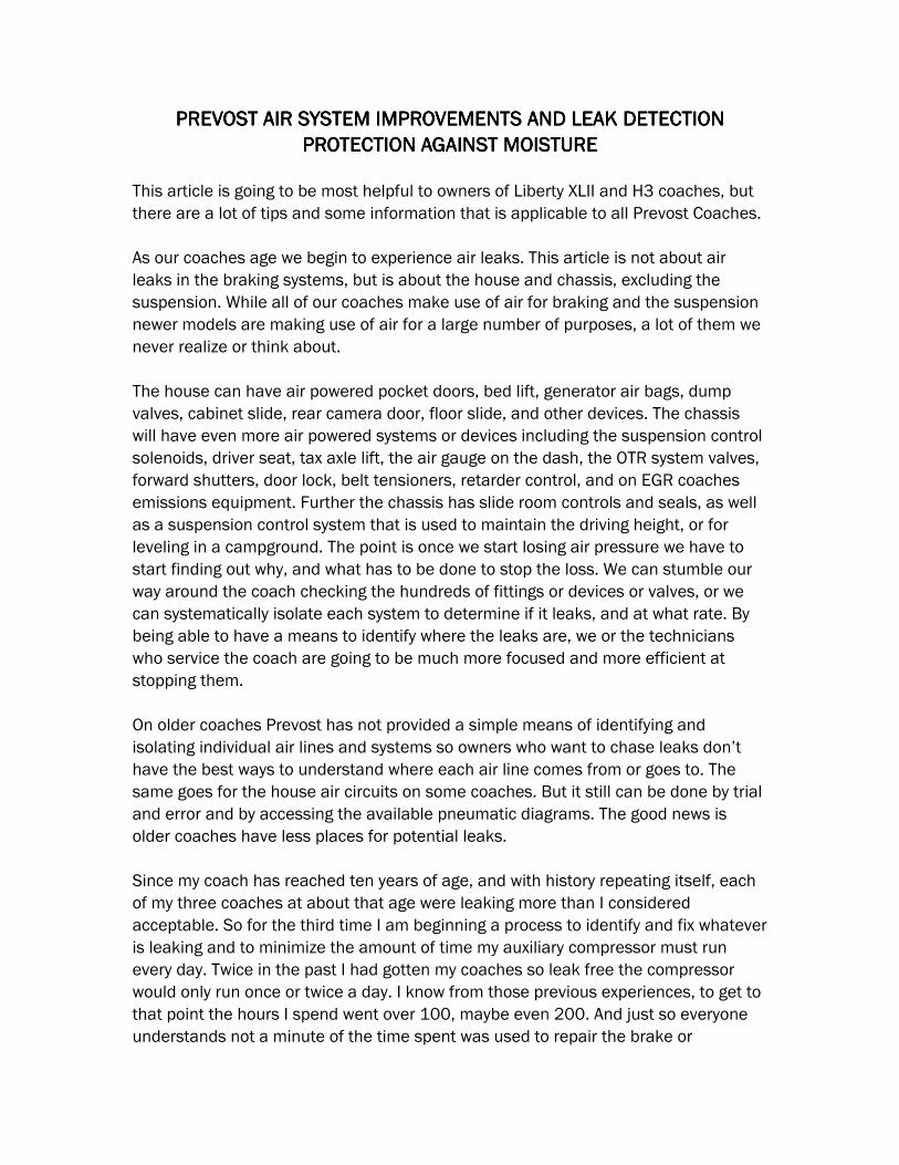
The starting point for me is the most fun part of leak detection. I am creating a
means by which I can identify which system or component is leaking, and in order of
the biggest leaks first, to the smallest leaks I can establish my priorities.
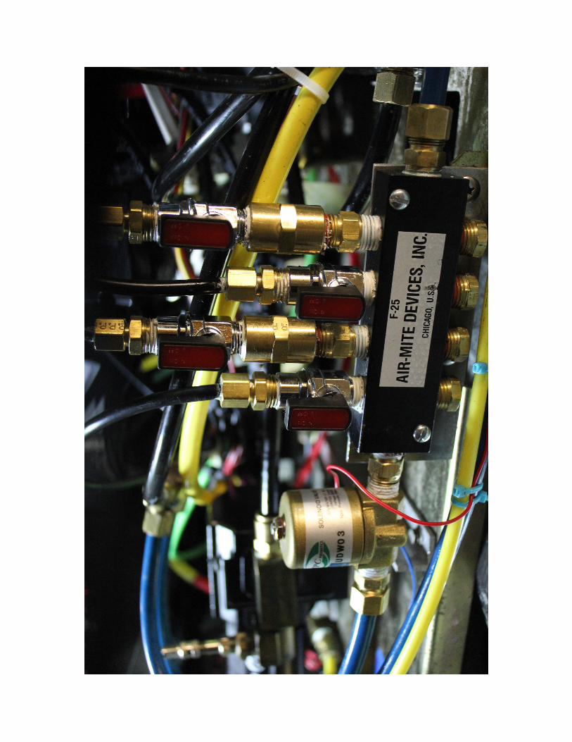
The photo above shows the beginning of the process. I started with the manifold in
the lower center of the photo and that manifold and its mini ball valves with the red
knobs handles all of the house air systems. I did that immediately after learning the
moisture protection for the coach auxiliary compressor was not working, or was not
even existing. Liberty used what we have been calling a spitter, which is a small cup
that traps moisture from the aux compressor, and at the end of the cycle it spits out
the moisture. Conceptually that is a great idea, but in reality most of us don’t know it
is there, or we don’t service it. Over time it stops functioning. Prevost installs a
Norgren water trap seen at the lower RH side of the photo behind the blue hoses. But
we have learned that offers no protection from moisture generated by the aux
compressor.
To appreciate the significance of what happens if you do not prevent moisture from
the aux compressor from entering the coach accessory air tank, consider what
happens when you do collect moisture there. The first thing is the tank becomes the
delivery system for moisture. The accessory tank on almost every coach feeds air to
the house, the suspension, the various coach systems listed above, the slide air
system, and the moisture starts to screw up everything. The internals of the Norgren
spool valves begin to show the white corrosion that aluminum wheels get. Springs
inside valves rust. The moisture, if enough accumulates can create a hydraulic lock in
some components. If you have your coach in a resort for any length of time,
especially in the southeast where the humidity is high and you have to run the aux
compressor to keep the slide seals inflated you can accumulate large amounts of
moisture in an accessory tank in as little as a week unless you have a way to trap it.
So I changed my routing of the aux compressor line to accomplish several things.
That will be discussed later. I did that as part of the project to provide a manifold for
the house air systems.
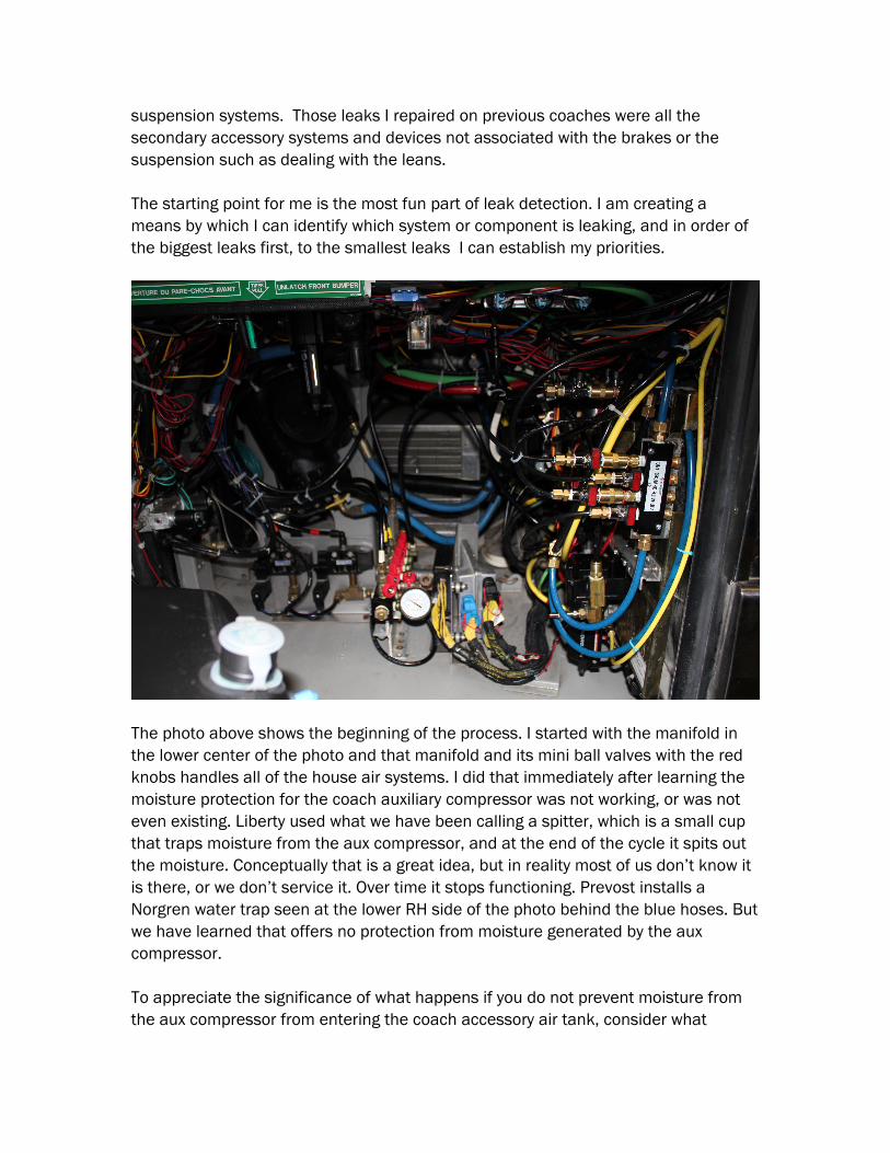
I then replaced the two air manifolds Prevost has installed on XLII coaches. Those
manifolds Prevost provides are nice, but with push in fittings and they have no
provision for adding shut off valves. I built my own manifolds seen at the upper RH
side of the photo above and below so every chassis circuit on those manifolds can be
shut off using the mini ball valves that can be seen with the red handles.
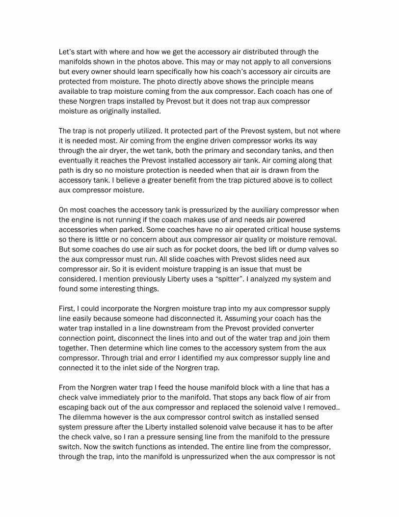
Let’s start with where and how we get the accessory air distributed through the
manifolds shown in the photos above. This may or may not apply to all conversions
but every owner should learn specifically how his coach’s accessory air circuits are
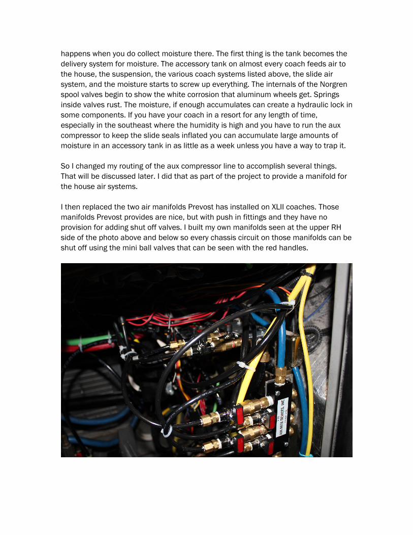
protected from moisture. The photo directly above shows the principle means
available to trap moisture coming from the aux compressor. Each coach has one of
these Norgren traps installed by Prevost but it does not trap aux compressor
moisture as originally installed.
The trap is not properly utilized. It protected part of the Prevost system, but not where
it is needed most. Air coming from the engine driven compressor works its way
through the air dryer, the wet tank, both the primary and secondary tanks, and then
eventually it reaches the Prevost installed accessory air tank. Air coming along that
path is dry so no moisture protection is needed when that air is drawn from the
accessory tank. I believe a greater benefit from the trap pictured above is to collect
aux compressor moisture.
On most coaches the accessory tank is pressurized by the auxiliary compressor when
the engine is not running if the coach makes use of and needs air powered
accessories when parked. Some coaches have no air operated critical house systems
so there is little or no concern about aux compressor air quality or moisture removal.
But some coaches do use air such as for pocket doors, the bed lift or dump valves so
the aux compressor must run. All slide coaches with Prevost slides need aux
compressor air. So it is evident moisture trapping is an issue that must be
considered. I mention previously Liberty uses a “spitter”. I analyzed my system and
found some interesting things.
First, I could incorporate the Norgren moisture trap into my aux compressor supply
line easily because someone had disconnected it. Assuming your coach has the
water trap installed in a line downstream from the Prevost provided converter
connection point, disconnect the lines into and out of the water trap and join them
together. Then determine which line comes to the accessory system from the aux
compressor. Through trial and error I identified my aux compressor supply line and
connected it to the inlet side of the Norgren trap.
From the Norgren water trap I feed the house manifold block with a line that has a
check valve immediately prior to the manifold. That stops any back flow of air from
escaping back out of the aux compressor and replaced the solenoid valve I removed..
The dilemma however is the aux compressor control switch as installed sensed
system pressure after the Liberty installed solenoid valve because it has to be after
the check valve, so I ran a pressure sensing line from the manifold to the pressure
switch. Now the switch functions as intended. The entire line from the compressor,
through the trap, into the manifold is unpressurized when the aux compressor is not
running.. The water trap uses an O ring seal on the cup, and the seal is a notorious
leak point so now with the check valve downstream at the manifold I don’t care if the
cup leaks. In fact I can now drain the cup moisture at any time without losing any
pressure from the accessory air system.
This issue relating to moisture protection for the accessory system is serious and we
have found protection against moisture may not be available at all on some
conversions. The important thing, especially on slide coaches is to determine if
running of the compressor to maintain slide seal pressure is going to allow moisture
to migrate into the Prevost accessory tank. The system described above before I
modified it did not. It should be noted that the Norgren trap is not as effective as the
air dryer our coaches all have as part of the chassis air system so some efforts are
underway to locate a suitable equivalent for the aux compressor.
On Liberty Coaches and I presume many others, accessory air comes from the
Prevost accessory tank and that tank is pressurized when the engine is not running
by the aux compressor. Some coaches, specifically Marathon, but possibly others
have a means of isolating the aux compressor from the Prevost accessory tank by
providing a converter installed accessory air tank that can be either sharing air with
the Prevost tank or not. This has to be known by the coach owner because if the two
tanks are isolated from one another there is no assurance the slide seals if so
equipped will be pressurized when the coach is not running.
In summary I consider my accessory air tank to receive only dry air from either the
engine driven compressor, or my aux compressor. My aux compressor air flow passes
air through the trap, through a check valve and into the manifold. The manifold has a
return line that passes air into the accessory tank, lines to supply the house systems,
a line for the compressor switch to sense system pressure, and a quick connect
fitting for me to use to inflate tires if needed.
By trial and error, and by examining the chassis pneumatic diagrams I have a
reasonable idea where every air line goes on the manifolds I have installed. Since my
objective is to keep aux compressor run time to a minimum, without sacrificing the
ability to get full use of the systems I have determined that the Prevost manifolds do
not need to be pressurized when the coach is parked. The upper, horizontally
mounted manifold is provided by Prevost with a solenoid valve to shut off air to the
manifold unless the key is on. I have added a second solenoid valve to the vertical
manifold (also open with the key on) because the vertical manifold had no systems or
devices needed with the coach was parked.
The valve was placed at the supply end of the manifold block and was wired to the
electrical block provided by Prevost in the electric compartment above it. It has fuse
protection inches from the 24 volt supply.
The installed solenoid valve is shown in the photo below. If it should ever fail to open
I can remove the valve and insert the compression fitting at the supply side of the
valve into the manifold so air continues to be supplied to all the chassis components
whose air supply comes through that valve.
A lot of consideration was given to “what if” scenarios so none of the changes would
cripple the coach without any options to get it going.
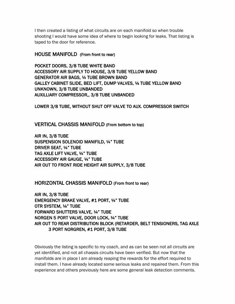
I then created a listing of what circuits are on each manifold so when trouble
shooting I would have some idea of where to begin looking for leaks. That listing is
taped to the door for reference.
HOUSE MANIFOLD HOUSE MANIFOLD HOUSE MANIFOLD HOUSE MANIFOLD (From front to rear)(From front to rear)(From front to rear)(From front to rear)
POCKET DOORS, 3/8 TUPOCKET DOORS, 3/8 TUPOCKET DOORS, 3/8 TUPOCKET DOORS, 3/8 TUBE WHITE BANDBE WHITE BANDBE WHITE BANDBE WHITE BAND
ACCESSORY AIR SUPPLY TO HOUSE, 3/8 TUBE YELLOW BANDACCESSORY AIR SUPPLY TO HOUSE, 3/8 TUBE YELLOW BANDACCESSORY AIR SUPPLY TO HOUSE, 3/8 TUBE YELLOW BANDACCESSORY AIR SUPPLY TO HOUSE, 3/8 TUBE YELLOW BAND
GENERATOR AIR BAGS, ¼ TUBE BROWN BANDGENERATOR AIR BAGS, ¼ TUBE BROWN BANDGENERATOR AIR BAGS, ¼ TUBE BROWN BANDGENERATOR AIR BAGS, ¼ TUBE BROWN BAND
LOWER 3/8 TUBE, WILOWER 3/8 TUBE, WILOWER 3/8 TUBE, WILOWER 3/8 TUBE, WITHOUT SHUT OFF VALVE TO AUX. COMPRESSOR SWITCHTHOUT SHUT OFF VALVE TO AUX. COMPRESSOR SWITCHTHOUT SHUT OFF VALVE TO AUX. COMPRESSOR SWITCHTHOUT SHUT OFF VALVE TO AUX. COMPRESSOR SWITCH
VERTICAL CHASSIS MANIFOLD VERTICAL CHASSIS MANIFOLD VERTICAL CHASSIS MANIFOLD VERTICAL CHASSIS MANIFOLD (From bottom to top)(From bottom to top)(From bottom to top)(From bottom to top)
AIR IN, 3/8 TUBEAIR IN, 3/8 TUBEAIR IN, 3/8 TUBEAIR IN, 3/8 TUBE
ACCESSORY AIR GAUGE, ¼” TUBEACCESSORY AIR GAUGE, ¼” TUBEACCESSORY AIR GAUGE, ¼” TUBEACCESSORY AIR GAUGE, ¼” TUBE
AIR OUT TO FRONT RIDE HEIAIR OUT TO FRONT RIDE HEIAIR OUT TO FRONT RIDE HEIAIR OUT TO FRONT RIDE HEIGHT AIR SUPPLY, 3/8 TUBEGHT AIR SUPPLY, 3/8 TUBEGHT AIR SUPPLY, 3/8 TUBEGHT AIR SUPPLY, 3/8 TUBE
HORIZONTAL CHASSIS MANIFOLD HORIZONTAL CHASSIS MANIFOLD HORIZONTAL CHASSIS MANIFOLD HORIZONTAL CHASSIS MANIFOLD (From front to rear)(From front to rear)(From front to rear)(From front to rear)
AIR IN, 3/8 TUBEAIR IN, 3/8 TUBEAIR IN, 3/8 TUBEAIR IN, 3/8 TUBE
NORGEN 5 PORT VALVE, DOOR LOCK, ¼” TUBENORGEN 5 PORT VALVE, DOOR LOCK, ¼” TUBENORGEN 5 PORT VALVE, DOOR LOCK, ¼” TUBENORGEN 5 PORT VALVE, DOOR LOCK, ¼” TUBE
AIR OUT TO REAR DISTRIBUTION BAIR OUT TO REAR DISTRIBUTION BAIR OUT TO REAR DISTRIBUTION BAIR OUT TO REAR DISTRIBUTION BLOCK (RETARDER, BELT TENSIONERS, TAG AXLE LOCK (RETARDER, BELT TENSIONERS, TAG AXLE LOCK (RETARDER, BELT TENSIONERS, TAG AXLE LOCK (RETARDER, BELT TENSIONERS, TAG AXLE
3 PORT NORGREN, #1 PORT, 3/8 TUBE3 PORT NORGREN, #1 PORT, 3/8 TUBE3 PORT NORGREN, #1 PORT, 3/8 TUBE3 PORT NORGREN, #1 PORT, 3/8 TUBE
Obviously the listing is specific to my coach, and as can be seen not all circuits are
yet identified, and not all chassis circuits have been verified. But now that the
manifolds are in place I am already reaping the rewards for the effort required to
install them. I have already located some serious leaks and repaired them. From this
experience and others previously here are some general leak detection comments.
Past experience has shown one of the most leak prone devices are pressure
regulators. This applies to any used throughout the coach and in my case include the
Prevost installed regulator at the belt tensioners in the rear, as well as the pocket
door pressure regulator on the house circuit.
Valves leak, but do not necessarily exhaust air in a manner in which soapy water and
blowing bubbles makes finding the defective valves practical. An electronic
stethoscope with great sensitivity or an ultrasonic leak detector may have to be used
to sense and “hear” internal leaks. Neither of the two devices are cheap, but they are
an important part of the tools needed to detect leaks. I use this ultrasonic leak
detector but there are others http://www.amprobe.com/amprobe/usen/hvac-
tools/ultrasonic-leak/amp-tmuld-300.htm?pid=73418
The manifolds with shut off valves are the quickest way to isolate the circuits that
have leaks. Pressurize the coach accessory air systems. Then shut off every valve on
every manifold. Go get a drink or snack and in 5 or 10 minutes open the valves on
every manifold one at a time. The valves that will produce the sound of rushing air
when opened are on the circuits in which there is a leak. The biggest leaks will be
evident by the long time it takes for the supply air to stop flowing.
What has not been mentioned are those parts of the air systems that are not run
through a manifold because they do not lend themselves to rerouting. One major
system that falls into that category is the system used in conjunction with slides and
their seals. Slides by their nature are going to have their own complex pneumatic
systems. Seals have to be inflated, and de-inflated. Pins have to be engaged and
disengaged. These are critical functions so leaving them without a manifold or shut
off valves does make leak detection more difficult, but not impossible.
The accessory systems not being run through the manifolds may contribute to the
leaks. To determine where my efforts to fix leaks begins I start by pressurizing the
coach air systems, and then turn off every system that is on a manifold. That tells me
the leak down rate of all other systems.
Then I repressurize the coach and open each manifold and its valves one at a time.
That shows me the new leak down rate and by measuring the time between two
pressure readings (I used 100 PSI to 80 PSI) I could see which manifold made the
fastest leak down rate. Then I pressurized the systems again, and closed each
circuit’s mini ball valve. After a few minutes I opened the mini valves one at a time
and it was evident some had no leaks. But others were heard to have a lot of air
rushing through the valve, and those are the first ones I will inspect for leaks.
I have a long way to go, but I have already isolated and repaired some large leaks. In
the pocket door air line I found leaks at the water trap seal and the pressure
regulator. I eliminated both parts and replaced them with a single pressure regulator.
The water trap has never collected moisture since I added the larger Norgren water
trap to the aux compressor supply line so it was redundant. Just that one single
change has had a large impact on the leak down rate.
I have found another leak associated with a special valve so that valve will be
replaced ASAP. And I am just beginning. There is a lot of work remaining to be done
to find and fix leaks. There is also a lot of work remaining to find and isolate some air
circuits and systems. For example, the house manifold I installed has every circuit
that was once on a Liberty installed manifold. Yet I have been unable to determine
which, if any, has the floor slide on that circuit.
I still do not know where the origin of the air supply lines are for the slide rooms. I
want to at least add a shut off valve to either the complete slide room systems or
each individually to help isolate leaks associated with their systems. There is a valve
now (installed by Prevost) that deflates the slide seals, and there is a means of
retracting and engaging the slide room pins also installed by Prevost so I may already
have the means of trouble shooting for leaks.
The suspension systems (front, LH rear and RH rear) are each a mini system in which
air is locked into their respective air bags by their control valves when the key is off.
Trouble shooting those systems is usually associated with a project to replace air
bags or Norgren valves or both, or when the coach has the tendency to sag down in
front or lean. What may be part of the leak detection process is the air supply but
only as it relates to the origin of the air supply to the Norgren valves and the
associated fittings.
Leaks in the braking system such as might be detected in a pre trip brake inspection
or as a result of brake air gauges showing pressure loss, such as overnight is an
entirely different project.
To find leaks you start at the origin of the system, or from the end of the system. You
work through each valve or fitting in sequence until the leak source is determined.
You may have to use soapy water, your ears, a stethoscope, an ultrasonic leak
detector or you may have to open the system, pressurize it at that point and
determine if it is leaking down. It requires time, patience, stubborn determination, or