Original Instructions Read this guide thoroughly. It contains important safety information. Minimum recommended operator’s age: 16 years old. Keep this Operator’s Guide in the watercraft. 2015 OPERATOR’S Includes Safety, Watercraft and Maintenance Information GUIDE RXP -X 260 TM TM 2 1 9 0 0 1 3 9 6
Transcript
Original Instructions
Read this guide thoroughly.It contains important safety information.Minimum recommended operator’s age: 16 years old.Keep this Operator’s Guide in the watercraft.
2015OPERATOR’S
Includes Safety, Watercraft andMaintenance Information
WARNINGDisregarding any of the safety precautions and instructions contained inthis Operator’s Guide, SAFETY DVD video and on-product safety labelscould cause injury including the possibility of death!
CALIFORNIA PROPOSITION 65 WARNING
WARNINGThis vehicle contains or emits chemicals known to the state of California tocause cancer and birth defects or other reproductive harm.
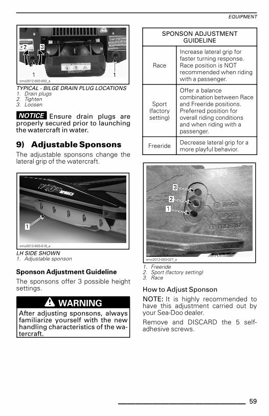
In Canada, products are distributed by Bombardier Recreational Products Inc.(BRP).In USA, products are distributed by BRP US Inc.Knight’s Spray-Nine† is a trademark of Korkay System Ltd.GTX† is a trademark of Castrol Ltd. Used under license.This is a non-exhaustive list of trademarks that are the property of BombardierRecreational Products Inc. or its affiliates:
WARNINGDisregarding any of the safety precautions and instructions contained inthis Operator’s Guide, SAFETY DVD video and on-product safety labelscould cause injury including the possibility of death!
CALIFORNIA PROPOSITION 65 WARNING
WARNINGThis vehicle contains or emits chemicals known to the state of California tocause cancer and birth defects or other reproductive harm.
In Canada, products are distributed by Bombardier Recreational Products Inc.(BRP).In USA, products are distributed by BRP US Inc.Knight’s Spray-Nine† is a trademark of Korkay System Ltd.GTX† is a trademark of Castrol Ltd. Used under license.This is a non-exhaustive list of trademarks that are the property of BombardierRecreational Products Inc. or its affiliates:
DeutschDieses Handbuch ist möglicherweise in Ihrer Landesspracheverfügbar. Bitte wenden Sie sich an Ihren Händler oder besuchen Sie:www.operatorsguide.brp.com.
English This guide may be available in your language. Check with your dealer orgo to: www.operatorsguide.brp.com.
Español Es posible que este manual esté disponible en su idioma. Consulte a sudistribuidor o visite: www.operatorsguide.brp.com.
Français Ce guide peut être disponible dans votre langue. Vérifier avec votreconcessionnaire ou aller à: www.operatorsguide.brp.com.
Nederlands Deze handleiding kan beschikbaar zijn in uw taal. Vraag het aan uw dealerof ga naar: www.operatorsguide.brp.com.
Norsk Denne boken kan finnes tilgjengelig på ditt eget språk. Kontakt dinforhandler eller gå til: www.operatorsguide.brp.com.
Português Este manual pode estar disponível em seu idioma. Fale com suaconcessionária ou visite o site: www.operatorsguide.brp.com.
Suomi Käyttöohjekirja voi olla saatavissa omalla kielelläsi. Tarkista jälleenmyyjältätai käy osoitteessa: www.operatorsguide.brp.com.
Svenska Denna bok kan finnas tillgänglig på ditt språk. Kontakta din återförsäljareeller gå till: www.operatorsguide.brp.com.
Congratulations on your purchaseof a new Sea-Doo® personal water-craft (PWC). It is backed by the BRPwarranty and a network of authorizedSea-Doo personal watercraft dealersready to provide the parts, service oraccessories you may require.Your dealer is committed to your sat-isfaction. He has taken training to per-form the initial setup and inspection ofyour watercraft as well as completedthe final adjustment before you tookpossession. If you need more com-plete servicing information, please askyour dealer.At delivery, you were also informed ofthe warranty coverage and signed thePREDELIVERY CHECK LIST to ensureyour new watercraft was prepared toyour entire satisfaction.
Know Before you GoTo learn how to reduce the risk for youor other persons being injured or killed,read the following sections before youoperate the watercraft:– SAFETY INFORMATION– WATERCRAFT INFORMATION.Read and understand all safety labelson your watercraft and watch atten-tively your SAFETY DVD video.Failure to follow the warnings con-tained in this Operator's Guide canresult in serious injury or death.BRP highly recommends that you takea safe boating course. Please checkwith your dealer or local authorities foravailability in your area.In certain areas, an operator compe-tency card is mandatory to operate apleasure craft.
_______________ 1
FOREWORD
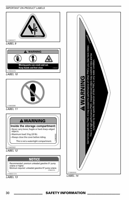
WARNINGGet familiar with this PWC; it mayexceed the performance of otherPWCs you have ridden.
WARNINGThis is a high performance PWC.Inexperienced riders may over-look risks and be surpised by thespecific behavior of this PWC inany water condition.
Safety MessagesThis Operator’s Guide utilizes the fol-lowing symbols and words to empha-size particular information:
The safety alert symbol indicatesa potential injury hazard.
WARNINGIndicates a potential hazard which,if not avoided, could result in seri-ous injury or death.
CAUTION Indicates a poten-tially hazardous situation which, ifnot avoided, could result in minor ormoderate injury.
NOTICE Indicates an instructionwhich, if not followed, could se-verely damage watercraft compo-nents or other property.
About this Operator'sGuideThis Operator's Guide has been pre-pared to acquaint the owner/operatoror passenger with this personal water-craft and its various controls, mainte-nance and safe riding instructions.Keep this Operator's Guide in the wa-tercraft as you can refer to it for oper-ation, instructing others, troubleshoot-ing or maintenance.
Note that this guide is available in sev-eral languages. In the event of any dis-crepancy, the English version shall pre-vail.If you want to view and/or print anextra copy of your Operator's Guide,simply visit the following websitewww.operatorsguide.brp.com.The informations contained in this doc-ument are correct at the time of publi-cation. However, BRP maintains a pol-icy of continuous improvement of itsproducts without imposing upon itselfany obligation to install them on prod-ucts previously manufactured. Dueto late changes, some differences be-tween the manufactured product andthe descriptions and/or specificationsin this guide may occur. BRP reservesthe right at any time to discontinue orchange specifications, designs, fea-tures, models or equipment withoutincurring any obligation upon itself.This Operator's Guide and the SAFETYDVD video should remain with the wa-tercraft when it's sold.
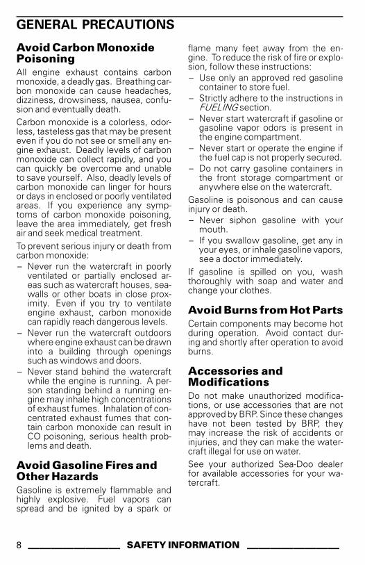
Avoid Carbon MonoxidePoisoningAll engine exhaust contains carbonmonoxide, a deadly gas. Breathing car-bon monoxide can cause headaches,dizziness, drowsiness, nausea, confu-sion and eventually death.Carbon monoxide is a colorless, odor-less, tasteless gas that may be presenteven if you do not see or smell any en-gine exhaust. Deadly levels of carbonmonoxide can collect rapidly, and youcan quickly be overcome and unableto save yourself. Also, deadly levels ofcarbon monoxide can linger for hoursor days in enclosed or poorly ventilatedareas. If you experience any symp-toms of carbon monoxide poisoning,leave the area immediately, get freshair and seek medical treatment.To prevent serious injury or death fromcarbon monoxide:– Never run the watercraft in poorly
ventilated or partially enclosed ar-eas such as watercraft houses, sea-walls or other boats in close prox-imity. Even if you try to ventilateengine exhaust, carbon monoxidecan rapidly reach dangerous levels.
– Never run the watercraft outdoorswhere engine exhaust can be drawninto a building through openingssuch as windows and doors.
– Never stand behind the watercraftwhile the engine is running. A per-son standing behind a running en-gine may inhale high concentrationsof exhaust fumes. Inhalation of con-centrated exhaust fumes that con-tain carbon monoxide can result inCO poisoning, serious health prob-lems and death.
Avoid Gasoline Fires andOther HazardsGasoline is extremely flammable andhighly explosive. Fuel vapors canspread and be ignited by a spark or
flame many feet away from the en-gine. To reduce the risk of fire or explo-sion, follow these instructions:– Use only an approved red gasoline
container to store fuel.– Strictly adhere to the instructions in
FUELING section.– Never start watercraft if gasoline or
gasoline vapor odors is present inthe engine compartment.
– Never start or operate the engine ifthe fuel cap is not properly secured.
– Do not carry gasoline containers inthe front storage compartment oranywhere else on the watercraft.
Gasoline is poisonous and can causeinjury or death.– Never siphon gasoline with your
mouth.– If you swallow gasoline, get any in
your eyes, or inhale gasoline vapors,see a doctor immediately.
If gasoline is spilled on you, washthoroughly with soap and water andchange your clothes.
Avoid Burns from Hot PartsCertain components may become hotduring operation. Avoid contact dur-ing and shortly after operation to avoidburns.
Accessories andModificationsDo not make unauthorized modifica-tions, or use accessories that are notapproved by BRP. Since these changeshave not been tested by BRP, theymay increase the risk of accidents orinjuries, and they can make the water-craft illegal for use on water.See your authorized Sea-Doo dealerfor available accessories for your wa-tercraft.
8 ________ SAFETY INFORMATION ________
SPECIAL SAFETY MESSAGES
Reminders Regarding SafeOperationThe performance of this watercraftmay significantly exceed that of otherwatercraft you may have operated.Make sure you read and understandthe content of this Operator's Guideto become completely familiar withthe controls and operation of the wa-tercraft before embarking on your firsttrip, or taking on a passenger(s). If youhave not had the opportunity to do so,practice driving solo in a suitable traf-fic free area to become accustomedto the feel and response of each con-trol. Be fully familiar with all controlsbefore accelerating above idle speed.Do not assume that all PWCs handleidentically. Each model differs, oftensubstantially.Always keep in mind that as the throt-tle lever is returned to the idle position,less directional control is available. Toturn the watercraft, both steering andthrottle are necessary. Do not releasethrottle when trying to steer away fromobjects. Your need throttle to steer. Ifthe engine is shut off, directional con-trol is lost.Although most watercraft have nomeans of braking, advancement intechnologies now permit us to offermodels that are equipped with a brak-ing system called the iBRTM system.Practice braking maneuvers in a safetraffic-free area to become familiarwith handling under braking and withstopping distances under various oper-ating conditions.
WARNINGStopping distance will vary de-pending on initial speed, load,wind, number of riders and waterconditions. The amount of brakingpower commanded by the opera-tor using the iBR lever (intelligentBrake and Reverse) will also affectstopping distance.
When braking, riders must brace them-selves against the deceleration forceto prevent from moving forward on thewatercraft and losing balance.When operating an iBR equipped wa-tercraft, be aware that other boats fol-lowing or operating in close proximitymay not be able to stop as quickly.When at speed and the brake is firstapplied, a plume of water will shoot upin the air behind the watercraft whichmay cause the operator of a followingwatercraft to momentarily loose sightof your PWC. It is important to informthe operator of a watercraft who in-tends to follow in a convoy formation,of the braking and maneuvering capa-bility of your PWC, what the plume ofwater indicates, and that a greater dis-tance should be maintained betweenwatercraft.When actuating the iBR control leverwhile the watercraft has some for-ward speed, the braking mode willengage and generate a decelerationproportional to the iBR lever position.The more you pull in the iBR lever, thegreater the braking force becomes.Be careful to gradually actuate the iBRlever to adjust the intensity of the brak-ing force, and to simultaneously re-lease the throttle lever.The brake feature of the iBR systemcannot prevent your PWC from drift-ing due to current or wind. It has nobraking effect on the rearward motion.Also note that your engine must berunning to be able to use the brake.The personal watercraft jet thrust cancause injury. The jet pump may pick updebris and throw it rearward causing arisk of injuring people, damaging the jetpump, or other property.Observe the instructions on all safetylabels. They are there to help assurethat you have a safe and enjoyable out-ing.
________ SAFETY INFORMATION ________ 9
SPECIAL SAFETY MESSAGES
Do not store any objects in areas thatare not designed specifically for stor-age.Riding with a passenger makes thePWC handle differently and requiresgreater skill.This PWC comes equipped with frontand rear eyelets for mooring the wa-tercraft or for attachment on a trailer.It cannot be used to attach a tow ropefor a skier, tube or wake boarder. Donot use these attachment points or anyother portion of the watercraft to towa para-sail or any other craft. Personalinjury or severe damage may occur.Certain PWC models come equippedwith tow eyelets which, can be usedto attach a tow rope for a skier, tubeor wake boarder. Do not use these at-tachment points or any other portion ofthe watercraft to tow a para-sail or anyother craft. Personal injury or severedamage may occur.Combustion engines need air to op-erate; consequently this PWC cannotbe totally watertight. Any maneuverssuch as turning constantly in tight cir-cles, plunging the bow through waves,or capsizing the watercraft, that causethe air inlet openings to be under wa-ter may cause severe engine problemsdue to water ingestion. Refer to OP-ERATING INSTRUCTIONS subsectionand the WARRANTY section containedin this Operator's Guide.Engine exhaust contains carbonmonoxide (CO), which can cause seri-ous health problems or death if inhaledin sufficient quantities. Do not operatethe PWC in a confined area or allowCO to accumulate around the PWC,or in enclosed or sheltered areas suchas when docked, or when rafting. Beaware of the risk of CO emanationsfrom exhaust of other PWCs.Know the waters in which the water-craft is to be operated. Current, tides,rapids, hidden obstacles, wakes andwaves etc. can affect safe operation.
It is not advisable to operate the wa-tercraft in rough waters or inclementweather.In shallow water, proceed with cautionand at very low speeds. Grounding orabrupt stops may result in injury andwatercraft damage. Debris may alsobe picked up and thrown rearward bythe jet pump onto people or property.Keep the tether cord attached to theoperator's PFD or wrist (wrist straprequired) at all times and keep it freefrom snagging on the handlebars tohelp ensure the engine stops shouldthe operator fall off. After riding, re-move the tether cord from the enginecut-off switch to avoid unauthorizeduse by children or others. If the op-erator falls off the watercraft and thetether cord is not attached as recom-mended, the watercraft engine will notstop.Ride within your limits and level of rid-ing ability.Always ride responsibly and safely.Use common sense and courtesy.Respect no wake zones, the environ-ment, and the rights of other users ofthe waterways. As the operator andowner of a PWC, you are responsiblefor damage by the wake of your PWC.Do not let anyone throw refuse over-board.While your watercraft has the ca-pacity of operating at high speeds, itis strongly recommended that highspeed operation only be applied whenideal conditions exist and are permit-ted. Higher speed operation requires ahigher degree of skill and increases therisk of severe injuries.The forces generated on the body ofriders while turning, negotiating wavesor wakes, operating in choppy waters,or falling off the watercraft, especiallyat higher speeds, may cause injury in-cluding the possibility of broken bonesor more serious bodily injuries. Re-main flexible and avoid sharp turns.
10 _______ SAFETY INFORMATION ________
SPECIAL SAFETY MESSAGES
PWCs are not designed for night-timeoperation.Avoid riding in very rough waters orpracticing extreme maneuvers likejumping wakes or waves.Everyone participating in a water sportshould observe these guidelines:– Riding with passenger makes the
watercraft handle differently and re-quires greater skill.
– Always respect the safety and com-fort of your passenger.
– Always wear an approved personalflotation device (PFD). Wearinga properly designed PFD helps astunned or unconscious person stayafloat.
– Be considerate to others you sharethe water with.
– Give immediate attention to a per-son who has fallen. He or she isvulnerable in the water alone andmay not be seen by other boaters.
– Approach a person in the water fromthe lee side (opposite the directionof the wind). Turn off the motor be-fore coming close to the person.
– Turn off the engine and anchor thewatercraft before swimming.
– Swim only in areas designated assafe for swimming. These are usu-ally marked with a swim area buoy.Do not swim alone or at night.
�������
SWIM AREA BUOY
– Do not drive the watercraft directlybehind a water skier, tuber or wake-boarder. At 40 km/h (25 MPH) perhour, the watercraft will overtake aperson who falls in the water 60 m(197 ft) in front of your watercraft inabout 5 seconds.
– Shut off the engine and remove thetether cord from the engine cut-offswitch when anyone is in the waternearby.
– Stay at least 45 m (148 ft) awayfrom areas marked by a diver downfloat.
Avoid personal injury! Do not allowanyone near the propulsion system orintake grate, even when the engineis off. Items such as long hair, looseclothing or personal flotation devicestraps can become entangled in mov-ing parts resulting in serious injury ordrowning. In shallow water, shells,sand, pebbles or other objects couldbe drawn up by the jet pump and bethrown rearward.
�������
DIVER DOWN FLOAT
________ SAFETY INFORMATION ________ 11
SPECIAL SAFETY MESSAGES
For more information on approved, le-gal and safe practice of water sports,please contact the local legal authorityon water sports safety for the area youplan to practice in.
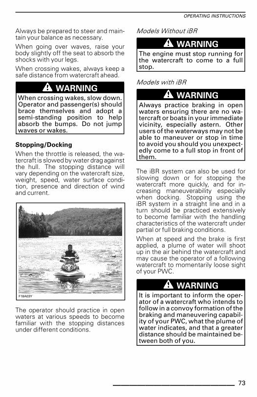
Before Getting Underway
For safety reasons and proper care, al-ways perform the pre-ride inspectionas specified in your Operator's Guidebefore operating your watercraft.Do not exceed the payload or pas-senger capacities for your watercraft.Overloading can affect maneuverabil-ity, stability and performance. Also,heavy seas reduce capacity. A payloador person capacity plate is not an ex-cuse for failure to use common senseor good judgment.Regularly inspect the PWC, hull, en-gine, safety equipment, and all otherboating gear and keep them in safe op-erating condition.Be sure you have at least the minimumrequired safety equipment, PFDs andany additional gear needed for yourcruise.Ensure that all lifesaving equipment,including fire extinguisher, are in safeoperating condition and easily acces-sible. Show all passengers where thisequipment is stored on the PWC, andmake sure they know how to use it.Keep an eye on the weather. Check lo-cal weather broadcasts before depar-ture. Be alert to changing conditions.Keep accurate and up-to-date charts ofthe boating area on board. Before get-ting underway, check water conditionsin the planned boating area.Ensure there is enough fuel on boardfor the planned trip. Always verify fuellevel before use and during the ride.Apply the principle of 1/3 of the fuelto reach your destination, 1/3 to re-turn, and keep 1/3 in reserve. Allowfor changes due to adverse weather orother delays.
Operator and Passenger Awareness
Read and understand all safety labelson the Sea-Doo PWC, the Operator'sGuide, all other safety documents, andwatch the SAFETY DVD video beforeoperating the PWC.Respect applicable laws. Check localand federal boating laws applicableto the waterways where you intendto use your watercraft. Learn the lo-cal navigation rules. Know and under-stand the applicable navigation system(such as buoys and signs).Remember that sun, wind, fatigue orillness may impair your judgement andreaction time.Operation of this PWC by a person un-der 16 years of age, or a person with adisability that impairs vision, reactiontime, judgment, or operation of thecontrols is NOT recommended.Always properly use the tether cordwhen operating the watercraft and en-sure that all passengers are familiarwith its use.Ensure that any operator and all pas-sengers know how to swim and howto reboard the PWC from the water.Boarding in deep water can be stren-uous. Practice in chest-deep waterbefore operating or embarking yourwatercraft in deep water. Ensure thatany operator and all passengers wear aPFD at all times and take extra precau-tions when boating.Never turn handlebar while someoneis near the rear of watercraft. Keepaway from steering moving parts (noz-zle, iBR gate, linkages, etc.).Do not start the engine or operate thewatercraft if anyone is in the waternearby, or near the rear of the water-craftBe aware of the iBR gate movementwhen starting the engine, shuttingdown the engine or using the iBR lever.Automatic movement of the gate maysqueeze fingers or toes of people tak-ing a hold on the back or your PWC.
12 _______ SAFETY INFORMATION ________
SPECIAL SAFETY MESSAGES
The operator and passenger(s) shouldbe properly seated and have a firm gripon a handhold before starting the wa-tercraft, and at all times when the wa-tercraft is in motion. All passenger(s)should be instructed to use the hand-holds provided, or to hold on to thewaist of the person in front of them.Each passenger must be able to simul-taneously place both feet firmly flatagainst each footwell when properlyseated. When going over waves, pas-senger(s) may raise their body slightlyoff the seat to absorb the shocks withtheir legs.When braking or decelerating, ridersmust brace themselves against the de-celeration force to prevent from mov-ing forward on the watercraft and los-ing balance.When accelerating on a PWC with apassenger(s), whether from a com-plete stop or while underway, alwaysdo so progressively. Fast accelerationmay cause your passenger(s) to loosetheir balance and fall rearward off thewatercraft. Make sure that your pas-senger(s) are aware of or can anticipateany rapid acceleration.Severe internal injuries can occur ifwater is forced into body cavities as aresult of falling into water or being neara jet thrust nozzle. Consequently, thewearing of a wet suit bottom is highlyrecommended.Keep away from the intake grate whilethe engine is running. Items suchas long hair, loose clothing, or PFDstraps can become entangled in mov-ing parts.If the throttle lever is depressed whilebraking, the iBR system will disable thethrottle command by the user. Whenreleasing the iBR lever while the throt-tle lever is still depressed, the throt-tle command will regain control andgenerate an acceleration after a shortdelay. Release throttle lever if acceler-ation is not needed.
Before reboarding, make sure engineis off and the tether cord is removedfrom the engine cut-off switch.To prevent accidental starting, alwaysremove the tether cord from the en-gine cut-off switch when swimmersare boarding, nearby, or during removalof any weeds or debris from the intakegrate.On a PWC, never place your feet andlegs in the water to aid turning.
Operation by MinorsMinors should always be supervisedby an adult whenever operating a wa-tercraft. Laws regarding the minimumage and licensing requirements of mi-nors may vary from one jurisdiction toanother. Be sure to contact the localboating authorities for information re-garding the legal operation of a PWC inthe intended jurisdiction of use. BRPrecommends a minimum operator ageof 16 years old.
Drugs and Alcohol
Never use your PWC with drugs oralcohol. Like driving a car, driving awatercraft requires the operator to besober, attentive and alert. Operating awatercraft while intoxicated or underthe influence of drugs is not only dan-gerous, but it is also a Federal offensecarrying a significant penalty. Theselaws are vigorously enforced. The useof drugs and alcohol, singly or in com-bination, decreases reaction time, im-pedes judgment, impairs vision, andinhibits your ability to safely operate awatercraft.
WARNINGAlcohol consumption and boat-ing do not mix! Operating withthe use of drugs or alcohol endan-gers the lives of your passengers,other boaters, and yourself. Fed-eral laws prohibit operating a wa-tercraft with the use of drugs oralcohol.
________ SAFETY INFORMATION ________ 13
SPECIAL SAFETY MESSAGES
Water Sports and Towing
WARNINGAvoid personal injury! Your PWCis not designed for and should notbe used for towing or pulling any-thing, or for any water sports.
HypothermiaHypothermia, the loss of body heatresulting in a subnormal body temper-ature, is a significant cause of death inboating accidents. After an individualhas succumbed to hypothermia, he orshe will lose consciousness and thendrown.PFDs can increase survival time be-cause of the insulation they provide.Naturally, the warmer the water, theless insulation one will require. Whenoperating in cold water (below 4°C(40°F)) consideration should be givento using a coat or jacket style PFD asthey cover more body area than thevest style PFDs.Some points to remember about hy-pothermia protection:– While afloat in the water, do not at-
tempt to swim unless it is to reacha nearby watercraft, fellow sur-vivor, or a floating object onto whichyou can lean or climb. Unneces-sary swimming increases the rateof body heat loss. In cold water,drown-proof methods that requireputting your head in the water arenot recommended. Keep your headout of the water. This will greatlylessen heat loss and increase yoursurvival time.
– Maintain a positive attitude aboutyour survival and rescue. This willimprove your chances of extendingyour survival time until you can berescued. Your will to live does makea difference!
– If there is more than one personin the water, huddling together isrecommended. This action tends toreduce the rate of heat loss and thusincrease the survival time.
– Always wear your PFD. It won't helpyou fight off the effects of hypother-mia if you don't have it on when yougo into the water.
Safe Boating CoursesMany countries recommend or requirea boating safety course. Check withyour local competent authorities.Check local and federal boating lawsapplicable to the waterways whereyou intend to use your watercraft.Learn the local navigation rules. Knowand understand the applicable naviga-tion system (such as buoys and signs).
14 _______ SAFETY INFORMATION ________
ACTIVE TECHNOLOGIES (iCONTROL)
IntroductionNOTE: Some functions or features de-scribed in this section may not apply toevery PWC model, or may be availableas an option.iControlTM (intelligent Control sys-tems) provides an environmentwhereby the operator can controlmany systems without taking hishands off the handlebars.All controls are at the operator's fingertips and activated by pressing a buttonor pulling a lever. The operator's atten-tion can thus remain focused on thewater and driving the watercraft.Each control is electronic and providesa command signal to an electronicmodule whose function is to assureproper operation of its system withinset parameters.The various systems grouped underiControl are the:– iTCTM (intelligent Throttle Control)– iBR (intelligent Brake and Reverse)– O.T.A.S. (Off Throttle Assisted
Steering).These systems function together toprovide improved watercraft responseto operator inputs and increased ma-neuverability and control.It is extremely important for operatorsto read all information contained in thisoperator's guide so as to become fa-miliar with this watercraft, its systems,controls, capabilities and limitations.
iTC (intelligent ThrottleControl)The system uses an electronic throttlecontrol (ETC) that provides commandsignals to the ECM (Engine ControlModule). With this system, there is noneed for a traditional throttle cable.The iTC allows the following operatingmodes:– Sport mode– ECO mode.
The O.T.A.S.TM (Off Throttle AssistedSteering) is also controlled by the iTC.
Sport Mode
In sport mode, maximum enginepower is available throughout the en-gine operational range.Refer to OPERATING MODES subsec-tion for detailed instructions.
ECO Mode
When ECO mode is selected (fueleconomy mode), engine RPM is lim-ited whereby an optimal cruisingspeed is maintained in order to reducefuel consumption.Refer to OPERATING MODES subsec-tion for detailed instructions.
The O.T.A.S. (Off-Throttle AssistedSteering) system provides additionalmaneuverability in off-throttle situa-tions.The O.T.A.S. system is electronicallyactivated when the operator initiates afull turn and releases the throttle at thesame time.
LimitationsThe O.T.A.S. system cannot help youmaintain control or prevent collisionsin all situations.Refer to OPERATING INSTRUCTIONSsubsection for details.
Learning Key Modes
The Sea-DooTM learning key limits thespeed of the watercraft therefore en-abling first time users and less expe-rienced operators to learn how to op-erate the watercraft while gaining thenecessary confidence and control.
________ SAFETY INFORMATION ________ 15
ACTIVE TECHNOLOGIES (iCONTROL)
LimitationsThe ability of a novice to operate thewatercraft can be exceeded evenwhen a learning key is used.Refer to OPERATING MODES subsec-tion for details.
iBR (intelligent Brake andReverse System)This watercraft uses an electronicallycontrolled braking and reverse systemcalled the iBR system (intelligent Brakeand Reverse).The iBR module controls the positionof the iBR gate to provide:– Forward– Reverse– Neutral– Braking.The operator commands the positionof the iBR gate using either the throttlelever for forward position, or the iBRlever for neutral, reverse, and for thebraking function.NOTE: The iBR lever can only be usedto command a change in the gate posi-tion if the engine is running.Using the iBR system significantly re-duces the stopping distance of thiswatercraft and can increase its maneu-verability as it can be used in a straightline, in a turn, at high or low speeds, orto propel the watercraft in reverse fordocking or maneuvering in very closequarters.Under ideal conditions, experiencedoperators were consistently able toreduce the stopping distance of a wa-tercraft equipped with an iBR systemby approximately 33%, from an initialspeed of 80 km/h (50 MPH).
Limitations
Even when equipped with an iBR sys-tem, watercraft do not have the abilityof land based vehicles.
Stopping distance will vary notably de-pending on initial speed, load, wind,current, water conditions and theamount of braking.The iBR system has no effect on therearward motion.It cannot prevent your watercraft fromdrifting in current or wind.
WARNING
– It is important to inform theoperator of a watercraft whointends to follow in a convoyformation, of the braking andmaneuvering capability of yourPWC, what the plume of waterindicates, and that a greater dis-tance must be maintained be-tween watercraft.
– Be aware that other boats fol-lowing or operating in closeproximity may not be able tostop as quickly.
16 _______ SAFETY INFORMATION ________
SAFETY EQUIPMENT
Required SafetyEquipmentThe operator and the passenger(s)must wear an approved Personal Flota-tion Device (PDF) that is suitable forPWC use.Operator and passenger(s) shouldhave ready access to shatterproofglasses should riding conditions orpersonal preference warrant.Wind, water spray and speed maycause a person's eyes to water andcreate blurred vision.As the owner of the watercraft, youare responsible for assuring that allrequired safety equipment is aboard.You should also consider supplying ad-ditional equipment as needed for yoursafety and that of your passengers.Check state and local regulations aboutrequired safety equipment.Safety equipment required by regula-tions is mandatory. If local regulationsrequire additional equipment, it mustbe approved by a competent authority.Minimum requirements include thefollowing:– Personal flotation devices (PFDs)– A buoyant heaving line of 15 m
(50 ft) minimum– A watertight flashlight or approved
flares– Signaling device– Sound producing devices (air horn or
whistle).
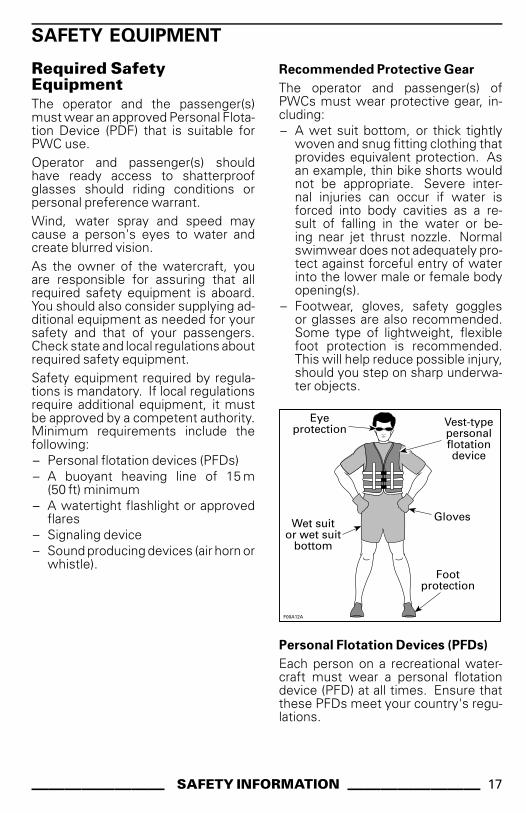
Recommended Protective Gear
The operator and passenger(s) ofPWCs must wear protective gear, in-cluding:– A wet suit bottom, or thick tightly
woven and snug fitting clothing thatprovides equivalent protection. Asan example, thin bike shorts wouldnot be appropriate. Severe inter-nal injuries can occur if water isforced into body cavities as a re-sult of falling in the water or be-ing near jet thrust nozzle. Normalswimwear does not adequately pro-tect against forceful entry of waterinto the lower male or female bodyopening(s).
– Footwear, gloves, safety gogglesor glasses are also recommended.Some type of lightweight, flexiblefoot protection is recommended.This will help reduce possible injury,should you step on sharp underwa-ter objects.
������
�� ���������
������� � ����������������������
����������������� �������!����"
���� ���������
Personal Flotation Devices (PFDs)
Each person on a recreational water-craft must wear a personal flotationdevice (PFD) at all times. Ensure thatthese PFDs meet your country's regu-lations.
________ SAFETY INFORMATION ________ 17
SAFETY EQUIPMENT
A PFD provides buoyancy to help keepthe head and face above the water, andto help maintain a satisfactory body po-sition while in the water. Body weightand age should be considered whenselecting a PFD. The buoyancy pro-vided by the PFD should support yourweight in water. The size of the PFDshould be appropriate for the wearer.Body weight and chest size are com-mon methods used to size PFDs. It isyour responsibility to ensure that youhave the proper number and types ofPFDs on board to comply with federaland local regulations, and that yourpassengers know where they are andhow to use them.
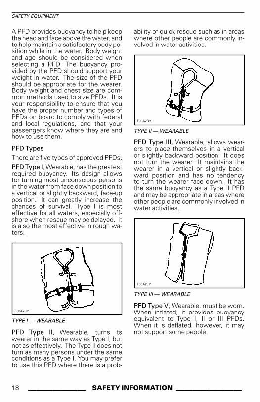
PFD TypesThere are five types of approved PFDs.PFD Type I, Wearable, has the greatestrequired buoyancy. Its design allowsfor turning most unconscious personsin the water from face down position toa vertical or slightly backward, face-upposition. It can greatly increase thechances of survival. Type I is mosteffective for all waters, especially off-shore when rescue may be delayed. Itis also the most effective in rough wa-ters.
�����#�
TYPE I — WEARABLE
PFD Type II, Wearable, turns itswearer in the same way as Type I, butnot as effectively. The Type Il does notturn as many persons under the sameconditions as a Type I. You may preferto use this PFD where there is a prob-
ability of quick rescue such as in areaswhere other people are commonly in-volved in water activities.
�����$�
TYPE II — WEARABLE
PFD Type III, Wearable, allows wear-ers to place themselves in a verticalor slightly backward position. It doesnot turn the wearer. It maintains thewearer in a vertical or slightly back-ward position and has no tendencyto turn the wearer face down. It hasthe same buoyancy as a Type Il PFDand may be appropriate in areas whereother people are commonly involved inwater activities.
�������
TYPE III — WEARABLE
PFD Type V, Wearable, must be worn.When inflated, it provides buoyancyequivalent to Type I, Il or III PFDs.When it is deflated, however, it maynot support some people.
18 _______ SAFETY INFORMATION ________
SAFETY EQUIPMENT
�������
TYPE V — WEARABLE
Helmets
Some Important ConsiderationsHelmets are designed to offer somedegree of protection in case of im-pacts to the head. In most motorizedsports, the benefits of wearing a hel-met clearly outweigh the drawbacks.However, in the case of motorized wa-tersports such as riding personal wa-tercraft, this is not necessarily true asthere are some particular risks associ-ated with the water.
BenefitsA helmet helps to reduce the risk ofinjury in case of a head impact againsta hard surface such as another craft inthe case of a collision. Similarly, a hel-met with a chin guard might help pre-vent injuries to the face, jaw or teeth.
RisksOn the other hand, in some situationswhen falling off the watercraft, hel-mets have a tendency to catch thewater, like a “bucket”, and put severestresses on the neck or spine. Thiscould result in choking, severe or per-manent neck or spine injury or death.Helmets may also interfere with pe-ripheral vision and hearing, or increasefatigue which, could contribute to in-crease the risk of a collision.
Weighing the Risks vs BenefitsIn order to decide whether or not youshould wear a helmet, it is best to con-sider the particular environment youwill be riding in, as well as other fac-tors such as personal experience. Willthere be a lot of traffic on the water?What is your riding style?
The Bottom LineSince each option minimizes somerisks, but increases others, beforeeach ride you must decide whetherto wear or not wear a helmet based onyour particular situation.If you decide to wear a helmet, youmust then decide what type is themost appropriate for the circum-stances. Look for helmets that meetDOT or Snell standards, and if possi-ble, choose one designed for motor-ized watersports.
Additional RecommendedEquipmentIt is recommended that you acquireadditional equipment for safe, enjoy-able cruising. This list, which is not allinclusive, includes items you shouldconsider acquiring.– Local map– First aid kit– Tow rope– Flares– Mooring cords.A cellular telephone in a waterproofbag or container has also been foundto be beneficial to boaters when in dis-tress or just for contacting someoneon shore.
________ SAFETY INFORMATION ________ 19
PRACTICE EXERCISES
It is always a good idea to practice andget familiar with all controls, functionsand handling characteristics of yourwatercraft before venturing on the wa-ter.Always secure the tether cord to theengine cut-off switch and the clip toyour PFD or a wrist strap.
Where to PracticeExercisesFind a suitable area to practice the ex-ercises. Ensure the area meet the fol-lowing requirements:– No traffic– No obstacles– No swimmers– No current– Ample space to maneuver– Water depth is adequate.
Practice ExercisesPractice alone the following exercises.
Turning
Practice turning in circles in both di-rections at slow speed. When com-fortable with the exercise, increasedifficulty by making some figure 8.When this is mastered, repeat theabove exercises but at increasedspeed.
Stopping Distances
Practice stopping the watercraft ina straight line at various speeds andbraking force.Remember that watercraft speed,load, water conditions, current andwind also affect stopping distances.
Reverse
Practice reverse operation to learnhow the watercraft operates in reverseand reacts with steering inputs.NOTE: Always perform this exerciseat slow speeds.
Avoiding an Obstacle
Practice obstacle avoidance (choose avirtual point on the water) by steeringthe watercraft and maintaining throt-tle.Repeat exercise, but this time releasethrottle while turning.NOTE: With this exercise, you willlearn that you need throttle to steer thewatercraft in a different direction.
Docking
Practice docking using the throttle, iBRlever and the steering to become famil-iar with the response of the PWC, andto develop good control skills.NOTE: Remember that steering direc-tion is reversed when backing.
Important Factors Not toNeglectIn addition, always remember that thefollowing conditions have a direct im-pact on how your watercraft will be-have and respond to different inputs:– Loads– Currents– Wind– Water conditions.Make sure to be alert to these condi-tions, and adapt accordingly. If pos-sible, practice further in these condi-tions.For delicate maneuvers, the best ad-vice is always to try to reduce yourspeed to a minimum.
20 _______ SAFETY INFORMATION ________
NAVIGATION RULES
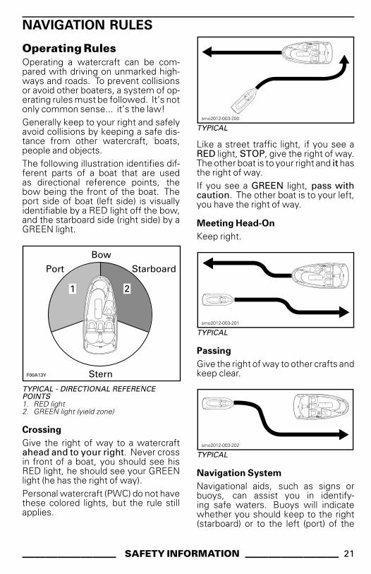
Operating RulesOperating a watercraft can be com-pared with driving on unmarked high-ways and roads. To prevent collisionsor avoid other boaters, a system of op-erating rules must be followed. It’s notonly common sense... it’s the law!Generally keep to your right and safelyavoid collisions by keeping a safe dis-tance from other watercraft, boats,people and objects.The following illustration identifies dif-ferent parts of a boat that are usedas directional reference points, thebow being the front of the boat. Theport side of boat (left side) is visuallyidentifiable by a RED light off the bow,and the starboard side (right side) by aGREEN light.
�����%�
&�� ��' �
&���
( �
��
TYPICAL - DIRECTIONAL REFERENCEPOINTS1. RED light2. GREEN light (yield zone)
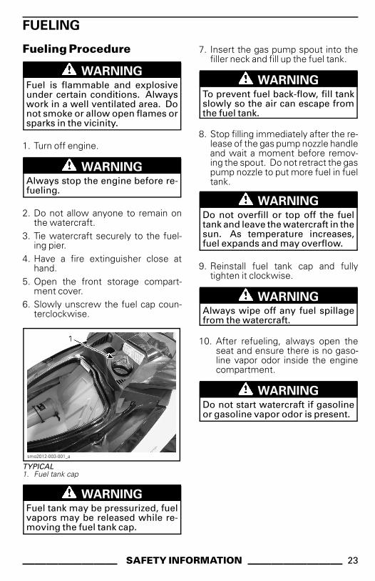
Crossing
Give the right of way to a watercraftahead and to your right. Never crossin front of a boat, you should see hisRED light, he should see your GREENlight (he has the right of way).Personal watercraft (PWC) do not havethese colored lights, but the rule stillapplies.
smo2012-003-200
TYPICAL
Like a street traffic light, if you see aRED light, STOP, give the right of way.The other boat is to your right and it hasthe right of way.If you see a GREEN light, pass withcaution. The other boat is to your left,you have the right of way.
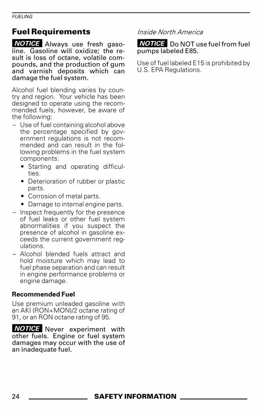
Meeting Head-On
Keep right.
smo2012-003-201
TYPICAL
Passing
Give the right of way to other crafts andkeep clear.
smo2012-003-202
TYPICAL
Navigation System
Navigational aids, such as signs orbuoys, can assist you in identify-ing safe waters. Buoys will indicatewhether you should keep to the right(starboard) or to the left (port) of the
________ SAFETY INFORMATION ________ 21
NAVIGATION RULES
buoy, or to which channel you can con-tinue. They may also indicate whetheryou are entering a restricted or con-trolled area such as a no wake or lowspeed zone. They may also indicatehazards or pertinent boating informa-tion. Markers may be located on shoreor on the water. They can also indi-cate speed limits, no power craft orboating, anchorage and other usefulinformation. (The shape of each typeof marker will provide assistance).Make sure you know and understandthe navigation system applicable tothe waterways where you intend touse the watercraft.
Collision Avoidance
Do not release the throttle when try-ing to steer away from an obstacle.Engine power and jet pump thrust isrequired to steer the watercraft.Always keep a constant lookout forother water users, other boats or ob-jects, especially when turning. Be alertfor conditions that may limit your visi-bility or block your vision of others.Respect the rights of other recreation-ists and/or bystanders and alwayskeep a safe distance from all otherwatercraft, boats, people and objects.Do not wake or wave jump, ride thesurf line or attempt to spray or splashothers with your watercraft. You maymisjudge the ability of the watercraftor your own riding skills and strike aboat, watercraft or person.This watercraft has the capability ofturning more sharply than other boats,however, unless in an emergency, donot negotiate sharp, high speed turns.Such maneuvers make it hard for oth-ers to avoid you or understand whereyou are going. Also, you and/or yourpassenger(s) could be thrown from thewatercraft.Unlike most other watercraft, thisPWC has a braking system (iBR).
When operating an iBR equipped wa-tercraft, be aware that other boats fol-lowing or operating in close proximitymay not be able to stop as quickly.When at speed and the brake is first ap-plied, a plume of water will shoot up inthe air behind the watercraft indicatinga braking manoeuvre.It is important to inform the operator ofa watercraft who intends to follow ina convoy formation of the braking andmaneuvering capability of your PWC,what the plume of water indicates, andthat a greater distance should be main-tained between both of you.Stopping distance will vary dependingon initial speed, load, wind and waterconditions.Although the preferable maneuver toavoid an obstacle is to steer away whileapplying throttle, the iBR can also beused by fully braking and turning in theappropriate direction to avoid the ob-stacle.
22 _______ SAFETY INFORMATION ________
FUELING
Fueling Procedure
WARNINGFuel is flammable and explosiveunder certain conditions. Alwayswork in a well ventilated area. Donot smoke or allow open flames orsparks in the vicinity.
1. Turn off engine.
WARNINGAlways stop the engine before re-fueling.
2. Do not allow anyone to remain onthe watercraft.
3. Tie watercraft securely to the fuel-ing pier.
4. Have a fire extinguisher close athand.
5. Open the front storage compart-ment cover.
6. Slowly unscrew the fuel cap coun-terclockwise.
smo2012-003-001_a
TYPICAL1. Fuel tank cap
WARNINGFuel tank may be pressurized, fuelvapors may be released while re-moving the fuel tank cap.
7. Insert the gas pump spout into thefiller neck and fill up the fuel tank.
WARNINGTo prevent fuel back-flow, fill tankslowly so the air can escape fromthe fuel tank.
8. Stop filling immediately after the re-lease of the gas pump nozzle handleand wait a moment before remov-ing the spout. Do not retract the gaspump nozzle to put more fuel in fueltank.
WARNINGDo not overfill or top off the fueltank and leave the watercraft in thesun. As temperature increases,fuel expands and may overflow.
9. Reinstall fuel tank cap and fullytighten it clockwise.
WARNINGAlways wipe off any fuel spillagefrom the watercraft.
10. After refueling, always open theseat and ensure there is no gaso-line vapor odor inside the enginecompartment.
WARNINGDo not start watercraft if gasolineor gasoline vapor odor is present.
________ SAFETY INFORMATION ________ 23
FUELING
Fuel RequirementsNOTICE Always use fresh gaso-
line. Gasoline will oxidize; the re-sult is loss of octane, volatile com-pounds, and the production of gumand varnish deposits which candamage the fuel system.
Alcohol fuel blending varies by coun-try and region. Your vehicle has beendesigned to operate using the recom-mended fuels, however, be aware ofthe following:– Use of fuel containing alcohol above
the percentage specified by gov-ernment regulations is not recom-mended and can result in the fol-lowing problems in the fuel systemcomponents:• Starting and operating difficul-
ties.• Deterioration of rubber or plastic
parts.• Corrosion of metal parts.• Damage to internal engine parts.
– Inspect frequently for the presenceof fuel leaks or other fuel systemabnormalities if you suspect thepresence of alcohol in gasoline ex-ceeds the current government reg-ulations.
– Alcohol blended fuels attract andhold moisture which may lead tofuel phase separation and can resultin engine performance problems orengine damage.
Recommended Fuel
Use premium unleaded gasoline withan AKI (RON+MON)/2 octane rating of91, or an RON octane rating of 95.
NOTICE Never experiment withother fuels. Engine or fuel systemdamages may occur with the use ofan inadequate fuel.
Inside North America
NOTICE Do NOT use fuel from fuelpumps labeled E85.
Use of fuel labeled E15 is prohibited byU.S. EPA Regulations.
24 _______ SAFETY INFORMATION ________
TRAILERING INFORMATION
NOTICE The span of the trailerwood bunks including bunk widthshould be adjusted to provide sup-port throughout the full length of thehull. The ends of both trailer woodbunks should not exceed the lengthof the watercraft.
Ensure the trailer wheels are posi-tioned so that the center of gravity ofthe watercraft is slightly ahead of thewheels to properly support the weightof the watercraft.
WARNINGNever tip this watercraft on end fortransporting. We recommend thatyou carry the watercraft in its nor-mal operating position.
Check the applicable laws and regula-tions in your area concerning towinga trailer, especially for the followingitems:– Brake system– Tow vehicle weight– Mirrors.Take the following precautions whentowing the watercraft:– Respect tow vehicle maximum
weight capacity and the tongueweight capacity as recommendedby manufacturer.
– Tie the watercraft to both front andrear (bow/stern) eyelets so that it isfirmly secured on the trailer. Use ad-ditional tie-downs if necessary.
– Ensure fuel tank cap, front stor-age compartment cover, glove boxcover and seat are properly latched.
– Observe trailering safety precau-tions.
NOTICE Do not route ropes ortie-downs over the seat or grabhandle as they could be perma-nently damaged. Wrap ropes ortie-downs with rags or similar pro-tectors where they can come intocontact with the watercraft body.
WARNINGMake sure seat is securely latchedprior to trailering.
A Sea-Doo cover can protect the wa-tercraft, particularly when driving ondirt roads, to prevent dirt entry throughthe air inlet openings.
WARNINGWhen trailering the watercraft,NEVER leave any equipment onthe watercraft.
________ SAFETY INFORMATION ________ 25
IMPORTANT ON-PRODUCT LABELS
Hang TagThis watercraft comes with a hang tag and labels containing important safety infor-mations.
219904038
HANG TAG - LOCATED ON HANDLEBAR
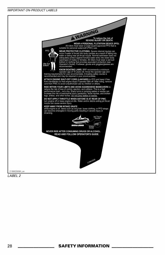
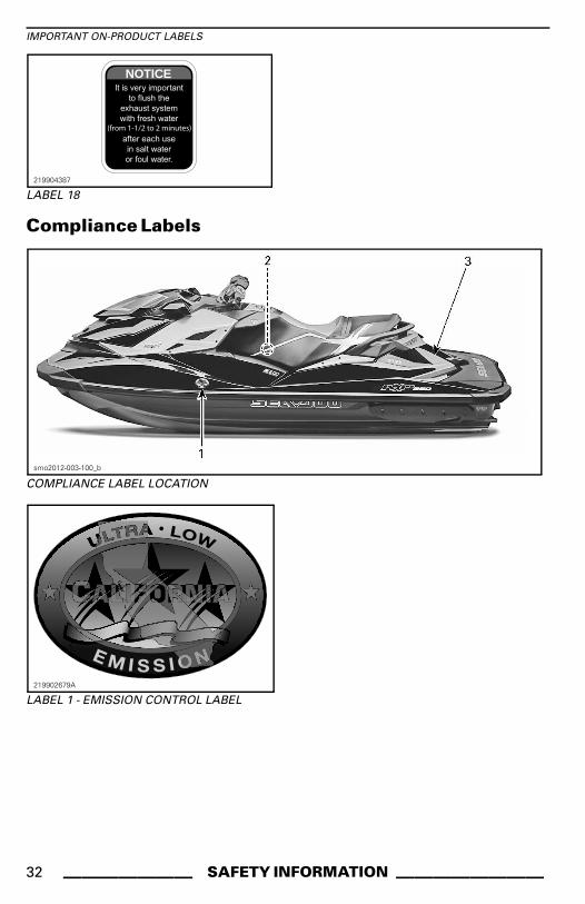
Watercraft Safety LabelsThese labels are affixed to the vehicle for the safety of the operator, passenger(2-UP) or bystandersThe labels illustrated on the following pages are on your watercraft. If missing ordamaged, they can be replaced free of charge. See an authorized Sea-Doo dealer.Please read the following labels carefully before operating this watercraft.NOTE: The first illustration of the watercraft indicates the approximate locationsof the various labels. A dotted line indicates that the label is not on the outer sur-face, and that the seat or a cover of some type must be opened to see the label.NOTE: In the event of any discrepancy between this guide and the vehicle, thesafety labels on the vehicle have precedence over the labels in this guide.
smo2012-003-100_g
WATERCRAFT SAFETY LABEL LOCATION
26 _______ SAFETY INFORMATION ________
IMPORTANT ON-PRODUCT LABELS
219904438
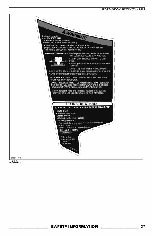
Collisions result in more INJURIES AND DEATHS than any other type of accident for personal watercraft (PWC).TO AVOID COLLISIONS: SCAN CONSTANTLY for people, objects, and other watercraft. Be alert for conditions that limit your visibility or block your vision of others.
OPERATE DEFENSIVELY at safe speeds and keep a safe distance away from people, objects, and other watercraft.• Do not follow directly behind PWCs or other boats.• Do not go near others to spray or splash them with water.• Avoid sharp turns or other maneuvers that
make it hard for others to avoid you or understand where you are going.• Avoid areas with submerged objects or shallow water.
TAKE EARLY ACTION to avoid collisions. Remember, PWCs and other boats do not have brakes.DO NOT RELEASE THROTTLE WHEN TRYING TO STEER away from objects – you need throttle to steer. Always check throttle and steering controls for proper operation before starting PWC.
Follow navigation rules and province / state and local laws that apply to PWCs. See Operator's Guide for more information.
IBR INTELLIGENT BRAKE AND REVERSE FUNCTIONS:
How to brake• Squeeze brake leverHow to reverse• Maintain brake lever engagedHow to go forward• Tap throttle lever to engage forward movement from neutral position. Squeeze throttle lever to accelerate.How to get to neutral•Tap brake lever
Refer to the operator's guide for more information.
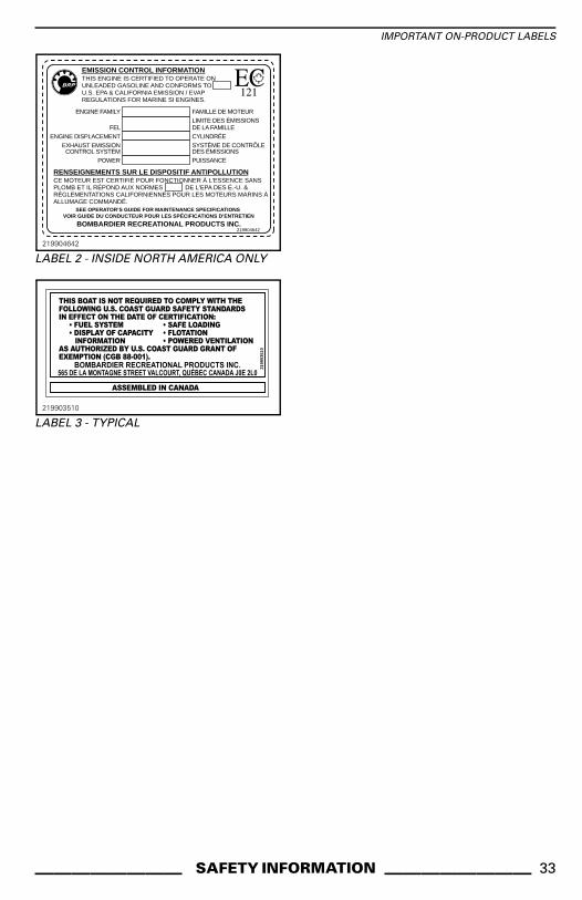
RENSEIGNEMENTS SUR LE DISPOSITIF ANTIPOLLUTIONCE MOTEUR EST CERTIFIÉ POUR FONCTIONNER À L'ESSENCE SANS PLOMB ET IL RÉPOND AUX NORMES DE L'EPA DES É.-U. & RÉGLEMENTATIONS CALIFORNIENNES POUR LES MOTEURS MARINS À ALLUMAGE COMMANDÉ.
EMISSION CONTROL INFORMATIONTHIS ENGINE IS CERTIFIED TO OPERATE ON UNLEADED GASOLINE AND CONFORMS TO U.S. EPA & CALIFORNIA EMISSION / EVAP REGULATIONS FOR MARINE SI ENGINES.
ENGINE FAMILY
FELENGINE DISPLACEMENT
EXHAUST EMISSIONCONTROL SYSTEM
POWER
FAMILLE DE MOTEURLIMITE DES ÉMISSIONSDE LA FAMILLECYLINDRÉESYSTÈME DE CONTRÔLE DES ÉMISSIONSPUISSANCE
BOMBARDIER RECREATIONAL PRODUCTS INC.
SEE OPERATOR’S GUIDE FOR MAINTENANCE SPECIFICATIONS VOIR GUIDE DU CONDUCTEUR POUR LES SPÉCIFICATIONS D’ENTRETIEN
219904642
219904642
LABEL 2 - INSIDE NORTH AMERICA ONLY21
9903
510
219903510
LABEL 3 - TYPICAL
________ SAFETY INFORMATION ________ 33
PRE-RIDE INSPECTION
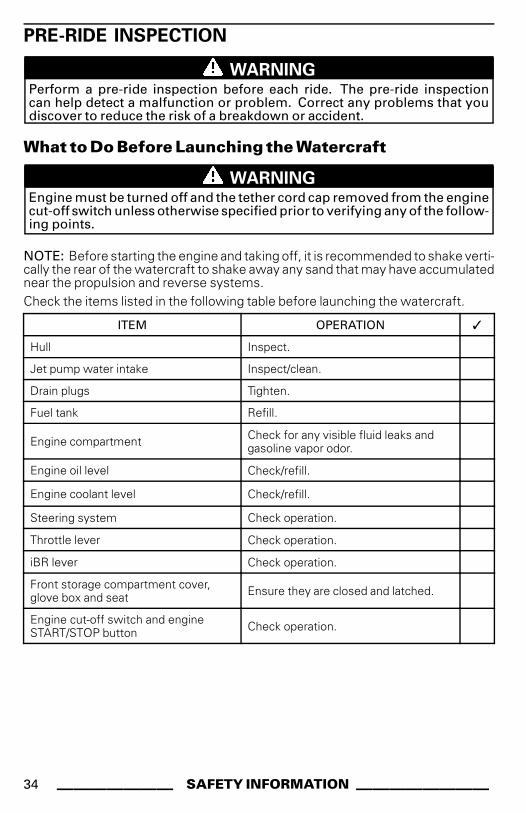
WARNINGPerform a pre-ride inspection before each ride. The pre-ride inspectioncan help detect a malfunction or problem. Correct any problems that youdiscover to reduce the risk of a breakdown or accident.
What to Do Before Launching the Watercraft
WARNINGEngine must be turned off and the tether cord cap removed from the enginecut-off switch unless otherwise specified prior to verifying any of the follow-ing points.
NOTE: Before starting the engine and taking off, it is recommended to shake verti-cally the rear of the watercraft to shake away any sand that may have accumulatednear the propulsion and reverse systems.Check the items listed in the following table before launching the watercraft.
ITEM OPERATION ✓
Hull Inspect.
Jet pump water intake Inspect/clean.
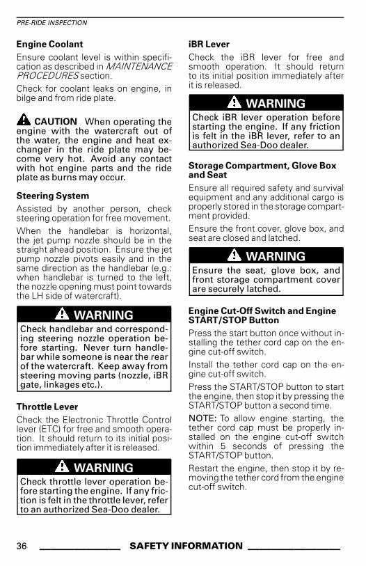
Drain plugs Tighten.
Fuel tank Refill.
Engine compartment Check for any visible fluid leaks andgasoline vapor odor.
Engine oil level Check/refill.
Engine coolant level Check/refill.
Steering system Check operation.
Throttle lever Check operation.
iBR lever Check operation.
Front storage compartment cover,glove box and seat Ensure they are closed and latched.
Engine cut-off switch and engineSTART/STOP button Check operation.
34 _______ SAFETY INFORMATION ________
PRE-RIDE INSPECTION
Hull
Inspect hull for cracks and other dam-ages.
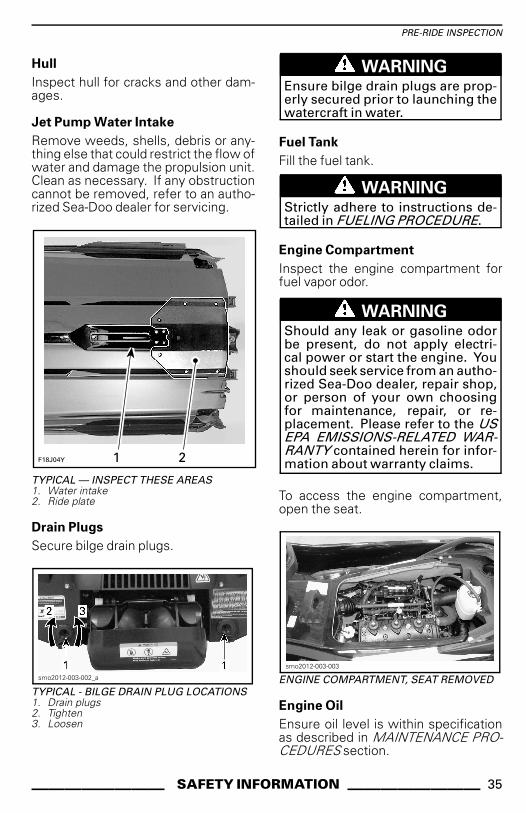
Jet Pump Water Intake
Remove weeds, shells, debris or any-thing else that could restrict the flow ofwater and damage the propulsion unit.Clean as necessary. If any obstructioncannot be removed, refer to an autho-rized Sea-Doo dealer for servicing.
��*+�,� ��
TYPICAL — INSPECT THESE AREAS1. Water intake2. Ride plate
WARNINGEnsure bilge drain plugs are prop-erly secured prior to launching thewatercraft in water.
Fuel Tank
Fill the fuel tank.
WARNINGStrictly adhere to instructions de-tailed in FUELING PROCEDURE.
Engine Compartment
Inspect the engine compartment forfuel vapor odor.
WARNINGShould any leak or gasoline odorbe present, do not apply electri-cal power or start the engine. Youshould seek service from an autho-rized Sea-Doo dealer, repair shop,or person of your own choosingfor maintenance, repair, or re-placement. Please refer to the USEPA EMISSIONS-RELATED WAR-RANTY contained herein for infor-mation about warranty claims.
To access the engine compartment,open the seat.
smo2012-003-003
ENGINE COMPARTMENT, SEAT REMOVED
Engine Oil
Ensure oil level is within specificationas described in MAINTENANCE PRO-CEDURES section.
________ SAFETY INFORMATION ________ 35
PRE-RIDE INSPECTION
Engine Coolant
Ensure coolant level is within specifi-cation as described in MAINTENANCEPROCEDURES section.Check for coolant leaks on engine, inbilge and from ride plate.
CAUTION When operating theengine with the watercraft out ofthe water, the engine and heat ex-changer in the ride plate may be-come very hot. Avoid any contactwith hot engine parts and the rideplate as burns may occur.
Steering System
Assisted by another person, checksteering operation for free movement.When the handlebar is horizontal,the jet pump nozzle should be in thestraight ahead position. Ensure the jetpump nozzle pivots easily and in thesame direction as the handlebar (e.g.:when handlebar is turned to the left,the nozzle opening must point towardsthe LH side of watercraft).
WARNINGCheck handlebar and correspond-ing steering nozzle operation be-fore starting. Never turn handle-bar while someone is near the rearof the watercraft. Keep away fromsteering moving parts (nozzle, iBRgate, linkages etc.).
Throttle Lever
Check the Electronic Throttle Controllever (ETC) for free and smooth opera-tion. It should return to its initial posi-tion immediately after it is released.
WARNINGCheck throttle lever operation be-fore starting the engine. If any fric-tion is felt in the throttle lever, referto an authorized Sea-Doo dealer.
iBR Lever
Check the iBR lever for free andsmooth operation. It should returnto its initial position immediately afterit is released.
WARNINGCheck iBR lever operation beforestarting the engine. If any frictionis felt in the iBR lever, refer to anauthorized Sea-Doo dealer.
Storage Compartment, Glove Boxand Seat
Ensure all required safety and survivalequipment and any additional cargo isproperly stored in the storage compart-ment provided.Ensure the front cover, glove box, andseat are closed and latched.
Press the start button once without in-stalling the tether cord cap on the en-gine cut-off switch.Install the tether cord cap on the en-gine cut-off switch.Press the START/STOP button to startthe engine, then stop it by pressing theSTART/STOP button a second time.NOTE: To allow engine starting, thetether cord cap must be properly in-stalled on the engine cut-off switchwithin 5 seconds of pressing theSTART/STOP button.Restart the engine, then stop it by re-moving the tether cord from the enginecut-off switch.
36 _______ SAFETY INFORMATION ________
PRE-RIDE INSPECTION
WARNINGShould the tether cord cap beloose or fail to remain on the en-gine cut-off switch, replace thetether cord immediately in orderto avoid unsafe use. If remov-ing the tether cord cap from theengine cut-off switch or pressingthe START/STOP button does notstop the engine, do not use thewatercraft. See your authorizedSea-Doo dealer.
What to Do AfterLaunching the WatercraftCheck the items listed in the follow-ing table after launching the watercraftand before going for a ride.
ITEM OPERATION ✓
InformationCenter Check operation.
Intelligent Brakeand ReverseSystem (iBR)
Check operation.
Variable TrimSystem (VTS) (asapplicable)
Check operation.
Information Center (Gauge)
1. Press START/STOP button and in-stall the tether cord cap on the en-gine cut-off switch.
2. As the information center cyclesthrough its self-test function, en-sure all indications come on.
WARNINGAlways attach the tether cord clipto your PFD or wrist (wrist strap re-quired).
iBR System
NOTICE Ensure there is sufficientspace ahead and behind watercraftto safely carry out the iBR systemtest to avoid a collision. Watercraftwill move during test.
1. Remove the moorings securing thewatercraft to the dock.
2. Start the engine and ensure the wa-tercraft does not move.
3. On the left handlebar, depress theiBR lever completely in, the wa-tercraft should move slowly back-wards.
4. Release the iBR lever, there shouldnot be any reverse thrust.
WARNINGAlways ensure proper iBR systemoperation before taking the water-craft out for a ride.
Variable Trim System (VTS)
With the engine running in forward po-sition, use the VTS system to movethe jet pump nozzle up and down alter-nately to check VTS operation. Con-firm the VTS position indicator move-ment in the information center.Also test the VTS preset trim positionsby double clicking the VTS UP/DOWNbutton (as applicable to model).Refer to OPERATING INSTRUCTIONSsubsection for detailed instructions.
________ SAFETY INFORMATION ________ 37
PRE-RIDE INSPECTION
This page is
intentionally blank
38 _______ SAFETY INFORMATION ________
WATERCRAFTINFORMATION
_______________ 39
CONTROLS
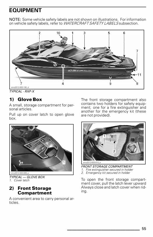
NOTE: Some vehicle safety labels are not shown on illustrations. For informationon vehicle safety labels, refer to WATERCRAFT SAFETY LABELS subsection.
smo2012-003-101_a
RXP-X
NOTE: Some controls, indications,functions and features described inthis section may not apply to everyPWC model, or may be available as anoption.
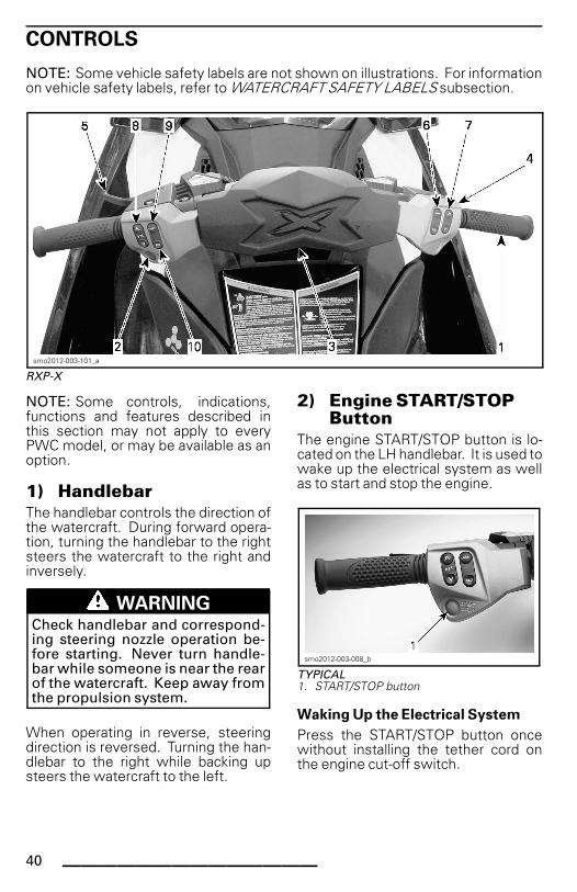
1) HandlebarThe handlebar controls the direction ofthe watercraft. During forward opera-tion, turning the handlebar to the rightsteers the watercraft to the right andinversely.
WARNINGCheck handlebar and correspond-ing steering nozzle operation be-fore starting. Never turn handle-bar while someone is near the rearof the watercraft. Keep away fromthe propulsion system.
When operating in reverse, steeringdirection is reversed. Turning the han-dlebar to the right while backing upsteers the watercraft to the left.
2) Engine START/STOPButton
The engine START/STOP button is lo-cated on the LH handlebar. It is used towake up the electrical system as wellas to start and stop the engine.
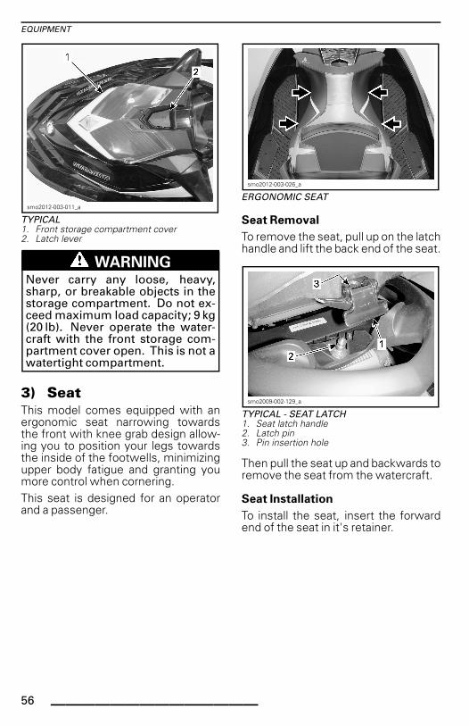
smo2012-003-008_b
TYPICAL1. START/STOP button
Waking Up the Electrical System
Press the START/STOP button oncewithout installing the tether cord onthe engine cut-off switch.
40 ______________
CONTROLS
This will power up the electrical sys-tem; the information center will cyclethrough a self-test function and willthen go blank after a few seconds.The electrical system will stay pow-ered up for approximately 3 minutesafter the START/STOP button was de-pressed.NOTE: If the START/STOP button ispressed and held without the tethercord installed, the information cen-ter displays will stay on as long as theSTART/STOP button is held.
Engine Starting and Stopping
Refer to OPERATING INSTRUCTIONSsubsection for detailed instructions.
3) Engine Cut-Off SwitchTo allow engine starting, the tethercord cap must be securely snappedonto the engine cut-off switch.
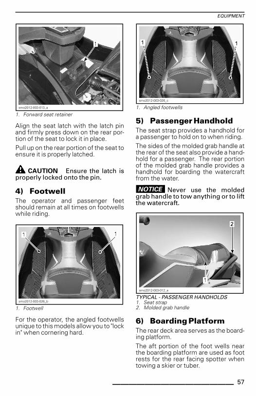
smo2012-003-025_a
TYPICAL1. Engine cut-off switch
WARNINGAlways attach the tether cord clipto the operator's personal flota-tion device (PFD) or wrist (wriststrap required).
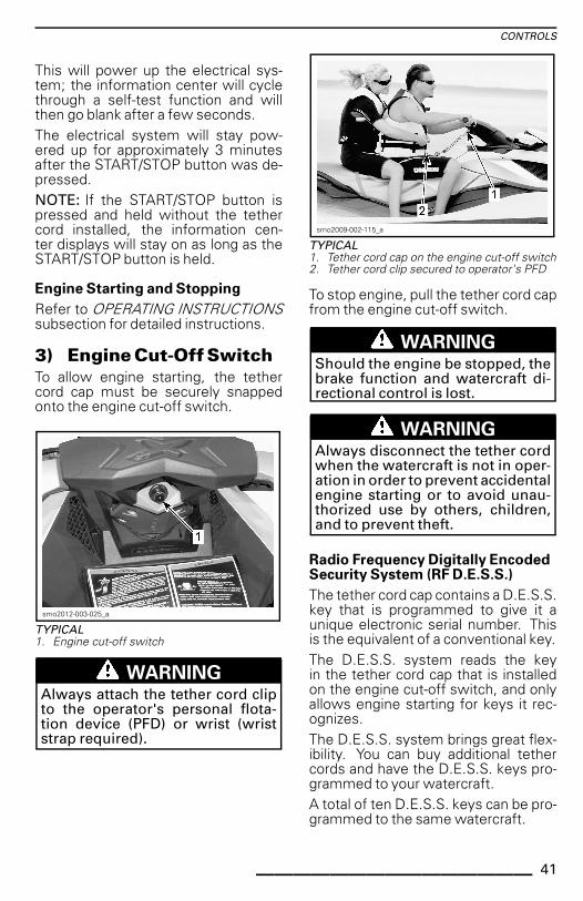
smo2009-002-115_a
TYPICAL1. Tether cord cap on the engine cut-off switch2. Tether cord clip secured to operator's PFD
To stop engine, pull the tether cord capfrom the engine cut-off switch.
WARNINGShould the engine be stopped, thebrake function and watercraft di-rectional control is lost.
WARNINGAlways disconnect the tether cordwhen the watercraft is not in oper-ation in order to prevent accidentalengine starting or to avoid unau-thorized use by others, children,and to prevent theft.
Radio Frequency Digitally EncodedSecurity System (RF D.E.S.S.)
The tether cord cap contains a D.E.S.S.key that is programmed to give it aunique electronic serial number. Thisis the equivalent of a conventional key.The D.E.S.S. system reads the keyin the tether cord cap that is installedon the engine cut-off switch, and onlyallows engine starting for keys it rec-ognizes.The D.E.S.S. system brings great flex-ibility. You can buy additional tethercords and have the D.E.S.S. keys pro-grammed to your watercraft.A total of ten D.E.S.S. keys can be pro-grammed to the same watercraft.
_______________ 41
CONTROLS
To have a key programmed to yourwatercraft, see your authorized BRPSea-Doo dealer.
RF D.E.S.S. Key RecognitionTwo short beeps indicate the systemis ready to allow engine starting. Oth-erwise, refer to the TROUBLESHOOT-ING section.
RF D.E.S.S. Key TypesTwo types of keys can be used:– Normal key– Learning key.To ease key type recognition, thetether cord float comes in differentcolors.
KEY TYPE FLOAT COLOR
Normal Yellow or Black
Learning Green
The information center displays thetype of key used.
������������
KEY TYPE RECOGNITION MESSAGE
NORMAL KEY or LEARNING KEY
The SEA-DOO learning key, limits thespeed of the watercraft and the en-gine torque, therefore enabling firsttime users and less experienced op-erators to learn how to operate thewatercraft while gaining the necessaryconfidence and control.The learning mode also offers the pos-sibility of setting the maximum speedof the watercraft.
Refer to OPERATING MODES subsec-tion for details.
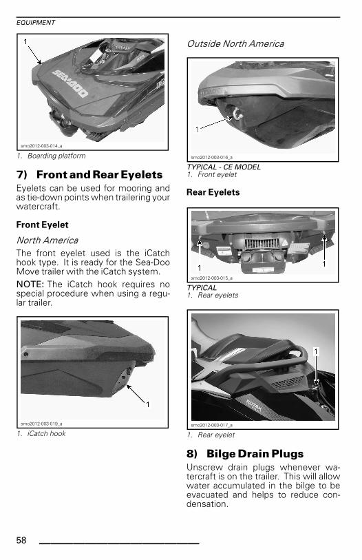
4) Throttle LeverThe throttle lever on the RH handle-bar electronically controls the enginespeed.To increase or maintain watercraftspeed, pull on the throttle lever withyour finger.To decrease watercraft speed, releasethe throttle lever.
smo2012-003-005_a
TYPICAL1. Throttle lever2. To accelerate3. To decelerate
The throttle lever is spring loaded andshould return to rest position (idle)when not pressed.
5) iBR Lever (intelligentBrake and Reverse)
The iBR lever on the LH handlebar canelectronically command:– Reverse– Neutral– Braking.NOTE: A minimum of 25% lever travelis required to activate iBR functions.
42 ______________
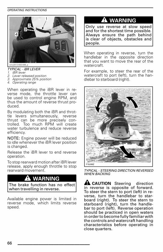
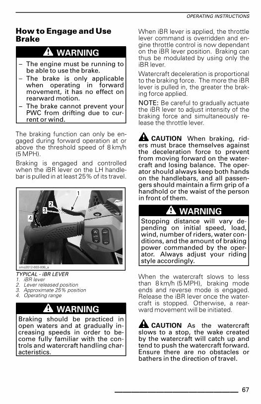
CONTROLS
smo2012-003-006_a
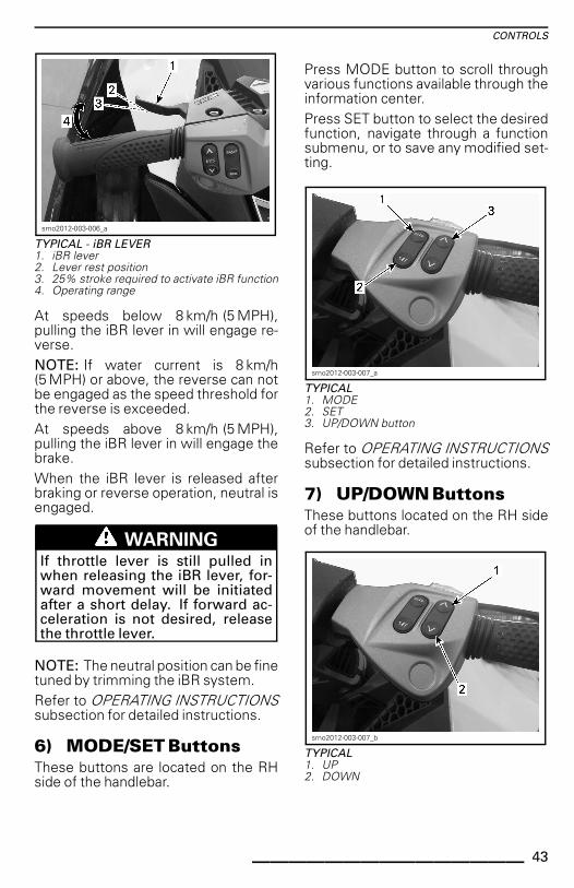
TYPICAL - iBR LEVER1. iBR lever2. Lever rest position3. 25% stroke required to activate iBR function4. Operating range
At speeds below 8 km/h (5 MPH),pulling the iBR lever in will engage re-verse.NOTE: If water current is 8 km/h(5 MPH) or above, the reverse can notbe engaged as the speed threshold forthe reverse is exceeded.At speeds above 8 km/h (5 MPH),pulling the iBR lever in will engage thebrake.When the iBR lever is released afterbraking or reverse operation, neutral isengaged.
WARNINGIf throttle lever is still pulled inwhen releasing the iBR lever, for-ward movement will be initiatedafter a short delay. If forward ac-celeration is not desired, releasethe throttle lever.
NOTE: The neutral position can be finetuned by trimming the iBR system.Refer to OPERATING INSTRUCTIONSsubsection for detailed instructions.
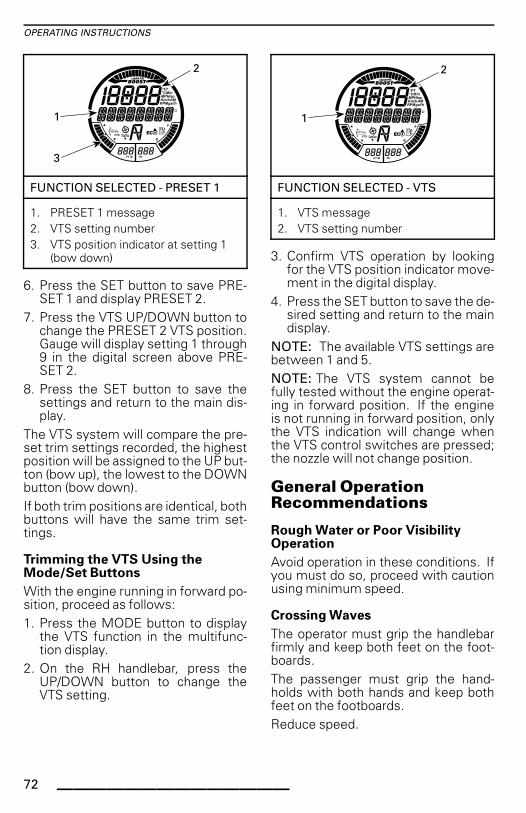
6) MODE/SET ButtonsThese buttons are located on the RHside of the handlebar.
Press MODE button to scroll throughvarious functions available through theinformation center.Press SET button to select the desiredfunction, navigate through a functionsubmenu, or to save any modified set-ting.
smo2012-003-007_a
TYPICAL1. MODE2. SET3. UP/DOWN button
Refer to OPERATING INSTRUCTIONSsubsection for detailed instructions.
7) UP/DOWN ButtonsThese buttons located on the RH sideof the handlebar.
smo2012-003-007_b
TYPICAL1. UP2. DOWN
_______________ 43
CONTROLS
The UP/DOWN buttons are used tomake a selection or change a settingthrough the information center suchas:– Gauge functions– iBR neutral adjustment.
8) VTS Button (VariableTrim System)
The VTS button is located on the LHhandlebar.
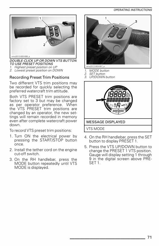
smo2012-003-008_a
TYPICAL - VTS CONTROL BUTTON1. Bow up2. Bow down
This model watercraft is equipped witha programmable high performanceVTS.It provides watercraft pitch trim adjust-ments by adjusting the vertical positionof the jet nozzle.The VTS can be electrically trimmed tothe desired attitude, or to one of twopreset trim positions.Press the VTS control button(up/down) to adjust the riding atti-tude of the watercraft.Refer to OPERATING INSTRUCTIONSsubsection for details.
9) Sport ButtonThe Sport button is located on the LHhandlebar.
smo2012-003-008_e
1. Sport button
It is used to activate or deactivateSPORT mode.Refer to OPERATING MODES subsec-tion for details.
10) ECO ButtonThe ECO button is located on the LHhandlebar.
smo2012-003-008_d
1. ECO button
It is used to activate or deactivate ECOmode.Refer to OPERATING MODES subsec-tion for details.
44 ______________
INFORMATION CENTER (GAUGES)
WARNINGDo not adjust the display while riding, you could lose control.
Information Center Description
56
1 3 15 2
14 12
13
84 49
smo2012-003-300_a
1) SpeedometerThe speedometer, located in the LHside of the information center, pro-vides an analog indication of the speedof the watercraft in miles per hour(MPH) and kilometers per hour (km/h).The speed indication is based on a GPS(Global Positioning System) incorpo-rated within the information center.If for some reason the GPS signal islost, a default mode is used whereby,the speed is calculated using infor-mation received from other systemsto provide an estimated watercraftspeed.
2) TachometerThe tachometer provides an analog in-dication of the revolutions per minute(RPM) of the engine. Multiply the in-dicated number by 1000 to obtain theactual engine RPM.
3) Multifunction GaugeThe multifunction gauge, located in thecenter of the information center, is ca-pable of displaying different indicationssimultaneously.Numerical and multifunction displaysin the digital screen indicator can beused to display various indications, orfor selecting modes of operation andchanging settings as explained in theirrespective sections.
_______________ 45
INFORMATION CENTER (GAUGES)
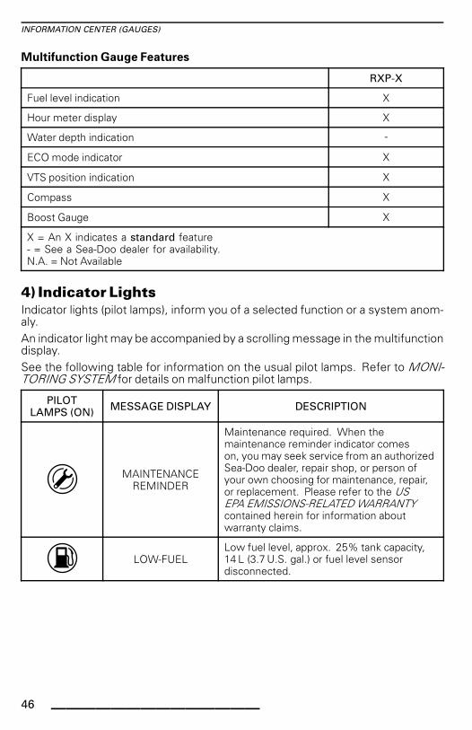
Multifunction Gauge Features
RXP-X
Fuel level indication X
Hour meter display X
Water depth indication -
ECO mode indicator X
VTS position indication X
Compass X
Boost Gauge X
X = An X indicates a standard feature- = See a Sea-Doo dealer for availability.N.A. = Not Available
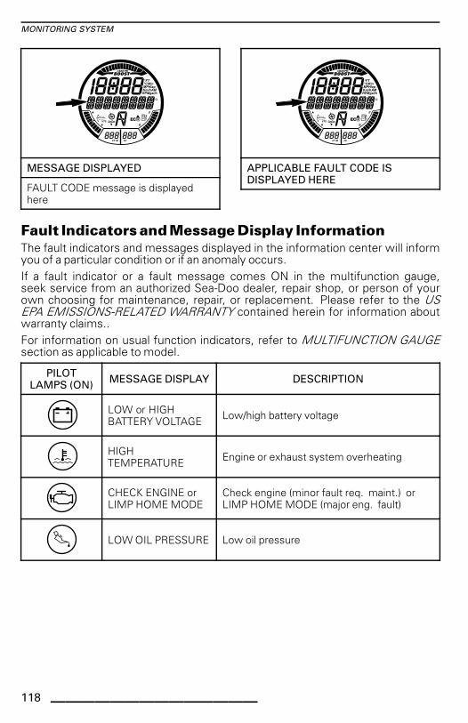
4) Indicator LightsIndicator lights (pilot lamps), inform you of a selected function or a system anom-aly.An indicator light may be accompanied by a scrolling message in the multifunctiondisplay.See the following table for information on the usual pilot lamps. Refer to MONI-TORING SYSTEM for details on malfunction pilot lamps.
PILOTLAMPS (ON) MESSAGE DISPLAY DESCRIPTION
MAINTENANCEREMINDER
Maintenance required. When themaintenance reminder indicator comeson, you may seek service from an authorizedSea-Doo dealer, repair shop, or person ofyour own choosing for maintenance, repair,or replacement. Please refer to the USEPA EMISSIONS-RELATED WARRANTYcontained herein for information aboutwarranty claims.
LOW-FUELLow fuel level, approx. 25% tank capacity,14 L (3.7 U.S. gal.) or fuel level sensordisconnected.
46 ______________
INFORMATION CENTER (GAUGES)
PILOTLAMPS (ON) MESSAGE DISPLAY DESCRIPTION
No message Feature not active on this model.
No message Feature not active on this model.
���������
Scrolling SPORTMODE messages
Sport Mode activated. Refer to OPERATINGMODES subsection.
5) Fuel Level IndicationA bar gauge located in the bottom RHside of the multifunction display con-tinuously indicates the amount of fuelin the fuel tank while riding.
������������
FUEL LEVEL INDICATION
When the fuel tank is full, 8 segments(bars) of the indicator are turned on.The top segment is not used.
Low Fuel Level Warning
It is active when there is only 2 seg-ments of fuel indicated (approxi-mately 25% fuel tank capacity or 14 L(3.7 U.S. gal.).
LOW FUEL LEVEL WARNING
Last 2 fuel gaugesegments
Fuel tank symbol (LCD)Flashing
Audible warning (onelong beep)
Scrolling LOW FUELWARNING message
Periodically
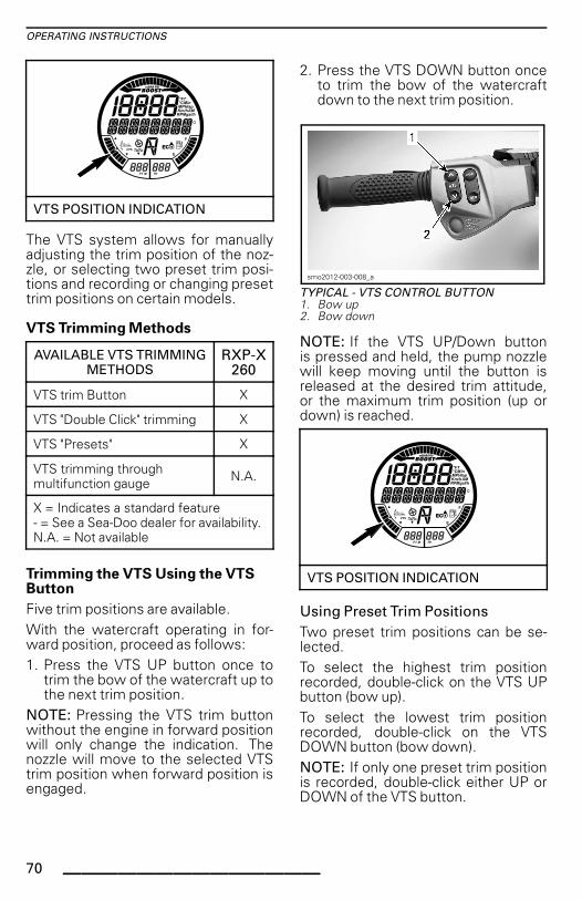
6) VTS PositionThe VTS position indication located inthe bottom LH side of the digital screenshows the riding attitude of the water-craft.A single segment of a bar gauge typeindicator is turned on to indicate the rel-ative position of the watercraft bow.
������������
VTS POSITION INDICATION
Refer to OPERATING INSTRUCTIONSfor more details on using the VTS.
_______________ 47
INFORMATION CENTER (GAUGES)
7) iS PositionNot available for this model.
8) Numerical DisplayThe numerical display is used to pro-vide a variety of indications as selectedby the operator using the DISPLAYfunction in the multifunction display.
������������
NUMERICAL DISPLAY
The available indications are depen-dent on the watercraft model or optioninstalled.
AVAILABLEINDICATIONS IN
NUMERICAL DISPLAYRXP-X
Watercraft speed Indicationby default
Engine RPM X
Engine temperature X
Lake water temperature N.A.
Clock X
Learning key settings X
CRUISE SPEED setting -
SLOW SPEED MODEsetting
-
VTS preset X
VTS settings (throughgauge) N.A.
SKI MODE settings N.A.
Fuel consumption(instant and average) X
AVAILABLEINDICATIONS IN
NUMERICAL DISPLAYRXP-X
Fuel autonomy(distance and time toempty)
X
Lap timer X
Top speed/RPMAverage speed/RPM X
Altitude N.A.
X = An X indicates a standard feature- = See a Sea-Doo dealer for availability.N.A. = Not Available
When the information center is firstpowered up, the numerical display de-faults to the last selected indication.
9) Multifunction DisplayThe multifunction display is used to:– Display the WELCOME message
on power up.– Display the KEY recognition mes-
sage.– Provide various indications as se-
lected by the operator.– Activating and setting various func-
tions and modes of operation.– Display scrolling messages of func-
tion activation or system faults.– Display fault codes.NOTE: The default indication in themultifunction display is the compassdirection.
10) Water Depth DisplayNot available for this model.
11) Water TemperatureDisplayNot available for this model.
12)HourMeterDisplay (HR)Continuously displays the accumu-lated engine hours.
48 ______________
INFORMATION CENTER (GAUGES)
������������
HOUR METER DISPLAY
13) iBR PositionProvides an indication of the iBR gateposition.– N (neutral)– F (forward)– R (reverse).
������������
iBR POSITION INDICATOR
14) CompassA GPS incorporated in the informationcenter provides the indication in themultifunction display.The cardinal points, intermediate car-dinal points, as well as the azimuth thewatercraft is travelling are displayedin the multifunction display by defaultwhen the watercraft is moving.For a compass indication to be dis-played, the GPS must have a good linkwith the navigation satellites.This is confirmed when the COMPASSactive indicator is visible in the digitalscreen.
������������
�
COMPASS
1. Compass indication2. Compass active indicator
NOTE: The compass indication is onlyavailable above 5 km/h (3 MPH).
WARNINGUse the compass as a guide only.Not to be used for precision navi-gation purposes.
15) Boost Gauge
������������
BOOST INDICATOR
The boost gauge indicates the mani-fold pressure of the engine providedby the supercharger.
Navigating theMultifunction DisplayWhen the electrical system is pow-ered up and the cluster has completedits self test function, a WELCOMEABOARD SEA-DOO scrolling mes-sage will appear for a few seconds.After the welcome message, nothingwill appear in the display until the wa-tercraft is operated.
_______________ 49
INFORMATION CENTER (GAUGES)
When the watercraft is being oper-ated, the multifunction display pro-vides an indication of compass headingor scrolling messages from the moni-toring system.The multifunction display is also usedto display a menu for the selection ofvarious functions which, permit chang-ing the numerical display indication,system modes of operation, settings,active system fault codes, and a laptimer.
WARNINGSelecting various numerical dis-plays, system modes of opera-tion or changing settings shouldonly be carried out with the water-craft stopped. Selecting these var-ious functions while operating thewatercraft at speed is not recom-mended as it deters your attentionfrom situational awareness.
������������
MULTIFUNCTION DISPLAY
NOTE: To change the unit of measure-ment or the language displayed, seeyour authorized Sea-Doo dealer.
Selecting Functions
When operating at speed, the multi-function display normally provides anindication of the compass direction andazimuth the watercraft is traveling.To select the various functions avail-able through the multifunction display,press the MODE button repeatedly un-til the desired function is visible:– LAP TIME
– FUEL CONSUMPTION– VTS MODE– DISPLAY– FAULT CODES– KEY MODE– SETTINGS.Then press the SET button to enter thatfunction.NOTE: The fault code function is onlyavailable when there is an active fault.The settings function is only availablewhen the engine is shut off. The keymode function is only available with anormal key.
Function Description
Lap TimerThe lap timer can be used to record upto 50 individual lap times.To activate and use the lap timer, carryout the following:1. Press the MODE button repeatedly
until LAP TIME is visible in the multi-function display.
������������
MESSAGE DISPLAYED
LAP TIME
2. Press the SET button to enter thefunction, the lap timer will be acti-vated and visible in the display.
50 ______________
INFORMATION CENTER (GAUGES)
������������
�
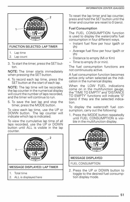
FUNCTION SELECTED: LAP TIMER
1. Lap time2. Lap count
3. To start the timer, press the SET but-ton.
NOTE: The timer starts immediatelywhen pressing the SET button.4. To record each lap time, press the
SET button at the start of each lap.NOTE: The lap time will be recorded,the lap counter in the numerical displaywill count the number of laps recorded,and the timer will continue to run.5. To save the last lap and stop the
timer, press the MODE button.To view each lap time, use the UP orDOWN button. The lap counter willindicate which lap is indicated.To view the cumulative lap time of alllaps recorded, use the UP or DOWNbutton until ALL is visible in the lapcounter.
������������
�
MESSAGE DISPLAYED: LAP TIMER
1. Total time2. ALL is displayed here
To reset the lap timer and lap counter,press and hold the SET button until thetimer and counter are reset to 0 (zero).
Fuel ConsumptionThe FUEL CONSUMPTION functionis used to display the watercrafts fuelconsumption in four different ways.– Instant fuel flow per hour (gal/h or
l/h)– Average fuel flow per hour (gal/h or
l/h)– Distance to empty (Mi or Km)– Time to empty (h or min).The fuel consumption functions arenot continuously active.A fuel consumption function becomesactive only when selected as the indi-cation in the numerical display.When the LOW FUEL indicationscome on in the multifunction gauge,the "TIME TO EMPTY" and "DISTANCETO EMPTY" functions will indicate "0"(zero) if they are the selected indica-tion.To display the watercraft fuel con-sumption, carry out the following:1. Press the MODE button repeatedly
until FUEL CONSUMPTION is visi-ble in the multifunction display.
������������
MESSAGE DISPLAYED
FUEL CONSUMPTION
2. Press the UP or DOWN button totoggle to the desired fuel consump-tion display mode.
_______________ 51
INFORMATION CENTER (GAUGES)
������������
�
FUEL CONSUMPTION DISPLAYMODE
1. INSTANT FUEL CONSUMPTIONmessage
2. Fuel consumption value
3. Press the SET button to save thesetting and return to the main dis-play.
NOTE: The fuel consumption valuewill be displayed in the numerical dis-play. Double click the SET button toreset the average fuel consumption in-dication. The display will momentarilyindicate zero (0).
VTS ModeThe VTS MODE function is used tomanually set the VTS or change VTSPRESET settings. Refer to OPERAT-ING INSTRUCTIONS subsection fordetails.
DisplayThe DISPLAY function is used tochange the indication in the numericaldisplay. Refer to CHANGING NUMER-ICAL DISPLAY INDICATION.
Fault CodesThe FAULT CODES function is usedto display active fault codes. Refer toMONITORING SYSTEM subsection.
Key ModeThe KEY MODE function is used forchanging LEARNING key settings. Re-fer to OPERATING MODES subsectionfor details.
SettingsThe SETTINGS function is used for:– Clock setting. Refer to MULTI-
FUNCTION GAUGE SETUP– iBR override function for mainte-
nance.
Changing NumericalDisplay IndicationTo change the indication in the numeri-cal display, carry out the following:1. Press the MODE button on the RH
handlebar repeatedly until DISPLAYis visible in the multifunction display.
������������
MESSAGE DISPLAYED
DISPLAY
2. Press the SET button to enter theDISPLAY function.
3. Press the UP or DOWN button untilthe preferred indication appears.– RPM– SPEED– ENGINE TEMP– TOP SPEED– AVG SPEED– TOP RPM– AVG RPM– CLOCK.
52 ______________
INFORMATION CENTER (GAUGES)
������������
�
NUMERICAL DISPLAY SELECTION
1. Type of selected numerical displayindication
2. Applicable value
4. Press the SET button to select andsave the preferred indication, orwait for the display function to timeout. The last indication visible willbe automatically saved.
The following abbreviations are used inthe numerical display:– FT or M– RPM– MPH or Km/h– °F or °C– AM or PM– Gal/h or l/h.
Resetting NumericalDisplay IndicationThe following numerical display indica-tions can be reset:– Average fuel consumption– Top speed– Average speed– Top RPM– Average RPM.To reset indications, double click theSET button. The numerical display willmomentarily indicate zero (0).NOTE: Each of these functions be-come active ONLY when selected asthe numerical display indication.
Multifunction GaugeSetup
Changing Clock Setting
1. Press the MODE button repeatedlyuntil SETTINGS is visible in the mul-tifunction display.
������������
MESSAGE DISPLAYED
SETTINGS
2. Press the UP or DOWN button re-peatedly until CLOCK is visible.
������������
�
FUNCTION SELECTED - CLOCK
1. CLOCK message2. Time
3. Press the SET button to enter thefunction. CHANGE CLOCK OFF-SET message will be displayed.
_______________ 53
INFORMATION CENTER (GAUGES)
������������
�
FUNCTION SELECTED - CHANGECLOCK OFFSET
1. CHANGE CLOCK OFFSET message2. Time
4. Press the UP or DOWN button toadjust the clock to the correct localtime.
5. Press the SET button to save thesetting and return to the main dis-play.
NOTE: The clock uses the GPS sig-nal to maintain the appropriate timereferenced to Greenwich Mean Time(GMT). When setting the clock, onlythe hour indication may be changed.
Units of Measurement andLanguage Setting
The multifunction gauge is capable ofdisplaying information in metric or im-perial units and in various languages.To change the units of measurementor to change the language displayedin the multifunction gauge, see yourauthorized Sea-Doo dealer.
54 ______________
EQUIPMENT
NOTE: Some vehicle safety labels are not shown on illustrations. For informationon vehicle safety labels, refer to WATERCRAFT SAFETY LABELS subsection.
smo2012-003-100_d
TYPICAL - RXP-X
1) Glove BoxA small, storage compartment for per-sonal articles.Pull up on cover latch to open glovebox.
smo2012-003-009_a
TYPICAL — GLOVE BOX1. Cover latch
2) Front StorageCompartment
A convenient area to carry personal ar-ticles.
The front storage compartment alsocontains two holders for safety equip-ment; one for a fire extinguisher andanother for the emergency kit (theseare not provided).
smo2012-003-010_a
FRONT STORAGE COMPARTMENT1. Fire extinguisher secured in holder2. Emergency kit secured in holder
To open the front storage compart-ment cover, pull the latch lever upwardAlways close and latch cover when rid-ing.
_______________ 55
EQUIPMENT
smo2012-003-011_a
TYPICAL1. Front storage compartment cover2. Latch lever
WARNINGNever carry any loose, heavy,sharp, or breakable objects in thestorage compartment. Do not ex-ceed maximum load capacity; 9 kg(20 lb). Never operate the water-craft with the front storage com-partment cover open. This is not awatertight compartment.
3) SeatThis model comes equipped with anergonomic seat narrowing towardsthe front with knee grab design allow-ing you to position your legs towardsthe inside of the footwells, minimizingupper body fatigue and granting youmore control when cornering.This seat is designed for an operatorand a passenger.
smo2012-003-026_a
ERGONOMIC SEAT
Seat Removal
To remove the seat, pull up on the latchhandle and lift the back end of the seat.
Then pull the seat up and backwards toremove the seat from the watercraft.
Seat Installation
To install the seat, insert the forwardend of the seat in it's retainer.
56 ______________
EQUIPMENT
smo2012-003-013_a
1. Forward seat retainer
Align the seat latch with the latch pinand firmly press down on the rear por-tion of the seat to lock it in place.Pull up on the rear portion of the seat toensure it is properly latched.
CAUTION Ensure the latch isproperly locked onto the pin.
4) FootwellThe operator and passenger feetshould remain at all times on footwellswhile riding.
smo2012-003-026_b
1. Footwell
For the operator, the angled footwellsunique to this models allow you to "lockin" when cornering hard.
smo2012-003-026_c
1. Angled footwells
5) Passenger HandholdThe seat strap provides a handhold fora passenger to hold on to when riding.The sides of the molded grab handle atthe rear of the seat also provide a hand-hold for a passenger. The rear portionof the molded grab handle provides ahandhold for boarding the watercraftfrom the water.
NOTICE Never use the moldedgrab handle to tow anything or to liftthe watercraft.
6) Boarding PlatformThe rear deck area serves as the board-ing platform.The aft portion of the foot wells nearthe boarding platform are used as footrests for the rear facing spotter whentowing a skier or tuber.
_______________ 57
EQUIPMENT
smo2012-003-014_a
1. Boarding platform
7) Front and Rear EyeletsEyelets can be used for mooring andas tie-down points when trailering yourwatercraft.
Front Eyelet
North AmericaThe front eyelet used is the iCatchhook type. It is ready for the Sea-DooMove trailer with the iCatch system.NOTE: The iCatch hook requires nospecial procedure when using a regu-lar trailer.
smo2012-003-019_a
1. iCatch hook
Outside North America
smo2012-003-016_a
TYPICAL - CE MODEL1. Front eyelet
Rear Eyelets
smo2012-003-015_a
TYPICAL1. Rear eyelets
smo2012-003-017_a
1. Rear eyelet
8) Bilge Drain PlugsUnscrew drain plugs whenever wa-tercraft is on the trailer. This will allowwater accumulated in the bilge to beevacuated and helps to reduce con-densation.
NOTICE Ensure drain plugs areproperly secured prior to launchingthe watercraft in water.
9) Adjustable SponsonsThe adjustable sponsons change thelateral grip of the watercraft.
smo2012-003-018_a
LH SIDE SHOWN1. Adjustable sponson
Sponson Adjustment Guideline
The sponsons offer 3 possible heightsettings.
WARNINGAfter adjusting sponsons, alwaysfamiliarize yourself with the newhandling characteristics of the wa-tercraft.
SPONSON ADJUSTMENTGUIDELINE
Race
Increase lateral grip forfaster turning response.Race position is NOTrecommended when ridingwith a passenger.
Sport(factorysetting)
Offer a balancecombination between Raceand Freeride positions.Preferred position foroverall riding conditionsand when riding with apassenger.
Freeride Decrease lateral grip for amore playful behavior.
smo2012-003-027_a
1. Freeride2. Sport (factory setting)3. Race
How to Adjust SponsonNOTE: It is highly recommended tohave this adjustment carried out byyour Sea-Doo dealer.Remove and DISCARD the 5 self-adhesive screws.
_______________ 59
EQUIPMENT
smo2012-003-018_b
1. Self-adhesive screws
Reposition sponson to desired posi-tion.Install NEW self-adhesive screws andtorque to specification.
WARNINGWhenever the sponsons are ad-justed, the self-adhesive screwsmust be replaced and torqued tospecification. Otherwise, loss ofsponson may occur which couldcause a loss of control of the wa-tercraft.
TIGHTENING TORQUE
Sponsonscrews
18 N•m ± 2 N•m(159 lbf•in ± 18 lbf•in)
(P/N 250 000 572) (NEW SCREWSREQUIRED)
Proceed the same way for the otherside.
WARNINGBoth sponsons must be installedand adjusted at the same height.Missing sponsons or improper ad-justment will affect handling andstability, which could cause a lossof control of the watercraft.
10) Adjustable ErgonomicSteering (AES)
The handlebar width and angular posi-tion of the controls may be adjusted todriver preference by extending and ro-tating the handlebar extension tubes.NOTE: To carry out the ergonomic ad-justments, see an authorized Sea-Doodealer.
smo2010-002-006_c
ERGONOMIC ADJUSTMENTS1. Handlebar width adjustment2. Angular position adjustment of controls
11) Trim TabsTrim tabs are present on PWC hull toprovide adequate bow attitude in allconditions.
smo2012-003-020_a
1. LH side shown - trim tab
60 ______________
BREAK-IN PERIOD
Operation During Break-InPeriodA break-in period of 10 operating hoursis required before running the water-craft at sustained full throttle.During this period, maximum throttleshould not exceed 1/2 to 3/4 opening.However, brief full acceleration andspeed variations contribute to a goodbreak-in.
NOTICE Continued wide openthrottle accelerations or operationsand prolonged cruising speeds aredetrimental during the break-in pe-riod.
Break-In Mode
This model has a break-in mode pro-grammed to ensure initial engine pro-tection.During the first 5 hours of operation,the engine management limits the en-gine maximum speed for engine pro-tection. The engine performance willprogressively increase during this pe-riod.
_______________ 61
OPERATING INSTRUCTIONS
WARNINGAlways perform the PRE-RIDE IN-SPECTION before operating thiswatercraft. Be sure to read theSAFETY INFORMATION and theWATERCRAFT INFORMATION sec-tions and be thoroughly familiarwith the iControl technology.
Should any control or instruction not befully understood, refer to an authorizedSea-Doo dealer.
Boarding the WatercraftAs with any watercraft, boardingshould be done carefully and enginemust not be running.
WARNINGEngine must be OFF and tethercord must be removed whenboarding the watercraft.
Boarding from a Dock
When boarding from a dock, slowlyplace one foot on the watercraft foot-board nearest the dock while holdingthe handlebar, and at the same time,transfer the body weight to the otherside in order to balance the watercraft.Then bring the other foot over the seatand place it on the other footboard.Push the watercraft away from thedock.
��*����
Boarding from Water
Ensure there is at least 90 cm (3 ft) ofwater underneath the lowest rear por-tion of the hull.Take into account that the hull will belower in the water when all passen-gers are aboard. Be certain to maintainthe specified depth so sand, pebblesand rocks will not be drawn up in thepropulsion system.
�
��*��-�
A. Maintain at least 90 cm (3 ft) underneaththe lowest rear portion of the hull when allpassengers are aboard
NOTICE Starting the engine or rid-ing the watercraft in shallower watermay damage the propulsion systemcomponents.
Operator AloneUsing one hand, take hold of themolded grab handle behind the seat.Using the other hand, take hold of theedge of the boarding platform, thenpull yourself up so that you can kneeonto the boarding platform.
NOTICE Never use propulsionsystem components to board.
With both hands on the handle behindthe seat, step up onto the boardingplatform.
62 ______________
OPERATING INSTRUCTIONS
smo2009-002-143
smo2009-002-144
Take hold of the seat strap to help main-tain your balance and step forwardonto the footboards on either side ofthe seat.
smo2009-002-145
Sit astride the seat.
Operator with a PassengerThe operator climbs on the watercraftin the same way as explained previ-ously.
WARNINGEngine must be OFF and tethercord must be removed whenboarding the watercraft or whenusing the boarding step.
In choppy water, while in the water,the passenger may hold the water-craft steady to help the operator climbaboard.
smo2009-002-146
The passenger then climbs onto thewatercraft while the operator main-tains balance by sitting as close as pos-sible to the console.
smo2009-002-149
smo2009-002-150
_______________ 63
OPERATING INSTRUCTIONS
How to Start Engine
WARNINGBefore starting the engine, the op-erator and passenger(s) should al-ways:– Be properly seated on the water-
craft– Have a firm grip on a handhold
or hold on to the waist of the per-son in front of them
– Wear appropriate protectiveclothing including a PFD ap-proved by local authorities anda wet suit bottom.
NOTICE Ensure there is at least90 cm (3 ft) of water under the low-est rear portion of the hull when allpassengers are aboard prior to start-ing the engine. Otherwise damageto the propulsion system compo-nents may occur.
1. Attach the tether cord clip to yourPFD or to the wrist (wrist strap re-quired).
2. Firmly grip the handlebar with yourleft hand and place both feet on thefootwells.
3. Press the engine START/STOP but-ton once to wake up the electricalsystem.
4. Install the tether cord on the enginecut-off switch.
5. After double beep, depress theSTART/STOP button to crank theengine.
6. Release engine START/STOP but-ton immediately after engine isstarted.
WARNINGThe tether cord clip should alwaysbe attached to the operators per-sonal flotation device or to thewrist (wrist strap required) whenstarting or operating the water-craft.
NOTICE Do not hold START/STOPbutton more than 10 seconds toavoid starter overheating. A rest pe-riod should be observed betweenthe cranking cycles to allow thestarter to cool down.
NOTE: If the engine is stopped us-ing the START/STOP button withoutremoving the tether cord, it can berestarted within 3 minutes. After thisdelay, remove the tether cord and carryout the engine starting procedure fromthe beginning.
How to Stop the Engine
WARNINGTo maintain watercraft directionalcontrol, the engine should berunning until the watercraft isstopped.
The engine may be shut off using oneof two methods:– Pressing the engine START/STOP
button, or– Removing the tether cord from the
engine cut-off switch.
WARNINGNever leave the tether cord on theengine cut-off switch when dis-embarking watercraft to preventtheft, accidental engine starting,and to avoid unauthorized use bychildren or others.
64 ______________
OPERATING INSTRUCTIONS
How to Engage Neutral
WARNINGThe drive shaft and impeller arealways turning when the engine isrunning, even in neutral position.Keep away from the propulsionsystem of the watercraft.
When the watercraft is first started,the iBR system automatically sets theneutral position by default.To engage neutral from forward posi-tion, tap the iBR lever.To engage neutral from reverse posi-tion, release the iBR lever and throttlelever.
How to Trim the Neutral Position ofthe iBR
When in NEUTRAL, if the watercraftcreeps forward or backward, the iBRsystem may be trimmed.NOTE: Movement of the watercraftwhen operating in neutral may be dueto wind or water current.If the watercraft is moving forwards,momentarily press the DOWN button.If the watercraft is moving backwards,momentarily press the UP button.
smo2012-003-007_b
TRIMMING THE iBR NEUTRAL POSITION1. UP button (to stop rearward movement)2. DOWN button (to stop forward movement)
NOTE: Press the UP/DOWN buttonrepeatedly until proper adjustment ofthe neutral position is attained and thewatercraft stops moving.
How to Engage ForwardForward motion can be initiated by sim-ply depressing the throttle lever.
smo2012-003-005_b
ENGAGING FORWARD1. Throttle lever
How to Engage and UseReverseReverse can only be engaged betweenidle speed and the threshold forwardspeed of 8 km/h (5 MPH).
WARNINGIf water current is 8 km/h (5 MPH)or above, the reverse can not beengaged as the speed theshold forthe reverse is exceeded.
To engage reverse position, the iBRlever on the LH handlebar must bepulled in at least 25% of the levertravel.
_______________ 65
OPERATING INSTRUCTIONS
smo2012-003-006_a
TYPICAL - iBR LEVER1. iBR lever2. Lever released position3. Approximate 25% position4. Operating range
When operating the iBR lever in re-verse mode, the throttle lever canbe used to control engine RPM, andthus the amount of reverse thrust pro-duced.By modulating both the iBR and throt-tle levers simultaneously, reversethrust can be more precisely con-trolled. Too much RPM will createwater turbulence and reduce reverseefficiency.NOTE: Engine power will be reducedto idle whenever the iBR lever positionis changed.Release the iBR lever to end reverseoperation.To stop rearward motion after iBR leverrelease, apply enough throttle to stoprearward movement.
WARNINGThe brake function has no effectwhen travelling in reverse.
Available engine power is limited inreverse mode, which limits reversespeed.
WARNINGOnly use reverse at slow speedand for the shortest time possible.Always ensure the path behindis clear of objects, obstacles andpeople.
When operating in reverse, turn thehandlebar in the opposite directionthat you want to move the rear of thewatercraft.For example, to steer the rear of thewatercraft to port (left), turn the han-dlebar to starboard (right).
�����.
TYPICAL - STEERING DIRECTION REVERSEDWHEN BACKING
CAUTION Steering directionin reverse is opposite of forward.To steer the stern to port (left) in re-verse, turn the handlebar to star-board (right). To steer the stern tostarboard (right), turn the handle-bar to port (left). Reverse operationshould be practiced in open watersin order to become fully familiar withthe controls and watercraft handlingcharacteristics before operating inclose quarters.
66 ______________
OPERATING INSTRUCTIONS
How to Engage and UseBrake
WARNING
– The engine must be running tobe able to use the brake.
– The brake is only applicablewhen operating in forwardmovement, it has no effect onrearward motion.
– The brake cannot prevent yourPWC from drifting due to cur-rent or wind.
The braking function can only be en-gaged during forward operation at orabove the threshold speed of 8 km/h(5 MPH).Braking is engaged and controlledwhen the iBR lever on the LH handle-bar is pulled in at least 25% of its travel.
smo2012-003-006_a
TYPICAL - iBR LEVER1. iBR lever2. Lever released position3. Approximate 25% position4. Operating range
WARNINGBraking should be practiced inopen waters and at gradually in-creasing speeds in order to be-come fully familiar with the con-trols and watercraft handling char-acteristics.
When iBR lever is applied, the throttlelever command is overridden and en-gine throttle control is now dependanton the iBR lever position. Braking canthus be modulated by using only theiBR lever.Watercraft deceleration is proportionalto the braking force. The more the iBRlever is pulled in, the greater the brak-ing force applied.NOTE: Be careful to gradually actuatethe iBR lever to adjust intensity of thebraking force and simultaneously re-lease the throttle lever.
CAUTION When braking, rid-ers must brace themselves againstthe deceleration force to preventfrom moving forward on the water-craft and losing balance. The oper-ator should always keep both handson the handlebars, and all passen-gers should maintain a firm grip of ahandhold or the waist of the personin front of them.
WARNINGStopping distance will vary de-pending on initial speed, load,wind, number of riders, water con-ditions, and the amount of brakingpower commanded by the oper-ator. Always adjust your ridingstyle accordingly.
When the watercraft slows to lessthan 8 km/h (5 MPH), braking modeends and reverse mode is engaged.Release the iBR lever once the water-craft is stopped. Otherwise, a rear-ward movement will be initiated.
CAUTION As the watercraftslows to a stop, the wake createdby the watercraft will catch up andtend to push the watercraft forward.Ensure there are no obstacles orbathers in the direction of travel.
_______________ 67
OPERATING INSTRUCTIONS
If the throttle lever is still pulled inwhen releasing the iBR lever, the wa-tercraft will accelerate forward after ashort delay. Acceleration will be pro-portional to the throttle lever position.
WARNINGIf forward acceleration is not de-sired when the brake lever is re-leased, release the throttle lever.
When at speed and the brake is firstapplied, a plume of water will shoot upin the air behind the watercraft whichmay cause the operator of a followingwatercraft to momentarily loose sightof your PWC.
WARNING
– It is important to inform theoperator of a watercraft whointends to follow in a convoyformation, of the braking andmaneuvering capability of yourPWC, what the plume of waterindicates, and that a greater dis-tance must be maintained be-tween watercraft.
– Be aware that other boats fol-lowing or operating in closeproximity may not be able tostop as quickly.
Braking in a Turn
Throttle must be applied for turning toensure directional control. Howeverbraking can be initiated during a turnusing the iBR lever as previously de-scribed. Get ready to maintain yourbalance while the wake is crossingyour PWC.
CAUTION As the watercraftslows to a stop while braking in aturn, the wake created by the water-craft will catch up and tend to pushthe watercraft sideways. Be pre-pared to maintain balance as thewake crossed the watercraft.
How to Steer theWatercraft
��*+�/�
Turning the handlebar pivots the jetpump nozzle which controls the water-craft direction. Turning the handlebarto the right will turn the watercraft tothe right, turning the handlebar to theleft turns the watercraft to the left.The throttle should be applied to turnthe watercraft.
WARNINGThrottle should be applied andhandlebar turned to change the di-rection of the watercraft. Steeringefficiency will differ depending onthe amount of throttle applied, thenumber of passengers, the load,the water conditions and the en-vironmental factors such as thewind.
Unlike a car, a watercraft needs somethrottle to turn. Practice in a safe areaapplying the throttle and turning awayfrom an imaginary object. This is agood collision avoidance technique.
WARNINGDirectional control is reducedwhen the throttle is released andlost when the engine is off.
68 ______________
OPERATING INSTRUCTIONS
The watercraft behaves differentlywith a passenger and requires greaterskill. The passenger(s) should alwaysgrip the seat strap, the molded grabhandle, or the waist of the personahead of them. Reduce speed andavoid sharp turns. Avoid choppy waterconditions when carrying a passenger.
Tight Turns and Other SpecialManeuvers
Any tight turns or special maneuversthat will cause the air inlet openings tobe kept under water for a prolongedtime, water will seep into the bilge.Combustion engines need air to oper-ate; consequently this watercraft can-not be totally watertight.
NOTICE If the air inlet openingsare kept under water, such as turningconstantly in tight circles, plungingthe bow through waves, or capsiz-ing the watercraft, water may seepinto the bilge, which may cause se-vere damage to internal parts of theengine. Refer to the WARRANTYsection contained in this guide.
O.T.A.S.TM System(Off-Throttle Assisted Steering)
The O.T.A.S. (Off-Throttle AssistedSteering) system provides additionalmaneuverability in off-throttle situa-tions.If the driver releases the throttle to idlewhen initiating a full turn, the O.T.A.S.system will be electronically activated,and will slightly increase engine speedto allow completion of the turn.When the handlebar is brought backtowards its center position, the throt-tle reverts to idle.We recommend that you familiarizeyourself with this feature during yourfirst ride.
How to Use the VariableTrim System (VTS)The variable trim system (VTS)changes the vertical position of the jetpump nozzle to provide the operatorwith a fast, effective system to com-pensate for load, thrust, riding positionand water conditions. Correctly ad-justed, it can improve handling, reduceporpoising, and position the watercraftat its best riding attitude to attain maxi-mum performance.When first using the watercraft, theoperator should become familiar withthe use of the variable trim system(VTS) at varying speeds and water con-ditions. A mid-range trim is generallyused when cruising. Experience alonewill dictate the best trim for the condi-tions. During the watercraft break-inperiod, when lower speeds are recom-mended, it is an excellent opportunityto become familiar with trim adjust-ment and its effects.When the nozzle is positioned in anupward angle, the water jet directs thebow of the watercraft upward. This po-sition is used to optimize high speed.When the nozzle is directed down-ward, the bow is forced downwardand increases the watercraft turningcapabilities. As with any watercraft,speed and operator body position andmovement (body English), will deter-mine the degree and sharpness of thewatercraft turn. Porpoising can be re-duced or eliminated if the nozzle isdownward and speed is adjusted pro-portionately.NOTE: VTS position is indicated on abar gauge in the information center.
_______________ 69
OPERATING INSTRUCTIONS
������������
VTS POSITION INDICATION
The VTS system allows for manuallyadjusting the trim position of the noz-zle, or selecting two preset trim posi-tions and recording or changing presettrim positions on certain models.
VTS Trimming Methods
AVAILABLE VTS TRIMMINGMETHODS
RXP-X260
VTS trim Button X
VTS "Double Click" trimming X
VTS "Presets" X
VTS trimming throughmultifunction gauge N.A.
X = Indicates a standard feature- = See a Sea-Doo dealer for availability.N.A. = Not available
Trimming the VTS Using the VTSButton
Five trim positions are available.With the watercraft operating in for-ward position, proceed as follows:1. Press the VTS UP button once to
trim the bow of the watercraft up tothe next trim position.
NOTE: Pressing the VTS trim buttonwithout the engine in forward positionwill only change the indication. Thenozzle will move to the selected VTStrim position when forward position isengaged.
2. Press the VTS DOWN button onceto trim the bow of the watercraftdown to the next trim position.
smo2012-003-008_a
TYPICAL - VTS CONTROL BUTTON1. Bow up2. Bow down
NOTE: If the VTS UP/Down buttonis pressed and held, the pump nozzlewill keep moving until the button isreleased at the desired trim attitude,or the maximum trim position (up ordown) is reached.
������������
VTS POSITION INDICATION
Using Preset Trim PositionsTwo preset trim positions can be se-lected.To select the highest trim positionrecorded, double-click on the VTS UPbutton (bow up).To select the lowest trim positionrecorded, double-click on the VTSDOWN button (bow down).NOTE: If only one preset trim positionis recorded, double-click either UP orDOWN of the VTS button.
70 ______________
OPERATING INSTRUCTIONS
smo2012-003-008_a
DOUBLE-CLICK UP OR DOWN VTS BUTTONTO USE PRESET POSITIONS1. Highest preset position on UP2. Lowest preset position on DOWN
Recording Preset Trim PositionsTwo different VTS trim positions maybe recorded for quickly selecting thepreferred watercraft trim attitude.Both VTS PRESET trim positions arefactory set to 3 but may be changedas per operator preference. Whenthe VTS PRESET trim positions arechanged by an operator, the new set-tings will remain recorded in memoryeven after complete watercraft powerdown.To record VTS preset trim positions:1. Turn ON the electrical power by
pressing the START/STOP buttononce.
2. Install the tether cord on the enginecut-off switch.
3. On the RH handlebar, press theMODE button repeatedly until VTSMODE is displayed.
smo2012-003-007_a
1. MODE button2. SET button3. UP/DOWN button
������������
MESSAGE DISPLAYED
VTS MODE
4. On the RH handlebar, press the SETbutton to display PRESET 1.
5. Press the VTS UP/DOWN button tochange the PRESET 1 VTS position.Gauge will display setting 1 through9 in the digital screen above PRE-SET 1.
_______________ 71
OPERATING INSTRUCTIONS
������������
�
�
FUNCTION SELECTED - PRESET 1
1. PRESET 1 message2. VTS setting number3. VTS position indicator at setting 1
(bow down)
6. Press the SET button to save PRE-SET 1 and display PRESET 2.
7. Press the VTS UP/DOWN button tochange the PRESET 2 VTS position.Gauge will display setting 1 through9 in the digital screen above PRE-SET 2.
8. Press the SET button to save thesettings and return to the main dis-play.
The VTS system will compare the pre-set trim settings recorded, the highestposition will be assigned to the UP but-ton (bow up), the lowest to the DOWNbutton (bow down).If both trim positions are identical, bothbuttons will have the same trim set-tings.
Trimming the VTS Using theMode/Set Buttons
With the engine running in forward po-sition, proceed as follows:1. Press the MODE button to display
the VTS function in the multifunc-tion display.
2. On the RH handlebar, press theUP/DOWN button to change theVTS setting.
������������
�
FUNCTION SELECTED - VTS
1. VTS message2. VTS setting number
3. Confirm VTS operation by lookingfor the VTS position indicator move-ment in the digital display.
4. Press the SET button to save the de-sired setting and return to the maindisplay.
NOTE: The available VTS settings arebetween 1 and 5.NOTE: The VTS system cannot befully tested without the engine operat-ing in forward position. If the engineis not running in forward position, onlythe VTS indication will change whenthe VTS control switches are pressed;the nozzle will not change position.
General OperationRecommendations
Rough Water or Poor VisibilityOperation
Avoid operation in these conditions. Ifyou must do so, proceed with cautionusing minimum speed.
Crossing Waves
The operator must grip the handlebarfirmly and keep both feet on the foot-boards.The passenger must grip the hand-holds with both hands and keep bothfeet on the footboards.Reduce speed.
72 ______________
OPERATING INSTRUCTIONS
Always be prepared to steer and main-tain your balance as necessary.When going over waves, raise yourbody slightly off the seat to absorb theshocks with your legs.When crossing wakes, always keep asafe distance from watercraft ahead.
WARNINGWhen crossing wakes, slow down.Operator and passenger(s) shouldbrace themselves and adopt asemi-standing position to helpabsorb the bumps. Do not jumpwaves or wakes.
Stopping/Docking
When the throttle is released, the wa-tercraft is slowed by water drag againstthe hull. The stopping distance willvary depending on the watercraft size,weight, speed, water surface condi-tion, presence and direction of windand current.
��*��%�
The operator should practice in openwaters at various speeds to becomefamiliar with the stopping distancesunder different conditions.
Models Without iBR
WARNINGThe engine must stop running forthe watercraft to come to a fullstop.
Models with iBR
WARNINGAlways practice braking in openwaters ensuring there are no wa-tercraft or boats in your immediatevicinity, especially astern. Otherusers of the waterways may not beable to maneuver or stop in timeto avoid you should you unexpect-edly come to a full stop in front ofthem.
The iBR system can also be used forslowing down or for stopping thewatercraft more quickly, and for in-creasing maneuverability especiallywhen docking. Stopping using theiBR system in a straight line and in aturn should be practiced extensivelyto become familiar with the handlingcharacteristics of the watercraft underpartial or full braking conditions.When at speed and the brake is firstapplied, a plume of water will shootup in the air behind the watercraft andmay cause the operator of a followingwatercraft to momentarily loose sightof your PWC.
WARNINGIt is important to inform the oper-ator of a watercraft who intends tofollow in a convoy formation of thebraking and maneuvering capabil-ity of your PWC, what the plume ofwater indicates, and that a greaterdistance should be maintained be-tween both of you.
_______________ 73
OPERATING INSTRUCTIONS
The operator should also practice dock-ing with an imaginary dock using thevarious controls available (iBR leverand throttle lever).Release the throttle at a sufficient dis-tance before the expected landingarea.Reduce speed to idle.Maneuver using a combination of theiBR lever and throttle lever, shiftingto neutral, reverse, or forward as re-quired.Remember that when operating in re-verse, steering direction is reversed.Turning the handlebars to the left willmove the stern to the right when back-ing up, and vice-versa.
WARNINGDirectional control is reducedwhen the throttle is releasedand/or when engine is off. Steer-ing direction is reversed when op-erating the watercraft in reverse.
Beaching
NOTICE It is not recommended torun the watercraft to the beach.
Drive slowly towards the beach andshut off the engine before the water isless than 90 cm (3 ft) deep under thelowest rear portion of the hull. Thenpull the watercraft to the beach.
NOTICE Riding the watercraft inshallow water may result in damageto the propulsion system compo-nents. Always shut off the enginebefore the water is less than 90 cm(3 ft) deep, and never use reverse orbraking.
��*��%�
74 ______________
OPERATING MODES
RXP-X260
Sport mode X
ECO mode X
Learning key mode X
X = Indicates a standard feature
WARNINGWhenever changing operatingmode, make sure to maintain situ-ational awareness while riding.
Sport ModeWhen selected, SPORT MODE pro-vides for instant throttle response andmore rapid accelerations than NOR-MAL OPERATING MODE.Once activated, SPORT MODE will re-main active until it is deactivated by theoperator, or the engine is shut downwhereby it defaults back to NORMALOPERATING MODE.
Activating Sport Mode
To quickly activate sport mode with en-gine running, carry out the following:
WARNINGWhenever changing operatingmode, make sure to maintain situ-ational awareness while riding.
1. Depress and hold the Sport modebutton for at least 3 seconds.
smo2012-003-008_e
1. Sport mode button
NOTE: Indicator light will light up andthe following important message willscroll across the multifunction display:
������������
MESSAGE DISPLAYED
ENTERING SPORT MODE -INCREASED ACCELERATION -INSTRUCT PASSENGERS TO HOLD -PRESS_SPORT_BUTTON
WARNINGEnsure passengers are advisedthat sport mode provides for in-creased accelerations and thatthey are to hold on tightly.
2. Press the Sport mode button againto activate sport mode.
A scrolling SPORT MODE ACTIVATEDmessage will momentarily confirmthat sport mode has been activated.
_______________ 75
OPERATING MODES
������������
MESSAGE DISPLAYED
SPORT MODE ACTIVATED
NOTE: After a few seconds, the gaugewill revert to its normal display.3. Ensure the SPORT mode indicator is
turned on.
SPORT MODE INDICATOR
NOTE: The SPORT mode indicator willcome on and stay on as long as sportmode is active.
Deactivating Sport Mode
To deactivate sport mode while ridingat speed, carry out the following:
WARNINGWhen deactivating sport mode,be sure to maintain situationalawareness of other watercrafts,obstacles, or persons in the water.
1. Depress and hold the Sport modebutton for at least 3 seconds.
NOTE: The following message willscroll in the multifunction display:SPORT MODE DEACTIVATED.
������������
MESSAGE DISPLAYED
SPORT MODE DEACTIVATED
NOTE: After a few seconds, the gaugewill revert to its normal display.2. Ensure the SPORT mode indicator is
not on.
ECO Mode(Fuel Economy Mode)
Activating ECO Mode
To activate ECO mode, carry out thefollowing:
WARNINGWhenever changing operatingmode, make sure to maintain situ-ational awareness while riding.
1. Depress the ECO mode button forat least 1 second.
smo2012-003-008_d
1. ECO mode button
2. The ECO mode activation can beconfirmed by the ECO indicator.
76 ______________
OPERATING MODES
������������
ECO MODE INDICATORS(Fuel Economy Mode)
Deactivating ECO Mode
To deactivate ECO mode , carry out thefollowing:
WARNINGWhenever changing operatingmode, make sure to maintain situ-ational awareness while riding.
1. Depress ECO button for at least 1second.
Learning Key ModesThe learning l key provides a mode ofoperation whereby engine power andspeed is limited.There are 5 speed settings available forthe learning key mode. By default, thekey mode is preset to no 3.NOTE: Changing key settings is onlyavailable when the engine is not run-ning.
Changing Learning Key SpeedSettings
To change learning key setting, carryout the following:1. Press the START/STOP button to
wake up the electrical system andinstall the NORMAL key on the en-gine cut-off switch.
2. Wait for the information center tocomplete its self-test and displaythe key recognition message.
3. Press the MODE button repeatedlyuntil KEY MODE is visible in the digi-tal screen of the information center.
smo2012-003-007_a
TYPICAL - GAUGE CONTROL BUTTONS1. MODE button2. SET button3. UP/DOWN button
������������
MESSAGE DISPLAYED
KEY MODE
4. Press the SET button once to enablelearning key mode setting function.The display will change to L-Key.
_______________ 77
OPERATING MODES
������������
�
FUNCTION SELECTED - LEARNINGKEY
1. L-KEY message2. Learning key setting
5. Press the UP/DOWN button to tog-gle the key setting between 1 and5. See table for speed limitationsaccording to setting.
6. Press the SET button once to savethe setting, twice to exit the func-tion, or simply wait for the functionto time-out. The change in key set-ting will automatically be saved.
NOTE: The key speed setting is appli-cable to any key of the same type usedon a specific watercraft. The samekey type used on a different watercraftmay therefore have a different keyspeed setting.
D.E.S.S.KEY TYPE
KEYSPEED
SETTING
APPROX.MAX.
SPEED
5 80 km/h(50 MPH)
4 74 km/h(46 MPH)
3 68 km/h(42 MPH)
2 60 km/h(37 MPH)
Learningkey
1 51 km/h(32 MPH)
NOTE: Key speed setting may vary de-pending on riding conditions.
78 ______________
SPECIAL PROCEDURES
Jet Pump Water Intake andImpeller Cleaning
WARNINGKeep away from intake grate whileengine is running. Items such aslong hair, loose clothing or per-sonal flotation device straps canbecome entangled in movingparts.
Weeds, shells or debris can get caughton the intake grate, drive shaft and/orimpeller. A clogged water intake maycause troubles such as:– Cavitation: Engine speed is high
but watercraft moves slowly due toreduced jet thrust, jet pump compo-nents may be damaged.
– Overheating: Since the jet pumpoperation controls the flow of wa-ter to cool the exhaust system, aclogged intake will cause the engineto overheat and damage engine in-ternal components.
A weed clogged area can be cleaned asfollows:
WARNINGIf it is necessary to reach in to re-move any foreign object caught inthe propulsion system, the tethercord MUST BE REMOVED from theengine cut-off switch
In-Water Cleaning
Rock the watercraft several timeswhile repeatedly pressing engineSTART/STOP button for short periodswithout starting the engine. Most ofthe time, this will remove the block-age. Start engine and make sure wa-tercraft operates properly.
If the aforementioned method doesnot work, the following can be per-formed:– With engine running and before ap-
plying throttle, pull the iBR lever into select reverse operation and varythrottle quickly several times.
– Repeat procedure if necessary.If system is still blocked, move the wa-tercraft out of the water for cleaning.Refer to ON-BEACH WATER CLEAN-ING.
On-Beach Water Cleaning
WARNINGThe tether cord MUST BE RE-MOVED from the engine cut-offswitch to prevent accidental en-gine starting before cleaning thepropulsion system components.
Place a cardboard or a carpet besidethe watercraft to prevent scratchingwhen turning the watercraft for clean-ing.Rotate the watercraft to any side forcleaning.
smo2009-002-300_a
TYPICAL
Clean the water intake area. If the sys-tem is still clogged, refer to an autho-rized Sea-Doo dealer for servicing.
_______________ 79
SPECIAL PROCEDURES
NOTICE Inspect water intake gratefor damage. Refer to an authorizedSea-Doo dealer for repair as neces-sary.
For ease of access to the propulsionsystem, move the iBR to the for-ward position, refer to iBR OVERRIDEFUNCTION for detailed instructions.
iBR Override Function
When the iBR override function is acti-vated, it allows the user to electricallymove the iBR gate and nozzle throughits full range of motion using the VTScontrol button.NOTE: The iBR override function isonly available when the engine is notrunning.
WARNINGWhen moving the iBR gate usingthe iBR override function, ensureno-one is near the rear of the wa-tercraft. Movement of the gatemay squeeze fingers.
NOTICE An object or tool caughtin the iBR system when using theiBR override function may causedamage to the iBR components. Re-move all rigid foreign objects thatmay obstruct the iBR gate travel be-fore moving it.
WARNINGIf it is necessary to reach in to re-move any foreign object caughtin the propulsion system, strictlyobserve the following before pro-ceeding:– Remove tether cord from the
engine cut-off switch.– Wait at least 5 minutes.– Do not press on START/STOP
button. Should the START/STOP button is pressed, waitanother 5 minutes.
Activating iBR Override FunctionTo activate the iBR override function,carry out the following step.1. Power up the electrical system by
pressing the START/STOP button.2. Install the tether cord on the engine
cut-off switch.NOTE: The tether cord must be in-stalled to ensure the information cen-ter will not shut off all indications afterits self test function. Electrical powerwill stay on for approximately 3 min-utes.3. Press the Mode button on the RH
handlebar repeatedly until SET-TINGS is visible in the digital displayof the information center.
������������
MESSAGE DISPLAYED
SETTINGS
4. Press the UP/DOWN button to dis-play IBR OVR.
������������
MODE FUNCTION
IBR-OVR MODE message
5. Press the SET button to enter IBROVR function and display OVR OFF.
80 ______________
SPECIAL PROCEDURES
������������
MESSAGE DISPLAYED
OVR OFF
6. Press the UP/DOWN button (RHhandlebar) to display OVR ON.
��
��������
MESSAGE DISPLAYED
OVR ON
7. Press the SET button to select theOVR ON function. The gauge willreturn to its normal display.
8. Press the VTS UP/DOWN button tomove the iBR gate to the desired po-sition.
9. Remove the tether cord from theengine cut-off switch.
WARNINGIf it is necessary to reach in to re-move any foreign object caughtin the propulsion system, strictlyobserve the following before pro-ceeding:– Remove tether cord from the
engine cut-off switch.– Wait at least 5 minutes.– Do not press on START/STOP
button. Should the START/STOP button be pressed, waitanother 5 minutes.
Deactivating iBR Override FunctionThere are three ways to deactivate theiBR override function:– Repeat steps in ACTIVATING iBR
OVERRIDE FUNCTION and pressthe SET button when OVR OFF isvisible.
– Wait for the electrical power to shutoff.
– Start the engine.NOTE: When the engine is started,the iBR OVR function is deactivatedand the iBR gate will move to the neu-tral position.
WARNINGWhen moving the iBR gate usingthe iBR override function, ensureno-one stands near the rear of thewatercraft. Movement of the gatemay squeeze fingers.
Capsized WatercraftNOTE: Some vehicle safety labels arenot shown on illustrations. For infor-mation on vehicle safety labels, referto WATERCRAFT SAFETY LABELSsubsection.The watercraft is designed so that itshould not turn over easily. Two spon-sons mounted on the side of the hullassist watercraft stability. If it turnsover, it will remain capsized.
_______________ 81
SPECIAL PROCEDURES
WARNINGWhen watercraft is capsized, donot attempt to restart the engine.Operator and passengers shouldalways wear approved personalflotation devices.
To turn the watercraft upright, ensurethe engine is off and the tether cordis NOT on the engine cut-off switch.Then grab the inlet grate, step on aside bumper rail, and use your weightto rotate the watercraft towards you.NOTE: A label on the stern near theflushing connector provides instruc-tions on how to turn the watercraftright side up. The label is upside downso that it can be read when the water-craft is overturned.
smo2012-003-021_a
The 4-TEC™ engine features a tip-overprotection system (T.O.P.S.TM). Whenthe watercraft tips over, the engine isautomatically stopped.When the watercraft is returned to itsnormal operating position, the enginecan be started normally.
NOTICE If the watercraft has beencapsized for more than 5 minutes,do not attempt to crank the engineto avoid water ingestion that woulddamage the engine. See an autho-rized Sea-Doo dealer as soon as pos-sible.
NOTICE If the engine does notcrank, do not attempt to start it any-more. Otherwise, the engine couldbe damaged. See an authorizedSea-Doo dealer as soon as possi-ble.
As soon as possible, check for pres-ence of water in the bilge. Drain asnecessary when back to the shore.
Submerged WatercraftTo limit damages to the engine, per-form the following procedure as soonas possible.Drain bilge.If it was submerged in salt water, spraybilge and all components with freshwater using a garden hose to stop thesalt corroding effect.
NOTICE Never try to crank or startthe engine. Water trapped in intakemanifold would flow towards theengine and possibly cause severeengine damage.
Bring the watercraft to an authorizedSea-Doo dealer as soon as possible tohave it serviced.
NOTICE The longer the delay be-fore you have the engine serviced,the greater the damage to the en-gine will be.
Water-Flooded EngineNOTICE Never try to crank or start
the engine. Water trapped in intakemanifold would flow towards theengine and possibly cause severeengine damage.
Bring the watercraft to an authorizedSea-Doo dealer as soon as possible tohave it serviced.
82 ______________
SPECIAL PROCEDURES
NOTICE The longer the delay be-fore you have the engine serviced,the greater the damage to the en-gine will be. Failure to have the en-gine properly serviced may causesevere engine damage.
Towing the Watercraft inWaterSpecial precautions should be takenwhen towing a Sea-Doo watercraft inwater.The maximum recommended towingspeed is 24 km/h (15 MPH).This will prevent the exhaust systemfrom filling with water, which may leadto water being injected into and fillingthe engine. Without the engine run-ning, there isn't any exhaust pressureto push the water out the exhaust out-let.
NOTICE Failure to follow theseinstructions may result in damageto the engine. If you must tow astranded watercraft in water, be surenot to exceed the maximum towingspeed of 24 km/h (15 MPH).
If you have to tow the watercraft fasterthan the maximum recommendedspeed, clamp the cross over hose.
smo2013-001-001_a
1. Cross over hose
_______________ 83
SPECIAL PROCEDURES
This page is
intentionally blank
84 ______________
MAINTENANCEINFORMATION
_______________ 85
MAINTENANCE SCHEDULE
A repair shop or person of the owner's choosing may maintain, replace, or re-pair emission control devices and systems. These instructions do not requirecomponents or service by BRP or authorized Sea-Doo dealers. Although an au-thorized Sea-Doo dealer has an in-depth technical knowledge and tools to servicethe Sea-Doo personal watercraft, the emission-related warranty is not condi-tioned on the use of an authorized Sea-Doo dealer or any other establishmentwith which BRP has a commercial relationship. For emission-related warrantyclaims, BRP is limiting the diagnosis and repair of emission-related parts to theauthorized Sea-Doo dealers. For more information, please refer to the US EPAEMISSION-RELATED WARRANTY contained herein. Proper maintenance is theowner’s responsibility. A warranty claim may be denied if, among other things,the owner or operator caused the problem through improper maintenance or use.You must follow the instructions for fuel requirements in the fueling section ofthis manual. Even if gasoline containing greater than ten volume percent ethanolis readily available, the US EPA issued a prohibition against the use of gasolinecontaining greater than 10 vol% ethanol that applies to this vehicle. The use ofgasoline containing greater than 10 vol% ethanol with this engine may harm theemission control system.Maintenance is very important for keeping the watercraft in a safe operating con-dition. The watercraft should be serviced as per the maintenance schedule.Carry out all maintenance as listed in the schedule whenever the hours or time ofeach column is reached.NOTE: As an example, at 200 hours or 2 years, complete all items in this columnand ALSO in the EVERY 100 hours or 1 year column.
WARNINGFailure to properly maintain the watercraft according to the maintenanceschedule and procedures can make it unsafe to operate.
The maintenance schedule does not exempt the pre-ride inspection.
86 ______________
MAINTENANCE SCHEDULE
FIRST 50 HOURS OR 1 YEAR
EVERY 100 HOURS OR 1 YEAR
EVERY 200 HOURS OR 2 YEARS
A: ADJUSTC: CLEANI: INSPECTL: LUBRICATER: REPLACE
O: OPERATORRS: REPAIR SHOP
TO BE PERFORMED BY
PART/TASK NOTE
ENGINE
Engine oil and filter R R RS
Rubber mounts I RS
Corrosion protection(Spray an anti-corrosion lubricant tometallic components in engine compartment)
L (1) O
Supercharger clutch (260 engines) R (2) RS
(1) Every 10 hoursin salt water use.(2) Replace at 200 hours,irrespective of the number ofyears.
EXHAUST SYSTEM
Exhaust system I I, C(3) O/RS (3) Daily flushing in salt water or
dirty water use.
COOLING SYSTEM
Hose and fasteners I RS
Coolant I R(4) RS(4) Replace at 300 hours
or 5 years
FUEL SYSTEM
iTC lever (5) I, L O/RS (5) See NOTE 1 aftermaintenance schedule.
Fuel cap, filler neck, fuel tank, fuel tankstraps, fuel lines and connections I I (6) RS
Fuel system leak test I I RS
Throttle body I I RS
(6) At storage period or after 100hours of use whichever comesfirst.
(7) Inspect once a month. Addelectrolyte as required.
STEERING SYSTEM
Steering cable and connections I I RS
Steering nozzle bushings I I RS
O.T.A.S. (8) I I RS
(8) Inspect operation
PROPULSION SYSTEM
Carbon ring and rubber boot (drive shaft)(10) I I RS
Impeller, impeller boot and wear ringcondition I I RS
Impeller shaft radial play I RS
Jet pump housing inspection I RS
Impeller shaft seal, sleeve, O-ring andimpeller cover I (6) RS
Drive shaft/impeller splines I, L RS
Sacrificial anode I (9) O/RS
Measure impeller and impeller wear ringclearance I RS
(6) At storage period orafter 100 hours of usewhichever comes first.(9) Inspect each month (moreoften in salt water use) andchange when necessary.(10) Inspect more frequentlywhen using PWC in foul/dirtywater.
88 ______________
MAINTENANCE SCHEDULE
FIRST 50 HOURS OR 1 YEAR
EVERY 100 HOURS OR 1 YEAR
EVERY 200 HOURS OR 2 YEARS
A: ADJUSTC: CLEANI: INSPECTL: LUBRICATER: REPLACE
O: OPERATORRS: REPAIR SHOP
TO BE PERFORMED BY
PART/TASK NOTE
iBR SYSTEM (intelligent Brake and Reverse)
iBR lever (5) I, L O/RS
iBR gate backlash I I RS
iBR friction sleeves, bushings and iBR gatestoppers I I RS
iBR U arm VTS trim ring and iBR gate I RS
iBR U arm retaining screws I (11) I (6)
(11) RS
iBR protective guard I I RS
(5) See NOTE 1 aftermaintenance schedule.(6) At storage period orafter 100 hours of usewhichever comes first.(11) See NOTE 2 aftermaintenance schedule.
HULL AND BODY
Hull I O
Ride plate and water intake grate I O—
NOTE 1: The iTC and iBR levers should be inspected by depressing and releasing the levers to check forfreedom of movement. If any friction is felt, the lever must be taken apart, cleaned, inspectedfor wear and lubricated, refer to INTELLIGENT THROTTLE CONTROL (ITC), STEERING and O.T.A.S.subsections.
NOTE 2: Ensure proper torque of iBR U arm to iBR actuator shaft retaining screws. If retaining screws foundloose, do not re-torque them. Replace them with new ones.
_______________ 89
MAINTENANCE PROCEDURES
This section includes instructions forbasic maintenance procedures.
WARNINGTurn off the engine and followthese maintenance procedureswhen performing maintenance.If you do not follow proper main-tenance procedures you can beinjured by hot parts, moving parts,electricity, chemicals or other haz-ards.
WARNINGShould removal of a locking device(e.g. lock tabs, self-locking fasten-ers, etc.) be required, always re-place with a new one.
NOTICE Never leave any object,rag, tool, etc., in the engine com-partment or in the bilge.
Engine Oil
Recommended Engine Oil
Use XPS 4-STROKE SYNTH. BLENDOIL (SUMMER) (P/N 293 600 121).
NOTICE The supercharged enginehas been developed and validatedusing the BRP XPS Synthetic blendoil. BRP recommends the use of itsXPS Synthetic blend oil at all times.If the recommended XPS engine oilis not available, use a 10W40 min-eral engine oil compatible with wetclutches. Damages caused by oilwhich is not suitable for the enginewill not be covered by the BRP lim-ited warranty.
NOTICE NEVER use fully syntheticoil. This would impair the proper op-eration of the supercharger clutch.Do not add any additives to the rec-ommended oil. Mineral oils for APIservice classification SM contain ad-ditives (friction modifiers) that maycause inappropriate slippage of thesupercharger and eventually lead topremature wear.
Engine Oil Level
NOTICE Check level frequentlyand refill if necessary. Do not over-fill. Operating the engine with animproper level may severely dam-age engine.
CAUTION Certain compo-nents in the engine compartmentmay be very hot. Direct contact mayresult in skin burn.Oil level can be checked with water-craft either in or out of water.
If Watercraft is Out of the Water
NOTICE Watercraft must be level.
CAUTION When operating theengine out of water, the heat ex-changer in the ride plate may be-come very hot. Avoid any contactwith the ride plate as burns may oc-cur.1. Raise trailer tow pole, then block in
position when bumper rail is level.2. Open the seat.3. Install a garden hose on the exhaust
system flushing connector. Referto EXHAUST SYSTEM in this sec-tion and follow the procedure.
90 ______________
MAINTENANCE PROCEDURES
NOTICE
– Never run engine without supply-ing water to the exhaust system.Failure to cool exhaust systemmay severely damage it.
– Never run engine longer than2 minutes. Drive line seal has nocooling when watercraft is out ofwater.
4. With the engine already at normaloperating condition, let engine idlefor 30 seconds then stop engine.
5. Wait at least 30 seconds for the oilto settle in the engine, then pull dip-stick out and wipe clean.
smo2012-003-003_d
1. Oil dipstick location
6. Reinstall dipstick, push in com-pletely.
7. Remove dipstick again and readoil level. It should be between theFULL and ADD marks.
lmr2007-053-100_a
1. Full2. Add3. Operating range
8. Add oil to ensure the level is be-tween marks as required.
To add oil:– Unscrew oil cap.
– Place a funnel in the oil filler neckopening.
– Add the recommended oil to theproper level.
NOTE: Do not overfill.
smo2012-003-003_b
1. Oil filler cap location
NOTE: Every time oil is added in theengine, the complete procedure ex-plained in this section must be carriedout again. Otherwise, you will obtain afalse oil level reading.9. Properly reinstall oil cap and dip-
stick.
Engine Oil Change and Oil FilterReplacement
The oil change and filter replacementmay be performed by an authorizedSea-Doo dealer, repair shop, or personof your own choosing.
Engine Coolant
Recommended Engine Coolant
Always use LONG LIFE ANTIFREEZE(P/N 219 702 685) or equivalent. Ifthe recommended coolant is not avail-able, use a low silicate, extendedlife ethylene-glycol premixed coolant(50%-50%) specifically formulatedfor internal combustion aluminum en-gines.To prevent antifreeze deterioration, al-ways use the same brand and grade.Never mix different brands or gradesunless cooling system is completelyflushed and refilled.
_______________ 91
MAINTENANCE PROCEDURES
Engine Coolant Level
WARNINGCheck coolant level with enginecold. Never add coolant in coolingsystem when engine is hot.
CAUTION Certain compo-nents in the engine compartmentmay be very hot. Direct contact mayresult in skin burn.Open seat.Locate the expansion tank cap.
smo2012-003-003_c
1. Expansion tank cap
With watercraft on a level surface,coolant level should be between MIN.and MAX. marks on coolant reservoirwhen engine is cold.
��*��0�
�
TYPICAL - COOLANT EXPANSION TANK1. Level between marks when engine is cold
NOTE: The watercraft is level whenit is in water. When on a trailer, raisetrailer tow pole and block in this posi-tion when bumper rail is level.Add coolant/demineralized water toadjust coolant level between marksas required. Use a funnel to avoidspillage. Do not overfill.Properly reinstall and tighten filler cap,then reinstall ventilation box and closeseat.NOTE: A cooling system that fre-quently requires coolant is an indica-tion of leaks or engine problems. Seean authorized Sea-Doo dealer.
Engine Coolant Replacement
Coolant replacement should be per-formed by an authorized Sea-Doodealer.
Ignition Coils
Ignition Coil Removal
1. Disconnect ignition coil connector.
NOTICE Do not remove the igni-tion coil before disconnecting theinput connector or the wires may bedamaged. Do not pry up ignition coilwith a screwdriver to avoid damage.
NOTE: Twist ignition coil in both direc-tions as you pull it up to ease removal.Remove ignition coil from spark plug.
Ignition Coil Lubrication
1. Pull rubber seal down.
92 ______________
MAINTENANCE PROCEDURES
sbs2009-011-002_a
1. Rubber seal pulled down
2. Apply DOW CORNING 111 (P/N 413707 000) or equivalent to rubber sealseat as shown.
sbs2009-011-001_a
1. Apply product here
3. Pull rubber seal back on its seatmaking sure the tabs on the ignitioncoil and the slots in the seal properlymatch together.
4. Leave a ring of grease on top of theseal as shown to act as a water bar-rier. Wipe off the excess.
sbs2009-011-003_a
1. Correctly shaped excess of product
5. Apply DOW CORNING 111 (P/N 413707 000) or equivalent on rubberseal contact area.
smr05-015-002_d
1. Apply product here
Ignition Coil Installation
NOTE: Prior to inserting the ignitioncoil on its spark plug, apply sealant asdescribed in IGNITION COIL LUBRI-CATION.1. Install coil in cylinder head hole.2. Push the ignition coil down to se-
curely install it on the spark plug tip.3. Ensure the seal seats properly with
top surface of engine valve cover.
smr2009-032-004_a
TYPICAL1. Seal properly seated
Spark Plugs
Spark Plug Removal
1. Open seat.2. Disconnect the ignition coil input
connector.3. Remove ignition coil. Refer to IGNI-
TION COILS.
_______________ 93
MAINTENANCE PROCEDURES
WARNINGNever remove an ignition coil froma spark plug without disconnect-ing it from the wiring harness.Flammable vapors may be presentin the bilge. Should the tether cordbe installed on the engine cut-offswitch, a spark could be generatedat the coil spark plug end whichcould cause an explosion.
4. Using a spark plug socket, releasethe torque applied to the spark plug.
�����(�
��
1. Approved socket2. Improper socket
5. Clean the spark plug and cylinderhead with pressurized air.
6. Unscrew spark plug then use theignition coil to take spark plug out ofspark plug hole.
smr2009-032-003_a
1. Ignition coil2. Spark plug
Spark Plug Installation
Prior to installation, ensure the contactsurfaces of the cylinder head and sparkplug are free of grime.1. Using a wire feeler gauge, set elec-
trode gap as specified in the follow-ing chart.
SPARKPLUG TORQUE GAP
mm (in)
NGKDCPR8E orequivalent
Hand tighten+ 1/4 turn
with asocket
0.75(.030)
2. Apply anti-seize lubricant over thespark plug threads to prevent possi-ble seizure.
3. Hand screw spark plug into cylinderhead. Then, tighten the spark plugclockwise an additional 1/4 turn withan approved spark plug socket.
Install ignition coil. Refer to IGNITIONCOILS.Complete the installation in the re-verse order of the removal.
Exhaust System
Exhaust System Flushing
Flushing the exhaust system withfresh water is essential to neutralizecorroding effects of salt or other chem-ical products present in water. It willhelp to remove sand, salt, shells orother particles in water jackets and/orhoses.
NOTICE If watercraft is used insalt water, exhaust system must beflushed daily to avoid serious dam-age to mechanical components.
Flushing should be performed whenthe watercraft is not expected to beused further the same day or when thewatercraft is stored for any extendedtime.
94 ______________
MAINTENANCE PROCEDURES
WARNINGPerform this operation in a wellventilated area.
Proceed as follows:Clean propulsion system by sprayingwater in its inlet and outlet and thenapply a coating of XPS Lube or equiva-lent.
CAUTION When operating theengine while the watercraft is outof the water, the heat exchanger inthe ride plate may become very hot.Avoid any contact with ride plate asburns may occur.Connect a garden hose to the connec-tor located at the rear of watercraft (onthe port side of the stern). Do not openwater tap at this time.
smo2012-003-021_b
1. Flushing connector location
NOTE: An optional quick connect hoseadapter and hose fitting can be used(P/N 295 500 473). No hose pincher isrequired to flush engine.
smo2009-002-138
TYPICAL - QUICK CONNECT HOSE ADAPTER
smo2009-002-139_a
TYPICAL1. Hose adapter (optional, not mandatory)2. Quick connect fitting (optional, not
mandatory)3. Garden hose
To flush, start engine then immediatelyopen the water tap.
CAUTION Certain compo-nents in the engine compartmentmay be very hot. Direct contact mayresult in skin burn. Do not touch anyelectrical parts or propulsion systemcomponent when the engine is run-ning.
NOTICE Never flush a hot en-gine. Always start the engine beforeopening the water tap. Open wa-ter tap immediately after engine isstarted to prevent overheating.
Run the engine 90 seconds at idlespeed.
NOTICE Never run engine withoutsupplying water to the exhaust sys-tem when watercraft is out of water.
_______________ 95
MAINTENANCE PROCEDURES
Ensure water flows out of jet pumpwhile flushing. Otherwise, refer to anauthorized Sea-Doo dealer for servic-ing.
NOTICE Never run engine longerthan 2 minutes. Drive line seal hasno cooling when watercraft is out ofwater.
Close the water tap, run the engine at5000 RPM for 5 seconds and stop theengine.
NOTICE Always close the watertap before stopping the engine.
NOTICE Remove quick connectadapter after flushing operation (ifused).
RidePlateandWater IntakeGrate
Ride Plate and Water Intake GrateInspection
Inspect ride plate and jet pump wa-ter intake grate for damage. See yourSea-Doo dealer to have any damagedpart repaired or replaced.
WARNINGThe tether cord must always beremoved from the engine cut-offswitch prior to inspecting the in-take grate.
��*+�,� ��
TYPICAL — INSPECT THESE AREAS1. Water intake2. Ride plate
Sacrificial Anode
Sacrificial Anode Inspection
Check for wear. If worn more than half,replace anode.
smr2011-035-009_a
1. Sacrificial anode location
Sacrificial Anode Removal
Unscrew sacrificial anode hexagonalscrew and remove anode.
96 ______________
MAINTENANCE PROCEDURES
smr2006-027-009
Sacrificial Anode Installation
Installation is the reverse of the re-moval procedure.Torque anode retaining screw as spec-ified in exploded view.
Fuses
Fuse Removal and Installation
Use the fuse remover/installer in-cluded in the fuse box to ease fuseremoval.
Fuse Inspection
If an electrical problem occurs, checkthe fuses. If a fuse is burnt, replace byone of the same rating.
��1��2�
�
�
%
TYPICAL1. Fuse2. Check if melted3. Ampere rating
WARNINGDo not use a higher rated fuseas this can cause severe dam-age. If a fuse has burnt out, thesource of the malfunction shouldbe determined and corrected be-fore restarting. See an authorizedSea-Doo dealer for servicing.
Fuse Location
To access the fuse box, open the frontstorage cover.Remove the two plastic rivets and therubber tie securing the access panel atthe back of the storage compartment.
smo2012-003-010_b
FRONT STORAGE COMPARTMENT COVEROPENED1. Access panel
To remove the fuse box cover, squeezeand hold locking tabs on both sides ofthe fuse box and pull the cover off thefuse box.
_______________ 97
MAINTENANCE PROCEDURES
NOTE: Fuse ratings and positions areillustrated on the fuse box cover.
Fuse Description
FUSE RATING DESCRIPTION
1 — Not used
2 15 A Diagnosticconnector
3 3 A START/STOP button
4 3 A GPS
5 30 A iBR
6 30 A Charge
7 — Not used
8 30 A Battery
9 — Not used
10 — Not used
11 3 A Gauge, OTAS andCAPS
12 10 A Cylinder 1 (ignitioncoil and injection)
13 10 A Cylinder 2 (ignitioncoil and injection)
14 10 A Cylinder 3 (ignitioncoil and injection)
15 5 A Starter solenoid
16 5 A iBR control
17 10 A Fuel pump
18 15 A ECM
98 ______________
WATERCRAFT CARE
Remove the watercraft from the waterevery day.
Post-Operation Care
Exhaust System Flushing
The exhaust system should be flusheddaily when watercraft is used in salt orfoul water.Refer to MAINTENANCE PROCE-DURES.
Additional Care for Foul Water orSalt Water Operation
When the watercraft is operated in foulwater and particularly in salt water, ad-ditional care should be taken to protectthe watercraft and its components.Rinse watercraft bilge area with freshwater.Never use a high pressure washer toclean the bilge. USE LOW PRESSUREONLY (such as a garden hose).High pressure can cause damages toelectrical or mechanical systems.
CAUTION Allow engine tocool before performing any main-tenance.
NOTICE Failure to perform propercare such as: watercraft rinsing, ex-haust system flushing and anticor-rosion treatment, when watercraft isused in salt water, will result in dam-age to the watercraft and its compo-nents.
Watercraft Cleaning
Body and Hull
Occasionally, wash the hull and variousbody components with water and soap(use only mild detergent). Remove anymarine organisms from engine and/orhull. Apply non-abrasive wax such assilicone wax.
NOTICE Never clean fiberglassand plastic parts with strong deter-gent, degreasing agent, paint thin-ner, acetone, or other strong chemi-cal or petroleum type cleaner.
Stains may be removed from theseat and fiberglass using Knight'sSpray-Nine† or the equivalent.To clean the carpets, use 3M™ CitrusBase Cleaner (24 oz spray can) or anequivalent.
WARNINGNever apply plastic or vinyl pro-tector on the carpets or seat as thesurface will become slippery andthe occupants may slip off the wa-tercraft.
_______________ 99
STORAGE AND PRESEASON PREPARATION
Storage
WARNINGBecause fuel and oil areflammable, you should havean authorized Sea-Doo dealer,repair shop or person of yourown choosing to inspect the fuelsystem integrity as specified in theperiodic inspection chart.
It is recommended that the watercraftbe serviced by an authorized Sea-Doodealer, repair shop or person of yourown choosing for storage, howeverthe following operations can be per-formed by you with a minimum oftools.NOTE: Carry out the following tasks inthe same order as detailed in this sec-tion.
NOTICE Do not run the engine dur-ing the storage period.
Propulsion System
Jet Pump CleaningClean jet pump by spraying water in itsinlet and outlet and then apply a coat ofXPS LUBE (P/N 293 600 016) or equiva-lent.
WARNINGAlways remove tether cord fromthe engine cut-off switch to pre-vent unexpected engine startingbefore cleaning the propulsionsystem components. Engine mustnot be running for this operation.
Jet Pump InspectionRemove impeller cover and check if jetpump is water contaminated; if so, seeyour authorized Sea-Doo dealer.
Fuel System
Fuel System ProtectionXPS FUEL STABILIZER (P/N 413 408601) (or equivalent) should be added inthe fuel tank to prevent fuel deteriora-tion and fuel system gumming. Followstabilizer manufacturers' instructionsfor proper use.
NOTICE It is highly recommendedto add fuel stabilizer at storage in or-der to maintain fuel system in goodcondition. Fuel stabilizer shouldbe added prior to engine lubrica-tion and fuel tank top up to ensurefuel system components protectionagainst varnish deposits.
Fill up fuel tank completely as ex-plained in FUELING section. Makesure there is no water inside fuel tank.
NOTICE Should any water betrapped inside fuel tank, severe in-ternal damage will occur to the fuelinjection system.
Engine and Exhaust Systems
Exhaust System FlushingPerform procedure as described inMAINTENANCE PROCEDURES.
Engine Oil and Filter ReplacementThe oil change and filter replacementmay be performed by an authorizedSea-Doo dealer, repair shop or personof your own choosing
Intercooler DrainingIt is important to expel any trapped wa-ter that may have accumulated fromcondensation in the intercooler.Proceed as follows:1. Open the boarding platform and re-
move the RH storage bin.
100 ______________
STORAGE AND PRESEASON PREPARATION
2. Ensure there is an alignment linedrawn on the intercooler outlethose. This will ensure the hose isnot twisted or kinked on reinstalla-tion.
3. Loosen the clamp retaining the in-tercooler outlet hose.
4. Remove the intercooler outlet hosefrom the intercooler.
NOTE: This hose feeds the inlet of thethrottle body.
5. Start and rev the engine up to4000 RPM several times.
NOTE: Ensure air intake system doesnot aspirate foreign objects which maycause severe engine or damage.6. Stop engine.7. Reinstall the intercooler air outlet
hose, ensure it is properly alignedas prior to removal to ensure properengine operation.
Exhaust System DrainingIn areas where temperature mayfreeze, water trapped in the exhaustsystem and intercooler must be re-moved.Using the flushing connector locatedon the port (LH) side of the stern, injectpressurized air at 379 kPa (55 PSI) intosystem until there is no more waterflowing from jet pump.
smo2012-003-021_b
TYPICAL1. Flushing connector
The following hose can be fabricated toease draining procedure.
smo2008-001-053_a
TYPICAL1. Flushing connector adapter2. Hose 12.7 mm (1/2 in)3. Air hose male adapter
NOTICE Failure to drain the ex-haust system may cause severedamage.
Remove special tools.
Engine Internal Lubrication1. Open the seat.2. Remove ignition coils, refer to
MAINTENANCE PROCEDURES.
______________ 101
STORAGE AND PRESEASON PREPARATION
3. Remove spark plugs, refer to MAIN-TENANCE PROCEDURES.
5. To prevent fuel from being injectedand to disable the ignition during en-gine cranking, fully depress throttlelever and HOLD against handlebar.
6. Press the START/STOP button tocrank the engine a few turns. Thiswill distribute the oil on the cylinderwalls.
7. Apply anti-seize lubricant on sparkplug threads, then reinstall themin the engine. Refer to MAINTE-NANCE PROCEDURES.
8. Install the ignition coils, refer toMAINTENANCE PROCEDURES.
Engine Coolant TestIf antifreeze is not replaced, test itsdensity.The antifreeze replacement and a den-sity test should be performed by an au-thorized Sea-Doo dealer.NOTE: Antifreeze should be replacedevery 300 hours or every 5 years toprevent antifreeze deterioration.
NOTICE Improper antifreeze den-sity may result in freezing of the liq-uid in the cooling system if the wa-tercraft is stored in an area wherethe freezing point is attained. Thiscould seriously damage the engine.
Electrical System
Battery Removal and ChargingContact your authorized Sea-Doodealer.
WARNINGNever charge or boost the batterywhile installed in the watercraft.
Engine Compartment
Engine Compartment CleaningClean the bilge using hot water and amild detergent or with bilge cleaner.Rinse thoroughly.Lift front end of watercraft to com-pletely drain bilge through the bilgedrain plugs.
Anticorrosion TreatmentWipe off any residual water in the en-gine compartment.Spray XPS LUBE (P/N 293 600 016)or equivalent over all metallic compo-nents in engine compartment.NOTE: The seat should be left partiallyopen during storage. This will preventengine compartment condensationand possible corrosion.
Body and Hull
Body and Hull CleaningWash the body with a soap and wa-ter solution (use only mild detergent).Rinse thoroughly with fresh water. Re-move marine organisms from the hull.
NOTICE Never clean fiberglassand plastic parts with strong deter-gent, de-greasing agent, paint thin-ner, acetone, or other strong chemi-cal or petroleum cleaners.
Body and Hull RepairIf any repairs are needed to body com-ponents or to the hull, contact your au-thorized Sea-Doo dealer.
Body and Hull ProtectionApply a good quality marine wax to thebody.If the watercraft is to be stored outside,cover it with an opaque tarpaulin to pre-vent sun rays and grime from affectingthe plastic components, watercraft fin-ish, as well as preventing dust accumu-lation.
102 ______________
STORAGE AND PRESEASON PREPARATION
NOTICE The watercraft shouldnever be left in water for storage.Never leave the watercraft stored indirect sunlight. Never store water-craft in a plastic bag.
Preseason PreparationMaintenance preparation must be per-formed in conjunction with PERIODICMAINTENANCE CHART.Ensure to perform all tasks included inthe 100 HOURS OR 1 YEAR column.Preseason maintenance preparationmay be performed by an authorizedSea-Doo dealer, repair shop or personof your own choosing.NOTE: Though not required, it isrecommended that an authorizedSea-Doo dealer perform preseasonmaintenance preparation at the sametime that any safety-related factorycampaigns are performed by the au-thorized Sea-Doo dealer.
WARNINGOnly perform procedures as de-tailed in the PERIODIC MAIN-TENANCE CHART. It is recom-mended that the assistance of anauthorized Sea-Doo dealer be pe-riodically obtained on other com-ponents and systems not coveredin this guide.
NOTICE When component con-ditions seem less than satisfactory,replace using genuine BRP parts, orequivalents.
______________ 103
STORAGE AND PRESEASON PREPARATION
This page is
intentionally blank
104 ______________
TECHNICALINFORMATION
______________ 105
WATERCRAFT IDENTIFICATION
The main components of the water-craft (engine and hull) are identified bydifferent serial numbers. It may some-times become necessary to locatethese numbers for warranty purposesor to trace the watercraft in the eventof theft.
Hull Identification NumberThe Hull Identification Number (HIN) islocated on the boarding platform at therear of watercraft.
smo2012-003-014_b
TYPICAL1. Hull Identification Number (HIN)
It is composed of 12 digits:
YDV 12345 L 8 09
Model year
Year of production
Month of production
Serial number(a letter may also be used as a digit)
Manufacturer
Engine IdentificationNumberThe Engine Identification Number(EIN) is located on the front end of theengine.
��*$�%�
�
TYPICAL1. Engine Identification Number (EIN)
106 ______________
RF D.E.S.S. KEY
Radio Frequency Digitally Encoded Se-curity System (RF D.E.S.S.)Industries Canada Certification:12006A-M01456This device complies with RSS-GENand RSS-210 of Industry Canada.FCC Certification: 2ACERM01456The following device is in compliancewith FCC part 15C.Warning to the user: Any changes/modifications not approved by themanufacturer could void the user’s au-thority to operate the equipment.European Conformity:The following device is in compliancewith the following standards:ETSI EN 300 330-2ETSI EN 60950-1
______________ 107
ENGINE EMISSIONS INFORMATION
Manufacturer'sResponsibilityBeginning with 1999 model year en-gines, PWC manufacturers of marineengines must determine the exhaustemission levels for each engine horse-power family and certify these engineswith the United States of America En-vironmental Protection Agency (EPA).An emissions control information label,showing emission levels and enginespecifications, must be placed on eachwatercraft at the time of manufacture.
Dealer's ResponsibilityWhen performing service on all 1999and more recent Sea-Doo watercraftthat carry an emissions control infor-mation label, adjustments must bekept within published factory specifi-cations.Replacement or repair of any emissionrelated component must be executedin a manner that maintains emissionlevels within the prescribed certifica-tion standards.Dealers are not to modify the engine inany manner that would alter the horse-power or allow emission levels to ex-ceed their predetermined factory spec-ifications.Exceptions include manufacturer'sprescribed changes, such as altitudeadjustments for example.
Owner ResponsibilityThe owner/operator is required to haveengine maintenance performed tomaintain emission levels within pre-scribed certification standards.The owner/operator is not to, andshould not allow anyone to modify theengine in any manner that would alterthe horsepower or allow emissionslevels to exceed their predeterminedfactory specifications.
EPA Emission RegulationsAll 1999 and more recent Sea-Doowatercraft manufactured by BRP arecertified to the EPA as conforming tothe requirements of the regulations forthe control of air pollution from newwatercraft engines. This certificationis contingent on certain adjustmentsbeing set to factory standards. Forthis reason, the factory procedure forservicing the product must be strictlyfollowed and, whenever practicable,returned to the original intent of thedesign.The responsibilities listed above aregeneral and in no way a complete list-ing of the rules and regulations per-taining to the EPA requirements onexhaust emissions for marine prod-ucts. For more detailed information onthis subject, you may contact:
U.S. Environmental Protection AgencyOffice of Transportation and Air Quality1200 Pennsylvania Ave. NWMail Code 6403JWashington D.C. 20460
Propulsion system Sea-Doo® Direct Drive with iBR(intelligent brake and reverse)
Type Axial flow, single stage.Large hub with 10-vane statorJet pump
Material Aluminum
Impeller Stainless steel
Transmission Type Direct Drive
Variable trim system (VTS)High performance electric VTS
with programmable presetpositions
______________ 109
SPECIFICATIONS
WATERCRAFT RXP-X 260
DIMENSIONS
Length 331.6 cm (130.6 in)
Width 122.7 cm (48.3 in)
Height 114.7 cm (45.2 in)
WEIGHT AND LOADING CAPACITY
Weight (dry) 378.7 kg (835 lb)
Rider capacity 2 (refer to load limit)
Storage capacity 116.6 L (30.8 U.S. gal.)
Load limit(passengers + luggage) 182 kg (400 lb)
FLUIDS
Type Unleaded Fuel
91 Pump Posted AKI(RON+MON)/2Minimum
octane95 RON
Fuel - Refer to FUELREQUIREMENTS
Tank capacity 60 L (15.9 U.S. gal.)
TypeXPS synthetic blend oil (summergrade). Refer to MAINTENANCE
section for more informationEngine oil
Capacity 3 L (3.2 qt (U.S. liq.)) oil changew/filter
Coolant typeSee ENGINE COOLANT in the
MAINTENANCE PROCEDURESsection of this guideCooling system
Capacity 5.5 L (5.8 qt (U.S. liq.))
(1) Declared power as per ISO 8665 at propeller-shaft.NOTE: BRP reserves the right to make changes in design and specificationsand/or to make additions to, or improvements in its products without imposingany obligation upon itself to install them on its products previously manufactured.
110 ______________
TROUBLESHOOTING
______________ 111
TROUBLESHOOTING GUIDELINES
ENGINE WILL NOT START
1. Tether cord removed.– Press START/STOP button.– Properly install tether cord cap on engine cut-off switch within 5 seconds of
pressing START/STOP button.– After double “beep”, press START/STOP button to start engine.
2. ECM does not recognize the D.E.S.S. key.– Refer to an authorized Sea-Doo dealer.
3. Burnt fuse: main, electric starter or ECM.– Check wiring then replace fuse(s).
4. Discharged battery.– Refer to an authorized Sea-Doo dealer.
WARNINGDo not charge or boost the battery while installed on the watercraft. Elec-trolyte is poisonous and dangerous. Avoid contact with eyes, skin andclothing.
5. Battery connections, corroded or loose. Bad ground.– Refer to an authorized Sea-Doo dealer.
6. Water-flooded engine.– Refer to WATER-FLOODED ENGINE in SPECIAL PROCEDURES.
7. Faulty sensor or ECM.– Seek service from an authorized Sea-Doo dealer, repair shop, or person of
your own choosing for maintenance, repair, or replacement. Please referto the US EPA EMISSIONS-RELATED WARRANTY contained herein forinformation about warranty claims.
8. Seized jet pump.– Try to clean. Otherwise, refer to an authorized Sea-Doo dealer.
2. Discharged or weak battery.– Refer to an authorized Sea-Doo dealer.
3. Worn starter.– Refer to an authorized Sea-Doo dealer.
ENGINE TURNS NORMALLY BUT WILL NOT START
1. Fuel tank empty or water-contaminated.– Refill. Siphon and fill with fresh fuel.
112 ______________
TROUBLESHOOTING GUIDELINES
ENGINE TURNS NORMALLY BUT WILL NOT START (cont’d)
2. Fouled/defective spark plugs.– Replace.
3. Blown fuse.– Check wiring then replace fuse(s).
4. Water-flooded engine.– Refer to WATER-FLOODED ENGINE in SPECIAL PROCEDURES.
5. Engine management system fault detected (check engine pilot lamp isON).– Seek service from an authorized Sea-Doo dealer, repair shop, or person of
your own choosing for maintenance, repair, or replacement. Please referto the US EPA EMISSIONS-RELATED WARRANTY contained herein forinformation about warranty claims.
6. Faulty fuel pump.– Seek service from an authorized Sea-Doo dealer, repair shop, or person of
your own choosing for maintenance, repair, or replacement. Please referto the US EPA EMISSIONS-RELATED WARRANTY contained herein forinformation about warranty claims.
ENGINE MISFIRES, RUNS IRREGULARLY
1. Fouled/defective/worn spark plugs.– Replace.
2. Fuel: Level too low, stale or water-contaminated.– Siphon and/or refill.
3. Faulty ignition coil(s).– Seek service from an authorized Sea-Doo dealer, repair shop, or person of
your own choosing for maintenance, repair, or replacement. Please referto the US EPA EMISSIONS-RELATED WARRANTY contained herein forinformation about warranty claims.
4. Clogged injectors.– Seek service from an authorized Sea-Doo dealer, repair shop, or person of
your own choosing for maintenance, repair, or replacement. Please referto the US EPA EMISSIONS-RELATED WARRANTY contained herein forinformation about warranty claims.
5. Engine management system fault detected (check engine pilot lamp isON).– Refer to MONITORING SYSTEM.
ENGINE SMOKE
1. Oil level too high.– Seek service from an authorized Sea-Doo dealer, repair shop, or person of
your own choosing for maintenance, repair, or replacement. Please referto the US EPA EMISSIONS-RELATED WARRANTY contained herein forinformation about warranty claims.
______________ 113
TROUBLESHOOTING GUIDELINES
ENGINE SMOKE (cont’d)
2. Water ingestion, coolant leak or damaged cylinder head gasket.– Seek service from an authorized Sea-Doo dealer, repair shop, or person of
your own choosing for maintenance, repair, or replacement. Please referto the US EPA EMISSIONS-RELATED WARRANTY contained herein forinformation about warranty claims.
3. Internal engine damage.– Seek service from an authorized Sea-Doo dealer, repair shop, or person of
your own choosing for maintenance, repair, or replacement. Please referto the US EPA EMISSIONS-RELATED WARRANTY contained herein forinformation about warranty claims.
ENGINE OVERHEATS
1. Clogged exhaust system.– Flush exhaust system.
2. Engine coolant level too low.– Refer to MAINTENANCE PROCEDURES.
3. Quick connect adapter left in flushing connector.– Remove adapter from flushing connector and retry watercraft. If problem
persists, seek service from an authorized Sea-Doo dealer, repair shop,or person of your own choosing for maintenance, repair, or replacement.Please refer to the US EPA EMISSIONS-RELATED WARRANTY containedherein for information about warranty claims.
ENGINE LACKS ACCELERATION OR POWER
1. Learning key used.– Use a Normal key.
2. Sport mode not activated.– Refer to ACTIVATING SPORT MODE in OPERATING MODES.
3. Jet pump water intake clogged.– Clean. Refer to JET PUMP WATER INTAKE AND IMPELLER CLEANING in
SPECIAL PROCEDURES section.4. Damaged impeller or worn-out wear ring.
– Replace. Refer to an authorized Sea-Doo dealer.5. Engine oil level too high.
– Seek service from an authorized Sea-Doo dealer, repair shop, or person ofyour own choosing for maintenance, repair, or replacement. Please referto the US EPA EMISSIONS-RELATED WARRANTY contained herein forinformation about warranty claims.
6. Weak spark.– Refer to ENGINE MISFIRES, RUNS IRREGULARLY.
7. Engine management system fault detected (check engine pilot lamp isON).– Refer to MONITORING SYSTEM.
114 ______________
TROUBLESHOOTING GUIDELINES
ENGINE LACKS ACCELERATION OR POWER (cont’d)
8. Clogged injectors.– Seek service from an authorized Sea-Doo dealer, repair shop, or person of
your own choosing for maintenance, repair, or replacement. Please referto the US EPA EMISSIONS-RELATED WARRANTY contained herein forinformation about warranty claims.
9. Low fuel pressure.– Seek service from an authorized Sea-Doo dealer, repair shop, or person of
your own choosing for maintenance, repair, or replacement. Please referto the US EPA EMISSIONS-RELATED WARRANTY contained herein forinformation about warranty claims.
10.Water in fuel.– Siphon and replace.
11.Engine damaged by water ingestion.– Refer to an authorized Sea-Doo dealer.
WATERCRAFT CANNOT REACH TOP SPEED
1. Jet pump water intake clogged.– Clean. Refer to JET PUMP WATER INTAKE AND IMPELLER CLEANING in
SPECIAL PROCEDURES section.2. Damaged impeller or worn-out wear ring.
– Replace. Refer to an authorized Sea-Doo dealer.3. Engine management system fault detected (check engine pilot lamp is
ON).– Refer to MONITORING SYSTEM.
4. Faulty supercharger and/or intercooler.– Seek service from an authorized Sea-Doo dealer, repair shop, or person of
your own choosing for maintenance, repair, or replacement. Please referto the US EPA EMISSIONS-RELATED WARRANTY contained herein forinformation about warranty claims.
WATERCRAFT STAYS IN NEUTRAL AFTER OPERATING THE IBR LEVER
1. The iBR gate stays in neutral.– Release the throttle to idle RPM.–
iBR WILL NOT RETURN TO NEUTRAL POSITION (IBR INDICATOR LIGHT ON)
1. iBR jammed with debris.– Clean and check for damage in the iBR gate and nozzle area.
2. iBR system malfunction.– Remove tether cord and wait 5 minutes.– Press START/STOP button.– Install tether cord and check iBR light to ensure fault is cleared.– Refer to an authorized Sea-Doo dealer if fault persists or reoccurs frequently.
______________ 115
TROUBLESHOOTING GUIDELINES
iBR WILL NOT RETURN TO NEUTRAL POSITION (IBR FAULT INDICATOR OFF)
1. Throttle lever not fully released during operation.– Release throttle lever fully to ensure iBR gate returns to neutral.
2. Throttle lever does not fully return to null when released.– Refer to an authorized Sea-Doo dealer.
ABNORMAL NOISE FROM PROPULSION SYSTEM
1. Weeds or debris jammed around impeller.– Clean. Refer to JET PUMP WATER INTAKE AND IMPELLER CLEANING in
SPECIAL PROCEDURES section.– Check for damage.
2. Damaged impeller shaft or drive shaft.– Refer to an authorized Sea-Doo dealer.
3. Water intrusion in jet pump causing bearing seizure.– Refer to an authorized Sea-Doo dealer.
WATER FOUND IN BILGE
1. Bailer system malfunction.– Have system inspected by an authorized Sea-Doo dealer.
2. Exhaust system leak.– Refer to an authorized Sea-Doo dealer.
3. Carbon ring at drive shaft worn.– Refer to an authorized Sea-Doo dealer.
116 ______________
MONITORING SYSTEM
A system monitors the electronic com-ponents of the EMS (engine manage-ment system) iBR, and other compo-nents of the electrical system. When afault occurs, it sends visual messagesthrough the information center and/oraudible signals through a beeper to in-form you of a particular condition.A fault code may also be recorded.When a minor or transient fault oc-curs, the fault message and beeperwill cease automatically if the condi-tion that caused the fault does not ex-ist anymore.Releasing the throttle and letting theengine return to idle speed may allownormal operation to return. If this doesnot work, try removing the tether cordfrom the engine cut-off switch, waiting5 minutes, then restarting.The electronic system will react differ-ently depending on the fault type. If asevere failure occured, the engine maynot be allowed to be started. In othercases, the engine will operate in limphome mode (reduced speed).When a fault occurs, seek service froman authorized Sea-Doo dealer, repairshop, or person of your own choosingfor maintenance, repair, or replace-ment. Please refer to the US EPAEMISSIONS-RELATED WARRANTYcontained herein for information aboutwarranty claims.
Fault CodesWhen a fault occurs, a numerical faultcode may be recorded depending onthe fault type and system.These fault codes are used by au-thorized Sea-Doo dealers for trou-bleshooting the watercraft systemswhen comparing them to a fault list.Fault codes can be viewed in the in-formation center multifunction displayhowever, this function is only availableif a fault is still active.
If there is an active fault code, it maybe viewed by the operator on themultifunction display. The operatormay then choose to call his autho-rized Sea-Doo dealer to pass on thefault code. The dealer will then advisethe operator on the steps to take tosolve the problem, or to stop using thewatercraft and to seek service froman authorized Sea-Doo dealer, repairshop, or person of your own choosingfor maintenance, repair, or replace-ment. Please refer to the US EPAEMISSIONS-RELATED WARRANTYcontained herein for information aboutwarranty claims.
Displaying Fault Codes
Press the MODE button repeatedly un-til the FAULT CODE function is visiblein the multifunction display.Press the SET or the UP/DOWN but-ton to enter the function and displaythe first fault code, then press theUP/DOWN button repeatedly to dis-play each subsequent code.NOTE: When the last fault code hasbeen displayed and the button ispressed again, the system loops backto the first fault code displayed, and allfault codes can again be displayed. Ifthere was one active fault code whenentering the FAULT CODE mode, andit becomes occurred (no longer active),a NO ACTIVE FAULT CODE messagewill scroll in the display.To exit the FAULT CODE display func-tion, the MODE or SET button must bepressed once. There is no time out onthis function.
______________ 117
MONITORING SYSTEM
������������
MESSAGE DISPLAYED
FAULT CODE message is displayedhere
������������
APPLICABLE FAULT CODE ISDISPLAYED HERE
Fault Indicators and Message Display InformationThe fault indicators and messages displayed in the information center will informyou of a particular condition or if an anomaly occurs.If a fault indicator or a fault message comes ON in the multifunction gauge,seek service from an authorized Sea-Doo dealer, repair shop, or person of yourown choosing for maintenance, repair, or replacement. Please refer to the USEPA EMISSIONS-RELATED WARRANTY contained herein for information aboutwarranty claims..For information on usual function indicators, refer to MULTIFUNCTION GAUGEsection as applicable to model.
PILOTLAMPS (ON) MESSAGE DISPLAY DESCRIPTION
LOW or HIGHBATTERY VOLTAGE Low/high battery voltage
HIGHTEMPERATURE Engine or exhaust system overheating
NOTICE Running engine with low oil pressure may severely damage theengine.
______________ 119
MONITORING SYSTEM
Beeper Code InformationBEEPER CODES DESCRIPTION
Bad D.E.S.S. system connection.Reinstall tether cord correctly on engine cut-off switcht.
Wrong D.E.S.S. key.Use a tether cord that has been programmed for thewatercraft.
Defective D.E.S.S. key.Use another programmed tether cord.
Defective engine cut-off switch.Refer to an authorized Sea-Doo dealer.
1 long beep(when installing tethercord on engine cut-offswitch)
Improper operation of ECM or defective wiringharness.Seek service from an authorized Sea-Doo dealer, repairshop, or person of your own choosing for maintenance,repair, or replacement. Please refer to the US EPAEMISSIONS-RELATED WARRANTY contained hereinfor information about warranty claims.
Watercraft is upside down.Turn watercraft upright. Refer to SPECIAL PROCEDURES.
Engine management system fault.Seek service from an authorized Sea-Doo dealer, repairshop, or person of your own choosing for maintenance,repair, or replacement. Please refer to the US EPAEMISSIONS-RELATED WARRANTY contained hereinfor information about warranty claims.
A 2 second beepevery 15 minute interval
iBR system fault.Refer to an authorized Sea-Doo dealer.
Low fuel level.Refill fuel tank. If problem persists, refer to an authorizedSea-Doo dealer.A 2 second beep
every 5 minute intervalFuel tank level sensor or circuit malfunction.Refer to an authorized Sea-Doo dealer.
120 ______________
MONITORING SYSTEM
BEEPER CODES DESCRIPTION
High engine coolant temperature.See ENGINE OVERHEATING.
High exhaust temperature.Seek service from an authorized Sea-Doo dealer, repairshop, or person of your own choosing for maintenance,repair, or replacement. Please refer to the US EPAEMISSIONS-RELATED WARRANTY contained hereinfor information about warranty claims.Continuously beeps
Low oil pressure.Turn off engine as soon as possible. Check oil leveland refill. Seek service from an authorized Sea-Doodealer, repair shop, or person of your own choosing formaintenance, repair, or replacement. Please refer to theUS EPA EMISSIONS-RELATED WARRANTY containedherein for information about warranty claims.
NOTICE If the monitoring beeper continuously sounds, stop engine assoon as possible.
______________ 121
MONITORING SYSTEM
This page is
intentionally blank
122 ______________
WARRANTY
______________ 123
BRP LIMITED WARRANTY – USA AND CANADA:2015 SEA-DOO® PERSONAL WATERCRAFT
1. SCOPEBombardier Recreational Products Inc. (“BRP”)* warrants its model-year 2015Sea-Doo personal watercraft sold by authorized BRP Dealers (as defined below)in the United States of America (“USA”) and in Canada from defects in materialor workmanship for the period and under the conditions described below. Thislimited warranty will become null and void if: (1) the Sea-Doo personal watercraftwas used for racing or any other competitive activity, at any point, even by a pre-vious owner; or (2) the Sea-Doo personal watercraft has been altered or modifiedin such a way so as to adversely affect its operation, performance or durability, orhas been altered or modified to change its intended use.Except if otherwise specified, all genuine BRP parts and accessories installed byan authorized BRP dealer (as hereinafter defined) at the time of delivery of the 2015Sea-Doo personal watercraft, carry the same warranty as that of the personal Sea-Doo watercraft.
2. LIMITATIONS OF LIABILITYTHIS WARRANTY IS EXPRESSLY GIVEN AND ACCEPTED IN LIEU OF ANYAND ALL OTHER WARRANTIES, EXPRESSED OR IMPLIED, INCLUDINGWITHOUT LIMITATION ANY WARRANTY OF MERCHANTABILITY OR FIT-NESS FOR A PARTICULAR PURPOSE. TO THE EXTENT THAT THEY CANNOTBE DISCLAIMED, THE IMPLIED WARRANTIES ARE LIMITED IN DURATIONTO THE LIFE OF THE EXPRESS WARRANTY. INCIDENTAL AND CONSE-QUENTIAL DAMAGES ARE EXCLUDED FROM COVERAGE UNDER THISWARRANTY. SOME STATES/PROVINCES DO NOT ALLOW FOR THE DIS-CLAIMERS, LIMITATIONS AND EXCLUSIONS IDENTIFIED ABOVE, AS ARESULT, THEY MAY NOT APPLY TO YOU. THIS WARRANTY GIVES YOUSPECIFIC RIGHTS, AND YOU MAY ALSO HAVE OTHER LEGAL RIGHTSWHICH MAY VARY FROM STATE TO STATE, OR PROVINCE TO PROVINCE.Neither the distributor, any BRP dealer nor any other person has been authorizedto make any affirmation, representation or warranty regarding the product, otherthan those contained in this limited warranty, and if made, shall not be enforceableagainst BRP. BRP reserves the right to modify this warranty at any time, being un-derstood that such modification will not alter the warranty conditions applicable tothe products sold while this warranty is in effect.
3. EXCLUSIONS – ARE NOT WARRANTEDThe following are not warranted under any circumstances:– Normal wear and tear;– Routine maintenance items, tune ups, adjustments;– Damage caused by failure to provide proper maintenance and/or storage, as de-
scribed in the Operator’s Guide;– Damage resulting from removal of parts, improper repairs, service, mainte-
nance, modifications or use of parts not manufactured or approved by BRP orresulting from repairs done by a person that is not an authorized servicing BRPdealer;
124 ______________
– Damage caused by abuse, abnormal use, neglect, or operation of the product ina manner inconsistent with the recommended operation described in the Oper-ator’s Guide;
– Damage resulting from accident, submersion, fire, theft, vandalism or any act ofGod;
– Operation with fuels, oils or lubricants which are not suitable for use with theproduct (see the Operator’s Guide);
– Damage from rust, corrosion or exposure to the elements;– Damage from cooling system or jet pump blockage by foreign material;– Water damages caused by water ingestion;– Damages related to gel coat finish including but not limited to cosmetic gel coat
finish, blisters or fiberglass delamination caused by blisters, crazing, spider orhairline cracks; and
– Incidental or consequential damages, or damages of any kind including withoutlimitation towing, storage, telephone, rental, taxi, inconvenience, insurancecoverage, loan payments, loss of time, loss of income.
4. WARRANTY COVERAGE PERIODThis limited warranty will be in effect from (1) the date of delivery to the first retailconsumer or (2) the date the product is first put into use, whichever occurs first andfor the applicable period below:1. TWELVE (12) CONSECUTIVE MONTHS for private use owners.2. FOUR (4) CONSECUTIVE MONTHS for commercial use owners. A personal
watercraft is used commercially when it is used in connection with generatingincome or any work or employment during any part of the warranty period. Apersonal watercraft is also used commercially when, at any point during thewarranty period, it has commercial tags or is licensed for commercial use. Thisis a minimal warranty period which can be extended by any applicable warrantypromotional program, as the case may be.
3. For emission-related components; please also refer to the US EPA EMISSION-RELATED WARRANTY contained herein.
4. For Sea-Doo personal watercrafts produced by BRP for sale in the State of Cali-fornia or New York that are originally sold to a resident or subsequently warrantyregistered to a resident in the State of California or New York, please also refer tothe applicable California and New York Emissions Control Warranty Statementcontained herein.
The repair or replacement of parts or the performance of service under any applica-ble warranty does not extend the life of such warranty beyond its original expirationdate.
5. CONDITIONS REQUIRED FOR WARRANTY COVERAGEThis limited warranty coverage is available only if each of the following conditionshas been fulfilled:– The 2015 Sea-Doo personal watercraft must be purchased as new and unused
by its first owner from a BRP dealer authorized to distribute Sea-Doo personalwatercraft in the country in which the sale occurred;
______________ 125
– The BRP specified predelivery inspection process must be completed and doc-umented and signed by the purchaser;
– The 2015 Sea-Doo personal watercraft must have undergone proper registra-tion by an authorized BRP dealer;
– The 2015 Sea-Doo personal watercraft must be purchased in the country inwhich the purchaser resides; and
– Routine maintenance outlined in the Operator’s Guide must be timely per-formed in order to maintain warranty coverage. BRP reserves the right to makewarranty coverage contingent upon proof of proper maintenance.
BRP will not honour this limited warranty to any private use owner or commercialuse owner if one of the preceding conditions has not been met. Such limitationsare necessary in order to allow BRP to preserve both the safety of its products, andalso that of its consumers and the general public.
6. WHAT TO DO TO OBTAIN WARRANTY COVERAGEThe customer must cease using the Sea-Doo personal watercraft upon the ap-pearance of an anomaly. The customer must notify an authorized servicing BRPdealer within three (3) days of the appearance of a defect, and provide it withreasonable access to the product and reasonable opportunity to repair it. Thecustomer must also present to the authorized BRP dealer, proof of purchase ofthe product and must sign the repair/work order prior to the start of the repair inorder to validate the warranty repair. All parts replaced under this limited warrantybecome the property of BRP.
7. WHAT BRP WILL DOBRP’s obligations under this warranty are limited to, at its sole discretion, repairingparts found defective under normal use, maintenance and service, or replacingsuch parts with new genuine BRP parts without charge for parts and labor, at anyauthorized BRP dealer during the applicable warranty coverage period under theconditions described herein. No claim of breach of warranty shall be the causefor cancellation or rescission of the sale of the Sea-Doo personal watercraft to theowner.In the event that service is required outside of the country of original sale, theowner will bear responsibility for any additional charges due to local practicesand conditions, such as, but not limited to freight, insurance, taxes, license fees,import duties, and any and all other financial charges, including those levied bygovernments, states, territories and their respective agencies.BRP reserves the right to improve or modify products from time to time without as-suming any obligation to modify products previously manufactured.
126 ______________
8. TRANSFERIf the ownership of a product is transferred during the warranty coverage period,this warranty shall also be transferred and be valid for the remaining coverageperiod provided that BRP is notified of such transfer of ownership in the followingway:1. The former owner contacts BRP (at the phone number provided below) or an
authorized BRP dealer and gives the coordinates of the new owner; or2. BRP or an authorized BRP dealer receives a proof that the former owner agreed
to the transfer of ownership, in addition to the coordinates of the new owner.
9. CONSUMER ASSISTANCEIn the event of a controversy or a dispute in connection with this BRP limitedwarranty, BRP suggests that you try to resolve the issue at the dealership level.We recommend discussing the issue with the authorized BRP dealer’s servicemanager or owner.If the issue has not yet been resolved, please submit your complaint in writing orcall the appropriate number below:
Bombardier Recreational Products Inc. (“BRP”)* warrants to the ultimate pur-chaser and each subsequent purchaser that this new engine, including all parts ofits exhaust emission control system and its evaporative emission control system,meets two conditions:1. It is designed, built, and equipped so it conforms at the time of sale to the ulti-
mate purchaser with the requirements of 40 CFR 1045 and 40 CFR 1060.2. It is free from defects in materials and workmanship that may keep it from
meeting the requirements of 40 CFR 1045 and 40 CFR 1060.Where a warrantable condition exists, BRP will repair or replace, as it elects, anypart or component with a defect in materials or workmanship that would increasethe engine’s emissions of any regulated pollutant within the stated warrantyperiod at no cost to the owner, including expenses related to diagnosing andrepairing or replacing emission-related parts. All defective parts replaced underthis warranty become the property of BRP.For all emission-related warranty claims, BRP is limiting the diagnosis and repair ofemission-related parts to the authorized Sea-Doo dealers, unless for emergencyrepairs as required by item 2 of the following list.As a certifying manufacturer, BRP will not deny emission-related warranty claimsbased on any of the following:1. Maintenance or other service BRP or BRP's authorized facilities performed.2. Engine/equipment repair work that an operator performed to correct an unsafe,
emergency condition attributable to BRP as long as the operator tries to restorethe engine/equipment to its proper configuration as soon as possible.
3. Any action or inaction by the operator unrelated to the warranty claim.4. Maintenance that was performed more frequently than BRP specify.5. Anything that is BRP fault or responsibility.6. The use of any fuel that is commonly available where the equipment operates
unless BRP written maintenance instructions state that this fuel would harmthe equipment’s emission control system and operators can readily find theproper fuel. See maintenance information section and fuel requirements offueling section.
Emission-Related Warranty PeriodThe emission-related warranty is valid for the following period whichever comesfirst:
HOURS MONTHS
Exhaust emission-related components 175 30
Evaporative emission-related components N/A 24
128 ______________
Components CoveredThe emission-related warranty covers all components whose failure would in-crease an engine’s emissions of any regulated pollutant, including the followinglisted components:1. For exhaust emissions, emission-related components include any engine parts
related to the following systems:– Air-induction system– Fuel system– Ignition system– Exhaust gas recirculation systems
2. The following parts are also considered emission-related components forexhaust emissions:– Aftertreatment devices– Crankcase ventilation valves– Sensors– Electronic control units
3. The following parts are considered emission-related components for evapora-tive emissions:– Fuel tank– Fuel cap– Fuel line– Fuel line fittings– Clamps*– Pressure relief valves*– Control valves*– Control solenoids*– Electronic controls*– Vacuum control diaphragms*– Control cables*– Control linkages*– Purge valves– Vapor hoses– Liquid/vapor separator– Carbon canister– Canister mounting brackets– Carburetor purge port connector
4. Emission-related components also include any other part whose only purposeis to reduce emissions or whose failure will increase emissions without signifi-cantly degrading engine/equipment performance.
*As related to the evaporative emission control system
______________ 129
Limited ApplicabilityAs a certifying manufacturer, BRP may deny emission-related warranty claimsfor failures that have been caused by the owner’s or operator’s improper main-tenance or use, by accidents for which the manufacturer has no responsibility,or by acts of God. For example, an emission-related warranty claim need not behonored for failures that have been directly caused by the operator’s abuse of theengine/equipment or the operator’s use of the engine/equipment in a manner forwhich it was not designed and are not attributable to the manufacturer in any way.
* In the USA, products are distributed and serviced by BRP US Inc.
130 ______________
CALIFORNIA AND NEW YORK EMISSION CONTROLWARRANTY STATEMENT FOR MODEL YEAR 2015SEA-DOO® PERSONAL WATERCRAFT
For California, your 2015 Sea-Doo personal watercraft has a special environmentallabel required by the California Air Resources Board. The label has 1, 2, 3 or 4 stars.A hangtag, provided with your personal watercraft, describes the meaning of thestar rating system.
The Star Label Means Cleaner Marine EnginesThe Symbol for Cleaner Marine Engines:
��*�%#3
Cleaner Air and WaterFor a healthier lifestyle and environment.
Better Fuel EconomyBurns up to 30 - 40 percent less gas and oil than conventional carburetedtwo-stroke engines saving money and resources.
Longer Emission WarrantyProtects consumer for worry free operation.
One Star – Low EmissionThe one-star label identifies personal watercraft, outboard, stern drive and inboardengines that meet the Air Resources Board’s Personal Watercraft and Out-board marine engine 2001 exhaust emission standards. Engines meeting thesestandards have 75% lower emissions than conventional carbureted two-strokeengines. These engines are equivalent to the U.S. EPA’s 2006 standards formarine engines.
Two Stars – Very Low EmissionThe two-star label identifies personal watercraft, outboard, stern drive and inboardengines that meet the Air Resources Board’s Personal Watercraft and Outboardmarine engine 2004 exhaust emission standards. Engines meeting these stan-dards have 20% lower emissions than One Star - Low-Emission engines.
______________ 131
Three Stars – Ultra Low EmissionThe three-star label identifies engines that meet the Air Resources Board’s Per-sonal Watercraft and Outboard marine engine 2008 exhaust emission standardsor the Stern drive and Inboard marine engine 2003 exhaust emission standards.Engines meeting these standards have 65% lower emissions than One Star –Low Emission engines.
Four Stars – Super Ultra Low EmissionThe four-star label identifies engines that meet the Air Resources Board’sStern-drive and Inboard marine engine 2012 exhaust emission standards. Per-sonal Watercraft and Outboard marine engines may also comply with thesestandards. Engines meeting these standards have 90% lower emissions thanOne Star – Low Emission engines.For more information: Cleaner Watercraft – Get the Facts
1 800 END-SMOGwww.arb.ca.gov
Your Emission Control Warranty Rights and ObligationsThe California Air Resources Board, the New York State Department of Environ-mental Conservation and Bombardier Recreational Products Inc. (“BRP”) arepleased to explain the emission control system warranty on your Model Year2015 Sea-Doo personal watercraft. In California and New York, new personalwatercraft engines must be designed, built and equipped to meet the State’sstringent anti-smog standards. BRP must warrant the emission control system onyour personal watercraft engine for the period of time listed below provided therehas been no abuse, neglect or improper maintenance of your personal watercraftengine.Your emission control system may include parts such as the fuel injection system,the ignition system and catalytic converter. Also included may be hoses, belts,connectors and other emission related assemblies.Where a warrantable condition exists, BRP will repair your personal watercraft en-gine at no cost to you including diagnosis, parts and labor provided that such workis performed by an authorized BRP dealer.
Manufacturer’s Limited Warranty Coverage
This emission limited warranty covers Model Year 2015 Sea-Doo personal wa-tercrafts certified and produced by BRP for sale in California or New York, thatare originally sold in California or New York to a California or New York resident orsubsequently warranty registered to a California or New York resident. The BRPlimited warranty conditions for Sea-Doo personal watercrafts are still applicableto these models with the necessary modifications. Select emission controlparts of your 2015 Sea-Doo personal watercrafts are warranted from the date ofdelivery to the first retail consumer for a period of 4 years, or for 250 hours of use,whichever occurs first. However, warranty coverage based on the hourly period isonly permitted for personal watercraft equipped with the appropriate hour metersor their equivalent. If any emission-related part on your engine is defective underwarranty, the part will be repaired or replaced by BRP.
132 ______________
Parts covered for a Model Year 2015 Sea-Doo® personal watercraft:
Idle bypass valve Air intake adapter
Throttle position sensor Spark plugs
Intake manifold air pressure sensor Ignition coils
Intake manifold air temperature sensor Air box
Engine temperature sensor Intake and exhaust valve and seals
Knock sensor Intake manifold
Engine control module ECM Crankcase ventilation valve
Throttle body Throttle body seal
Fuel rail Intake manifold seal
Fuel injectors Wire harness and connectors
Fuel pressure regulator Fuel filter
Fuel pump Supercharger
The emission warranty covers damage to other engine components that is causedby the failure of a warranted part. The BRP Operator’s Guide provided containswritten instructions for the proper maintenance and use of your personal water-craft. All emission warranty parts are warranted by BRP for the entire warrantyperiod of the personal watercraft, unless the part is scheduled for replacement asrequired maintenance in the Operator’s Guide.Emission warranty parts that are scheduled for replacement, as required mainte-nance, are warranted by BRP for the period of time before the first scheduled re-placement date for that part. Emission warranty parts that are scheduled for reg-ular inspection, but not regular replacement, are warranted by BRP for the entirewarranty period of the personal watercraft. Any emission warranty part repaired orreplaced under the terms of this warranty statement is warranted by BRP for theremainder of the warranty period of the original part. All parts replaced under thislimited warranty become the property of BRP.Maintenance receipts and records should be transferred to each subsequentowner of the personal watercraft.
______________ 133
Owner’s Warranty Responsibilities
As the owner of a 2015 Sea-Doo personal watercraft, you are responsible for theperformance of the required maintenance listed in your Operator’s Guide. BRPrecommends that you retain all receipts covering maintenance your personalwatercraft engine, but BRP cannot deny warranty solely for the lack of receipts oryour failure to ensure the performance of all scheduled maintenance.As the owner of a Sea-Doo® personal watercraft, you should however be awarethat BRP may deny you warranty coverage if your engine(s) or a part has failed dueto abuse, neglect, improper maintenance or unapproved modifications.You are responsible for presenting your engine to an authorized BRP Dealer assoon as a problem exists. The warranty repairs will be completed in a reasonableamount of time, not to exceed 30 days.If you have any questions regarding your warranty rights and responsibilities or forthe name and location of the nearest authorized BRP Dealer you should contact theCustomer Assistance Center at 1 715 848-4957.
BRP INTERNATIONAL LIMITED WARRANTY: 2015SEA-DOO® PERSONAL WATERCRAFT
1. SCOPE OF THE LIMITED WARRANTYBombardier Recreational Products Inc. (“BRP”)* warrants its 2015 SEA-DOOPERSONAL WATERCRAFTS ("personal watercraft") sold by distributors or deal-ers authorized by BRP to distribute Sea-Doo Personal watercrafts ("Sea-DooDistributor/Dealer") outside of the fifty United States, Canada, member statesof the European Economic Area (which is comprised of the member states ofthe European Union plus Norway, Iceland and Liechtenstein) ("EEA"), memberstates of the Commonwealth of the Independent States (including Ukraine andTurkmenistan) ("CIS") and Turkey, from defects in material or workmanship for theperiod and under the conditions described below.All genuine BRP personal watercraft parts and accessories, installed by an autho-rized Sea-Doo Distributor/Dealer at the time of delivery of the 2015 Sea-Doo per-sonal watercraft, carry the same warranty as that of the personal watercraft.This limited warranty will become null and void if: (1) the personal watercraft wasused for racing or any other competitive activity, at any point, even by a previousowner; or (2) the personal watercraft has been altered or modified in such a wayso as to adversely affect its operation, performance or durability or (3) the personalwatercraft has been altered or modified to change its intended use.
2. LIMITATIONS OF LIABILITYTO THE EXTENT PERMITTED BY LAW, THIS WARRANTY IS EXPRESSLYGIVEN AND ACCEPTED IN LIEU OF ANY AND ALL OTHER WARRANTIES, EX-PRESSED OR IMPLIED, INCLUDING WITHOUT LIMITATION ANY WARRANTYOF MERCHANTABILITY OR FITNESS FOR A PARTICULAR PURPOSE. TO THEEXTENT THAT THEY CANNOT BE DISCLAIMED, THE IMPLIED WARRANTIESARE LIMITED IN DURATION TO THE LIFE OF THE EXPRESS WARRANTY.INCIDENTAL AND CONSEQUENTIAL DAMAGES ARE EXCLUDED FROMCOVERAGE UNDER THIS WARRANTY. SOME JURISDICTIONS DO NOT AL-LOW FOR THE DISCLAIMERS, LIMITATIONS AND EXCLUSIONS IDENTIFIEDABOVE, AS A RESULT, THEY MAY NOT APPLY TO YOU. THIS WARRANTYGIVES YOU SPECIFIC RIGHTS AND YOU MAY ALSO HAVE OTHER LEGALRIGHTS WHICH MAY VARY FROM COUNTRY TO COUNTRY. (FOR PROD-UCTS PURCHASED IN AUSTRALIA SEE CLAUSE 4 BELOW).Neither the Sea-Doo Distributor/Dealer nor any other person has been authorizedto make any affirmation, representation or warranty regarding the product, otherthan those contained in this limited warranty, and if made, shall not be enforceableagainst BRP.BRP reserves the right to modify this warranty at any time, being understood thatsuch modification will not alter the warranty conditions applicable to the productssold while this warranty is in effect.
3. EXCLUSIONS – ARE NOT WARRANTEDThe following are not warranted under this limited warranty under any circum-stances:– Replacement of parts due to normal wear and tear;
______________ 135
– Routine maintenance parts and services, including but not limited to tune ups,adjustments, oil, lubricant and coolant changes, spark plug replacement, waterpumps and the like;
– Damage caused by negligence or failure to provide proper maintenance and/orstorage, as described in the Operator’s Guide;
– Damage resulting from removal of parts, improper repairs, service, main-tenance, modification or use of parts or accessories not manufactured orapproved by BRP which in its reasonable judgment are either incompatiblewith the product or adversely affect its operation, performance and durability,or resulting from repairs done by a person that is not an authorized servicingSea-Doo Distributor/Dealer;
– Damage caused by abuse, misuse, abnormal use, neglect, racing, improperoperation or operation of the product in a manner inconsistent with the recom-mended operation described in the Operator’s Guide;
– Damage resulting from external damage, accident, submersion, fire, foreign ob-ject or water ingestion, theft, vandalism or any act of God;
– Operation with fuels, oils or lubricants which are not suitable for use with theproduct (see the Operator’s Guide);
– Damage resulting from rust, corrosion or exposure to the elements;– Damages from cooling system or jet pump blockage by foreign material;– Damages to gel coat finish including but not limited to cosmetic gel coat finish
defects, blisters, starring, crazing and fiberglass delamination caused by blis-ters, crazing, spider or hairline cracks; and
– Incidental or consequential damages, or damages of any kind including withoutlimitation towing, storage, transportation expenses, telephone, rental, taxi, in-convenience, insurance coverage, loan payments, loss of time, loss of incomeor time missed for downtime experience due to service work.
4. WARRANTY COVERAGE PERIODThis limited warranty will be in effect from (1) the date of delivery to the first retailconsumer or (2) the date the product is first put into use, whichever occurs first andfor a period of:1. TWELVE (12) CONSECUTIVE MONTHS for private, recreational use,2. FOUR (4) CONSECUTIVE MONTHS for commercial use,
This is a minimal warranty period which can be extended by any applicablewarranty promotional program, as the case may be. A personal watercraft isused commercially when it is used in connection with generating income orany work or employment during any part of the warranty period. A personalwatercraft is also used commercially when, at any point during the warrantyperiod, it has commercial tags or is licensed for commercial use.
The repair or replacement of parts or the performance of service under this war-ranty does not extend the life of this warranty beyond its original expiration date.Note that the duration and any other modalities of the warranty coverage are sub-ject to the applicable national or local legislation in the customer's country.
136 ______________
FOR PRODUCTS SOLD IN AUSTRALIA ONLY
Nothing in these Warranty terms and conditions should be taken to exclude,restrict or modify the application of any condition, warranty, guarantee, right orremedy conferred or implied under the Competition and Consumer Act 2010(Cth), including the Australian Consumer Law or any other law, where to do sowould contravene that law, or cause any part of these terms and conditions to bevoid. The benefits given to you under this limited warranty are in addition to otherrights and remedies that you have under Australian law.Our goods come with guarantees that cannot be excluded under the AustralianConsumer Law. You are entitled to a replacement or refund for a major failureand for compensation for any other reasonably foreseeable loss or damage. Youare also entitled to have the goods repaired or replaced if the goods fail to be ofacceptable quality and the failure does not amount to a major failure.
5. CONDITIONS TO HAVE WARRANTY COVERAGEThis warranty coverage is available only if each of the following conditions hasbeen fulfilled:– The 2015 Sea-Doo personal watercraft must be purchased as new and unused
by its first owner from a Sea-Doo Distributor/Dealer authorized to distribute Sea-Doo personal watercrafts in the country in which the sale occurred;
– The BRP specified pre-delivery inspection process must be completed and doc-umented;
– The 2015 Sea-Doo personal watercraft must have undergone proper registra-tion by an authorized Sea-Doo Distributor/Dealer;
– The 2015 Sea-Doo personal watercraft must have been purchased in the coun-try or union of countries in which the purchaser resides.
– Routine maintenance outlined in the Operator’s Guide must be timely per-formed in order to maintain warranty coverage. BRP reserves the right to makewarranty coverage contingent upon proof of proper maintenance.
BRP will not honor this limited warranty to any private use owner or commercialuse owner if one of the preceding conditions has not been met. Such limitationsare necessary in order to allow BRP to preserve both the safety of its products,and also that of its consumers and the general public.
6. WHAT TO DO TO OBTAIN WARRANTY COVERAGEUNDER THIS WARRANTYThe customer must cease using the Sea-Doo personal watercraft upon theappearance of an anomaly. The customer must notify a servicing Sea-DooDistributor/Dealer within two (2) days of the appearance of a defect, and provide itwith reasonable access to the product and reasonable opportunity to repair it. Thecustomer must also present to the authorized Sea-Doo Distributor/Dealer, proofof purchase of the product and must sign the repair/work order prior to starting therepair in order to validate the warranty repair. All parts replaced under this limitedwarranty become the property of BRP.Note that the notification period is subject to the applicable national or local legisla-tion in customer's country.
______________ 137
7. WHAT BRP WILL DOTo the extent permitted by law, BRP’s obligations under this warranty are limitedto, at its sole discretion, repairing parts found defective under normal use, main-tenance and service, or replacing such parts with new genuine BRP parts withoutcharge for parts and labor, at any authorized Sea-Doo Distributor/Dealer duringthe warranty coverage period under the conditions described herein. BRP’sresponsibility is limited to making the required repairs or replacements of parts.No claim of breach of warranty shall be cause for cancellation or rescission of thesale of the Sea-Doo personal watercraft to the owner. You may have other legalrights which may vary from country to country.In the event that service is required outside of the country of original sale, theowner will bear responsibility for any additional charges due to local practicesand conditions, such as, but not limited to, freight, insurance, taxes, license fees,import duties, and any and all other financial charges, including those levied bygovernments, states, territories and their respective agencies.BRP reserves the right to improve or modify products from time to time without as-suming any obligation to modify products previously manufactured.
8. TRANSFERIf the ownership of a product is transferred during the warranty coverage period,this warranty shall also be transferred and be valid for the remaining coverageperiod provided BRP or an authorized Sea-Doo Distributor/Dealer receives a proofthat the former owner agreed to the transfer of ownership, in addition to thecoordinates of the new owner.
9. CONSUMER ASSISTANCE1. In the event of a controversy or a dispute in connection with this limited
warranty, BRP suggests that you try to resolve the issue at the Sea-DooDistributor/Dealer level. We recommend discussing the issue with the autho-rized Sea-Doo Distributor/Dealer's service manager or owner.
2. If further assistance is required, the Sea-Doo Distributor/Dealer service depart-ment should be contacted in order to resolve the matter.
3. If the matter still remains unresolved then contact BRP by writing at the addresslisted below.
For countries within Middle East and Africa, please contact our Europeanoffice:
For all other countries, please contact your local Sea-Doo Distributor/Dealer(visit our website at www.brp.com for contact information), or contact ourNorth American office at:
BRP LIMITED WARRANTY FOR THE EUROPEANECONOMIC AREA, THE COMMONWEALTH OF THEINDEPENDENT STATES, TURKEY: 2015 SEA-DOO®
PERSONAL WATERCRAFT
1. SCOPE OF THE LIMITED WARRANTYBombardier Recreational Products Inc. (“BRP”)* warrants its 2015 SEA-DOOPERSONAL WATERCRAFT ("personal watercraft") sold by distributors or deal-ers authorized by BRP to distribute Sea-Doo personal watercrafts ("Sea-DooDistributor/Dealer") in member states of the European Economic Area (which iscomprised of the member states of the European Union plus Norway, Iceland andLiechtenstein) ("EEA"), in member states of the Commonwealth of the Indepen-dent States (including Ukraine and Turkmenistan) ("CIS") and Turkey from defectsin material or workmanship for the period and under the conditions describedbelow.All genuine BRP personal watercraft parts and accessories, installed by an autho-rized Sea-Doo Distributors/Dealers at the time of delivery of the 2015 Sea-Doo per-sonal watercraft carry the same warranty as that of the personal watercraft.This limited warranty will become null and void if: (1) the personal watercraft wasused for racing or any other competitive activity, at any point, even by a previousowner; or (2) the personal watercraft has been altered or modified in such a wayso as to adversely affect its operation, performance or durability, or (3) the personalwatercraft has been altered or modified to change its intended use.
2. LIMITATIONS OF LIABILITYTO THE EXTENT PERMITTED BY LAW, THIS WARRANTY IS EXPRESSLYGIVEN AND ACCEPTED IN LIEU OF ANY AND ALL OTHER WARRANTIES, EX-PRESSED OR IMPLIED, INCLUDING WITHOUT LIMITATION ANY WARRANTYOF MERCHANTABILITY OR FITNESS FOR A PARTICULAR PURPOSE. TO THEEXTENT THAT THEY CANNOT BE DISCLAIMED, THE IMPLIED WARRANTIESARE LIMITED IN DURATION TO THE LIFE OF THE EXPRESS WARRANTY.INCIDENTAL AND CONSEQUENTIAL DAMAGES ARE EXCLUDED FROMCOVERAGE UNDER THIS WARRANTY. SOME JURISDICTIONS DO NOT AL-LOW FOR THE DISCLAIMERS, LIMITATIONS AND EXCLUSIONS IDENTIFIEDABOVE, AS A RESULT, THEY MAY NOT APPLY TO YOU. THIS WARRANTYGIVES YOU SPECIFIC RIGHTS, AND YOU MAY ALSO HAVE OTHER LEGALRIGHTS WHICH MAY VARY FROM COUNTRY TO COUNTRY.Neither the Sea-Doo Distributor/Dealer nor any other person has been authorizedto make any affirmation, representation or warranty regarding the product, otherthan those contained in this limited warranty, and if made, shall not be enforceableagainst BRP.BRP reserves the right to modify this warranty at any time, being understood thatsuch modification will not alter the warranty conditions applicable to the productssold while this warranty is in effect.
3. EXCLUSIONS – ARE NOT WARRANTEDThe following are not warranted under this limited warranty under any circum-stances:– Replacement of parts due to normal wear and tear;
140 ______________
– Routine maintenance parts and services, including but not limited to tune ups,adjustments, oil, lubricant and coolant changes, spark plug replacement, waterpumps and the like;
– Damage caused by negligence or failure to provide proper maintenance and/orstorage, as described in the Operator’s Guide;
– Damage resulting from removal of parts, improper repairs, service, main-tenance, modification or use of parts or accessories not manufactured orapproved by BRP which in its reasonable judgement are either incompatiblewith the product or adversely affect its operation, performance and durability,or resulting from repairs done by a person that is not an authorized servicingSea-Doo Distributor/Dealer;
– Damage caused by abuse, misuse, abnormal use, neglect, racing, improperoperation or operation of the product in a manner inconsistent with the recom-mended operation described in the Operator’s Guide;
– Damage resulting from external damage, accident, submersion, fire, foreign ob-ject or water ingestion, theft, vandalism or any act of God;
– Operation with fuel, oils or lubricants which are not suitable for use with theproduct (see the Operator’s Guide);
– Damage resulting from rust, corrosion or exposure to the elements;– Damages from cooling system or jet pump blockage by foreign material;– Damages to gel coat finish including but not limited to cosmetic gel coat finish
defects, blisters, starring, crazing and fiberglass delamination caused by blis-ters, crazing, spider or hairline cracks; and
– Incidental or consequential damages, or damages of any kind including withoutlimitation towing, storage, transportation expenses, telephone, rental, taxi, in-convenience, insurance coverage, loan payments, loss of time, loss of income;or time missed for downtime experience due to service work.
4. WARRANTY COVERAGE PERIODThis limited warranty will be in effect from (1) the date of delivery to the first retailconsumer or (2) the date the product is first put into use, whichever occurs first andfor a period of:1. Twenty four (24) CONSECUTIVE MONTHS, for private, recreational use,2. FOUR (4) CONSECUTIVE MONTHS for commercial use,
A personal watercraft is used commercially when it is used in connectionwith generating income or any work or employment during any part of thewarranty period. A personal watercraft is also used commercially when, atany point during the warranty period, it has commercial tags or is licensed forcommercial use.
The repair or replacement of parts or the performance of service under this war-ranty does not extend the life of this warranty beyond its original expiration date.Note that the duration and any other modalities of the warranty coverage are sub-ject to the applicable national or local legislation in the customer's country.
______________ 141
5. CONDITIONS TO HAVE WARRANTY COVERAGEThis warranty coverage is available only if each of the following conditions hasbeen fulfilled:– The 2015 Sea-Doo personal watercraft must be purchased as new and unused
by its first owner from a Sea-Doo Distributor/Dealer authorized to distribute Sea-Doo personal watercrafts in the country in which the sale occurred;
– The BRP specified pre-delivery inspection process must be completed and doc-umented;
– The 2015 Sea-Doo personal watercraft must have undergone proper registra-tion by an authorized Sea-Doo Distributor/Dealer;
– The 2015 Sea-Doo personal watercraft must be purchased within the EEA byan EEA resident, in the CIS for residents of the countries comprised in sucharea and in Turkey for residents of Turkey; and
– Routine maintenance outlined in the Operator’s Guide must be timely per-formed in order to maintain warranty coverage. BRP reserves the right to makewarranty coverage contingent upon proof of proper maintenance.
BRP will not honor this limited warranty to any private use owner or commercialuse owner if one of the preceding conditions has not been met. Such limitationsare necessary in order to allow BRP to preserve both the safety of its products,and also that of its consumers and the general public.
6. WHAT TO DO TO OBTAIN WARRANTY COVERAGEUNDER THIS WARRANTYThe customer must cease using the Sea-Doo personal watercraft upon theappearance of an anomaly. The customer must notify a servicing Sea-DooDistributor/Dealer within two (2) months of the appearance of a defect, and pro-vide it with reasonable access to the product and reasonable opportunity to repairit. The customer must also present to the authorized Sea-Doo Distributor/Dealer,proof of purchase of the product and must sign the repair/work order prior tostarting the repair in order to validate the warranty repair. All parts replaced underthis limited warranty become the property of BRP.Note that the notification period is subject to the applicable national or local legisla-tion in customer's country.
7. WHAT BRP WILL DOTo the extent permitted by law, BRP’s obligations under this warranty are limitedto, at its sole discretion, repairing parts found defective under normal use, main-tenance and service, or replacing such parts with new genuine Sea-Doo partswithout charge for parts and labor, at any authorized Sea-Doo Distributor/Dealerduring the warranty coverage period under the conditions described herein.BRP’s responsibility is limited to making the required repairs or replacements ofparts. No claim of breach of warranty shall be cause for cancellation or rescissionof the sale of the Sea-Doo personal watercraft to the owner. You may have otherlegal rights which may vary from country to country.In the event that service is required outside of the country of original sale, orfor EEA residents, if service is required outside of the EEA, for CIS residents, ifservice is required outside of the CIS, the owner will bear responsibility for anyadditional charges due to local practices and conditions, such as, but not limited
142 ______________
to, freight, insurance, taxes, license fees, import duties, and any and all otherfinancial charges, including those levied by governments, states, territories andtheir respective agencies.BRP reserves the right to improve or modify products from time to time without as-suming any obligation to modify products previously manufactured.
8. TRANSFERIf the ownership of a product is transferred during the warranty coverage period,this warranty shall also be transferred and be valid for the remaining coverageperiod provided BRP or an authorized Sea-Doo Distributor/Dealer receives a proofthat the former owner agreed to the transfer of ownership, in addition to thecoordinates of the new owner.
9. CONSUMER ASSISTANCE1. In the event of a controversy or a dispute in connection with this limited
warranty, BRP suggests that you try to resolve the issue at the Sea-DooDistributor/Dealer level. We recommend discussing the issue with the autho-rized Sea-Doo Distributor/Dealer's service manager or owner.
2. If further assistance is required, the Sea-Doo Distributor/Dealer service depart-ment should be contacted in order to resolve the matter.
3. If the matter still remains unresolved then contact BRP at the address listed be-low.
For countries within EEA, CIS or Turkey, except Scandinavian countriesplease contact our European office:
The following terms and conditions are applicable to products sold in France only:The seller shall deliver goods that are complying with the contract and shall be re-sponsible for defects existing upon delivery. The seller shall also be responsible fordefects resulting from packaging, assembling instructions or the installation whenit is its responsibility per the contract or if accomplished under its responsibility. Tobe compliant with the contract, the good shall:1. Be fit for normal use for goods similar thereto and, if applicable:
• Correspond to the description provided by the seller and have the qualitiespresented to the buyer though sample or model;
• Have the qualities that a buyer may legitimately expect considering the pub-lic declarations of the seller, the manufacturer of its representative, includingin advertising or labeling; or
2. Have the characteristics mutually agreed upon as between the parties or be fitfor the specific use intended by the buyer and brought to the attention of theseller and which accepted.
The action for failure to comply is prescribed after two years after delivery of thegoods. The seller is responsible for the warranty for hidden defects of the goodsold if such hidden defects are rendering the good unfit for the intended use, orif they diminish its use in such a way that the buyer would not have acquired thegood or would have given a lesser price, had he known. The action for such hiddendefects shall be taken by the buyer within 2 years of the discovery of the defect.
144 ______________
CUSTOMERINFORMATION
______________ 145
PRIVACY INFORMATION
BRP wishes to inform you that your coordinates will be used for safety and war-ranty related purposes. Furthermore, BRP and its affiliates may use its customerlist to distribute marketing and promotional information about BRP and relatedproducts.To exercise your right to consult or correct your data, or to be removed from theaddressee-list for direct marketing, please contact BRP.
By mail: BRPSenior Legal Counsel-Privacy Officer726 St-JosephValcourt, QCCanadaJ0E 2L0
146 ______________
CHANGE OF ADDRESS/OWNERSHIP
If your address has changed or if you are the new owner of the watercraft, be sureto notify BRP by either:– Mailing one of the following card below;– North America Only: calling at 715 848-4957 (USA) or 819 566-3366 (Canada);– Contacting an authorized BRP distributor/dealer.In case of change of ownership, please join a proof that the former owner agreedto the transfer.Notifying BRP, even after the expiration of the limited warranty, is very important asit enables BRP to reach the watercraft owner if necessary, like when safety recallsare initiated. It is the owner’s responsibility to notify BRP.STOLEN UNITS: In the event that your watercraft is stolen, you should notify yourarea’s distributor warranty department of such. We will ask you to provide yourname, address, phone number, Hull Identification Number and date it was stolen.
BRP Finland OYService DepartmentIsoaavantie 7Fin-96320 RovaniemiFinland
OTHER COUNTRIES IN THE WORLD
BRP European DistributionWarranty DepartmentChemin de Messidor 5-71006 LausanneSwitzerland
______________ 147
CHANGE OF ADDRESS/OWNERSHIP
This page is
intentionally blank
148 ______________
CHANGE OF ADDRESS/OWNERSHIP
______________ 149
CHANGE OF ADDRESS/OWNERSHIP
This page is
intentionally blank
150 ______________
CHANGE OF ADDRESS/OWNERSHIP
______________ 151
CHANGE OF ADDRESS/OWNERSHIP
152 ______________
WARNINGDisregarding any of the safety precautions and instructions contained inthis Operator’s Guide, SAFETY DVD video and on-product safety labelscould cause injury including the possibility of death!
CALIFORNIA PROPOSITION 65 WARNING
WARNINGThis vehicle contains or emits chemicals known to the state of California tocause cancer and birth defects or other reproductive harm.
In Canada, products are distributed by Bombardier Recreational Products Inc.(BRP).In USA, products are distributed by BRP US Inc.Knight’s Spray-Nine† is a trademark of Korkay System Ltd.GTX† is a trademark of Castrol Ltd. Used under license.This is a non-exhaustive list of trademarks that are the property of BombardierRecreational Products Inc. or its affiliates:
Read this guide thoroughly.It contains important safety information.Minimum recommended operator’s age: 16 years old.Keep this Operator’s Guide in the watercraft.
2015OPERATOR’S
Includes Safety, Watercraft andMaintenance Information
WARNINGDisregarding any of the safety precautions and instructions contained inthis Operator’s Guide, SAFETY DVD video and on-product safety labelscould cause injury including the possibility of death!
CALIFORNIA PROPOSITION 65 WARNING
WARNINGThis vehicle contains or emits chemicals known to the state of California tocause cancer and birth defects or other reproductive harm.
In Canada, products are distributed by Bombardier Recreational Products Inc.(BRP).In USA, products are distributed by BRP US Inc.Knight’s Spray-Nine† is a trademark of Korkay System Ltd.GTX† is a trademark of Castrol Ltd. Used under license.This is a non-exhaustive list of trademarks that are the property of BombardierRecreational Products Inc. or its affiliates: