Installation + Operating Manual v3.021 1 Safety Warnings 2 Installation 2.1 Installation overview - the components 2.1.1 Controller 2.1.2 Junction box 2.1.3 Pump 2.1.4 Oil container 2.1.5 Nozzle system 2.1.6 Reed switch 2.2 Installation overview - order in which to fit the components 2.2.1 A tried and tested installation plan 2.3 Electrical connections 2.3.1 Overview 2.3.2 Junction box 2.3.3 Power feed + 2.3.4 Earth - 2.3.5 Controller 2.3.6 Selecting the signal source 2.3.7 Speedometer signal 2.3.8 Reed switch 2.3.9 Pump 2.3.10 EMI check 2.4 Oil system 2.4.1 Overview 2.4.2 Oil container 2.4.3 Pump 2.4.4 Oil lines 2.4.5 Nozzle assembly 2.5 Getting started 2.5.1 Clean the chain and sprockets 2.5.2 Fill the oil container 2.5.3 Prime the oil lines 3 Configuration + Programming 3.1 Summary of programming functions 3.2 Configuring the speedometer signal + Correction factor 3.2.1 Reed switch operation 3.2.2 Understanding sensors and the correction factor 3.2.3 Configuring the correction factor 3.3 Tables and settings 3.3.1 Explaining tables and settings 3.3.2 How to change the table 4 Using the Pro-Oiler 4.1 Quick start – the basics 4.2 How to find the best setting for your bike 4.3 Tactics in daily use 4.4 Modes 4.5 Operating mode: info, warnings and functions 4.5.1 Warnings + system info 4.5.2 How to see your current setting 4.5.3 How to activate Prime 4.5.4 How to toggle the display on/off 5 Maintenance 5.1 Pro-Oiler system maintenance 5.2 Chain maintenenace 5.2.1 Some general maintenance tips 1 Safety Warnings These Safety Warnings are not simply of the "don't dry your dog in the microwave" type. They are real issues that you need to take into account. Oil Flow The PRO-OILER delivers oil to your chain in precisely metered doses. It can be set to deliver from zero oil to more than 1 drop per second, and anything in between. The PRO-OILER is a "total-loss" type lubrication system: Oil that comes onto the chain also comes off it. This is called "fling-off" - some of the oil will disappear into the air-flow, but some will also be deposited as droplets on the back of the bike, including the wheel-rim and tyre-wall. Fling-off is normal and unavoidable. The objective is to keep it to the minimum - and this is where the PRO-OILER's concept and system excels. You should always select a setting which matches the road conditions. The ideal is to set the PRO-OILER so that it delivers just enough oil to keep the chain lubricated, but no more. Excessive oil on the tyre can lead to loss of grip and cause an accident. Do not use settings that are richer than you need for the road conditions. • Once the chain is saturated with oil, any extra oil will just fling off immediately. • Take the time to familiarize yourself with operating the PRO-OILER, and find the right settings for your bike. Installation, Configuration and Programming There are 3 ways in which the way the PRO-OILER is installed, or the location of components can affect oil flow in an undesired or unexpected manner. 1. Electromagnetic Interference (EMI) The PRO-OILER provides simple-to-use tools for you to check for EMI, for example due to a bad earth, or from routing the cables near to the ignition coils, injectors or other source of electromagnetic interference. If EMI affects the signals being fed to the controller, this will cause the controller to think that these are genuine signals from the sensor - the result will be excessive oil flow You must ensure that no unwanted signals due to EMI are getting onto the power or signal wires. 2. Programming: • Invalid correction factor: a correction factor that is too low means that too many signals will be fed to the controller • Incorrect table: Selecting a table that is too rich for the bike will lead to over-rich running, even on the minimum setting. Incorrect programming of the controller can lead to excessive oil flow 3. Component location: Fix the oil container so that: • it cannot come loose • if the cap comes off, then the oil cannot flow out • it is not located close to the exhaust system or another heat source which can melt the plastic container Route the oil lines so that: • they cannot come loose • they cannot become damaged by the chain, tyre or melted by the exhaust or other heat source Fix the nozzle assembly so that: • it cannot come loose • it cannot be hit by the chain • it is correctly aligned, and the tips are in contact with the sprocket on both sides Incorrect fixing or location of the oil container can lead to the container emptying itself. This can result in oil getting onto the rear tyre leading to loss of grip, causing an accident Incorrect fixing or location of the oil lines or nozzle can result in oil being directed onto the rear tyre and leading to loss of grip, causing an accident
Transcript
Installation + Operating Manual v3.021
1 Safety Warnings
2 Installation 2.1 Installation overview - the components 2.1.1 Controller 2.1.2 Junction box 2.1.3 Pump 2.1.4 Oil container 2.1.5 Nozzle system 2.1.6 Reed switch 2.2 Installation overview - order in which to fit the components 2.2.1 A tried and tested installation plan 2.3 Electrical connections 2.3.1 Overview 2.3.2 Junction box 2.3.3 Power feed + 2.3.4 Earth - 2.3.5 Controller 2.3.6 Selecting the signal source 2.3.7 Speedometer signal 2.3.8 Reed switch 2.3.9 Pump 2.3.10 EMI check 2.4 Oil system 2.4.1 Overview 2.4.2 Oil container 2.4.3 Pump 2.4.4 Oil lines 2.4.5 Nozzle assembly 2.5 Getting started 2.5.1 Clean the chain and sprockets 2.5.2 Fill the oil container 2.5.3 Prime the oil lines
3 Configuration + Programming 3.1 Summary of programming functions 3.2 Configuring the speedometer signal + Correction factor 3.2.1 Reed switch operation 3.2.2 Understanding sensors and the correction factor 3.2.3 Configuring the correction factor 3.3 Tables and settings
3.3.1 Explaining tables and settings 3.3.2 How to change the table
4 Using the Pro-Oiler 4.1 Quick start – the basics 4.2 How to find the best setting for your bike 4.3 Tactics in daily use 4.4 Modes 4.5 Operating mode: info, warnings and functions
4.5.1 Warnings + system info 4.5.2 How to see your current setting 4.5.3 How to activate Prime 4.5.4 How to toggle the display on/off
5 Maintenance 5.1 Pro-Oiler system maintenance 5.2 Chain maintenenace
5.2.1 Some general maintenance tips
1 Safety Warnings These Safety Warnings are not simply of the "don't dry your dog in the microwave" type. They are real issues that you need to take into account.
Oil Flow The PRO-OILER delivers oil to your chain in precisely metered doses. It can be set to deliver from zero oil to more than 1 drop per second, and anything in between. The PRO-OILER is a "total-loss" type lubrication system: Oil that comes onto the chain also comes off it. This is called "fling-off" - some of the oil will disappear into the air-flow, but some will also be deposited as droplets on the back of the bike, including the wheel-rim and tyre-wall. Fling-off is normal and unavoidable. The objective is to keep it to the minimum - and this is where the PRO-OILER's concept and system excels. You should always select a setting which matches the road conditions. The ideal is to set the PRO-OILER so that it delivers just enough oil to keep the chain lubricated, but no more. Excessive oil on the tyre can lead to loss of grip and cause an accident.
Do not use settings that are richer than you need for the road conditions.
• Once the chain is saturated with oil, any extra oil will just fling off immediately. • Take the time to familiarize yourself with operating the PRO-OILER, and find the right settings for your bike.
Installation, Configuration and Programming There are 3 ways in which the way the PRO-OILER is installed, or the location of components can affect oil flow in an undesired or unexpected manner. 1. Electromagnetic Interference (EMI)
The PRO-OILER provides simple-to-use tools for you to check for EMI, for example due to a bad earth, or from routing the cables near to the ignition coils, injectors or other source of electromagnetic interference. If EMI affects the signals being fed to the controller, this will cause the controller to think that these are genuine signals from the sensor - the result will be excessive oil flow
You must ensure that no unwanted signals due to EMI are getting onto the power or signal wires.
2. Programming: • Invalid correction factor: a correction factor that is too low means that too many signals will be fed to the
controller • Incorrect table: Selecting a table that is too rich for the bike will lead to over-rich running, even on the minimum
setting.
Incorrect programming of the controller can lead to excessive oil flow
3. Component location:
Fix the oil container so that: • it cannot come loose • if the cap comes off, then the oil cannot flow out • it is not located close to the exhaust system or another heat source which can melt the plastic container Route the oil lines so that: • they cannot come loose • they cannot become damaged by the chain, tyre or melted by the exhaust or other heat source Fix the nozzle assembly so that: • it cannot come loose • it cannot be hit by the chain • it is correctly aligned, and the tips are in contact with the sprocket on both sides Incorrect fixing or location of the oil container can lead to the container emptying itself. This can result in oil
getting onto the rear tyre leading to loss of grip, causing an accident
Incorrect fixing or location of the oil lines or nozzle can result in oil being directed onto the rear tyre and leading to loss of grip, causing an accident
2 Installation This section covers the installation of the PRO-OILER on your bike.
Please read the whole Installation section before starting!
2.1 Installation overview - the components
The first thing to do is to think carefully about where you want to fit the components.
On some bikes there are many options, because there is plenty of space under the saddle and/or behind the side panels.
But on other bikes, space may be limited - if your bike has an underseat or high-level exhaust system, or you are already using the space for other equipment or tools... or even just your waterproofs.
This is why there is (usually) no absolute "best" place - it can depend on your personal preferences.
There are many examples in the Gallery at www.pro-oiler.com - not just for your own bike, but for other types too, and these can also give you some useful ideas.
2.1.1 Controller The controller unit contains the microprocessor - it's the PRO-OILER's electronic brain. This is where you progamme the PRO-OILER, and adjust your settings for the road conditions.
Ideally, the controller should be fitted up front where you can read the display and operate the buttons while riding.
Good locations include: - on the fairing panel under the left hand clip-on - next to the instruments - on the handlebars or triple clamp
In general, it's best to place the controller where you can operate it with your left hand so you don't have to release the throttle.
2.1.2 Junction box The PRO-OILER uses a switched 12V power source for the controller and the pump. All the electrical connections come together in the junction box - power, earth, controller, pump and signal.
A typical location for the junction box would be under the saddle or behind a side panel.
2.1.3 Pump The electromagnetic reciprocating pump ensures precise metering of the oil to your chain.
The pump should be placed within 40cm from the oil container, and no more than about 10cm above or 15cm below. Bear in mind the pump's power leads are short, so it's convenient to place the pump close to the junction box - although of course you can lengthen the leads.
2.1.4 Oil container The oil container comes in different sizes - the one supplied for your bike depends on the available space.
The container can be filled with more oil if it is fitted vertically. Look for a place where you can reach the cap easily for refilling. On many bikes there is plenty of space behind a side panel, but then you may need to remove the panel off to get access. The choice is yours.
If you cannot fit the container vertically because of space restrictions, then ensure the breather is at the highest point - and think about the angle the bike leans when on its side-stand.
2.1.5 Signal / reed switch The PRO-OILER needs incoming signals to know the distance you have travelled, and so when to pulse the pump.
It gets this signal in one of two ways:
1. Using the bike's own electronic speedometer sensor
If your bike has an electronic speedo sensor, this is the best and easiest source for the incoming distance signal. Most (but not all) current bikes use an electronic speedo sensor.
2. Using the separate reed switch and magnet
If your bike has a mechanical speedo drive, then you will need the reed switch and magnet.
Note: a reed switch is only supplied with your kit if your bike has a mechanical speedometer drive. You can fit the reed switch on the front or back wheel, triggered by a magnet inserted in one of the disc brake bolt socket heads.
2.1.6 Nozzle system The PRO-OILER's Twin Nozzle system delivers oil to your chain.
There are a various bike-model specific nozzle and bracket types.
2.2 Installation overview - order in which to fit the components
There are two main areas to the installation:
- Electrical system: junction box, +12V power supply and earth, controller, pump, speedo signal/reed switch - Oil system: pump, oil container, oil lines, nozzle system Most people seem to find it easiest to start with the electrical installation, and then finish off with the oil/mechanical side - but the choice is yours.
2.2.1 A tried-and-tested installation plan:
� Read the manual before starting - it helps!
� Work out the best locations for the junction box, pump and oil container - experiment moving the loose components around before fixing anything. It's worth spending a bit of time on this, as changing your mind later can be "inconvenient"
� The +12V and earth are the foundation for the electrical connections, so do these first
� Fix the controller, route the lead to the junction box, check there is power to the controller
� Connect the speedo signal wire (for bikes with electronic speedo sensor)
� Fix and connect the reed switch (for bikes with mechanical speedo drive)
� Connect the pump in the junction box
� Programme the signal source into the controller (select between electronic speedo signal or reed switch)
� Use the controller's diagnostics to check there is an incoming signal from the sensor/reed switch
� Find the correction factor and programme it (for bikes with electronic speedo sensor)
� Programme the table
� Do the EMI checks
� Clean the chain + sprockets – best do this nice job right at the start, latest before fitting the nozzle system
� Fix the nozzle system
� Lay out the oil line from container to pump, and from the pump to nozzle
2.3.1 Overview It goes without saying, a good clean installation of the PRO-OILER's electrical components is vital to the system's correct functioning.
But there are many different ways of getting a good result.
A good one is to start by reading through the Electrical connections section!
• Incorrect electrical connections can cause irrepairable damage to the PRO-OILER's controller. • Electrical connections must only be made with the power supply turned OFF!
Do a rough layout of the wiring, then test the connections and do an initial EMI test - before doing the final tidying up and securing. This makes it easier if you need to make adjustments or re-route the wiring.
If you have a multi-meter, this is can be useful. But it's perfectly possible to do the full installation using only the PRO-OILER controller's built-in diagnostics tools, like the pulse counter.
If you are unsure of your own electrical expertise, enlist the help of an experienced mechanic just for these parts of the installation.
2.3.2 The junction box All the electrical connections come together in the junction box.
A typical location for the junction box would be under the saddle or behind a side panel. Check the Gallery on www.pro-oiler.com for examples and ideas.
The junction box contains a printed circuit board ("pcb") with:
On the top side:
• 10 numbered terminal blocks • Fuse (4A, slow) On the underside:
• Strip of 3M DualLock - the circuit board can be removed from the housing When you have decided where you wish to locate the junction box, pull out the pcb and drill holes for the wires in the box.
Q: Why are the holes not pre-drilled? A: Pre-drilling the holes would limit your freedom to locate the junction box where and how you need it. Q: Is it necessary to seal the holes? A: No, it's optional. Exception: If you are placing the junction box in the path of direct water spray, then consider passing the wires
through rubber grommets.
Lift the pcb partially out of the housing while connecting the wires - this makes it much easier to insert the wires into the blocks. When the terminal screws are tightened up, then take the free play out of the wires while pushing the pcb down to lock it into position.
2.3.3 Power feed +12V The PRO-OILER needs a switched +12V power supply.
An easy and usually accessible location to make your +12V connection is the rear light on bikes where the lights are "always-on".
Otherwise, consult your bike's wiring diagramme to find a switched power supply - for example in the fuse-box area.
Do not connect the +12V directly to the battery! This will drain the battery within a couple of days.
To tap the +12V hot wire, you can:
• Either - strip the hot wire and solder the PRO-OILER's red power feed wire, then insulate the splice with electrical tape
• Or - use the "Posi-Tap" connector provided with the kit. Connect the power feed to terminal block #10 in the junction box.
Watch the polarity! Incorrect connection can damage the PRO-OILER's controller
2.3.4 Earth -12V The PRO-OILER needs a good earth - this means not just a "good solid connection", but a location that has good conductivity.
Example: Your bike has a seat lock fixed with an M6 bolt. That bolt looks ideal - but it could have paint or grease in the screw thread, which means the contact quality is not good enough.
Connect the PRO-OILER's earth to:
• The frame - if the bike has a separate bolt-on rear subframe, then connect the earth to the main frame • The earth wire on bike's own speedo sensor (electronic speedo sensor types) • The rear light's earth Potential problems caused by a poor earth connection include: • The PRO-OILER may re-start when the pump pulses, or re-start if the earth wire is disturbed - say by bumps in
the road. • Crucially, a poor earth can cause EMI - electromagnetic interference. (See 2.3.9 EMI Checks)
Do NOT connect the earth directly to the battery's negative terminal! This is very likely to cause EMI.
2.3.5 Controller The controller has 5x wires, of which only 4x are used. The wires to be connected depend on whether you are using the bike's electronic speedo sensor, or the separate reed switch.
Terminals 3,4,5,6 in the junction box are for the controller connections. See 2.3.2 Junction Box
Take care to match the wire colours to the junction box terminals correctly! An incorrect connection can damage the controller, or damage the signal wire input (#4).
Do not pass the controller wiring close to the coils, injectors or other source of strong electromagnetic interference.
It's a good idea not to finalize the routing of the controller wiring until after you have checked for EMI. (See 2.3.10 EMI Checks)
Fixing the controller:
The controller should be fitted up front where you can read the display and operate the buttons while riding.
Ideally, it's best to locate the controller where you can operate it with your left hand so you don't have to release the throttle.
Check the Gallery on www.pro-oiler.com for many examples of where and how to fix the controller - not just for your own bike, but installations on other bikes can give you ideas too.
Good locations include: • On the fairing panel under the left hand clip-on • Next to the instruments • On the handlebars or triple clamp
If you mount the controller on the triple clamp or handlebars: When you turn the bars, the cable must not flex or pull at the point where it goes into the controller
housing - this will damage the controller's waterproofing seals. In other words, the cable must be stress-relieved.
2.3.6 Signal source When the controller is connected, the first step is to select your signal source. The PRO-OILER has two separate inputs: • Electronic speedometer input
You need to tell the controller software which input you will be using – this is the first item to programme.
Selecting the input:
• Put the controller into Programming mode (See 3.1 Summary of programming functions) • Select the first menu item oH • Select 1 for speedo signal (Hall sensor) • Select 0 for reed switch • Save your selection in oA
Important: if you do not tell the controller which intput to read, it cannot see the incoming signals!
2.3.7 Speedometer signal If you are fitting the reed switch, see 2.3.8 Reed switch
The electronic speedo sensor is almost always in one of the 3 following locations:
• On the gearbox output shaft, usually inside the motor [most Japanese bikes, current Triumphs] • On the rear brake caliper carrier, reading the rear disc bolts [most Aprilia, Ducati, KTM] • In the front wheel hub [pre-1050 Triumphs, Bandit 1200-2] It's a "Hall effect" sensor with 3 wires: power, earth, signal.
You can get the necessary information from:
• The Gallery on www.pro-oiler.com • Your bike's own wiring diagramme • PRO-OILER directly - e-mail or call for information and tips. There are often several suitable locations for tapping the signal wire.
• Ultimately, you can always find the wire as it goes into the instrumentation's connector block - however, this may not be convenient if you need to remove bodywork.
• If your bike has its sensor on the gearbox output shaft, you can follow the 3-wire bundle up into the main wiring loom - you can often tap the wire in the area around the connector block.
Some notes:
• Manufacturers tend to use colours consistently across their model range - but there are always some exceptions! • When manufacturers indicate a colour, it's the colour in the main wiring loom. The wire colours from the sensor up to the first connecting block in the wiring loom can be different from those
indicated in the wiring diagramme. • The wiring diagramme does not normally tell you anything about the wire's location or routing, just the colour. When a Honda wiring diagramme says "pink", that can sometimes be plain pink, pink with silver rings or
pink/green. To tap the signal wire, you can:
• Either - strip the signal wire and solder the PRO-OILER's signal wire (yellow), then insulate the splice with electrical tape,
• Or - use the "Posi-Tap" connector provided with the kit. Do not pass the controller wiring close to the coils, injectors or other source of strong
electromagnetic interference.
Connect the yellow signal wire to terminal block #1 in the junction box (terminal #2 is unused)
Tip It's a good idea not to finalize the routing of the signal wire until after you have checked for EMI. (See 2.3.9 EMI checks)
2.3.8 Reed switch
Some do's and don'ts with regard to the reed switch and magnet:
Test the reed switch
• If possible, glue the switch to the caliper carrier (if
fitting to the rear wheel) • Place the magnet in the socket head of a disc bolt • Keep the path of the magnet as close as possible to 90
degrees past the reed switch • The reed switch is more sensitive in the two outer 1/3
than in the middle (see dia. 1)
• Do not bend the switch; this can break it • If you fix it with a cable-tie, do not over-tighten the tie • Do not glue the magnet to a solid disc rotor - the glue
will not hold due to the heat • Do not pass the magnet along the length of the switch
(see dia 2)
The magnet should give 1x pulse each time it passes the reed switch.
To test for a signal:
Option 1. - using the built-in diagnostics
• Put the controller into ot pulse counting mode (See 3.1 Summary of programming functions) • Turn the wheel slowly and watch the pulse counter as the magnet passes the switch. If the counter stays on 00 then no signal is being registered by the controller Move the reed switch around until you do get a signal. If the counter shows 02 then the magnet is generating a double-pulse Move the reed switch until you get just 1x signal. Note: the Pro-Oiler has an algorithm to filter double-pulses – nevertheless, at lower speeds you will still have 2x too
much oil. Option 2. – use a multimeter to check for a signal. Note: multimeters have slow reactions, so move the magnet past the switch very slowly – otherwise you may miss
spotting a double signal.
Double-pulses cause over-rich running. If you have a double-pulse, you must resolve this before continuing
2.3.9 Pump The pump is delivered with 130mm leads. It's convenient to locate the pump close to the junction box, but not essential - you can lengthen the leads and locate the pump somewhere else if you wish.
The pump should be placed:
• within 40cm from the oil container • no more than 10cm above the oil container • no more than 15cm below the oil container You can place the pump vertically, horizontally, or anything in between - it makes no difference. Fixing the pump
If you decide to fix the pump on a flat horizontal surface, like in your underseat tray, then you can use the DualLock on its own. If you are using the bike's own electronic speedo signal, you don't need a reed
switch - see 2.3.7 Speedo signal.
The reed switch is a miniature switch inside a glass vacuum tube, encased in a cylindrical plastic housing. The switch is "normally open", and as the magnet passes the switch, the contact closes, producing the signal.
The switch can be fitted on the front or rear wheel - the choice is yours. In many cases the rear wheel may be easier, but check the Gallery on www.pro-oiler.com for ideas - there's often several possible ways to fix the reed switch.
Before you finally fix the reed switch in position:
Connect the 2 wires on terminal blocks #1+2
However, it is not a good idea to fix the pump with DualLock alone if the DualLock has to carry the weight of the pump - for example you want to locate the pump alongside a frame rail. In this case, use 2x cable ties around the steel input and output of the pump, right next to the black epoxy casing (not at the flexible ends of the adapters!)
Now connect the 2 black wires on terminal blocks #7+8.
The p s are interchangeable - there is no polarity issue.
The reed switch wires are interchangeable - there is no polarity issue.
• Do the reed switch wire routing to the junction box and connect the wires in the junction box.
• Then test that the reed switch is functioning correctly - work out the best distance from the magnet to the reed switch so it operates reliably.
2.3.10 EMI checks When you have made all the electrical connections, it's time to do the EMI (electromagnetic interference) check.
EMI is not common - but do not even THINK about skipping this test!! If EMI is being picked up, the controller sees these as incoming signals and you will have too many signals, causing over-rich running
The effects of EMI on your oil delivery can vary from mild to massive:
• Depending on the severity of the EMI. It could be: - just occasional extra signals - every ignition pulse - every pulse into the charging system from the alternator - or, anything in between
• Depending on your correction factor The lower your correction factor, the greater the effect on oil delivery each extra pulse will have
Electromagnetic interference can be caused by:
• A bad earth connection / insufficient conductivity of the selected earth - this is the most likely cause. • Routing the controller or signal wires too close to a source of strong electromagnetic emissions, like ignition coils
or injectors. • A faulty regulator or rectifier, defective battery allowing the alternator’s charging pulses into the bike’s power
feed. The EMI test:
• Make sure you have programmed and saved your signal source - see 2.3.6 Signal source. • Put the controller into ot pulse counting mode. See 3.1 Summary of programming functions • Start the engine and blip the throttle a few times. • The counter must stay on 00 • If the counter does not stay on 00, then there is interference - unwanted signals are being recorded. The faster
the counter moves, the greater the interference.
If the sensor is on gearbox sprocket, or on the rear wheel, make sure the wheel is blocked! Clutch drag – especially when the engine is cold - can turn the wheel enough to generate signals. Put the bike on the side-stand when doing the test, just to make sure.
If you have EMI, please refer to the EMI section in Tips, Tricks and Troubleshooting
2.4 Oil system
2.4.1 Overview The oil system consists of the following:
• Oil container • Oil line from the oil container to the input of the pump • Pump • Oil line from the output of the pump to the nozzle system • Nozzle system
Ensure that no part of the oil system is close to a source of heat such as the exhaust system. Contact with, or close proximity to the exhaust system can cause the plastic to melt, resulting in an oil leak and a potential fire hazard.
2.4.2 Oil container There are 3 standard container sizes available; 125ml, 175ml and 250ml, with 60ml and 500ml containers available to special order.
The container can be filled with more oil if it is fitted vertically. Look for a place where you can reach the cap easily for refilling. On many bikes there is plenty of space behind a side panel, but then you may need to remove the panel off to get access. The choice is yours.
If you cannot fit the container vertically because of space restrictions, then ensure the breather outlet is at the highest point of the container - and think about the angle the bike leans when on its side-stand.
Secure the container so it cannot come loose from vibration and road shocks.
• You can secure the container with the 3M DualLock provided, but it is safer not to rely on the DualLock alone. • Put a tie wrap around the container, or locate the container in a place where it is firmly trapped. The oil container has a feed tube and a breather tube:
Feed tube:
This black tube sucks oil through the filter from the bottom corner of the oil container. Connect this tube to the pump.
Breather tube:
The breather is essential to ensure that the air in the container can expand and contract with changing temperature and oil level.
The outlet of the breather tube MUST be above the highest point of the oil container. Failure to observe this warning this can start a syphon action. This can quickly drain the entire contents of the oil container, allowing excessive oil to get onto the rear tyre resulting to loss of grip, causing an accident
• The higher the breather tube outlet, the better!
Aim for more than 5cm • The longer the breather tube outlet, the better!
Aim for approx 30cm
If you have restricted space, you can form the breather tube into a coil, fastened with a cable tie. Remember - the length of the tube is also important.
2.4.3 Pump The PRO-OILER's pump is a precision electromagnetic reciprocating piston type.
• When the coil is powered, the pump's piston is pulled back against a spring. This also opens the intake valve to pull in the next charge.
• When the power is cut, the spring returns the piston and it is this that performs the pumping action. The pump should be placed:
• Within 40cm from the oil container. • No more than about 10cm above or 15cm below the oil container. • Bear in mind the pump's power leads are short, so it's convenient to place the pump close to the junction box -
although of course you can lengthen the leads. Connecting the oil lines: Inlet: Push the oil line from the container 20mm the inlet adapter. Outlet: Push the oil line to the nozzle 20mm into the outlet adapter.
Make sure the oil lines going to and from the pump are not bent too sharply as they go into the adapter – this puts stress on the adapters and can ultimately damage them or cause a leak
2.4.4 Oil lines The oil lines are tough 3mm OD polyamide tubing which has remarkable resistance to compression and kinking.
Cut a piece a few cms long, and try bending and compressing it - this way you can get a feeling of what is possible.
Use only a sharp knife or a tube-cutter to cut the tubing - otherwise you will simply compress the end, and possibly create sharp edges which can damage the seals in the connectors.
Oil line routing: The oil lines can withstand up to 100C, so make sure that they do not come into contact with a heat source like the
the exhaust system, as this can melt the tubing. At best you would have no oil flow, at worst this could cause a leak. Route the oil line to the nozzle so that the oil line: • has sufficient free play to allow for the swingarm to move up and down without pulling • does not chafe on any sharp edge when the swingarm moves • is not trapped when the suspension compresses or extends Secure the oil line to the swingarm so that: • it cannot come into contact with the chain or with the tyre • the distance from the final fixing point up to the nozzle’s adapter is as short as possible - it should not flap
around loosely as it goes to the into nozzle – this can eventually cause the oil line to come out In many cases you can pass the oil line between the swingarm and the plastic chain-guide/swingarm-protector on the
underside of the swingarm. However you decide to route and secure the oil line, safety should be your priority!
2.4.5 Nozzle system
The PRO-OILER's nozzle system is critical for efficient and accurate delivery of oil to the chain.
It is essential that the nozzle’s outlets are in contact with the sprocket face – the oil is smeared onto the sprocket face in a thin film, and from there it is centrifuged out into the chain’s rollers, bushings and o-rings.
It is essential that the nozzle’s outlets are in contact with the sprocket face – the oil is smeared onto the sprocket face in a thin film, and from there it is centrifuged out into the chain’s rollers, bushings and o-rings.
The nozzle system’s self-centering design means it is automatically kept in alignment – all you need to do is to make sure the bracket is securely fixed and that everything is correcty tightened up.
Some bikes have model-specific nozzle systems because of the particular layout of their swingarms – single-sided swingarms, trail-bikes with a chain-guide ahead of the rear sprocket, and other variations on a theme. In these cases refer to the model-specific mounting details.
Most bikes, however, have swingarms with a flat underside – the nozzle bracket is fixed by tapping and drilling 2x M4 holes and using the bolts provided.
Don’t forget to take account of the chain’s current degree of wear when you decide exactly where to fix the bracket – on a new chain, the nozzle bolt should be at the front of the elongated hole, so you can move it backwards as the chain wears.
See the gallery on www.pro-oiler.com for information and ideas.
Important: Before fitting the nozzle system, you need to clean the sprocket. The caked-on chain-grease can get scooped into the nozzle outlets when you turn the wheel backwards – and this can block one or both outlets. See 4.1 Cleaning the chain and sprockets.
2.5 Getting Started When you have installed and configured the PRO-OILER, you are ready to complete the final steps before going for a ride.
2.5.1 Clean the chain and sprockets Oil dissolves caked-on chain-gunge.
If you don’t clean the old grease off yourself… then the oil will progressively dissolve the grease and the whole lot can start to come off in splatters - you would probably be surprised just how much gunge has accumulated over time!
There are various ways to clean the chain
• Degreaser: effective, relatively cheap • Proprietary chain cleaner: effective, often not-so-cheap • Paraffin (kerosene): effective, cheap - but messy • WD40 or similar: effective if there is not too much grease, cheap, easy
Do not use petrol/gasoline, acetone or paint thinner – these are harmful to the chain’s NBR o-rings
Do not use petrol/gasoline, acetone or paint thinner – these are harmful to the chain’s NBR o-rings
At the very least, you need to clean the rear sprocket before fitting the nozzle system, to avoid grease blocking the nozzle outlets. Serious quantities of gunge can acculumulate inside the front sprocket cover – maybe now is the moment to get rid of it, once and for all…
2.5.2 Fill the oil container Oil type:
For more details about oils, please see the FAQ: Oils
Broadly speaking, you can use any petroleum-based oil that is compatible with the NBR rubber as used in the chain’s o-rings and pump’s seals.
Candidates are engine oils, gearbox oils, hydraulic oils like ATF. Synthetic, semi-synthetic or mineral makes no difference – these classes of oil all have the necessary qualities for motorcycle drive-chain lubrication.
Here’s the general rule: thinner is better.
The thinner the oil, the better its wetting power – and so you need less oil to cover the chain. You can run leaner settings, and as a result you get less fling-off.
Filling the container:
The more vertical the container, the greater the usable capacity; you need to think about keeping the breather tube clear of the oil. See FAQ: Breather
Quantity of oil to fill when fitted:
• Vertically, ca. 90% • on its wide side, ca. 70% • on its narrow side, about 80% Where the container is on its side, but angled upwards, you can get more in.
2.5.3 Prime the oil lines Unlike with a gravity feed system, the oil lines in a PRO-OILER system will not fill themselves (unless you ride for 400+ km!) – they need to be pumped full of oil.
The PRO-OILER’s prime function delivers a series of 20 short pulses.
To run prime: press and hold the [+] until the counter starts to spin - once the prime sequence starts, you can release the button.
The pump will start pulsing and drawing oil from the container. You can watch the oil’s progress down the line, and after 20-30 prime cycles, oil will come out of the nozzle openings.
Keep priming until there are no air bubbles longer than about 10mm in the line.
• The pump needs at least 11.5V, and in practice 12.0V to function - but the controller only needs 5.5V • If your battery charge is even a bit low, it is perfectly possible that the controller works, but the pump
does not pulse. Start the engine and try again – with the engine running you will have around 13.5V. • For more information about the pump, please see Troubleshooting
3 Programming The PRO-OILER has 2 basic modes: Operating mode and Programming mode
Operating mode
When the PRO-OILER is powered up, it goes straight into operating mode. You ride off, and the PRO-OILER continues where it was with the settings and counters as they were when you last switched off the power.
In Operating mode you can:
• change your settings to match the road and weather conditions • run a prime sequence if you need a quick extra dose of oil • select between Calibration, Standard and Emergency modes • toggle the display on and off For detailed information, see Using the Pro-Oiler
Programming mode Programming mode is where you:
• do the intitial setup and configuration • select your settings table • access the diagnostics tools To enter Programming mode:
Hold down [+] and [-] together while turning on the power.
oH is displayed
Each menu option starts with o.
A short press on the [+] selects the next item and cycles through:
oH oC oS oP ot oA and then back again to oH
To cancel Programming mode without saving any changes:
Turn off the power. When you restart, the controller goes straight into normal Operating mode
3.1 Summary of programming functions
Menu options summary
oH Select between electronic speedo input (1) and reed switch input (0)
See 3.2 Configuring the speedometer signal
oC Select the settings table (6 - 20)
See 3.3 Tables and settings
oS Enter the correction factor (00.00 – 99.99)
See 3.2 Configuring the speedometer signal
oP Pump pulse counter (0-255)
Diagnostics tool
ot Signal counter (0-999)
See 3.2 Configuring the speedometer signal and 2.3.10 EMI checks
oA Save changes made in oH, oC, oS
Press and hold [-] approx 6 secs, until oA appears again. Display shows SA, St, and then oA
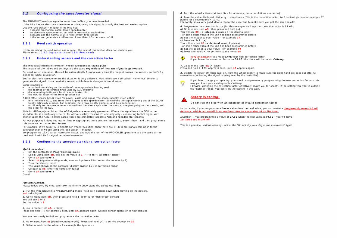
3.2 Configuring the speedometer signal The PRO-OILER needs a signal to know how far/fast you have travelled. If the bike has an electronic speedometer drive, using this signal is usually the best and easiest option. Use the reed switch + magnet if the bike has: • a classic mechanical cable-driven speedometer • an electronic speedometer, but with a mechanical cable-drive • does not use the normal 3-wire "Hall-effect" type sensor • if the sensor generates a difference of less than 1.5v between on/off. 3.2.1 Reed switch operation If you are using the reed switch and magnet, the rest of this section does not concern you. Please refer to 2.3.6 Signal source and 2.3.8 Reed switch 3.2.2 Understanding sensors and the correction factor
The PRO-OILER thinks in terms of "wheel revolutions per pump pulse". This means all the tables and settings are the same regardless of how the signal is generated. For reed switch operation, this will be automatically 1 signal every time the magnet passes the switch - so that's 1x signal per wheel revolution. But for electronic speedometers the situation is very different. Most bikes use a so-called "Hall-effect" sensor to generate the signal. It's a proximity sensor which detects changes in metal mass. Some examples: • a toothed metal ring on the inside of the output-shaft bearing seal • the toothed or perforated rings used by ABS systems • disc-mounting bolts on a fornt or rear brake rotor • the tips/flat faces of the front sprocket nut A Hall-effect sensor has 3 wires for power, earth and signal. The sensor usually wired either: • into the bike's ECU, and from there it goes to the speedometer. Sometimes the signal coming out of the ECU is
totally artificially created. For example, there may be 70x going in, and 9.4x coming out. • or, directly to the speedometer - sometimes the wire is split after the sensor, one part going to the speedo, and
the other to the ECU Note for ABS-equipped bikes: the ABS signals are separately generated. Where the signal from the ECU to the speedometer is articificially created, for obvious safety reasons it's one-way only - connecting to that signal wire cannot upset the ABS. In other cases, there are completely separate ABS and speedometer sensors. For our purposes it does not matter how many signals there are, we just need to count them, and then programme this value as our correction factor. For example, if we count 17.4 signals per wheel revolution, then there are 17.4x more signals coming in to the controller than if we are using the reed switch + magnet. We programme 17.40 as our correction factor, and now the rest of the PRO-OILER operations are the same as the reed switch with its 1x signal per wheel revolution. 3.2.3 Configuring the speedometer signal correction factor
Quick overview: • Set the controller in Programming mode • Select Menu Item oH, and set the value to 1 ("H" is for "Hall effect" sensor) • Go to oA and save it • Select ot (signal-counting mode, now each pulse will increment the counter by 1) • Turn the wheel x times • The value shown on the controller display divided by x is correction factor • Go back to oS, enter the correction factor • Go to oA and save it Done! Full instructions: Please follow step-by-step, and take the time to understand the safety warnings. 1. Put the PRO-OILER into Programming mode (hold both buttons down while turning on the power). oH is displayed. a) Go to menu item oH, then press and hold [-]("H" is for "Hall effect" sensor) You will see 0 or 1 Set the value to 1 b) Go to menu Item oA (= Save) Press and hold [-] for approx 6 secs, until oA appears again. Speedo sensor operation is now selected. You are now ready to find and programme the correction factor. 2. Go to menu item ot (signal-counting mode). Press and hold [-] to set the counter on 00 3. Select a mark on the wheel - for example the tyre valve
4. Turn the wheel x times (at least 5x - for accuracy, more revolutions are better)
5. Take the value displayed, divide by x wheel turns. This is the correction factor, to 2 decimal places (for example 87 pulses for 5 revolutions = 17.40) For safety, it's a very good idea to repeat the excercise to make sure you get the same result!
6. Programme the correction factor (for this example we'll say the correction factor is 17.40) a) Go to menu item oS , then press and hold [-] You will see 00. (= integer, 2 places + the decimal point) - or some other value if the unit has been programmed before b) Set the integer to your value - for example 17. c) Press and hold [-] You will now see 00 (= decimal value, 2 places) - or some other value if the unit has been programmed before d) Set the decimal to your value - for example 40 e) Press and hold [+] to get back to the menu oS
Very important: you must SAVE your final correction factor. If you leave the correction factor on 00.00, the there will be no oil delivery.
7. Go to menu Item oA (= Save) Press and hold [-] for approx 6 secs, until oA appears again. 8. Switch the power off, then back on. Turn the wheel briskly to make sure the right-hand dot goes out after 5x revolutions (indicating the signal is being read by the controller).
If you later change your gearing, you should compensate by programming the new correction factor - this way you keep your existing tables/settings. Likewise, changing the correction factor effectively allows you to "cheat". If the setting you want is outside the "normal" range, you can trick the system in this way.
Safety Warning: Do not run the bike with an incorrect or invalid correction factor!
In particular, if you programme a lower value than the real value, you can create a dangerously over-rich oil delivery, which can result in an accident due to excessive oil on the tyre. Example: If you programmed a value of 07.00 when the real value is 70.00 - you will have 10 times too much oil This is a genuine, serious warning - not of the "Do not dry your dog in the microwave" type!
3.3 Tables and settings 3.3.1 Explaining tables and settings
Several factors determine how much oil your chain needs and what settings you need. • Chain size, for example 530,525,520 • Length of chain, for example 106,110,114 links • Wheel circumference, for example 198cm for 180/55-17 or 187 for a 130/80-17 • Last, but not least, the pattern of aerodynamic turbulence around the rear sprocket Each bike model has different characteristics.
Generally speaking, the smaller and shorter the chain, the less oil it will need – no surprise there.
However, there are also differences between models with identical chain and tyre sizes – due to different patterns of aerodynamic turbulence.
There are 3 ways to get your initial base setting
• If you ordered direct from PRO-OILER, the recommended table will most likely already be pre-programmed, and if so, the table number is marked on the backing foil of the controller’s 3M DualLock.
• In practice, we know the typical consumption of most bikes on the market – look for yours in the Appendix: Typical tables/settings
• When a new one along, we can make a good guess based on known bikes with similar details. This guess is based on a formula, which you can find in the Appendix: Theoretical tables calculation.
To allow for the range of possible requirements from the smallest bike/chain to the largest, the PRO-OILER has 15 “tables”, and each table has 12 “settings”.
Each table’s 12 settings are arranged in a “curve” with a fixed shape – starting with small changes at the lean end, with changes becoming progressively larger at the rich end of the scale. See the chart below.
The difference between each table is its starting point – the “seed value”.
Starting at the richest table (6), the next table (7) is approx 5% leaner, and so on – you can see all the tables and their values in the Calibration and Standard mode Tables schedule below.
100 98 95 9288
8274
60
49
35
24
15
12/S50
20
40
60
80
100
120
1 2 3/S1 4/S2 5/S3 6 7 8 9/S4 10 11
Each table has the same shape
The chart on the left shows the % of the seed value distance (setting 1) between pump pulses.
Setting 1 is 100%, and setting 12 is 15% of that.
In other words, setting 12 is nearly 7x richer than setting 1 because it only needs 15% of the distance before the next pump pulse is triggered.
For fine tuning the oil delivery to your preferences, see 5.1 Finding the right setting Once you have the right table for your bike, then you can just select the settings within your table to adjust for your everyday needs (weather, dust etc)
Tables + settings:
The schedule below shows the tables in detail. This information is printed on the plastified card packed with the controller – it’s not a bad idea to leave this card under the seat, or somewhere accessible when you’re on the move.
The tables go from left to right, richest (6) to leanest (20).
Settings go from top to bottom, biggest distance between pump pulses to shortest distance.
The values are number of wheel revolutions per pump pulse.
“Calibration” and “Standard” modes are explained in 5. Using the PRO-OILER. Standard mode offers a restricted selection of the settings available in Calibration mode. Look at Standard mode like a sort of “quick mode”.
3.3.2 How to change the table • Turn off the power • Turn on the power while holding both [-/+] buttons down together
oH is displayed • Press [+] to select oC and then hold [-] for >2s
The currently selected table nr is displayed (for example 12) • Find the table you want with [-/+] • When done press [+] for >2s
oC displayed again • Press [+] repeatedly until oA is displayed • Press and hold [-] for approx 6 secs total
First SA is displayed (Saving) Then St in displayed (Save to EEPROM completed) When oA re-appears, switch off ignition - the changes are activated.
Note: to cancel the operation at any time before saving, just turn off the power.
4 Using the Pro-Oiler
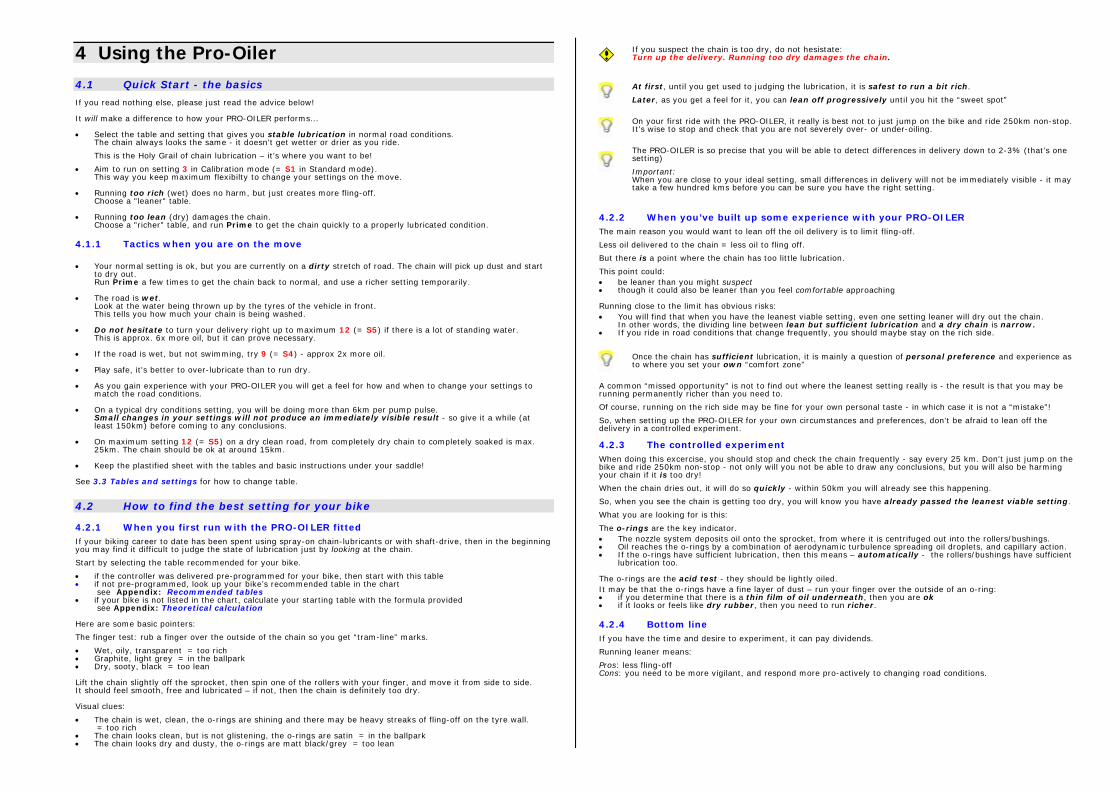
4.1 Quick Start - the basics If you read nothing else, please just read the advice below! It will make a difference to how your PRO-OILER performs... • Select the table and setting that gives you stable lubrication in normal road conditions.
The chain always looks the same - it doesn't get wetter or drier as you ride.
This is the Holy Grail of chain lubrication – it’s where you want to be!
• Aim to run on setting 3 in Calibration mode (= S1 in Standard mode). This way you keep maximum flexibilty to change your settings on the move.
• Running too rich (wet) does no harm, but just creates more fling-off.
Choose a "leaner" table. • Running too lean (dry) damages the chain.
Choose a "richer" table, and run Prime to get the chain quickly to a properly lubricated condition. 4.1.1 Tactics when you are on the move • Your normal setting is ok, but you are currently on a dirty stretch of road. The chain will pick up dust and start
to dry out. Run Prime a few times to get the chain back to normal, and use a richer setting temporarily.
• The road is wet.
Look at the water being thrown up by the tyres of the vehicle in front. This tells you how much your chain is being washed.
• Do not hesitate to turn your delivery right up to maximum 12 (= S5) if there is a lot of standing water.
This is approx. 6x more oil, but it can prove necessary. • If the road is wet, but not swimming, try 9 (= S4) - approx 2x more oil. • Play safe, it's better to over-lubricate than to run dry. • As you gain experience with your PRO-OILER you will get a feel for how and when to change your settings to
match the road conditions. • On a typical dry conditions setting, you will be doing more than 6km per pump pulse.
Small changes in your settings will not produce an immediately visible result - so give it a while (at least 150km) before coming to any conclusions.
• On maximum setting 12 (= S5) on a dry clean road, from completely dry chain to completely soaked is max.
25km. The chain should be ok at around 15km. • Keep the plastified sheet with the tables and basic instructions under your saddle! See 3.3 Tables and settings for how to change table.
4.2 How to find the best setting for your bike 4.2.1 When you first run with the PRO-OILER fitted If your biking career to date has been spent using spray-on chain-lubricants or with shaft-drive, then in the beginning you may find it difficult to judge the state of lubrication just by looking at the chain.
Start by selecting the table recommended for your bike.
• if the controller was delivered pre-programmed for your bike, then start with this table • if not pre-programmed, look up your bike’s recommended table in the chart
see Appendix: Recommended tables • if your bike is not listed in the chart, calculate your starting table with the formula provided
see Appendix: Theoretical calculation Here are some basic pointers:
The finger test: rub a finger over the outside of the chain so you get “tram-line” marks.
• Wet, oily, transparent = too rich • Graphite, light grey = in the ballpark • Dry, sooty, black = too lean Lift the chain slightly off the sprocket, then spin one of the rollers with your finger, and move it from side to side. It should feel smooth, free and lubricated – if not, then the chain is definitely too dry. Visual clues:
• The chain is wet, clean, the o-rings are shining and there may be heavy streaks of fling-off on the tyre wall. = too rich
• The chain looks clean, but is not glistening, the o-rings are satin = in the ballpark • The chain looks dry and dusty, the o-rings are matt black/grey = too lean
If you suspect the chain is too dry, do not hesistate: Turn up the delivery. Running too dry damages the chain.
At first, until you get used to judging the lubrication, it is safest to run a bit rich.
Later, as you get a feel for it, you can lean off progressively until you hit the “sweet spot”
On your first ride with the PRO-OILER, it really is best not to just jump on the bike and ride 250km non-stop. It’s wise to stop and check that you are not severely over- or under-oiling.
The PRO-OILER is so precise that you will be able to detect differences in delivery down to 2-3% (that’s one setting)
Important: When you are close to your ideal setting, small differences in delivery will not be immediately visible - it may take a few hundred kms before you can be sure you have the right setting.
4.2.2 When you’ve built up some experience with your PRO-OILER The main reason you would want to lean off the oil delivery is to limit fling-off.
Less oil delivered to the chain = less oil to fling off.
But there is a point where the chain has too little lubrication.
This point could: • be leaner than you might suspect • though it could also be leaner than you feel comfortable approaching Running close to the limit has obvious risks: • You will find that when you have the leanest viable setting, even one setting leaner will dry out the chain.
In other words, the dividing line between lean but sufficient lubrication and a dry chain is narrow. • If you ride in road conditions that change frequently, you should maybe stay on the rich side.
Once the chain has sufficient lubrication, it is mainly a question of personal preference and experience as to where you set your own “comfort zone”
A common “missed opportunity” is not to find out where the leanest setting really is - the result is that you may be running permanently richer than you need to.
Of course, running on the rich side may be fine for your own personal taste - in which case it is not a “mistake”!
So, when setting up the PRO-OILER for your own circumstances and preferences, don't be afraid to lean off the delivery in a controlled experiment.
4.2.3 The controlled experiment When doing this excercise, you should stop and check the chain frequently - say every 25 km. Don't just jump on the bike and ride 250km non-stop - not only will you not be able to draw any conclusions, but you will also be harming your chain if it is too dry!
When the chain dries out, it will do so quickly - within 50km you will already see this happening.
So, when you see the chain is getting too dry, you will know you have already passed the leanest viable setting.
What you are looking for is this:
The o-rings are the key indicator. • The nozzle system deposits oil onto the sprocket, from where it is centrifuged out into the rollers/bushings. • Oil reaches the o-rings by a combination of aerodynamic turbulence spreading oil droplets, and capillary action. • If the o-rings have sufficient lubrication, then this means – automatically - the rollers/bushings have sufficient
lubrication too. The o-rings are the acid test - they should be lightly oiled. It may be that the o-rings have a fine layer of dust – run your finger over the outside of an o-ring: • if you determine that there is a thin film of oil underneath, then you are ok • if it looks or feels like dry rubber, then you need to run richer. 4.2.4 Bottom line If you have the time and desire to experiment, it can pay dividends.
Running leaner means:
Pros: less fling-off Cons: you need to be more vigilant, and respond more pro-actively to changing road conditions.
4.3 Tactics in daily use
The PRO-OILER is pretty much fit-and-forget, but you do get the best results if you put a little thought into how you respond to changing road conditions
Example 1.
It’s started to rain - turn the oil delivery up straight away.
How wet is wet?
- damp, dirty, but not much standing water: try settings 5 or 6 - it’s wet, some standing water, some spray coming off the vehicle in front: try 7 to 10 - full wet conditions, plenty of standing water: don’t hesitate, go for 12 Turn down the delivery when/as road conditions improve. Example 2.
It just rained, you turned up the delivery, and now the roads are dry again - but you forgot to turn down the delivery back to 3 or S1
The chain is now too wet. This is just a temporary situation, so you could reduce the delivery to 1 or 2 for a while.
Q: Why not simply turn it off (--)?
A: You could turn it off, but the risk is you may not "time" your return to the normal setting 3 correctly, and you could run dry. This is as just likely to happen as forgetting to turn the delivery back down after the rain!
At least on setting 1 or 2, the chain's condition will stabilize steadily.
Example 3.
You see the roads are getting dusty or dirty and the dirt is sticking to the chain, drying it out. Now you have a choice
You could turn up the delivery a bit to 4 or 5 (= S2 or S3) and see if this does the job.
But if these conditions are going to go on for some time (let's say it's a seasonal problem, or you’re riding dusty mountain roads), then you could move to a richer table, and then go back to setting 3.
Example 4.
You have just ridden along an unmade dusty road, and the dust has stuck to the chain, drying it out. Again you have a choice:
The obvious one is to run Prime a few times, and leave the settings as they are.
But, you could turn up the delivery to max for a short while - or both (don't forget to turn the delivery back down!)
Example 5.
You've just washed the bike with a power hose, (of course you wouldn't clean the chain like that, would you?) so you want to give the chain a quick shot. Run Prime a couple of times while on the move.
4.4 Modes The PRO-OILER has 3 "Modes" - Calibration, Standard and Emergency.
Calibration Mode is the "normal" mode for those wanting full detailed control over their settings (12 settings - 1..12)
Standard Mode is limited to 5 settings (S1..S5) which are a subset of Calibration Mode settings.
Think of it as “quick” mode.
Standard mode S1 is the same as 3 in Calibration mode
S2 = 4, S3 = 5, S4 = 9, S5 = 12
In Calibration and Standard modes you select your setting based on the distance traveled between pump strokes. These are the normal modes.
Q. Why have the two modes? A. Standard mode has just 5 settings and is a bit quicker/easier to operate - but you have less fine control over your
settings - the choice is yours! See 3.3 Tables and settings Emergency Mode is used in case of no signal from the reed switch, lost magnet, disconnected reed switch or speedo sensor - or for use off-road where distance travelled is not an issue.
In Emergency mode you select your setting based on the time interval between pump strokes.
This allows lubrication even when there is no signal. You can switch to this mode when on a trip and you lose the signal. Emergency mode has 19 settings from E1..E9, 1E..9E, EE
See Appendix: Emergency mode
4.4.1 How to change modes Press and hold [-] for >5s to toggle change to the next mode.
The system cycles between the 3 modes: Standard > Calibration > Emergency > Standard...
You can also toggle directly between Calibration/Standard Mode and Emergency Mode - press both buttons together.
4.5 Operating mode: information, warnings and functions 4.5.1 Warnings + system information The right-hand decimal point: This comes on when no signal has been received from the reed switch/speedo sensor for 2 secs (normally when you come to a stop).
It should go out when you set off again after 5 wheel revolutions.
If it the right-hand decimal point stays on while riding, the means: There is no signal from the reed switch /speedo sensor Switch over to Emergency mode (timed mode which takes no account of incoming signals)
The left-hand decimal point: This only comes on when the pump pulses - it's a 2 second flash which you will not normally notice!
Do not ride along watching the display for the pump pulse light to come on – that’s a serious distraction!
Depending on your setting, that could be 6-10km riding while watching for a 2 second flash.
If you wish to check the pump pulse count, use the built pump pulse counter function.
4.5.2 How to see your current settings Turn on the ignition, and the following info is displayed in sequence - Pro-Oiler message - Main version nr (eg 02) - Sub version nr (eg 09) - Currently selected Correction Factor - only the integer part (eg 00 or 17) - Currently selected table (eg 09) - Display ends up on current setting (eg 3. or S1. - or E6 if you are in Emergency mode) Note: the Main + Sub version numbers are needed when contacting PRO-OILER with calibration or settings questions 4.5.3 How to activate Prime Press [+] for >2s The Prime cycle will run 20 pump pulses, which you see flashing up on the display. There is no need to hold the button down once the Prime cyle has started.
To check that the pump is actually pumping, place a finger on the pump - you should feel (and maybe also hear) a light tapping.
Note: the Prime cycle increments the pump pulse counter by 20. See the FAQ for more information on Prime 4.5.4 How to toggle the display on/off: You may wish to set display off at night.
Press [-] for >2s to toggle the display on/off.
The display will show do when “display=on”, and then return to showing your currently selected setting.
Note: the left and right hand decimal points come on whether the display is on or off
5 Maintenance
5.1 System maintenance The PRO-OILER system itself needs no scheduled maintenance. Maintenance is limited to visually checking from time to time that: • the nozzle system is undamaged and correctly aligned • the oil lines are securely in place, and not being chafed or crushed • the breather is not blocked Keep an eye on the the oil level, and refill the container when required.
It is best not to wait until the container is almost empty.
As the oil sloshes around with the bike’s acceleration and braking, the chance of the pump drawing air instead of oil increases.
5.2 Chain maintenance If you are used to cleaning your chain and then lubricating it with spray-on grease on a regular (or irregular!) basis, life with a PRO-OILER will come as a big surprise.
You don’t actually need to do anything any more!
Simply look at the chain from time to time, say at fuel stops.
As you become familiar with the PRO-OILER’s behaviour, you will know how the chain is supposed to look when the PRO-OILER is adjusted according to your preferences, and everything is working as it should be.
If you find the chain is unexpectedly dry or wet, then consider whether: • road conditions have changed, and you should maybe adjust your setting • the oil level is low • there may be a problem with the nozzle system, or other part of the PRO-OILER system.
See Troubleshooting for more information 5.2.1 Some general maintenance tips If your preference is to run on the rich side
When using oil (instead of tacky spray-on grease), the chain is self-cleaning; that is to say, the oil flings off taking the dirt particles with it.
The richer your general setting, the more pronounced the self-cleaning effect, and there comes a point where the chain always looks clean, shiny and new.
For many PRO-OILER owners, this is the perfect scenario – the only downside is a bit more fling-off.
The fling-off is just oil, not a sticky gunge as with spray-on lubricants, so it is easy to clean off.
To remove fling-off, you can: • wash the surfaces with standard detergent products suitable for automotive use • spray the surfaces with WD40 or similar, then wipe off with a paper towel or rag • spray WD40 onto a paper towel or rag, then wipe the surfaces clean • or of course, whatever favourite method you have developed… If your preference is to run on the lean side
You can also run the PRO-OILER using leaner settings, where the chain’s rollers/bushings are fully lubricated, and the o-rings have enough coverage, but where the quantity of oil coming onto the chain is not sufficient to wash it in oil, and so the outside chain plates can dry out and collect a thin layer of dust.
There will still be some fling-off - what goes onto the chain also comes off it, but just less of it.
Remove the fling-off simply using one of the techniques mentioned above.
But in addition, you may wish to wipe down the chain itself: Spray WD40 or similar onto a paper towel or rag. This takes just one or two passes of the chain – no rubbing is needed, just wipe.
Never wipe the chain down with the bike on a stand and the engine running in gear. This is just as (or maybe even more) likely to remove your fingers as being careless with a chainsaw or circular saw.
Anti-corrosion tips Oil is not tacky like chain-grease, so it can eventually wash off when left standing out in the rain. If you will be leaving the bike out in wet conditions, you could do one of the following quick fixes: • Crank up the oil delivery for a while before you reach your destination, either by selecting setting 12/S5, or by
running prime a few times to soak the chain. • Wipe the chain with a well-oiled rag But there is another type of solution: Apply a dedicated anti-corrosion oil to the chain.
There are many anti-corrosion products on the market, each with their pro’s and con’s – and some of these may be suitable for use on an o-ring chain – but others may attack the o-rings.
One product we know for certain is highly effective and guaranteed harmless is ACF-50 from Lear Chemicals – do an Internet search to find out how it works.
We ourselves, and a number of our customers, have tested ACF-50 with success – and in fact we have several bikes running with 10% ACF-50 mixed into the lubricating oil.
Important: ACF-50 is 100% compatible with both the chain’s o-rings and the pump’s seals
Appendix
Theoretical tables calculation
Important! This is just a safe, conservative (=rich) starting point You will probably need to select a leaner table – on some bikes maybe even several tables richer .
To do the base calculation, you need the following information: • Chain size • Chain length (number of links) • Tyre size for the wheel with the speed sensor or reed switch • And you'll need a pocket calculator... As a point of reference, we'll take a typical big-bike setup (eg. Bandit 1200) • Chain size 530 • Chain length 110 • Tyre size 180/55-17 This is index 1.00 Step 1 Chain size:
• If you have a 530 - enter 1 in your calculator • If you have a 525 - enter 1.4 in your calculator • If you have a 520 - enter 1.65 in your calculator Step 2 Chain length:
Take the result from Step 1
• Multiply by 110 • Divide by your chain length Step 3 Tyre circumference: Take the result from Step 2 Multiply by 198 Divide by the tyre size of the wheel where the reed switch is fitted 198 = 180/55-17 196 = 160/60-17 192 = 150/60-17 187 = 130/80-17 187 = 90/90-17 188 = 120/70-17 181 = 120/60-17 The formula to calculate the nominal tyre circumference in cm is: ((wheel dia x 2.54) + (tyre section/10 x tyre height% x 2)) x 3.142 Example: Size 180/55-17 ((17 x 2.54) + (18.0 x 0.55 x 2)) x 3.142 = (43.18 + 19.8) x 3.142 = 198 Note: this gives the nominal circumference - in real life, factors such as tread wear, actual wheel width and even tyre manufacturer can lead to a few % difference either way. To know for sure, use the classic method of marking the tyre with chalk, move the bike so the wheel does one revolution, and measure the distance on the ground. Step 4 Multiply the result of Step 3 by the constant: 2800 Now look at the tables and find the seed value (= Setting 1) with the value closest to your result. Select the table to the left (richer) - this is the one to use as your starting point. Example:
Your bike has a 525 chain, 108 links and a 160/60-17 rear tyre. You would enter:
1.4 x 110 ÷ 108 x 198 ÷ 196 x 2800 = 4033 = Table 15 (being the closest table with a seed value below of 4033) So, now select table 15. See 3.3.2 How to change table Finally, select setting 3 (or S1 if you want Standard mode) See 4.2 How to find the best setting for your bike for fine tuning your selection
Emergency mode Emergency Mode works on time interval between pump strokes.
Emergency Mode is so-called because you would use this if you have a reed switch or speedo signal problem, and there's no incoming signal. Emergency mode allows you to continue lubrication - the clock is running as long as the PRO-OILER is powered ON.