The seventeenth ordinary general meeting of the South African Institute of Electrical Engineers was held in the Lecture Theatre of the South African School of Mines, Johannesburg, on Thursday, the 27th July, 1911, at 8 p.m., Mr. J. H. Rider (President), in the chair. There were present:—14 members : Messrs. J. W. Kirkland, B. Price, E. W. Bentley, A. E. Gibbs, F. H. Michell, W. H. Per row (Members of Council), E. S. Curtis, W. F. Cosser, A. M. L. Danirarich, R. C. Hickling, C. McCann, A. B. Nicholetta, W. Sutton, P. M. Tennick. 11 Associate Members: Messrs. G. H. B. Bernard, E. V. Perrow (Members of Council), A. N. Aikinan, "W. M. Bowman, R. B. Can ning, R. W. Kemble, D. S. Kinsey, A. S. Neil son, A. E. Scott, J. W. Westwood, T. F. Whimster, 9Associates and Students: Messrs. G. J. Absalom, S. L. Hangei'-Bain, A. Cooper, E. M. Dall, I. Glasser, A. L. Lipman, H. Perks, E. Read, T. Stanley. 10Visitors, and Fred Rowland, Secretary. Minutes. The minutes of the sixteenth ordinary general meeting, as piloted in the May Transactions, were confirmed. Membebship. Messrs. R. B. Canning and A. E. Scott were appointed scrutineers, and after their scrutiny of the ballot papers, the President announced that all the candidates for membership had been elected as follows ;— As a Member: Ewinu, Sydney EnwAim Tracker, Brakpan Mines, Ltd., P.O. Box3, Brakpan, Chief Electrical Engineer, PROCEEDINGS AT SEVENTEENTH ORDINARY GENERAL MEETING. July 27th, .1911.
Transcript
The seventeenth ordinary general meeting of the SouthAfrican Institute of Electrical Engineers was held in the LectureTheatre of the South African School of Mines, Johannesburg, onThursday, the 27th July, 1911, at 8 p.m., Mr. J. H. Rider(President), in the chair.
There were present:—14 members : Messrs. J. W. Kirkland,B. Price, E. W. Bentley, A. E. Gibbs, F. H. Michell, W. H. Per row(Members of Council), E. S. Curtis, W. F. Cosser, A. M. L.Danirarich, R. C. Hickling, C. McCann, A. B. Nicholetta, W.Sutton, P. M. Tennick.
11 Associate Members: Messrs. G. H. B. Bernard, E. V. Perrow(Members of Council), A. N. Aikinan, "W. M. Bowman, R. B. Canning, R. W. Kemble, D. S. Kinsey, A. S. Neil son, A. E. Scott,J. W. Westwood, T. F. Whimster,
9Associates and Students: Messrs. G. J. Absalom, S. L.Hangei'-Bain, A. Cooper, E. M. Dall, I. Glasser, A. L. Lipman,H. Perks, E. Read, T. Stanley.
10Visitors, and Fred Rowland, Secretary.
Minutes.
The minutes of the sixteenth ordinary general meeting, aspiloted in the May Transactions, were confirmed.
Membebship.Messrs. R. B. Canning and A. E. Scott were appointed
scrutineers, and after their scrutiny of the ballot papers, thePresident announced that all the candidates for membershiphad been elected as follows ;—
Baumann, Maximilian Otto, S.A. School of Mines and Technology,P.O. Box 1176, Johannesburg. Student.
Beerstecher. Leonard, S.A. School of Mines and Technology, P.O.Box 1176, Johannesburg. Student.
Chaplin, Cyril Julian, S.A. School of Mines and Technology, P.O.Box 1176, Johannesburg. Student.
Dedlow, Carl, S.A. School of Mines and Technology, P.O. Box 1176,Johannesburg. Student.
Getz, David, S.A. School of Mines and Technology, P.O. Box 238,Roodepoort. Student.
Issels, Henry George, S.A. School of Mines and Technology, P.O.Box 1176. Johannesburg. Student.
Jensen. Axel Em.il, S.A. School of Mines and Technology, P.O. Box1176, Johannesburg. Student.
Lipman, Abraham L., S.A. School of Mines and Technology, P.O.Box 1176, Johannesburg. Student.
Rose. Victor, S.A. School of Mines and Technology, P.O. Box 1176,Johannesburg. Apprentice.
Smith, Herbert Oscar, S.A. School of Mines and Technology, P.O.Box 1176, Johannesburg. Student.
Thornton, Arthur Cecil, S.A. School of Mines and Technology,P.O. Box 1176, Johannesburg. Student.
BEPLY TO DISCUSSION.
Mr. Chas. McCann: In replying to the discussion on mypaper I am faced with one great, difficulty, that is, that no practicaldiscussion has taken place which I can reply to. There have been,however, a few questions asked which I will endeavour to answer.On page 21 I^ of the Journal, our President asks me to enlarge onmy reference to the "interval between blasting and men returningto work." At present the poisonous gases are blown out of theworkings after blasting by theregular ventilation system of the mine,assisted by a number of cocks left open on the compressed air system,but the amount of air available on the air system is decided by thecapacity of the existing compressors. In my proposition all thenumerous divisions or stages of the turbo-compressors would beput in parallel (instead of in series as when high pressures arerequired), thus delivering to the mains say 8 to 10 times thenormal amount of air, but at a low pressure and temperature.This being the case, it is obvious that the workings will be blownout very much faster, say at least in one-fourth of the time nowrequired. The number of minutes required will of course varyunder different conditions. With reference to the cost of reheatersnoted on the same page, I gave those prices as being roughly themaximum and minimum total costs installed, covering the usualsomewhat wide range of local conditions. The reheater that I madefor experimental purposes consisted of a chamber 4 feet long and2 feet square. In this were placed cast iron resistance grids ofthe usual well-known type supplied for electric rheostats. Thesewere arranged as baffle plates in such a manner that practicallyevery atom of air came in contact with them, but the back pressuredid not exceed ^ lb. The grids were kept at a dull red heat andthe air was raised from about 80 F. to I think 220 F. Thedevice was inserted in a 4 inch diameter air main supplying airto a winch and two pumps. This was done many years ago, andI regret I cannot remember the actual results, but the experiment,crude though it was, was a decided success. But, as I say in mypaper, if we run electric mains to a machine, why not instal amotor instead of a heater. I think it is an open secret that anelectric percussion drill is now being successfully developed at
By Oh AS. McCANN {Member).
[Head al October Meeting),
ELECTRICALLY-DRIVEN AIR COMPRESSORS.
July, 1911.Electricall^ Driven Air Compressors,127
I2f>' lilettlrkatiy Driven Air Cijtiipresnork.July, 11)11.
home, and will shortly be on the local market. We will then wantair for nothing but ventilation, and even then I feel sure that theunderground motor-driven turbo-propellor will be found the hest_
On page 389 of the Journal^ Mr. Newbery asks me how Iwould govern the compressors which I described ? As the compressors would be direct coupled to 3-phase motors, we may takeit that the speed would be practically constant, and I supposegoverning would be accomplished by automatically throttling theinlet. Perhaps some of our members, who are connected withthe new power schemes, can tell us how this is accomplishedat Rosherville and Robinson. Mr. Newbery has misunderstoodme about the number of compressors to be installed. Idid not suggest one for each drill, but one for each 10drills, and in the paper I mentioned, on page 293, that the airwould be drawn from the surface through a pipe, if the air in theshaft was not suitable. The water to be used for cooling purposesmust be mine water of course and must be purified : the cost ofthis would be small in comparison with the total saviug realised bythe adoption of the complete scheme.
With regard to the remarks made by Mr. Kirkland and Mr.hllsdon Dew, on page 7 (1911), re booster compressors, I did nottouch on this matter as I understood that we were to have a paperdevoted exclusively to them. At the same time I hoped that someinformation abont them would be brought out in the discussion.1 hope at some future date those of our members who have beenexperimenting with them will give us the benefit of their experiences. The President remarks on the same page that "it wouldhe interesting to have figures of the relative costs of drivingordinary reciprocating compressors by motor and steam engines."I have given these figures on page 290 for a 100 drill plant. Anannual saving of over ti,000 can be obtained by disconnectingthe steam ends and installing a motor to drive on to the flywheel.On a new job the saving is over 9,000 per annum.
These few remarks I think dispose of the questions that havebeen put to me at our meetings. There are however a number ofquestions that have been put to me in other places, and manyinteresting, but unfortunately private, discussions have taken place.Many engineers have questioned my item of 10,000 for a 30 drillsteam driven compressor, but I can assure them that this figure iscorrect, being taken from an actual plant recently installed here.The items were as follows :—compressor, 4,000 ; erection, 350;building, 050 ; condensing plant (erected), 1,200 ; cooling plant
. and tower (erected), 1,200 ; air receiver, 100 ; three 100 H.P.boilers, 1,200 ; erection, 350 ; building, 400 ; piping, pumps,and sundries, 150; stack, 400; economiser, 300 ; total
10,500. But if three units instead of one were installed the
,500 might be discarded owing to the saving on the buildings andsome other items. The estimate for the motor-driven compressoris noil takeh :tfrom work done but from tenders recently receivedby one of our leading mining houses. The items are ;—compressor
3,000; erection, 300; building, 600: air receiver, 100;motor and control gear, 1,000 ; total, -1,000. Engineering feesand contingencies are not included in either case, but as they areusually taken as percentage of capital outlay they would onlyimprove an already good case made out for electrification.
Another point which has raised much discussion, especiallyamong our purely* inecha^iieal friends, is my* figure of adifference in favohr of electrical power as compared with steamof 0"3d. per hour. This was arrived at in this way. I obtainedfifteen different sets of figures from fifteen different mines, givingthe cost'of-steam power. These sets of figures embraced cost ofcoal and water, oil, wages (not including engine driver's wages,as he is required to attend to the compressor, no matter how it isdriven), capital charges, etc., and average 0'7d. per hour ;•03d. per hour is added on page 292 for engine room wages andsupervision, making the total working costs for steam, -73d.I understand the power supply companies are willing to supplypower for a demand of this description at a cost of 0'4d. per H.P.hour giving, as I stated,,0"3d. difference in favour of electric driving.I have added on page 292 the "03d. for wages and supervision,and a further -07d. on account of possible, but not probable,additional contingencies connected with electric driving, makingthe working cost up to (had. as against ()'73d.
In concluding these few remarks, I wish to express mydisappointment at-the reception accorded to my paper. That thepaper was incomplete I know, that it ought to have produced avoluminous and interesting discussion I also know, It is mostdisheartening to spend a lot of time and put in a lot of workpreparing a paper which only a few (and they from a sense ofduty, probably) take the trouble to make any comments on.I will take the liberty to point out to you all that the study ofcompressed air is as necessary to your successful future inconnection with mining as is the study* of electricity.
July, 1911,,Electrically Driven Air Compre^sors.
Discussion.Mr. T. F. Whimster (Associate Member) : I do not think that
this paper lends itself very readily to criticism or discussion. Thefirst part of the paper was a description of the Kelvin balance,which, of course, one cannot very well criticise. At the sametime, I think there are some points in the second part of thepaper upon which one might pass some legitimate criticism, andsome points also which might be expected to raise considerablediscussion. For instance, there is the question whether it iswise to use current transformers of low KW. capacity for obtainingheavy currents. Indeed, unless one knows that the current obtainedfrom such an arrangement is one of sine wave form, it is unwiseto use current transformers to obtain heavy currents. I haveknown instances where ordinary instrument current transformershave been used by supplying the secondary with small current,and obtaining from the primary heavy current. I think that ifthe people who use such an arrangement for calibrating wereto see the wave form of the current they were obtaining theywould be surprised, and perhaps decide that it does not always payin A.C. work to take the easiest method of obtaining heavycurrents, and be more careful next time. Even when a currenttransformer is specified to give a current of sine wave form,if it is overloaded at all a quite different wave form willbe obtained, and a point to be noticed in using such anarrangement especially in calibrating work, is that you getdifferent results depending on the inductance in the testingcircuit. In calibrating instruments or meters, it is not safe whenusing a current transformer of low KW. capacity, unless you knowthat you have a sine wave form, to make the calibrations at all.Eor these reasons I think it is far preferable to get a heavy currentalternator and incidentally obtain better adjustment.
Speaking generally of the Kelvin Balance, I am inclined tothink that in the field of D.O. work, the Kelvin Balance has beensuperseded by other standard instruments, and I believe that nowit has been surpassed in the field of A.C. work as a standardinstrument. I believe for accuracy of measurement and width ofrange a D.O. potentiometer is a much more valuable instrument
By F. H. MiCHErm, A.M.I.E.F. (Member of Council,).
(Read at December Meeting.)
THE MEASUREMENTS OF LARGE ALTERNATINGCURRENT E.M.F.'S AND POWER BY
THE KELVIN BALANCE.
130Measurements of Large A.C. E.M.F's and Power. July, 1911.
than the Kelvin Balance, and on the other hand there has recentlybeen introduced on the market an A.C. potentiometer, which isan ingenious adaptation of the D.C. potentiometer to A.C work,invented and designed by Dr. Drysdale and made by Tinsley & Co.,London. This instrument has been supplied to several firms. Itcan be used for A.C. or D.O. work alike, and with it it is possibleto measure l/100,000th of a volt. It can thus be seen how usefulan instrument it becomes used in conjunction with standardshunts. Currents can be measured with extreme accuracy toalmost any magnitude.
Another point which the author mentions, I think, is the useof the instrument commercially, but it is not possible to adjustthe Kelvin Balance on varying loads. What I mean is that ifyou have a varying load it is difficult to adjust a sliding weight ona scale to obtain a balance with any degree of accuracy. Anotherpoint to be gained over the Kelvin Balance by the A.C.potentiometer is that one can, when measuring KWs., read directfrom a dial the power factor, which is a very great advantage. Ishould like to know what the author thinks about the testing ofinstruments or meters in position. I think that is what he refersto when he mentions the possibility of the Kelvin Balance beingused in this sphere of commercial work, but I should liketo know how he is going to insert a Kelvin Balance for onething, and when inserted how he is going to obtain accurateresults. I do not think that the A.C. potentiometer until now,at any rate, is suitable for use in that connection either,but no doubt it will be before long. In connection with D.C.work in conjunction with a uni-pivot galvanometer, the D.C.potentiometer is capable of extreme accuracy and convenience inthe outside testing work, and I do not think it will be long beforethe A.C. potentiometer will be useful for that also. I thinkthat taking everything into consideration—the accuracy of resultsto be obtained and the convenience with which the work can bedone without interruption to supply—the very best method inthe calibration of instruments where current transformers areused is to calibrate the gear complete (meter or instrument) withits current transformers in the laboratory^ and at the same timeinsert a check meter and keep the results both of the standard andof the KW. measured by the check meter inserted in the secondaryin series with the wattmeter under test. Then if the wattmeter isinstalled one can take the check meter and insert it and getexcellent results, unless anything goes wrong with the current orpressure transformer, in which case most probably the effect of abreakdown on a current transformer or pressure transformer wouldbe so pronounced that one would know that there was somethingwrong. So I do not think it is necessary in position to insert aprimary instrument,
July, 1911. Measurements of Large A.C. E.M.F's and Power.'131
Discussion.Mr. W. C. Brown (Member of Council) -. I would like to
add my thanks to those already expressed to Mr. Bernard forpresenting such an important subject as switchgear.
To my mind a modern station can be divided into threesections, viz., the engines and boilers, generators and Switchgear.Of these sections, it would be difficult to state which is of thegreatest importance. I think if I were asked, I would say theswitchgear. However good the rest of the plant may be, it willbe almost useless if the switches are faulty, and looking at thegear that we depend on for the handling of high tension currents,does it not strike one that our present apparatus and designs arefar from perfect.
It has been said that the greatest progress made in recentyears in electrical engineering is in the switchgear. Possibly thatis so, but still there seems to be plenty of room for furtherimprovement.
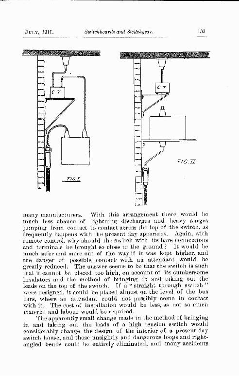
I believe, if low tension currents had never existed, the hightension switchgear seen to-day in some of the largest and mostmodern stations would be quite different, and the reason for thiscan be easily found. Modern high tension switches are merelylow tension designs adapted for high tension currents by theaddition of extra large insulating bushings and. larger oil tanks.There is nothing original in the design, and no efforts appear tohave been made to overcome or prevent damage caused by heavysurges. A glance at Fig. 1 will serve to illustrate my meaning.
This shows a low tension current transformer and a modernlow cension oil switch. Both of these types are in common use,and the general arrangement is a common, but not very good one,yet almost the identical arrangement and design of current transformer and switch is seen in use for the control of extra hightension currents. This does not seem to be quite right, and existssolely on account of the design of the switch and current transformer. A much better arrangement would be as shown inFig. 2. This may be considered as either vertical or horizontal.
There seems to be no reason why such a " straight through "switch should not be designed to work quite successfully, and"straight through" current transformers can be obtained from
SWITCHBOARDS AND SW1TCHGEAR.By G. H. B. BERNARD (Associate Member of Council).
(Read at May Meeting).
132Switchboards and Switchyear,JliMF, 1911.
many manufacturers. With this arrangement there would he.much less chance of lightning discharges and heavy surgesjumping from contact to contact across the top of the switch, asfrequently happens with the present day apparatus. Again, withremote control, why should the switch with its bare connectionsand terminals be brought so close to the ground ? It would bemuch safer ami more out of the way if it was kept higher, andthe danger of possible contact- with an attendant would begreatly reduced. The answer seems to be that the switch is suchthat it cannot be placed too high, on account of its cumbersomeinsulators and the method of bringing in and taking out the.leads on the top of the switch. If a "straight through switch "were designed, it could be placed almost on the level of the busbars, where an attendant could not possibly come in contactwith it. The cost of installation would be less, as not so muchmaterial and labour would be required.
The apparently small change made in the method of bringingin and taking out the leads of a high tension switch wouldconsiderably change the design of the interior of a present dayswitch house, and those unsightly and dangerous loops and right-angled bends could be entirely eliminated, and many accidents
Switchboards and Sioitchgear-July, 1911.
and breakdowns averted. The same argument of course appliesto low tension gear.
I should like to ask the author why nearly all oil switcheshave iron lids bushed with porcelain, instead of having the lidsmade entirely of porcelain. I should think that porcelain lidscould be made sufficiently strong for that purpose. Several caseshave come to my notice of the solder in the cable sockets becomingsoft and running (owing to bad contacts), and short circuiting orbadly earthing the leads on the top of the switch case. Thiscould not have occurred had the tops been made entirely ofporcelain.
Another complaint that I have against the present day oilswitch is, that the rods that connect the cable sockets to thecontacts are usually round, instead of being square where theypass' through the porcelain bushings ; consequently, whentightening up the nuts the contact stud is apt to turn, and twistthe contacts to such an extent that the switch cannot be operated,or, if the switch can be put in, the contact is so bad that troubleis very likely to follow.
As regards the rated capacity of low tension oil switches,I find it a safe rule to divide the manufacturers' rating by T5,and the contacts of enclosed fuses by 2. I do not blame themanufacturers so much for this, as the most unreasonable demandthat exists for low-priced apparatus and the competition causedthereby. My experience is that cheap apparatus proves itself tobe the most expensive.
I have been troubled with switches not tripping out whenthe plunger in the solenoid operates. This I have found to bedue mainly to dust and dirt that settles in the toggles, etc., andI consider for satisfactory service all trip gear should be totallyenclosed in dustproof cases.
I have often felt the want (at a reasonable cost) of a reliableswitch and protection gear for starting 20 h.p. (and under)squirrel cage motors straight on to the mains. Many makeshiftsexist, such as throw-over switches, etc., but they are not verysatisfactory, and the contacts gave considerable trouble.
Most manufacturers endeavour to make a quick break oilswitch, but very few make a hand operated oil switch with aquick " make." Can Mr. Bernard tell why this is ? In theordinary type of oil switch, I have found that the contacts (owingoften to the heavy starting currents) get burned and damaged farmore when switching on than in switching off, yet manufacturersstill ignore the fact that a quick and positive " make " is offar greater importance.
Among other details in connection with switchgear, thereseems to be room for a combined high and low tension switchfor transformers ; not necessarily a high and low tension switch in
134Switchboard^ and Switchgear.July, 1911.
the same oil tank, hut a switch, or pair of switches, mechanicallyconnected together so that they can be operated by one handle.Several accidents have occurred to men who have been sent torepair or examine a high tension switch, who have switched offthe high tension side, but have forgotten or did not think itnecessary to also switch off the low tension side, and have inconsequence run into what might have been serious trouble.
Mr. H. E. Zurich (Associate) • There are a few questions Iwould like to ask Mr. Bernard in connection with his veryinteresting paper.
We have in Ali wal North a three wire direct current system, andthe great trouble which we have experienced is the balancing ofthe load on the feeders. One night the overload is on the positiveside, and the next night the overload may be on the negative side.We have found it impossible to balance the load between the outerconductors. The balancer at the station can supply up to 21 amps.,but at times this is quite insufficient. In the balancer circuit at thestation there is no fuse or circuit breaker to prevent the armaturefrom burning out, either from a short circuit or from a groundoccurring on the distribution cables. This I think is bad,and I should like to know if it is possible, or necessary, to put inthe circuit some sort of a safety device to protect the armature.The connections are direct to the bus bars, through a main doublepole throw-over switch, shunt regulator and starter in series withthe armature. When a ground occurs, the pressure rises abovethe normal pressure very much, and if the attendant is not smart,the insulation of armature of the balancer will break down, sincethe cut-out of dynamos sometimes stick.
Our switchboard consists of marble slabs mounted on an ironframework, with all the recording instruments mounted directlyupon it. It is very compact, and all switches are close toone another. This we have found very convenient when shuttingdown the plant due to a fault either in the station or on one ofthe feeders. As regards burnt out fuses being replaced by othersmany sizes larger, it is a very common practice among carelessworkmen,' and especially contractors or consumers. Wheuinspecting the wiring of a house recently, instead of a 3 amp.fuse a 50 amp. fuse was found. I would also like to ask theauthor if the cartridge fuse can be substituted for the ordinary-lead wire fuse on a switchboard.
Mr. E. V. Perrow (Associate Member of Council) : Theauthor in his paper has covered a very extensive field, and inendeavouring to add to the discussion it is my intention to makea few remarks from the user's point of view. I think if manu-
July, 1011.Switchboards and Switchgear,135
facturers would engage designers for their machinery, etc., whohave had practical experience in the running and maintenanceof different classes and makes of machinery, users would notbe so liable to pour blessings on the designers of some of theplant in use to-day. By machinery I do not allude to machinesonly but to all classes of electrical plant.
For the sake of convenience I will classify my remarks underthe Same headings as those used by the author.
Switches.-—The weak point in a good many makes of knife-edge switches is the fact that they are designed so that the currenthas to be carried by the clips which form the hinges on whichthe switch works. A few of the better makes have the much-to-be-preferred extra clip for contact on the bottom end of the switch,and in some makes the switch-knife is, when out, completelyisolated from either side of the circuit. The author mentionssome knife switches in which the blades are stiffened by meansof a substantial iron holder or backing : when properly arrangedand for smaller sizes, this iron backing is desirable, but Ihave seen switches with solid iron backs which, by the sharpknock received on opening the switch, have not only twisted theblade, but also have in time so crystallized it that it has brokenoff. An iron backing for a switch should he as light as the switchwill allow, and yet be strong enough to-withstand the continualshocks from opening and closing it has to receive. A goodarrangement is that in which the switch blade is carried in a sortof frame and knocks on a bar at the top of the frame rather thanfor the whole length of the blade.
Automatic Protection.—For general every day use one hasto go a long way before getting any protection for a circuit tobeat a well designed fuse and holder. It is the weak link in thecircuit, and in case of trouble has to go. Fuses are, of course,only applicable for moderate and low pressure circuits of 1500 or^00 amperes maximum. For small currents up to It) or 50amperes, the plug type of fuse is as successful as any, and for largercurrents a cartridge fuse is often used. The one disadvantageof plug fuses is the cost of renewing them. Some types it paysto rewire on the mine, the cost of spare plugs being prohibitive.What is required is a good type of fuse for which spares can heobtained at a fairly reasonable rate. The " Zed" fuze as describedby the author appears to fulfil these conditions, as I believespare cartridges are obtainable locally at quite a reasonable price.
Automatic Switches.—I agree with the author that the mostimportant part of an air-break automatic switch is the brushcontact. I remember a switch designed for 800 amperes—normalrating—which at any load above 650 amperes or so smoked
136Switchboards <ind Switchgear.Jui.V, 1911.
with heat, and within six months of installing had to bediscarded and replaced. I think makers might give moreattention to the material used in switchgear, especially that foruse in mines. Switches are usually operated by those who knownothing about their construction and material, and who care less.Automatic switches should not only be rated by the normalcurrent-carrying capacity of the switch, but also by the circuit-breaking capacity, as this would greatly assist an engineer indeciding the size of switch necessary for a given purpose. Adetail that is given too little attention by the makers is theproper over-all insulating of the terminals of a high tension oilswitch. It is sometimes absolutely imperative that one has towork behind ami around a live switch, and it is a very importantmatter that the terminals should be properly insulated. Somemakers use sleeve-insulators—either of porcelain Or some otherinsulating material. These are all right when properly designed,but usually the least touch on them will expose some portion—ifonly a washer—of the live terminal. These sleeves should hemade to lit the porcelain insulators of the switch and not theterminals themselves. A matter that is overlooked by mostmakers of oil switches is the fact that the tanks have occasionallyto be removed from the switch while it is in position on thepanel, with, of course, the tank full of oil. Handles are oftenprovided, but usually in such a position that one has to take offthe front ot the panel to get at one of them, or else allow for aclear space of of 2 or 15 feet at the side of the switch, which isnot usually possible. I think tanks wherever practicable should beso arranged that they can be lowered from the rear side of theswitch, generally the only approachable side. Oil switches are tobe preferred which are built up of porcelain and metal only :switches with wooden supporting rods for the connecting barsare continually liable to give trouble and to stick because of thewood warping or swelling: They should also be so constructedas to have double breaks, thus reducing the wear on the contactsthemselves and increasing the efficiency of the switch. I haveknown oil switches opened up immediately after having broken aheavy overload, to have been set alight by the fumes becomingignited by a naked light held too near.
The place where most trouble is experienced with a largenumber of switches is the trip gear. Trip gears are often madealtogether too light and flimsy to effectively release the togglejoint; the least bit of dust or dirty oil accumulating on a switchis sufficient to put some trip gears out of action. Switcheshave come under my notice which have been hand-tripped dailyfor a week—tripping as easily and sweetly as one could wish-stick completely when required to trip with a heavy overload onthe circuit. Overload trip coils on alternating current circuits
July, 191.1.Sioitehhaards and Sioitehgear^137
1^8Switchboard* aiul Switehyear.July, 1911.
should always be energised by series transformers, as then, shouldthe core be lifted without tripping the switch, there is not thechoking effect on the circuit there otherwise would be.I remember being called to look at a machine whose normalrunning current was 22 amperes, the complaint being that it wastaking 40 amperes and doing the same load as usual. Aftersearching everywhere else for the fault, I looked at the trip coils,which were in series with the load, and found that with amomentary overload the cores had pulled up but had failed totrip the switch , the normal current holding them then in thisposition having produced this effect on the circuit. Trip coils withthe revolving core type of release seem to he as effective as any,and are free from that continual buzzing so familiar with mosttrip coils on A.C. circuits, especially the low voltage trips. Theusually weak point in this type of trip is the spindle, this beingmade, much too light to stand the strain of a severe overloadwithout springing ont of position and afterwards sticking.
Switchboards.—It is very important when selecting slateor marble for switchboards, etc., to thoroughly test it formetalliferous veins. I was once preparing a slate panel on whichto mount low tension switchgear, and was drilling one of thelast holes, when I discovered (through my drill breaking) thatthe slate had a metallic vein running right through it, andalthough it was not noticeable in other holes, a lamp couldnevertheless be lighted between any two of the holes in the slab.This trouble is more frequently found in local, than iu importedslate. Where makers supply' complete ^-phase motor equipments,i.e., motor, switchboard and starter, I think they would do wellto consider the question of interlocking the switch, starter, andshort-circuiting gear, So that they can be operated only in thecorrect order.
Mr. A. E. Gibbs {Member of Council): While I agree withMr. Brown as to the necessity for alteration in the present arrangemeats of onr high tensiou switchgear, there is one suggestion madeby him which in my opinion is not advisable. He suggestshaving switches made much higher, even as high as the bus bars,was, 1 think, his suggestion. If this were done the inspectionof same and replacement of burnt contacts would be much moredifficult and dangerous. Switches should be made as accessibleas possible, and provision made for readily and easily loweringand raising the oil tank.
Mr. Brown also refers to the non-tripping of switches, due tothe settling of dust and dirt upon the toggles. Another cause ofnon-tripping is that oil, or some oil at any rate, has a tendency todry out in a form of varnish, which sets the moving part insidethe oil tank. I do not think that the author referred to the
question of renewal of oil. Switches that are frequently operatedunder heavy currents must get a large amount of carbon formed,due to the burning of the oil from the arc. The oil should berenewed, or at any rate tested and examined, from time to time.
Mr. R. A. R. Bolton (communicated) : I have read thispaper with much interest, and will offer a few remarks on one
or two points.Switches.—For brush switches in A.C. circuits of large current
capacity it is essential to use a number of brushes for other reasonsthan the purely mechanical one of ensuring good contact. Whenthe current exceeds, say, 2,000 amperes at 50 cycles, skin effectand eddy currents play a very important part, and cause atremendous amount of heating. It is for this reason that thecircuit-breaker described in the paper has proved so very satisfactory for A.C. work. An earlier type of 4,000 ampere-breakerused to give a lot of trouble, and was improved greatly by saw-cutting the brushes—a device which was, of, course, only a
makeshift.Automatic Protection.—I notice that the author does not
condemn the use of fuses with comparatively large capacitiesbehind them. Personally, I am dead against the use of fuses onswitchboards if the combined generator capacity exceeds 300 or400 KW., unless Zed fuses are used, in which case the KW_capacity may be considerably increased for reasons given later_
Referring to the various types of fuse dealt with in the paperI have the following remarks to make :-—•
(a) Porcelain Handle Tubular Fuses.—These are unsatisfactory even on smaller capacities, because a short-circuit current volatilises the copper fuse link so quicklythat a tremendous pressure is produced inside thetubular handle, in spite of the openings at top andbottom, with the result that these handles are easilyblown to pieces : the pressure, of course, depends on therate of explosion, which, in its turn, depends on thecapacity behind the fuse.
(6) No Arc Fuses.—This appears to be one of the safesttypes on the market, but if you read the instructions ofthe American Institute of Electrical Engineers youwill find that they are only guaranteed to stand ifthe capacity behind them does not exceed 350 KW. Imay mention that I have seen two "No Arc" fusesexplode on motor circuits in these works within fiveminutes of each other, under ordinary working
conditions.
July, 1911.Switchboards and Switvhgear.1.39
(c) Zed Fuses.—Recent tests have conclusively proved thistype to be absolutely the best on the market, In onecase a ^0-ampere Zed Fuse was tested, with a capacity of6,000 KW. behind it, without any detrimental effect.The reason for this is the small amount of fusible metal,which is non-oxidising, and is enclosed in a mechanicallystrong steatite body, and surrounded by sand, which hasthe property of absorbing the metal vapours straightaway, and forming a chemical compound with them. Onopening a blown Zed Fuse and breaking the steatitebody, a small hollow tube will be found round thespace previously occupied by the fuse wire, this tubebeing a chemical compound of the metal and certainingredients in the sand.
Of course the figure given above of 6,000 KW. capacitybehind the fuse is only an isolated instance, and should not heused as a guide.
Tests on Fuses.—During a recent series of tests on fusescarried out in these works in the presence of Mr. (I. Scott-Ram,Chief Inspector of the Home Office, and Mr. S. G. C. Russell,Electrical Adviser to the Phoenix Insurance Company, it wasfound that when several Zeil Fuses were placed in series, say a2-amp., a 4-arnp., a 6-amp. cartridge, and short-circuited acrossworks the f)00-volt battery, the smallest fuse was invariably theonly one to melt, thus proving conclusively that the fuse was sorapid in its action that the current had no time to rise to thehigher value. This may in its turn explain why the capacitybehind the fuse may, when Zed Fuses are used, be increased veryconsiderably above the permissible capacity for other types.
We made several short-circuit tests under the same conditionswith 125-ampere Zed Fuses, and no detrimental effect was noticedon either battery or leads, but when we tried a 25-ampere copperstrand fuse enclosed in asbestos webbing, a "•jump " on the wholesystem was noticed—that is, the leads to the fuse "jumped allover the place," and before the fuse had time to melt, a lug onthe battery was burnt away, and one of the main leads had likewisegone up in vapour. On examination it was found that the copperstrands composing the fusible portion had all welded together,but otherwise were not damaged. The explanation of this lies,I believe, in the asbestos webbing, as this prevents the air gettingat the fuse, and consequently prevents the copper from burningand interrupting the circuit. This goes to show that it is asharmful to allow air to get at these coppier, lead and zinc fuses asto prevent air getting at them. Of course, conditions are morefavourable for fuses when these are used away from the mainStation, e.g., at a sub-station or on a consumer's premises. This,
140Switchboard* and Switchgear.July, 1011.
and the smaller capacities hitherto used, may account for the factthat fewer accidents have occurred in the past than one would
reasonably expect.Automatic Switches.—The magnetic blow-out device on
automatic switches is gradually going out. It has been found(and this occurs more often when the capacities are fairly large)that the magnetic blow-out interrupts the arc too rapidly, therebysetting up a high potential difference between the terminals. Thisis, of course, particularly the case with a main circuit-breaker,and the potential difference may run into many thousands ofvolts, though the supply pressure is a few hundred only.
I think it will be found that even in America, the home ofthe magnetic blow-out, this device has been practically given up,except for sub-station or railway work. In the latter case, ofcourse, space is an essential feature, and the capacity behind ischoked down by lengthy feeders, etc. Personally, I consider the" Horn" blow-out one of the best known devices for finallyinterrupting the circuit. In addition to the draught effectmentioned in the paper, there is a very decided electro-dynamiceffect, and this is an essential feature in breaking the arc, as caneasily be proved by reversing the horns and letting them blow outdownwards. Of Course, the rising heated air has a very considerable additional rupturing effect. If required, the directionof the break in the arc may be predetermined by the addition of apiece of iron in one of the horns. This was many years agocovered by a Continental patent.
Burning of the main brushes of a circuit-breaker also occurson a very low voltage supply for the reason mentioned in thepaper, vi^., that the resistance of the auxiliary circuit is comparatively very large, hence the supply pressure cannot '• drive "the whole current through it, and part must be interrupted by
the main brushes.
Oil Switches.—In this section the paper covers the groundfairly thoroughly. I may, however, mention a very interestingpatent recently taken out by Messrs. Siemens Schuckert, which,in my opinion, is of very great importance. It has been foundthat breaking an alternating current under oil produces a certainquantity of gas, which, in combination with air, forms anextremely explosive mixture.
You will no doubt have seen, or heard of, serious explosionstaking place in oil switches, even when they were mechanicallystrongly designed, and not provided with that awful and uselesssafety valve. A sub-station was recently completely wrecked by suchan explosion, and on examination it was found that the explosivemixture had collected above the oil level, and, when the circuitwas broken this was ignited (probably owing to the surging of
JlM.Y, 1.911.Switchboards mid Switchgear.141
the oil allowing the arc to reach it) and thus exploded the switchand knocked out a wall, with the obvious result that the roof, etc.,came down. To guard against this, Messrs. Siemens-Schuckertpropose, and have patented, a construction of oil tank which doesaway with all air chambers, but at the same time allows any gasesproduced in the oil to be easily carried away. At the same timethe oil can is supported on springs to guard against suddenincreases in pressure, which may take place on constantly rupturingheavy currents.
Switchboards.—As a general rule for designing switchboardsit is as well to " draw your connections on the wall and place theapparatus in the connections," and not, as is so often done,arrange the apparatus to look nice, and then connect up as bestyou can,
Mr. Bernard Price {Vice-President) : In discussing Mr.Bernard's excellent paper, I should like in the first place to dealwith the question of switch-gear lay out. One of the earliesttypes of high tension switch board was that manufactured by theFerranti Company in which ingenious switcbgear was fixed intocells of insulating material. This made a very cramped arrangement, and designers now go very far in the opposite directionand erect all live material in brick-work cubicles of largedimensions. In many recent boards each phase has been entirelyseparated from the others, but I think there is now a tendency toprovide less sub-division.
In considering the question as to how far it is wise to subdivide the various portions of the board, I think the followinggeneral principles apply.
The switchgear as a whole may be considered as comprisingbusbars with a certain number of radiating circuits, and in operation the aim is to isolate automatically any radiating circuitwhich may develop a fault. Should a fault occur on the busbarsor on connections on the busbar side of the contacts of the oilswitches, nothing can prevent a stoppage of supply to the busbars,but it is not difficult to render busbars, relatively speaking, immunefrom breakdown, as they consist merely of so many feet of bareconductor erected on so many insulators in a position where theyare not liable to any outside effect. The first principle of design,therefore, must be to prevent the effects of a breakdown whichmay occur beyond the oil switch on one of the radiating circuits,from reaching either a neighbouring circuit or the busbars, and itis also clear that the satisfactory operation of the board, as a whole,is mainly dependent upon the satisfactory operation of the oilswitch under breakdown conditions. To confine an arc to thecircuit on which it occurs, it is necessary to provide a fire-proof
142Switchboards and Switchgear.July.
Jui.Y, 1911.Switchboards and Switch gear.143
barrier of ample dimensions between each pair of adjacent panels.To prevent the arc reaching the busbar side of the oil switch ismore difficult, because the conductors of the circuit and the conductors forming portion of the busbar system, must necessarily beadjacent to one another at the oil switch. This fact emphasisesthe importance of providing an oil switch which can deal satisfactorily with the heavy rush of power which must take placewhen a breakdown occurs on the circuit which it controls. Indesigning the layout of each panel on the board, however, theimportance of separating the circuit conductors from the busbarsshould be kept in view so that if the oil switch clears satisfactorilythere is no risk of an arc on the circuit conductors beingsufficiently near to the busbar system to start an arc on thislatter portion. Clearly it is a breach of the above piunciple toinstall any current transformer, or other piece of auxiliaryapparatus, on the busbar side of the oil switch, and in my opinionit is unwise to feed potential transformers or other auxiliaryapparatus from busbars, unless such apparatus is controlled by anoil switch of similar design to those controlling any Otherradiating circuit. It is often maintained that small apparatus ofthis kind can he satisfactorily protected by means of a high tensionfuse, but in my opinion such fuses should not be used. Theyare fed from a point beyond the oil switch on some radiatingcircuit.
I consider there is very little argument for sub-dividing theseveral phases of the busbars and circuits by fire-proof barriers.Huch barriers cannot be considered as a perfect insulator, and allthey can do, therefore, is to somewhat limit the damage resultingfrom an arc which may be started on any individual conductor.I do not think the provision of such barriers in any way tends toprevent breakdown. On the contrary, they cannot be providedwithout reducing the distance between conductors and neighbouring brickwork unless the dimensions of the panels are verymuch increased. The primary object in view is to prevent thearc from starting, and if a breakdown does occur, the circuit concerned is necessarily put out of commission. The provision ofbarriers between phases might in some instances prevent damageto a certain number of insulators, but in most instances it isprobable that the damage would be quite as extensive in spite ofthe additional barriers. Personally, therefore, I would provideno barriers between phases, but spend the money on a reallyefficient barrier between adjacent panels.
As regards switch gear for lower pressures at points of distribution, I am strongly in favour of the totally enclosed type.Some years ago a board was designed for use in the static substations of the Power Companies on the N.E. Coast of England,which carries this principle much further than in any other
144Switchboards and Switchgear.July, 1911.
design I have seen. The whole of the apparatus, including connections, with the only exception of the internal portion of the oilswitch itself, was run in solid with insulating compound enclosedin cast-iron casing, just as if it had been the conductor of avulcanised bitumen cable. The design was such that even a jetof water could be played upon a 6,000 v. board without any riskof trouble. On a power scheme where there may be 50 or 100sub-stations controlling static apparatus, and which are not,therefore, under continuous supervision a totally enclosed boardof this type is eminently suited as neither water, dust or vermincan affect the safety of supply.
In connection with the detailed apparatus going to make upthe complete board, I have found that a tubular fuse even of themost liberal design when working at 500 volts, should not berated at more than 400 amps., and a rating above 200 amps,demands special care in design. Whilst a fuse is a very simpleand satisfactory piece of apparatus for dealing with relativelysmall loads, it can only operate satisfactorily if the amount ofpower dissipated in the fuse when blowing on a short circuit, isnot excessive. If the mass of fusible metal is large, the powerdissipated internally when operating on a large system, constitutesa severe explosion which no ordinary type can deal with. Whendealing with larger ratings on direct current supply, it is necessary to install a circuit breaker or some other apparatus whichbreaks the arc more gradually at carbon contacts. What is knownas a " fuse circuit breaker " is also a useful piece of apparatus forsuch work. It consists of a short piece of fusible metal whichholds together against the force of a spring a pair of carbonblocks of the type used on circuit breakers. When the fusemelts the arc is broken at the carbons. Of course, it is necessaryto employ an isolating switch for making the breaker dead whenthe fuse has to be replaced, but the combination is somewhatcheaper than the combination of an automatic circuit breaker andisolating switch.
On the question of oil switches I would emphasise theimportance of rating the switch to meet the conditions when ashort circuit occurs. The oil switch must be considered as apiece of apparatus which deals with the dissipation of a certainamount of power, and on a large system this power maymomentarily reach very large values when the switch is breakinga dead short circuit. The effect in the switch is virtually anexplosion. The use of oil is intended to quench the arc at ornear the zero point of the current wave, hnt when a dead shortcircuit occurs there is no doubt that a considerable current isactually broken by the switch. For dealing with the very largepowers which are b^coming general to-day, I think it will benecessary to make a radical change in the design of oil switches
in order to avoid a severe explosion under the oil. The type inTise on large systems at high voltages differs little from the typejust developed for low tension working, and I think it is doubtfulif this type will survive for the large systems of to-day,
In connection with the automatic tripping of switches, Ifavour the use of a direct current battery. This facilitates routinetesting, and being independent of the alternating circuit is morereliable.
The current transformer is another item on the switchboardwhicli must be designed largely with a view to withstanding theforces produced by the current flowing to a short circuit. Theincrease in the size of generating stations has shown the necessityfor providing very complete mechanical support for the windingsof generators and static transformers. This support is alsonecessary in the case of the windings of current transformers.Unless these windings are firmly held, they will buckle just inthe same way as do the windings of the generators and transformers.Then again, it is quite common to see the insulators on currenttransformers and other auxiliary apparatus, of very much smallersize than the insulators on oil switches or busbars. If it isnecessary to use a large insulator on one portion of the system itis equally necessary throughout.
With regard to the wiring for auxiliary circuits On hightension boards I consider that these are almost as important as themain connections themselves. In my opinion all low tensioncircuits which control the automatic tripping of oil switchesshould be entirely enclosed. There is no reason why all pointsof connection where a nut has to be tightened up should not besweated up solid and entirely enclosed in insulating composition,so that everything from the tripping mechanism to the currentand potential transformers is an entirely solid and lead-coveredor iron-clad job, which, having once been pressure-tested, could
never go wrong.In conclusion, I should like to emphasise the importance of
this subject of switchgear design and layout. Previous speakershave pointed out the Tendency to purchase cheap and flimsyswitchgear. I do not consider that this is altogether the fault ofthe manufacturer. The purchaser has been prepared to buy thecheapest piece of apparatus-without due regard to his requirements,and, as a rule, prices have been out down too much. I maintainthat switchgear is a portion of the electrical equipment whichshould be of liberal design, and that the necessary money shouldalways be paid to get a thoroughly good job. I would welcomean endeavour to persuade manufacturers to design switchgearwhich is a good deal better than that on the market to-day.
The meeting then closed.
1911.Switchboards and Switchgear.145
Swedish Watkh Powkh Plant.—An illustrated description of theTrollhiittan power scheme, which makes use of the Trollhiittan Falls of theriver (lota, which flows from the lake Venern to the sea. The total difference of levels between Lake Venern and the sea is about 144 feet, of whichabout 105 feet is actually in the Trollhiittan series of falls, and the minimumflow of the river is over 4,000,000 gallons per minute, rising to a maximumvalue of about 12,000,000 gallons per minute. The enormous storage of LakeVenern, which has a surface of no less than 2,150 square miles, can, however,he utilised, so that the total power which could actually be relied upon allthe year round reaches the total of 200.000 h.p. The water power rights forthe whole river are owned by the State, which commenced in 1906 the construction of a station capable of dealing with some 3,300,000 gallons perminute, corresponding to about 80,000 h.p. at the turbines. The turbines inthe power station are of the horizontal-shaft pattern directly coupled to thegenerators. The main turbines will be eight in number, each rating at anormal output of 10,000 h.p. at 187'5 r.p.m., with a net head of 103 feet, buteach is capable of developing a maximum output of 12,500 h.p. The generators are wound for an emf of from 10,000 volts to 11,000 volts, three-phase,25 cycles, and a continuous load of 11,000 kva each. They are completelyinclosed and are ventilated by air being drawn through the cases from ductscoming under the machine room floor by fans carried on the rotors. Theheated air is expelled into the open air in summer, but can be used in winterfor the warming of the various buildings. There are two 350 k.w. excitinggenerators, which supply continuous current at from 220 volts to 300 volts.They work in conjunction with a 4,000 amp.-hour battery. The excitationof tbe main generators is not controlled, as is usually the case, by seriesrheostats, but by means of boosters directly coupled to each set which canprocure any emf from 110 volts to 220 volts, so that by opposing or aidingthe continuous-current bars any voltage from 0 to 300 may be applied to thefield circuits of the generators. For transmission emfs of either 10,000 voltsor 50,000 volts are used.—Lond. Elec. Engineering, April 20. ElectrialWorld, May 18, 1919, page 1237.
Efficiency of Metallic Filament Lames.—If (1= total electricalenergy consumed per second, H the total energy radiated per second and Lthe total luminous energy radiated per second, then he makes the followingdefinitions : L\Q = luminous efficiency ; LjR = radiant efficiency of thelamp. For the purpose of defining L, it is usual to take 760/r^ as the upperlimit of the visible spectrum. The lower limit is immaterial, as there islittle energy in the violet and ultra-violet spectrum of glow-lamps. Theluminous efficiency does not measure the commercial value of a lamp,because the eye is very much more sensitive to green than to red light ; forexample, it is possible for one lamp to have much more energv in its spectrum than a second one, but yet to have that energy so disadvantageouslydistributed that the second produces a stronger effect on the eye. For determining the radiation efficiency the author employs the following method :The radiation was first measured in the usual way by a thermopile andgalvanometer with and without a l-cm thick water filter, and the percentageof total radiation transmitted through the filter was determined. In thiscase the radiation from the whole lamp was received by the thermopile. Astraight part of the filament of average brightness was then focussed by an
ABSTRACTS AND NOTICES.
146Abstracts and Notices.July, 1911.
A 50 volt osmium lamp which was also tested gave a percentage efficiencyof 2T7 at 30 volts, 3'84 at 45 volts, and 6'52 at 55 volts.—A paper read beforethe Ro.val Society of Edinburgh by R. A. Houston.—Lond. Electrician,April 28. Electrical World, May 18, 1911, page 1235.
High-Tension Mining Switch Gear.—At a meeting of the SouthStaffordshire and Warwickshire Institute of Mining Engineers, which washeld in Birmingham University, Mr. F. Bernard Clark read a paper on hightension mining switch gear, m the course of which he dealt with thecommonly accepted, but erroneous, idea that high voltage currents wereessentially dangerous, and pointed out that it has now been fully demonstrated that in practice the danger is really independent of the voltage, lowtension being fully as dangerous as high tension if badly installed or carelessly handled.
9-25
—
6-35
3-00
125-VoltTantalum.
7-70—
6-66
206
125-VoltTantalum.
8-83
6-43
T69
130-VoltTungsten.
—
9-04
6-(il
1-61
130-VoltTungsten.
150
146'5
125
75
Vt.llB.
9-59
9-39
9-02
•5-98
250-VoltTungsten.
8-06
7'60
7-42
4-96
250-VoltTungsten.
3-48
2-42
1-48
0-72
250-VoltCarbon.
3'95
a-42
1-97
1-40
250-VoltCarbon.
270
250
216
184
Volts.
achromatic glass lens on the slit of a spectrometer with glass prism, whichwas furnished with a Rubens linear thermopile in place of the cross-wires.The same water filter was placed in front of the slit and an energy curve ofthe filament was taken through the filter. For the region of the spectrumfor which water transmits the absorption of light in the glass and the loss oflight by reflection at the glass surfaces may be taken as independent of thecolour. If the prismatic energy curve thus determined be taken and anordinate set up at the point 760 ^ ^, the area on the side of shorter wavelengths divided by the whole area gives the fraction of the radiation transmitted by the filter, which is light. It is only necessary now to find whatfraction of the incident light is transmitted by the water cell. This was doneby measuring the transmission coefficient of the latter when filled with waterwith a spectrophotometer for four different points in the spectrum. Thevalue found was 0'84. It is somewhat low, as the glass sides of the cellabsorbed rather more than usual; it did not vary with the colour. Thefollowing table shows some of the results obtained :—•
UADIKNT EH'EICIENCIKS IX I'KK CENT.
14^A bstrac.ts and Notices.1911.
In some oases, he said, where high tension had been condemned, it wasfound on investigation that the real source of the trouble and danger lay inthe defective method of installation. This was due, in his view, to the factthat electricians with experience in direct-current lighting only, and indealing with small motors, had been called upon to instal high-tension alternating current work, with the result that methods which might have passedmuster in those cases had caused trouble and resulted in the apparatus beingcondemned. High-pressure current tended towards the use of less cumbrousapparatus and cables, and generally in the direction of superior construction ;for, whereas medium-pressure apparatus could generally be got to work,however faulty its condition, risk of shock and of open sparking beingignored, high-pressure apparatus must be kept in good order, or it could notbe got to work. Alternating current could be transmitted over great distanceswith a comparatively very small percentage drop ; and it had the additionaladvantage over direct-current that, by means of transformers, small motorsand lighting might be supplied at suitable voltages.
Dealing with protection devices for mining work, the author urged thatin cases where cables were to be carried along dry, dusty or gaseous ways,lead sheathed and armoured cabling, or other double-sheathed cabling, constructed in accordance with the Report of the Electricity inMiues Committee,must be adopted to prevent external arcing. Where cables had to be conve^ -ed along such roads the safest method was to place them in steel-troughingfilled with sand, and bury them on the side of the road. An armoured cablewould thus be rendered absolutely safe, for even if arcing appeared outsidethe armouring, it was still covered by the sand, troughing and earth. If itwere not desired to bury the cables, then leakage protective devices (preferably of the type which does not need pilot-wires), could be employed withadvantage, but in such a case it would be wise to avoid taking the cablesalong main haulage roads, and also to avoid high-pressure transmission, asleakage protective devices act better on medium and low-pressure circuits.
He strongly emphasised the necessity of using good material in every casewhere high-pressure alternating-current was installed. The best advice shouldbe obtained on the design of an installation and on the purchase of apparatus,and only firms that have had experience in making such apparatus as isrequired should be dealt with. The best material, he said, did not meancomplicated apparatus. Simplicity of design and construction and mechanicalstrength were the main features of good equipme^t. Having regard to theshort working hours in collieries, even short stoppages entail considerableloss, and on this account alone it would be found advisable not only topurchase the best apparatus, but to have it installed with great care andaccuracy, and then by intelligent and regular inspection, keep it iu goodworking order. All parts of an installation should be constructed with aview to future developments, and so arranged that, when completed, theywould form a comprehensive and homogeneous scheme.—27(6 ElectricalEngineer, July 21, 1911, page 71.
148Abstracts and Notices.July, l'jll.
A Dictionary nj Electri^al Engineering. Edited by H. M. Hobart, B.Sc,M.Inst.C.E., M.LE.E., M.AmJ.E.E. Two vols. London : The GreshamPublishing Co. Price ^5s. net ; postage 9d.The work before us has not yet been perused in its entirety, and we
therefore do not set out with the intention of ascertaining the value of itscontents page by page, even were such a proceeding possible in this case.Indeed, there are several good reasons why such a course is not possible, asthe reader will no doubt see for himself, when he has obtained his own copyof the dictionary. The title is about as appropriate as it well could be, andyet it alone does not in the least indicate the true magnitude and scope .ofthe work. Tts scope is not limited to that field within which an ordinarydictionary of terms is supposed to confine itself. In fact, one of the markedfeatures is the extentrto which it exceeds this popular supposition. We havehere a work which for ordinary matters of direct reference is complete initself—complete in two volumes, each of considerably over BOO pages—butbeyond this there are numerous references to books, articles, papers, etc.,bearing directly, but more fully, on the subject in question, which will enablethe inquirer to read up to the fullest possible extent any subject on whichhe requires to make himself particularly well acquainted.
The matter which has been assembled by Mr. Hobart is the work oftwenty-two contributors, each in his own sphere an unquestioned authorityon his subject. And herein lies the value of the work to everyone engagedin engineering practice. The information provided under the various headings is interspersed with numerous illustrations, many of which have beetiprepared specially for this purpose.
To those who wish to become familiar with the correct application ofcertain words and phrases, and to avoid as far as possible applying theminappropriately, the work will be found to be a reliable guide. A great manysubjects which have it special interest to-day have been dealt with mostcarefully. Amongst these may be mentioned electric lighting, photometry,standards of light, radiation, thermo-electricity, electric furnaces, electrochemistry, electro-magnetic separation of ores, welding, electric coal cutters,cranes and lifts, relays and remote control devices, rectifiers, lightningarresters, wireless telegraphy and telephony, etc.
In short, we have no doubt but that the dictionary will be found evensome years hence still to be a most useful unit in every engineer's library.—The Engineer-in-Charge, June, l'Jll, page 62.
Power and its 'Transmission. By Thomas A. Smith. London : E. & P. N.Spon, Ltd. Price 2s. net; postage ljd.As a concise reference book for factory and works managers who need
some guidance in matters indicated by the title this little volume is to becommended. It is essentially a guide to the less technical power user, for itis appropriately and clearly written. It will help to provide the reader witha general knowledge of the requirements of his plant, and show him howefficiency in running may be obtained. It does not, of course, treat of theconstruction or care of machinery generally, although the author has introduced some few notes on the application of gas engines, dynamos andmotors. The information concerning shafting, pulleys and belts will befound of most value to the reader.—The Engineer-in-Charge^ June, 1911,page 62.
REVIEWS.
11)11.keviews^Ul)
150Reviews.July, 1911.
Electric Accumulators. By Bernard E. Jones. Cassell. Price Is. net.This little book, which deals with its subject in a plain and comprehen
sive way, can be recommended as a handbook for those in charge of batteryplants. The various types of accumulators are described and illustrated,and full instructions given for erecting and starting them to work. Thechapter on managing and maintaining an accumulator plant, in which attention is drawn to the chief troubles met with and precautions to be observed,contains information of considerable value to those to whom the book islikely to appeal, and the list of definitions of the chief terms relating toaccumulators is singularly complete. Illustrations of single cells are describedin several instances as a "battery," although in Chapter II. a battery isreferred to as " two or more cells coupled up together," but this slight discrepancy hardly detracts from the value of a very useful little book on asubject which has hitherto been peculiarly deficient in literature of its own.—Electricity, May 11, 1911, page 329.
Electric Crane Construction. By C. W. Hill. London : Chas. Griffin & Co.313 pages, 9 in. by 6^ in., 337 figures. Price 25s. net ; abroad 25s. lOd.A striking feature of this work is the large collection of drawings of
cranes and details which represent a valuable store of accumulated experience. The title of the book limits it to electric cranes, but now-a-dayselectric power is so universal in crane construction that it forms practicallya general, and indeed, a very complete, handbook of crane design. Thedesign of almost every known type of crane, transporter anil cablewa^7 istreated of, and interesting chapters consider starting torque, accelerationand power required for crane driving. A due proportion of the space isdevoted to electrical as well as mechanical details, and separate chapters areincluded on brake—magnets, motors and controllers. The vexed questionof the rating of crane motors is gone into, and the author, after pointing outthe futility of rating on the basis of one hour or even shorter runs at fullload, sets forth the method of D. It. Pohl for calculating a loading andduration of test which shall be equivalent as regards temperature rise torunning at the load and load-factor desired. Very useful formube are givenfor the design of controller resistances. An interesting but, as comparedwith the scale of the rest of the book, a rather brief chapter on electriccrane installations follows. Here mention is made of equalisation of theoad due to a group of cranes on a battery working in conjunction with a
reversible booster, but the possibility of utilising flywheel power storagefor the purpose i? not discussed. The whole work is straightforward andmay be recommended as being written from a thoroughly engineering pointof view, preserving a nice balance between academic and rule-of-thumbmethods of treatment. ^ot only are stores of data included, but they are ina form readily usable by designers of electric cranes and similar machinery.—Electrical Engineering, May 18, 1911, page xxvi.
Transformers. By Prof. H. Bohle and Prof. D. Robertson. London : Chas.Griffin & Co. 356 pages, 9 in. by 5i in., about 330 figures and 17 plates.Price 21s. net ; abroad 22s. net.An immense amount of work has evidently been put into this book,
which, though quite suitable as a text-book for students, is more ofthe nature of a treatise for the use of designers. The authors have gone togreat trouble to evolve a new list of symbols for which the publishersprepared special type. The various values of an alternating function areexpressed by the same letter with different signs worked into it to denoteinstantaneous, maximum or mean, while suffixes are used to distinguishbetween different quantities of the same kind. Another innovation is theuse of the " volt-second " in place of the " line " as the unit of magnetic flux.The inconvenience in reading occasioned by the adoption of this new unit is
remedied to some extent by the insertion, in curves and examples, of thecorresponding valnes in the usual C.G-.S. units, but the use of the " line "contributes in no small degree in assisting towards a useful physical conception of electromagnet phenomena, and, as it is adopted internationally, thereseems every reason to regain it.
In spite of all this original treatment, the authors have by no meansneglected the work of other investigators. The subject is treated withconsiderable completeness, and a special chapter is devoted to insulatingmaterials, the particular advantages and drawbacks of each being clearlystated.
One of the authors, Mr. Robertson, has evolved an entirely new methodof design which eliminates the customary series of trial designs, and leadsat once to a good design. This method has been developed from someequations which showed that the efficiency of a transformer depends uponthe value of an abstract quantity equal to the geometrical mean of thelengths obtained by dividing the total cross-sections of the iron and copperspaces by the respective lengths of the iron and copper. This figureand another abstract quantity, the " loss-length," are used as a basis for thedesign, which is carried through by reference to a number of curves andtables. The introduction of these abstract quantities causes the progressand sequence of the design itself to be somewhat obscure, but doubtless therapidity with which the desired result is obtained justifies the introductionof quantities with no real physical meaning.—Electrical Engineering, May 18,1911, page xxvii.
Te^ting of Electromagnetic Machinery and other Apparatus, By B.V. Swensonand B. F. Frankenfield. Vol. II., Alternating Currents. London :Macmillan & Co. 324 pages, 8^ in. by 5j in., about 150 figures. Price11s. net ; abroad 11s. 9d.This is a comprehensive laboratory companion, consisting of instructions
for carrying out over one hundred and twenty tests and experiments onalternating-current apparatus and machines, together with full notes on thetheory and method of each test and useful diagrams. The work shows signsof careful preparation, and a valuable feature is the inclusion under eachexperiment of a list of reference to books and articles in technical journals,American, British and Continental, published between 1902 and 1908, anddealing with the particular subject or test in question. The work is sound,and appears to cover the ground pretty thoroughly. Five different methodsof determining wave form, and five methods of analysing wave forms aregiven ; the effect of frequency on meter readings is included ; and notes onspecial machines, such as commutator motors and the split pole converterare also provided.— Electrical Engineering, May 18, 1.911, page xxvii.
A Handbook of Testing Materials. By C.A. M. Smith. London : Constable &Co. 284 pages, 9 in. by 5 in., 134 figures. Price 6s. net ; abroad 6s. 8d.In the general description of laboratory testing machines and their uses,
the author addresses himself principally to students at college laboratories,but there will probably be a somewhat wider circle to which the book willbe of interest. The general principles rather than the mechanical detailsof the machines are treated of, and a considerable amount of space is devotedto strain measuring instruments, such as the Ewing extensometer and othervarieties. Torsion, impact and hardness tests and alternating stress testsare considered, as well as the testing of cements, stones, timber, etc. Anotherchapter gives hints on experiments in college laboratories. The results oftests are not dealt with at quite the same length as are the methods oftesting, but a good deal of interesting matter is brought together, particularly in the appendices,—Electrical Engineering, May 18,1911, page xxvii
July, 1011.Reviews.151
Provisional applications for Letters Patent will be inserted in this list ascomplete Specifications. Complete Specifications have to be submittedwithin nine months after the provisional application has been supplied, andon the acceptance of the complete Specification, the applicant must advertiseit in three issues of the Gazette. The application and Specification, togetherwith drawings, etc., shall thereupon be open to public inspection. Anyperson may within two months from the date of the latest advertisement, orabout eleven weeks from the date of acceptance, give notice in writing to theRegistrar of Patents of any objection to the granting of such patent.
In the list (P) means Provisional Application; (C) means CompleteSpecification. The date signifies when filed.
(P.) 617/10. Charles Brownlow Strutt (1), Harold Reginald Gilbert (2),Improvement in anti-corrosive and anti-fouling compositions. 14 12.10.
(C.) 618/10. George Robert Gregory (1), William Brown (2). Improvements in and connected with liquid fuel burning devices for steamboiler furnaces and the like. 15.12 10.
(P.) 626/10. Richard Bennet Thomas (1), Frederick George Fell (2),William Dellbridge Thomas (8). Improvements in chucks of rock drillsand means of holding drill steel. 21.12.10.
(C.) 627/10. William Lindsay Hamilton. Improvements in or connectedwith aerial or suspended railways. 23.12.10.
(P.) 631/10. Xavier du Homme de St. Croix. Improved means forautomatically indicating or signalling the approach of trams, cars and othervehicles. 24.12.10.
(P.) 636/10. William George. Improvement in shot hole gauges.28.12.10.
(P.) 646/10. Peretz Manoim (1), Bernard Cartoon (2), BenjaminHarry Chein (3). Improvements in means for checking runaway skips andthe like. 31.12.10.
(P.) 2/11. William Hunter. Improvements in dust collectors for rockdrilling machines. 4.1.11.
(C.) 5/11. Fritz Hugo Elkan. Improvements in coupling for hose andother flexible pipes. 5.1.11.
(C.) 9/11. Blanton Patents Syndicate. Ltd. (1), Daniel Richards (2).Improvements in nut locks. 6.1.11.
(0.) 14/11. Francis Ernest Dunnett. Improvement in composition for•treating metal piping and the like. 11.1.11.
(C.) 16/11. Henry Bell, Improvements in mine eleetrical signallingapparatus. 12.1.11.
(P.) 27/11. Alexander Purser. A new and improved breathing filter.17.1.11.
(P.) 29/11. Alfred Rodda. Improvement in dust laying attachmentfor rock drilling machines. 18.1.11.
(C.) 31/11. Eduardo Jose Maria Madero. Novel rotary engine. 19.1.11.(C.) 32/11. Gatthilf Ansgarius Betulander. Improvements in or
relating to automatic telephone exchanges for double wire telephone systems.19.1.11.
(C.) 33/11. Ernst Hjalmar Lagerstrom. Improvements in pneumaticrock drilling machines, hammers and the like. 20.1.11.
(C.) 34/11. Ernst Hjalmar Lagerstrom. Improvements in rock drillingmachines. 20.1.11.