40
Process Analytics www.siemens.com/processanalytics Emission Monitoring Guidance Book Brochure Edition 2016 © Siemens AG 2016
Process Analytics
www.siemens.com/processanalytics
Emission MonitoringGuidance Book
BrochureEdition 2016
© Siemens AG 2016
2 Emission Monitoring
Emission Control Guidelines driven by UNFCCC . . . . . . . . 20European "air quality" directives and standards . . . . . . . . . 20Directives for stationary source emissions . . . . . . . . . . . . . . . 20IED Directive 2010/75/EU . . . . . . . . . . . . . . . . . . . . . . . . . . . . 20IPPC Directive 2008/1/EC . . . . . . . . . . . . . . . . . . . . . . . . . . . . . 21WID Directive 2000/76/EC . . . . . . . . . . . . . . . . . . . . . . . . . . . . 21LCPD Directive 2001/80/EC . . . . . . . . . . . . . . . . . . . . . . . . . . . 25EN 14181 Quality Assurance for Automated Measuring Systems (AMS) . 27EN 15267 Certification of Automated Measuring Systems (AMS) . . . . . . 28Emission monitoring guidelines in The USA . . . . . . . . . . . . . . . . . . . . . . . . . . . . . . . . . . . . . . . . . . 29China . . . . . . . . . . . . . . . . . . . . . . . . . . . . . . . . . . . . . . . . . . . . 31Hong Kong . . . . . . . . . . . . . . . . . . . . . . . . . . . . . . . . . . . . . . . . 32India . . . . . . . . . . . . . . . . . . . . . . . . . . . . . . . . . . . . . . . . . . . . . 32Malaysia . . . . . . . . . . . . . . . . . . . . . . . . . . . . . . . . . . . . . . . . . . 32The Philippines . . . . . . . . . . . . . . . . . . . . . . . . . . . . . . . . . . . . 34Singapore . . . . . . . . . . . . . . . . . . . . . . . . . . . . . . . . . . . . . . . . 34Australia . . . . . . . . . . . . . . . . . . . . . . . . . . . . . . . . . . . . . . . . . 35South Korea . . . . . . . . . . . . . . . . . . . . . . . . . . . . . . . . . . . . . . . 36Thailand . . . . . . . . . . . . . . . . . . . . . . . . . . . . . . . . . . . . . . . . . . 36Vietnam . . . . . . . . . . . . . . . . . . . . . . . . . . . . . . . . . . . . . . . . . . 37Other regions . . . . . . . . . . . . . . . . . . . . . . . . . . . . . . . . . . . . . 37Appendices . . . . . . . . . . . . . . . . . . . . . . . . . . . . . . . . . . . . . . . 38List of analyzer conformities with regulations . . . . . . . . . . . . 38Application questionnaires for CEM applications . . . . . . . . . . 39Other services for gas analysis from Siemens Process Analytics . . . . . . . . . . . . . . . . . . . . . . . . . . . . . . . . . . . . . . . . . 39
Introduction . . . . . . . . . . . . . . . . . . . . . . . . . . . . . . . . . . . . . . 3
Siemens Product Portfolio for Continuous Emission Monitoring . . . . . . . . . . . . . . . . . . . . . 4
Gas analyzers . . . . . . . . . . . . . . . . . . . . . . . . . . . . . . . . . . . . . 5ULTRAMAT 23 . . . . . . . . . . . . . . . . . . . . . . . . . . . . . . . . . . . . . 5ULTRAMAT 6 . . . . . . . . . . . . . . . . . . . . . . . . . . . . . . . . . . . . . . 5OXYMAT 6 / ULTRAMAT/OXYMAT 6 . . . . . . . . . . . . . . . . . . . . . 6SIPROCESS UV600 . . . . . . . . . . . . . . . . . . . . . . . . . . . . . . . . . . 6FIDAMAT 6 . . . . . . . . . . . . . . . . . . . . . . . . . . . . . . . . . . . . . . . . 7LDS 6 (in-situ principle) . . . . . . . . . . . . . . . . . . . . . . . . . . . . . . 7Gas analyzer systems . . . . . . . . . . . . . . . . . . . . . . . . . . . . . . 8Set CEM CERT. . . . . . . . . . . . . . . . . . . . . . . . . . . . . . . . . . . . . . 8Set CEM 1 . . . . . . . . . . . . . . . . . . . . . . . . . . . . . . . . . . . . . . . . 9Total mercury analyzer system HM-1400 TRX . . . . . . . . . . . . . 10Dust, opacity and volume flow measurement devices . . . . 11D-R 220 . . . . . . . . . . . . . . . . . . . . . . . . . . . . . . . . . . . . . . . . . . 11D-R 290 . . . . . . . . . . . . . . . . . . . . . . . . . . . . . . . . . . . . . . . . . . 11D-R 320 . . . . . . . . . . . . . . . . . . . . . . . . . . . . . . . . . . . . . . . . . . 12D-R 800 . . . . . . . . . . . . . . . . . . . . . . . . . . . . . . . . . . . . . . . . . . 12D-RX 250 . . . . . . . . . . . . . . . . . . . . . . . . . . . . . . . . . . . . . . . . . 13D-FL 100 . . . . . . . . . . . . . . . . . . . . . . . . . . . . . . . . . . . . . . . . . 13D-FL 220 . . . . . . . . . . . . . . . . . . . . . . . . . . . . . . . . . . . . . . . . . 14D-ISC 100 . . . . . . . . . . . . . . . . . . . . . . . . . . . . . . . . . . . . . . . . . 14Components for system integration . . . . . . . . . . . . . . . . . . 15Sample probe . . . . . . . . . . . . . . . . . . . . . . . . . . . . . . . . . . . . . 15Heated sample lines . . . . . . . . . . . . . . . . . . . . . . . . . . . . . . . . 15Sample conditioning system . . . . . . . . . . . . . . . . . . . . . . . . . . 15Analyzer shelters . . . . . . . . . . . . . . . . . . . . . . . . . . . . . . . . . . . 15Emission data management systems . . . . . . . . . . . . . . . . . . 16Regional Siemens solutions . . . . . . . . . . . . . . . . . . . . . . . . . . . 16Emission data management solutions . . . . . . . . . . . . . . . . . . 16D-EMS 2000 . . . . . . . . . . . . . . . . . . . . . . . . . . . . . . . . . . . . . . . 17D-EMS 2000 CS . . . . . . . . . . . . . . . . . . . . . . . . . . . . . . . . . . . . 18Extended scope of supply . . . . . . . . . . . . . . . . . . . . . . . . . . . 19After sales support . . . . . . . . . . . . . . . . . . . . . . . . . . . . . . . . 19
Content
© Siemens AG 2016
Emission Monitoring 3
The need to monitor and report emissions from chemi-cal manufacturers, power generation and waste incin-eration processes has long been accepted as a legiti-mate demand placed upon industry to protect our environment. Recent environmental legislations set stricter limits on various atmospheric pollutants from industrial installations.
UNFCCC
The United Nations Framework Convention on Climate Change (UNFCCC) is an international treaty negotiated at the UN conference held in Rio de Janeiro in June 1992. It entered into force in 1994 and, as of March 2014, has 196 parties.
The objective of the treaty is to stabilize greenhouse gas concentration in the atmosphere at a level that would pre-vent dangerous interferences with the climate system. The treaty is not legally binding but provides a framework for negotiating specific international treaties (called "proto-cols") that may set binding limits on greenhouse gases.
The parties met annually from 1995 in conferences to assess progress in dealing with climate change. In 1997, the Kyoto Protocol was concluded and established legally binding obligations for developed countries to reduce their greenhouse gas emissions.
One of the first tasks set by UNFCCC was for signatory nations to establish national inventories of greenhouse gas (GHG: carbon dioxide, methane, nitrous oxide, fluorinated gases) emissions and removals. Inventories must be updated regularly and submitted by the parties.
2 commitment periods have been agreed: During 1st period (2008-2012) target was to reduce emis-sions by an average of 5% below 1990 levels. In actual 2nd period (2013-2020) parties who joined this period commit-ted to reduce emissions by at least 18% below 1990 levels.
At the Paris climate conference (COP21) in December 2015, 195 countries adopted the first-ever universal, legally binding global climate deal.
The Paris agreement sets out a global action plan to put the world on track to avoid dangerous climate change by limiting global warming to well below 2°C. It is due to enter into force in 2020.
This document outlines Siemens capability to help the cli-ents meet their obligations under the relevant laws as, e.g. in Europe, the Industrial Emissions Directive 2010/75/EU. Alternatively, if emissions monitoring needs are less demanding and not part of a controlled process, we can still supply suitable solutions.
Introduction
© Siemens AG 2016
4 Siemens Product Portfolio for Continuous Emission Monitoring
Whether you need the individual components for your emissions monitoring project or a fully integrated system, Siemens can deliver the solution.
Siemens diverse and state of the art solutions for continu-ous emissions monitoring not only help our customers in complying with the regulatory requirements and standards but also in improving the overall operational efficiency of your plant and specific processes while taking an active role in protecting the environment.
A global issue
For decades, governmental and public pressure exists to stop global warming by reducing emissions of gaseous and particle pollutants into the atmosphere. Sources in ques-tion are conventional coal fired power plants, heavy indus-try applications such as cement or aluminium plants, chemical processes, marine engine exhaust gases and many more.
International and national directives have been developed and are continuously tightened to limit and reduce the level of still permitted pollutant concentrations. Continu-ous monitoring of emitted pollutants is the key pre-condi-tion to determine the level of emissions from a source and to ensure compliance with existing legal requirements.
Siemens as leading CEMS provider
Continuous emission monitoring systems (CEMS) are the equipment of choice for this challenge. Siemens, as an international leader in providing extractive and in-situ con-tinuous process gas analyzers, process gas chromato-graphs as well as customized analyzer systems to all kinds of industries, is also your key partner in planning, manu-facturing, installing and servicing CEMS worldwide.
With our wide product portfolio and extensive application expertise, we offer standard or customized CEMS solutions to all kind of industries in all parts of the world.
Global support
CEMS are used to ensure and prove full compliance with legal requirements. Thus, reliable operation and trustable results are of utmost importance. The global presence of the Siemens service organization offers optimum support in this aspect through fast response time onsite if required. Furthermore, our service specialists are acquainted with the local and regional requirements, standards and direc-tives and may advise and support our customers in rele-vant objectives.
Siemens Product Portfolio for Continuous Emission Monitoring
© Siemens AG 2016
Siemens Product Portfolio for Continuous Emission Monitoring 5
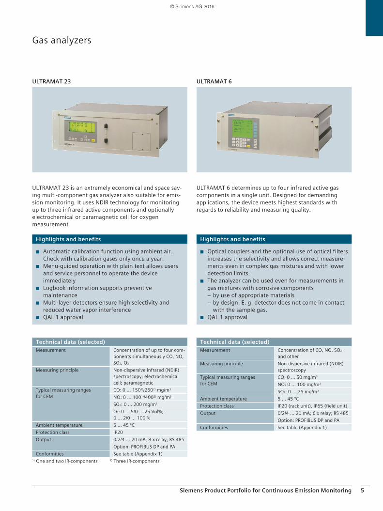
ULTRAMAT 23 is an extremely economical and space sav-ing multi-component gas analyzer also suitable for emis-sion monitoring. It uses NDIR technology for monitoring up to three infrared active components and optionally electrochemical or paramagnetic cell for oxygen measurement.
ULTRAMAT 6 determines up to four infrared active gas components in a single unit. Designed for demanding applications, the device meets highest standards with regards to reliability and measuring quality.
ULTRAMAT 23 ULTRAMAT 6
Gas analyzers
Highlights and benefits
◾ Optical couplers and the optional use of optical filters increases the selectivity and allows correct measure-ments even in complex gas mixtures and with lower detection limits.
◾ The analyzer can be used even for measurements in gas mixtures with corrosive components
– by use of appropriate materials – by design: E. g. detector does not come in contact with the sample gas.
◾ QAL 1 approval
Highlights and benefits
◾ Automatic calibration function using ambient air. Check with calibration gases only once a year.
◾ Menu-guided operation with plain text allows users and service personnel to operate the device immediately
◾ Logbook information supports preventive maintenance
◾ Multi-layer detectors ensure high selectivity and reduced water vapor interference
◾ QAL 1 approval
Technical data (selected)Measurement Concentration of up to four com-
ponents simultaneously CO, NO, SO2, O2
Measuring principle Non-dispersive infrared (NDIR) spectroscopy; electrochemical cell; paramagnetic
Typical measuring ranges for CEM
CO: 0 ... 1501)/2502) mg/m3 NO: 0 ... 1001)/4002) mg/m3
SO2: 0 ... 200 mg/m3
O2: 0 … 5/0 … 25 Vol%; 0 ... 2/0 ... 100 %
Ambient temperature 5 ... 45 °CProtection class IP20 Output 0/2/4 ... 20 mA; 8 x relay; RS 485
Option: PROFIBUS DP and PAConformities See table (Appendix 1)
1) One and two IR-components 2) Three IR-components
Technical data (selected)Measurement Concentration of CO, NO, SO2
and other Measuring principle Non-dispersive infrared (NDIR)
spectroscopyTypical measuring ranges for CEM
CO: 0 ... 50 mg/m3
NO: 0 ... 100 mg/m3
SO2: 0 ... 75 mg/m3
Ambient temperature 5 ... 45 °CProtection class IP20 (rack unit), IP65 (field unit)Output 0/2/4 ... 20 mA; 6 x relay; RS 485
Option: PROFIBUS DP and PAConformities See table (Appendix 1)
© Siemens AG 2016
6 Siemens Product Portfolio for Continuous Emission Monitoring
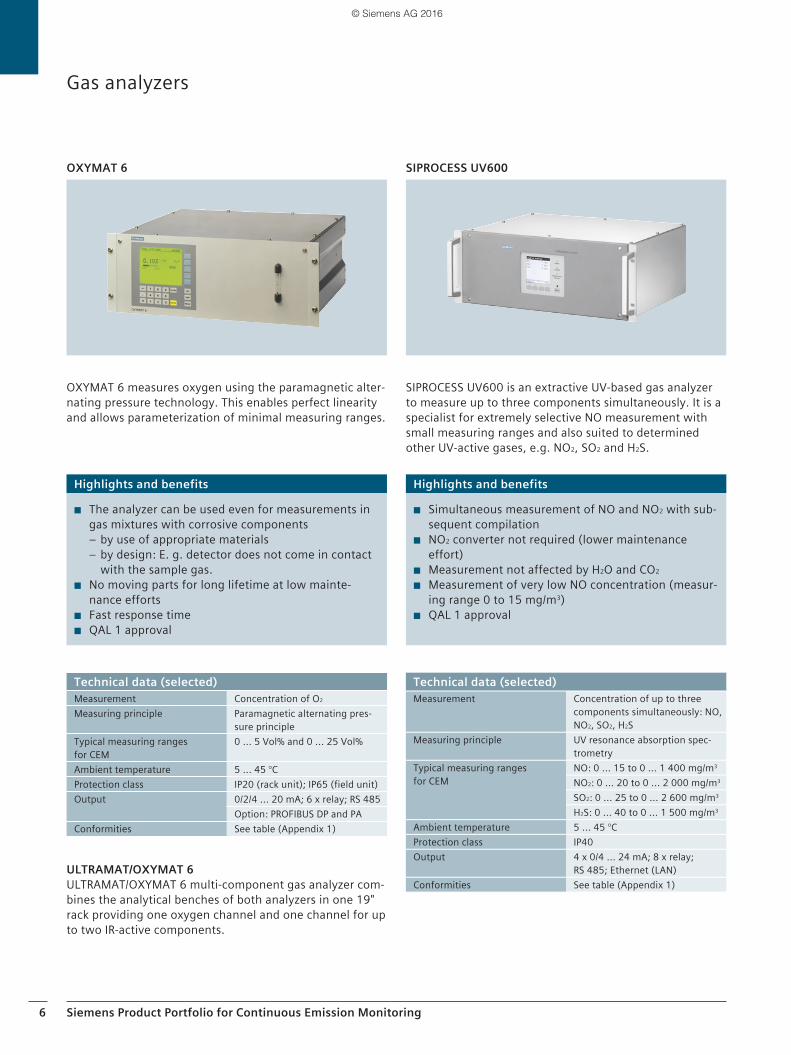
OXYMAT 6 measures oxygen using the paramagnetic alter-nating pressure technology. This enables perfect linearity and allows parameterization of minimal measuring ranges.
SIPROCESS UV600 is an extractive UV-based gas analyzer to measure up to three components simultaneously. It is a specialist for extremely selective NO measurement with small measuring ranges and also suited to determined other UV-active gases, e.g. NO2, SO2 and H2S.
OXYMAT 6 SIPROCESS UV600
ULTRAMAT/OXYMAT 6ULTRAMAT/OXYMAT 6 multi-component gas analyzer com-bines the analytical benches of both analyzers in one 19" rack providing one oxygen channel and one channel for up to two IR-active components.
Gas analyzers
Highlights and benefits
◾ The analyzer can be used even for measurements in gas mixtures with corrosive components
– by use of appropriate materials – by design: E. g. detector does not come in contact with the sample gas.
◾ No moving parts for long lifetime at low mainte-nance efforts
◾ Fast response time ◾ QAL 1 approval
Highlights and benefits
◾ Simultaneous measurement of NO and NO2 with sub-sequent compilation
◾ NO2 converter not required (lower maintenance effort)
◾ Measurement not affected by H2O and CO2
◾ Measurement of very low NO concentration (measur-ing range 0 to 15 mg/m3)
◾ QAL 1 approval
Technical data (selected)Measurement Concentration of O2
Measuring principle Paramagnetic alternating pres-sure principle
Typical measuring ranges for CEM
0 ... 5 Vol% and 0 ... 25 Vol%
Ambient temperature 5 ... 45 °CProtection class IP20 (rack unit); IP65 (field unit)Output 0/2/4 ... 20 mA; 6 x relay; RS 485
Option: PROFIBUS DP and PAConformities See table (Appendix 1)
Technical data (selected)Measurement Concentration of up to three
components simultaneously: NO, NO2, SO2, H2S
Measuring principle UV resonance absorption spec-trometry
Typical measuring ranges for CEM
NO: 0 ... 15 to 0 ... 1 400 mg/m3
NO2: 0 ... 20 to 0 ... 2 000 mg/m3
SO2: 0 ... 25 to 0 ... 2 600 mg/m3
H2S: 0 ... 40 to 0 ... 1 500 mg/m3
Ambient temperature 5 ... 45 °CProtection class IP40Output 4 x 0/4 ... 24 mA; 8 x relay;
RS 485; Ethernet (LAN)Conformities See table (Appendix 1)
© Siemens AG 2016
Siemens Product Portfolio for Continuous Emission Monitoring 7
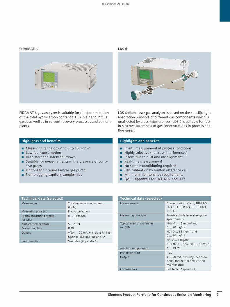
LDS 6 diode laser gas analyzer is based on the specific light absorption principle of different gas components which is unaffected by cross-interferences. LDS 6 is suitable for fast in-situ measurements of gas concentrations in process and flue gases.
LDS 6
FIDAMAT 6 gas analyzer is suitable for the determination of the total hydrocarbon content (THC) in air and in flue gases as well as in solvent recovery processes and cement plants.
FIDAMAT 6
Highlights and benefits
◾ In-situ measurement at process conditions ◾ Highly selective (no cross interferences) ◾ Insensitive to dust and misalignment ◾ Real-time measurement ◾ No sample conditioning required ◾ Self-calibration by built-in reference cell ◾ Minimum maintenance requirements ◾ QAL 1 approvals for HCl, NH3, and H2O
Highlights and benefits
◾ Measuring range down to 0 to 15 mg/m3 ◾ Low fuel consumption ◾ Auto-start and safety shutdown ◾ Suitable for measurements in the presence of corro-
sive gases ◾ Options for internal sample gas pump ◾ Non-plugging capillary sample inlet
Technical data (selected)Measurement Concentration of NH3, NH3/H2O,
H2O, HCl, HCl/H2O, HF, HF/H2O, CO/CO2
Measuring principle Tunable diode laser absorption spectrometry
Typical measuring ranges for CEM
NH3: 0 ... 15 mg/m3 and 0 ... 20 mg/m3
HCl: 0 ... 15 mg/m3 and 0 ... 90 mg/m3
HF: 0 ... 5 mg/m3 CO/CO2: 0 ... 5 Vol %/ 0 ... 10 Vol %
Ambient temperature 5 ... 45 °CProtection class IP20Output 4 ... 20 mA; 6 x relay (per chan-
nel); Ethernet for Service and Maintenance
Conformities See table (Appendix 1)
Technical data (selected)Measurement Total hydrocarbon content
(CnHm)Measuring principle Flame ionizationTypical measuring ranges for CEM
0 ... 15 mg/m3
Ambient temperature 5 ... 45 °CProtection class IP20Output 0/2/4 ... 20 mA; 6 x relay; RS 485
Option: PROFIBUS DP and PAConformities See table (Appendix 1)
© Siemens AG 2016
8 Siemens Product Portfolio for Continuous Emission Monitoring
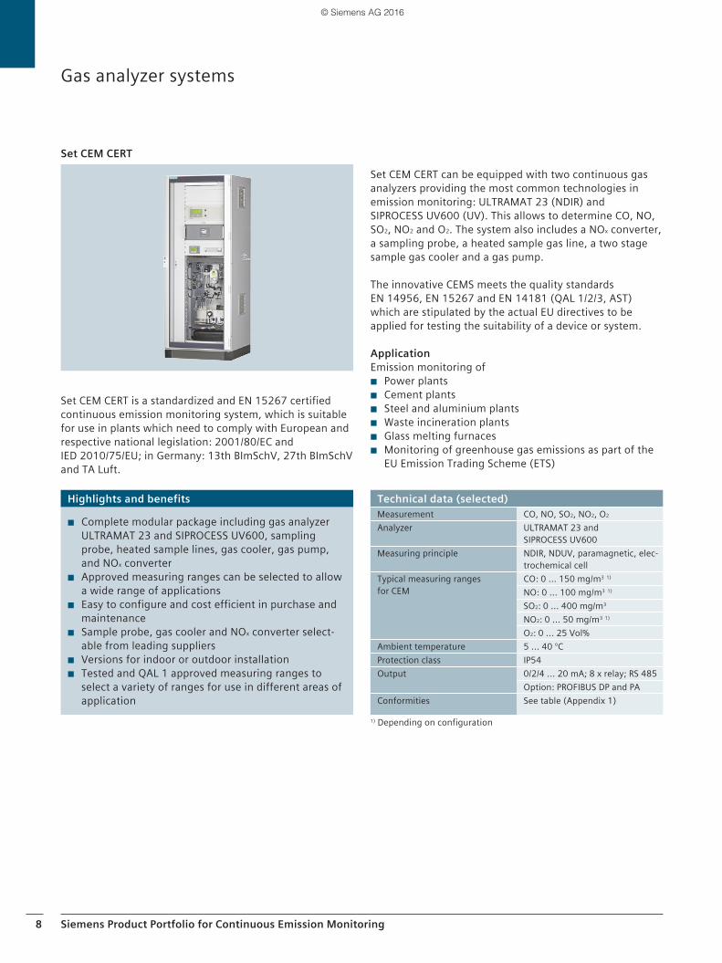
Set CEM CERT is a standardized and EN 15267 certified continuous emission monitoring system, which is suitable for use in plants which need to comply with European and respective national legislation: 2001/80/EC and IED 2010/75/EU; in Germany: 13th BImSchV, 27th BImSchV and TA Luft.
Set CEM CERT
Gas analyzer systems
Set CEM CERT can be equipped with two continuous gas analyzers providing the most common technologies in emission monitoring: ULTRAMAT 23 (NDIR) and SIPROCESS UV600 (UV). This allows to determine CO, NO, SO2, NO2 and O2. The system also includes a NOx converter, a sampling probe, a heated sample gas line, a two stage sample gas cooler and a gas pump.
The innovative CEMS meets the quality standards EN 14956, EN 15267 and EN 14181 (QAL 1/2/3, AST) which are stipulated by the actual EU directives to be applied for testing the suitability of a device or system.
ApplicationEmission monitoring of
◾ Power plants ◾ Cement plants ◾ Steel and aluminium plants ◾ Waste incineration plants ◾ Glass melting furnaces ◾ Monitoring of greenhouse gas emissions as part of the
EU Emission Trading Scheme (ETS)
Highlights and benefits
◾ Complete modular package including gas analyzer ULTRAMAT 23 and SIPROCESS UV600, sampling probe, heated sample lines, gas cooler, gas pump, and NOx converter
◾ Approved measuring ranges can be selected to allow a wide range of applications
◾ Easy to configure and cost efficient in purchase and maintenance
◾ Sample probe, gas cooler and NOx converter select-able from leading suppliers
◾ Versions for indoor or outdoor installation ◾ Tested and QAL 1 approved measuring ranges to
select a variety of ranges for use in different areas of application
Technical data (selected)Measurement CO, NO, SO2, NO2, O2 Analyzer ULTRAMAT 23 and
SIPROCESS UV600Measuring principle NDIR, NDUV, paramagnetic, elec-
trochemical cell Typical measuring ranges for CEM
CO: 0 ... 150 mg/m3 1)
NO: 0 ... 100 mg/m3 1)
SO2: 0 ... 400 mg/m3
NO2: 0 ... 50 mg/m3 1)
O2: 0 ... 25 Vol%Ambient temperature 5 ... 40 °CProtection class IP54 Output 0/2/4 ... 20 mA; 8 x relay; RS 485
Option: PROFIBUS DP and PAConformities See table (Appendix 1)
1) Depending on configuration
© Siemens AG 2016
Siemens Product Portfolio for Continuous Emission Monitoring 9
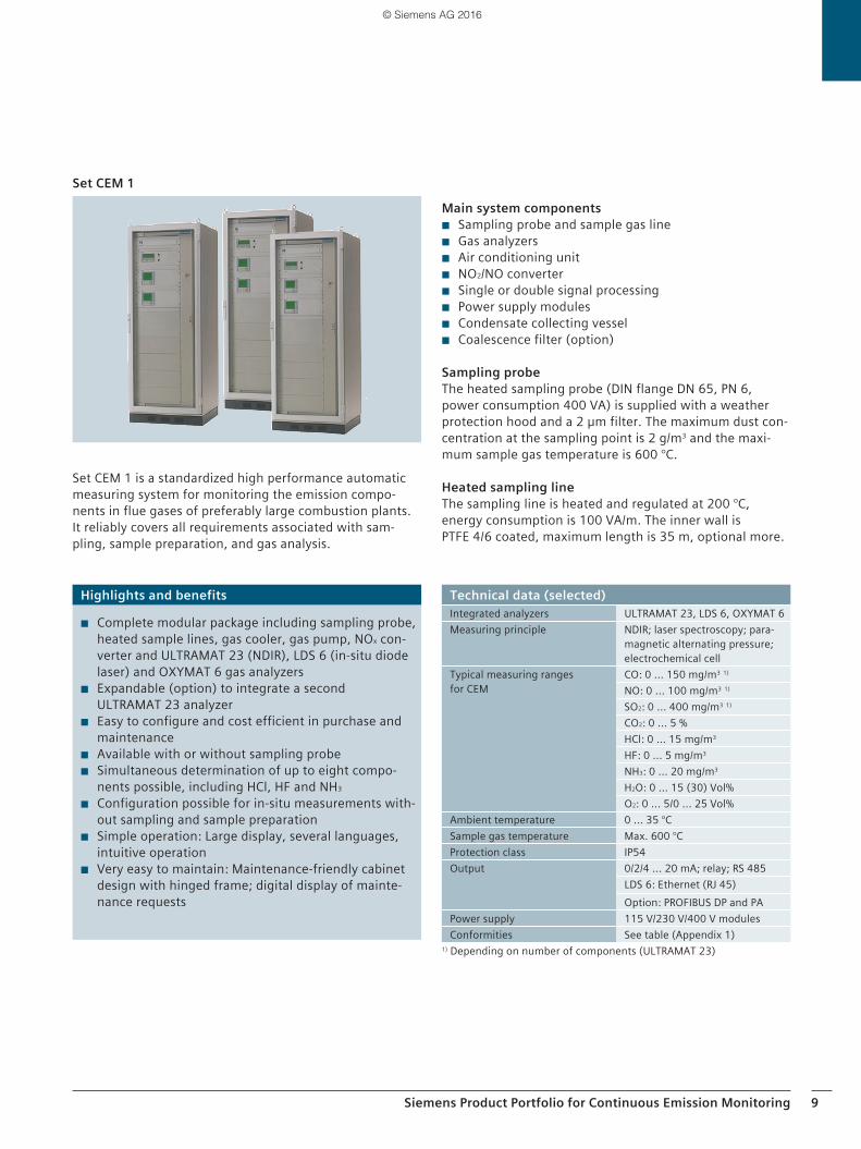
Set CEM 1 is a standardized high performance automatic measuring system for monitoring the emission compo-nents in flue gases of preferably large combustion plants. It reliably covers all requirements associated with sam-pling, sample preparation, and gas analysis.
Set CEM 1Main system components
◾ Sampling probe and sample gas line ◾ Gas analyzers ◾ Air conditioning unit ◾ NO2/NO converter ◾ Single or double signal processing ◾ Power supply modules ◾ Condensate collecting vessel ◾ Coalescence filter (option)
Sampling probeThe heated sampling probe (DIN flange DN 65, PN 6, power consumption 400 VA) is supplied with a weather protection hood and a 2 µm filter. The maximum dust con-centration at the sampling point is 2 g/m3 and the maxi-mum sample gas temperature is 600 °C.
Heated sampling lineThe sampling line is heated and regulated at 200 °C, energy consumption is 100 VA/m. The inner wall is PTFE 4/6 coated, maximum length is 35 m, optional more.
Highlights and benefits
◾ Complete modular package including sampling probe, heated sample lines, gas cooler, gas pump, NOx con-verter and ULTRAMAT 23 (NDIR), LDS 6 (in-situ diode laser) and OXYMAT 6 gas analyzers
◾ Expandable (option) to integrate a second ULTRAMAT 23 analyzer
◾ Easy to configure and cost efficient in purchase and maintenance
◾ Available with or without sampling probe ◾ Simultaneous determination of up to eight compo-
nents possible, including HCl, HF and NH3
◾ Configuration possible for in-situ measurements with-out sampling and sample preparation
◾ Simple operation: Large display, several languages, intuitive operation
◾ Very easy to maintain: Maintenance-friendly cabinet design with hinged frame; digital display of mainte-nance requests
Technical data (selected)Integrated analyzers ULTRAMAT 23, LDS 6, OXYMAT 6Measuring principle NDIR; laser spectroscopy; para-
magnetic alternating pressure; electrochemical cell
Typical measuring ranges for CEM
CO: 0 ... 150 mg/m3 1)
NO: 0 ... 100 mg/m3 1)
SO2: 0 ... 400 mg/m3 1)
CO2: 0 ... 5 % HCl: 0 ... 15 mg/m3
HF: 0 ... 5 mg/m3
NH3: 0 ... 20 mg/m3
H2O: 0 ... 15 (30) Vol%O2: 0 ... 5/0 ... 25 Vol%
Ambient temperature 0 ... 35 °CSample gas temperature Max. 600 °CProtection class IP54 Output 0/2/4 ... 20 mA; relay; RS 485
LDS 6: Ethernet (RJ 45)Option: PROFIBUS DP and PA
Power supply 115 V/230 V/400 V modulesConformities See table (Appendix 1)
1) Depending on number of components (ULTRAMAT 23)
© Siemens AG 2016
10 Siemens Product Portfolio for Continuous Emission Monitoring
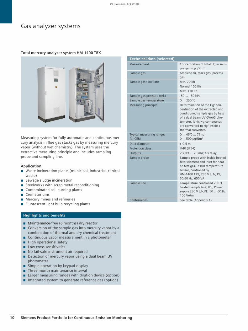
Measuring system for fully-automatic and continuous mer-cury analysis in flue gas stacks gas by measuring mercury vapor (without wet chemistry). The system uses the extractive measuring principle and includes sampling probe and sampling line.
Application ◾ Waste incineration plants (municipal, industrial, clinical
waste) ◾ Sewage sludge incineration ◾ Steelworks with scrap metal reconditioning ◾ Contaminated soil burning plants ◾ Crematoriums ◾ Mercury mines and refineries ◾ Fluorescent light bulb recycling plants
Total mercury analyzer system HM-1400 TRX
Gas analyzer systems
Highlights and benefits
◾ Maintenance-free (6 months) dry reactor ◾ Conversion of the sample gas into mercury vapor by a
combination of thermal and dry chemical treatment ◾ Continuous vapor measurement in a photometer ◾ High operational safety ◾ Low cross sensitivities ◾ No fail-safe instrument air required ◾ Detection of mercury vapor using a dual beam UV
photometer ◾ Simple operation by keypad-display ◾ Three month maintenance interval ◾ Larger measuring ranges with dilution device (option) ◾ Integrated system to generate reference gas (option)
Technical data (selected)Measurement Concentration of total Hg in sam-
ple gas in µg/Nm3 Sample gas Ambient air, stack gas, process
gasSample gas flow rate Min. 70 l/h
Normal 100 l/hMax. 130 l/h
Sample gas pressure (rel.) -50 ... +50 hPaSample gas temperature 0 ... 250 °C Measuring principle Determination of the Hg° con-
centration of the extracted and conditioned sample gas by help of a dual beam UV CVAAS pho-tometer. Ionic Hg-compounds are converted to Hg° inside a thermal converter.
Typical measuring ranges for CEM
0 ... 45/0 ... 75 to 0 ... 500 µg/Nm3
Duct diameter > 0.5 mProtection class IP40 (IP54) Outputs 2 x 0/4 ... 20 mA; 4 x relaySample probe Sample probe with inside heated
filter element and inlet for heat-ed test gas, Pt100 temperature sensor, controlled by HM-1400 TRX, 230 V L, N, PE, 50/60 Hz, 650 VA
Sample line Temperature controlled 200 °C heated sample line, IP5; Power supply 230 V L,N,PE, 50 ... 60 Hz, 100 VA/m
Conformities See table (Appendix 1)
© Siemens AG 2016
Siemens Product Portfolio for Continuous Emission Monitoring 11
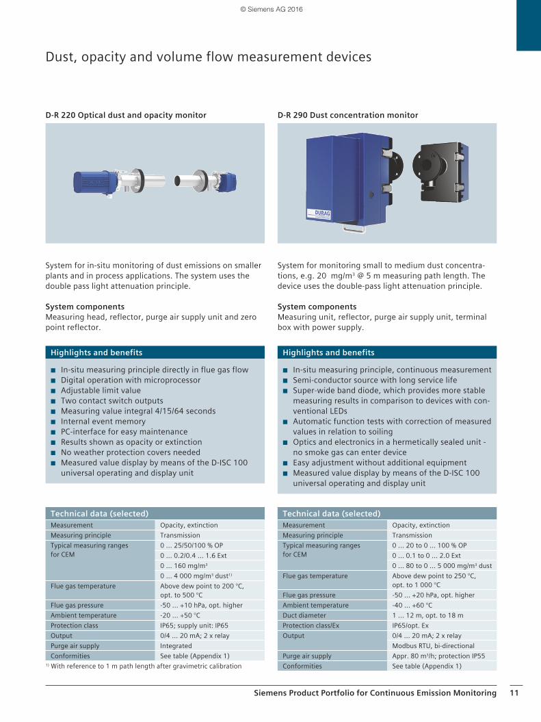
System for in-situ monitoring of dust emissions on smaller plants and in process applications. The system uses the double pass light attenuation principle.
System componentsMeasuring head, reflector, purge air supply unit and zero point reflector.
D-R 220 Optical dust and opacity monitor
Dust, opacity and volume flow measurement devices
System for monitoring small to medium dust concentra-tions, e.g. 20 mg/m3 @ 5 m measuring path length. The device uses the double-pass light attenuation principle.
System componentsMeasuring unit, reflector, purge air supply unit, terminal box with power supply.
D-R 290 Dust concentration monitor
Highlights and benefits
◾ In-situ measuring principle directly in flue gas flow ◾ Digital operation with microprocessor ◾ Adjustable limit value ◾ Two contact switch outputs ◾ Measuring value integral 4/15/64 seconds ◾ Internal event memory ◾ PC-interface for easy maintenance ◾ Results shown as opacity or extinction ◾ No weather protection covers needed ◾ Measured value display by means of the D-ISC 100
universal operating and display unit
Highlights and benefits
◾ In-situ measuring principle, continuous measurement ◾ Semi-conductor source with long service life ◾ Super-wide band diode, which provides more stable
measuring results in comparison to devices with con-ventional LEDs
◾ Automatic function tests with correction of measured values in relation to soiling
◾ Optics and electronics in a hermetically sealed unit - no smoke gas can enter device
◾ Easy adjustment without additional equipment ◾ Measured value display by means of the D-ISC 100
universal operating and display unit
Technical data (selected)Measurement Opacity, extinctionMeasuring principle TransmissionTypical measuring ranges for CEM
0 ... 25/50/100 % OP 0 ... 0.2/0.4 ... 1.6 Ext0 ... 160 mg/m3
0 ... 4 000 mg/m3 dust1)
Flue gas temperature Above dew point to 200 °C, opt. to 500 °C
Flue gas pressure -50 ... +10 hPa, opt. higherAmbient temperature -20 ... +50 °CProtection class IP65; supply unit: IP65Output 0/4 ... 20 mA; 2 x relay Purge air supply IntegratedConformities See table (Appendix 1)
1) With reference to 1 m path length after gravimetric calibration
Technical data (selected)Measurement Opacity, extinctionMeasuring principle TransmissionTypical measuring ranges for CEM
0 ... 20 to 0 ... 100 % OP0 ... 0.1 to 0 ... 2.0 Ext0 ... 80 to 0 ... 5 000 mg/m3 dust
Flue gas temperature Above dew point to 250 °C, opt. to 1 000 °C
Flue gas pressure -50 ... +20 hPa, opt. higherAmbient temperature -40 ... +60 °CDuct diameter 1 ... 12 m, opt. to 18 mProtection class/Ex IP65/opt. ExOutput 0/4 ... 20 mA; 2 x relay
Modbus RTU, bi-directionalPurge air supply Appr. 80 m3/h; protection IP55Conformities See table (Appendix 1)
© Siemens AG 2016
12 Siemens Product Portfolio for Continuous Emission Monitoring
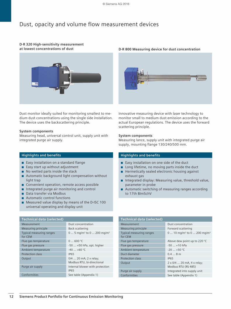
Innovative measuring device with laser technology to monitor small to medium dust emission according to the actual European regulations. The device uses the forward scattering principle.
System componentsMeasuring lance, supply unit with integrated purge air supply, mounting flange 130/240/500 mm.
D-R 800 Measuring device for dust concentration
Dust monitor ideally suited for monitoring smallest to me-dium dust concentrations using the single side installation. The device uses the backscattering principle.
System componentsMeasuring head, universal control unit, supply unit with integrated purge air supply.
D-R 320 High-sensitivity measurement at lowest concentrations of dust
Dust, opacity and volume flow measurement devices
Highlights and benefits
◾ Easy installation on one side of the duct ◾ Long lifetime, no moving parts inside the duct ◾ Hermetically sealed electronic housing against
exhaust gas ◾ Integrated display: Measuring value, threshold value,
parameter in probe ◾ Automatic switching of measuring ranges according
to 17th BImSchV
Highlights and benefits
◾ Easy installation on a standard flange ◾ Easy start up without adjustment ◾ No wetted parts inside the stack ◾ Automatic background light compensation without
light trap ◾ Convenient operation, remote access possible ◾ Integrated purge air monitoring and control ◾ Data transfer via Modbus ◾ Automatic control functions ◾ Measured value display by means of the D-ISC 100
universal operating and display unit
Technical data (selected)Measurement Dust concentrationMeasuring principle Forward scatteringTypical measuring ranges for CEM
0 ... 10 mg/m3 to 0 ... 200 mg/m3
Flue gas temperature Above dew point up to 220 °CFlue gas pressure -50 ... +10 hPaAmbient temperature -20 ... +50 °CDuct diameter 0.4 ... 8 mProtection class IP65Output 2 x 0/4 ... 20 mA, 4 x relay;
Modbus RTU (RS 485)Purge air supply Integrated into supply unitConformities See table (Appendix 1)
Technical data (selected)Measurement Dust concentrationMeasuring principle Back scatteringTypical measuring ranges for CEM
0 ... 5 mg/m3 to 0 ... 200 mg/m3
Flue gas temperature 0 ... 600 °C Flue gas pressure -50 ... +50 hPa, opt. higherAmbient temperature -40 ... +60 °CProtection class IP65Output 0/4 ... 20 mA; 2 x relay;
Modbus RTU, bi-directional Purge air supply Internal blower with protection
IP65Conformities See table (Appendix 1)
© Siemens AG 2016
Siemens Product Portfolio for Continuous Emission Monitoring 13
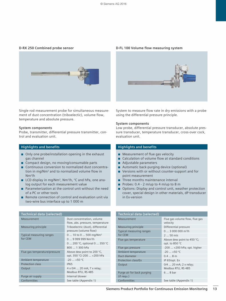
Single rod measurement probe for simultaneous measure-ment of dust concentration (triboelectic), volume flow, temperature and absolute pressure.
System componentsProbe, transmitter, differential pressure transmitter, con-trol and evaluation unit.
D-RX 250 Combined probe sensor
System to measure flow rate in dry emissions with a probe using the differential pressure principle.
System componentsLow probe, differential pressure transducer, absolute pres-sure transducer, temperature transducer, cross-over cock, evaluation unit.
D-FL 100 Volume flow measuring system
Highlights and benefits
◾ Only one probe/installation opening in the exhaust gas channel
◾ Compact design, no moving/consumable parts ◾ Continuous conversion to normalized dust concentra-
tion in mg/Nm3 and to normalized volume flow in Nm3/h
◾ LCD display in mg/Nm3, Nm3/h, °C and hPa, one ana-log output for each measurement value
◾ Parameterization at the control unit without the need of a PC or other tools
◾ Remote connection of control and evaluation unit via two-wire bus interface up to 1 000 m
Highlights and benefits
◾ Measurement of flue gas velocity ◾ Calculation of volume flow at standard conditions ◾ Adjustable parameters ◾ Automatic back-purging device (optional) ◾ Versions with or without counter-support and for
point measurement ◾ Three months maintenance interval ◾ Probes: 0.4 - 2 m/up to 4 m/up to 8 m ◾ Options: Display and control unit, weather protection
cover, special design in other materials, dP transducer in Ex-version
Technical data (selected)Measurement Dust concentration, volume
flow, abs. pressure, temperatureMeasuring principle Triboelectric (dust), differential
pressure (volume flow)Typical measuring ranges for CEM
0 ... 10 to 0 ... 500 mg/Nm3 0 ... 9 999 999 Nm3/h0 ... 200 °C, optional 0 ... 350 °C800 ... 1 300 hPa
Flue gas temperature/pressure Above dew point to 200 °C, opt. 350 °C/-200 ... +200 hPa
Ambient temperature -20 ... +50 °C Protection class IP65Output 4 x 0/4 ... 20 mA; 7 x relay;
Modbus RTU, RS 485Purge air supply Internal blowerConformities See table (Appendix 1)
Technical data (selected)Measurement Flue gas volume flow, flue gas
velocityMeasuring principle Differential pressure Typical measuring ranges for CEM
0 ... 3 000 000 m3/h 2 ... 50 m/s
Flue gas temperature Above dew point to 450 °C; opt. to 850 °C
Flue gas pressure -200 ... +200 hPa; opt. higher Ambient temperature -20 ... +50 °CDuct diameter 0.4 ... 8 mProtection class/Ex IP 65/opt. ExOutput 0/4 ... 20 mA; 2 x relay;
Modbus RTU, RS 485 Purge air for back purging (if requ.)
6 ... 8 bar
Conformities See table (Appendix 1)
© Siemens AG 2016
14 Siemens Product Portfolio for Continuous Emission Monitoring
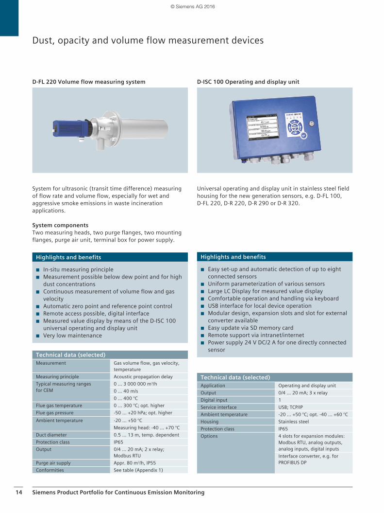
System for ultrasonic (transit time difference) measuring of flow rate and volume flow, especially for wet and aggressive smoke emissions in waste incineration applications.
System componentsTwo measuring heads, two purge flanges, two mounting flanges, purge air unit, terminal box for power supply.
D-FL 220 Volume flow measuring system
Universal operating and display unit in stainless steel field housing for the new generation sensors, e.g. D-FL 100, D-FL 220, D-R 220, D-R 290 or D-R 320.
D-ISC 100 Operating and display unit
Dust, opacity and volume flow measurement devices
Highlights and benefits
◾ In-situ measuring principle ◾ Measurement possible below dew point and for high
dust concentrations ◾ Continuous measurement of volume flow and gas
velocity ◾ Automatic zero point and reference point control ◾ Remote access possible, digital interface ◾ Measured value display by means of the D-ISC 100
universal operating and display unit ◾ Very low maintenance
Highlights and benefits
◾ Easy set-up and automatic detection of up to eight connected sensors
◾ Uniform parameterization of various sensors ◾ Large LC Display for measured value display ◾ Comfortable operation and handling via keyboard ◾ USB interface for local device operation ◾ Modular design, expansion slots and slot for external
converter available ◾ Easy update via SD memory card ◾ Remote support via intranet/internet ◾ Power supply 24 V DC/2 A for one directly connected
sensorTechnical data (selected)Measurement Gas volume flow, gas velocity,
temperatureMeasuring principle Acoustic propagation delayTypical measuring ranges for CEM
0 ... 3 000 000 m3/h0 ... 40 m/s 0 ... 400 °C
Flue gas temperature 0 ... 300 °C; opt. higherFlue gas pressure -50 ... +20 hPa; opt. higherAmbient temperature -20 ... +50 °C
Measuring head: -40 ... +70 °CDuct diameter 0.5 ... 13 m, temp. dependentProtection class IP65Output 0/4 ... 20 mA; 2 x relay;
Modbus RTUPurge air supply Appr. 80 m3/h, IP55Conformities See table (Appendix 1)
Technical data (selected)Application Operating and display unitOutput 0/4 ... 20 mA; 3 x relayDigital input 1Service interface USB; TCP/IPAmbient temperature -20 ... +50 °C; opt. -40 ... +60 °CHousing Stainless steelProtection class IP65Options 4 slots for expansion modules:
Modbus RTU, analog outputs, analog inputs, digital inputs Interface converter, e.g. for PROFIBUS DP
© Siemens AG 2016
Siemens Product Portfolio for Continuous Emission Monitoring 15
Sample probe
A CEM system usually consists of an extractive measuring device and uses a sample probe for extracting samples of flue gas. However, for some measuring components there are also in-situ analysis solutions available. Depending on process conditions, gas matrix (measuring ranges, and interferants, e. g. water, aerosols content) cold- or hot-extractive sampling methods are used.
For hot-extractive sampling a typical stack-gas sample probe is supplied with a one meter stainless steel insertion probe and a heated ceramic filter element with two micron pore size. For optimum performance, the filter is thermo-statically regulated to at least 180 °C. Optionally ATEX rated probes, suitable for safe-area operation, are avail-able. The probe and filter are typically mounted on a DN 65/PN 6 flange and all gas-wetted components are manufactured from stainless steel. The whole assembly is designed for operation in harsh and rugged environments and can be supplied with an optional weatherproof cover.
Electrical heating is particularly secure and robust with no external elements or wiring. The complete filter unit is brought up to operating temperature in a controlled fash-ion to prevent premature burn-out of the heater elements and is automatically controlled. An alarm is available to signify an over/under temperature alarm condition. Ceramic cartridge filters in a wide range of pore sizing are available to suit various applications. The probe assembly is also provided with a test gas port, enabling the whole sample transport system to be challenged for integrity and response time as required.
Heated sample lines
For the sample transport line, typically a 20 m thermostati-cally controlled, trace heated and insulated line, running at 180 °C is included. The sample line is generally 4/6 mm diameter PTFE with stainless steel braiding and is available up to a maximum length of 54 m. Outer sheath is typically of 43 mm diameter, waterproof and flame retardant Poly-amide with CFC-free thermo-fleece insulation layer. Ther-mostatic control with Pt100 or K-type temperature sensor ensures optimum control and stability. Line consumption is approximately 100 - 120 W/m. The sample line should be routed so as to provide a consistent downward slope from the probe to the analyzer shelter avoiding any hollows in which condensed water vapor can collect.
Components for system integration
Sample conditioning system
With all analysis applications it is important to present the gas to the analyzers in a clean (free from particulate and moisture) and temperature controlled condition to ensure accurate and trouble free operation. For this reason a fully-configured sample conditioning system is provided along with heated sample probe and transport lines to ensure preservation of sample gas quality.
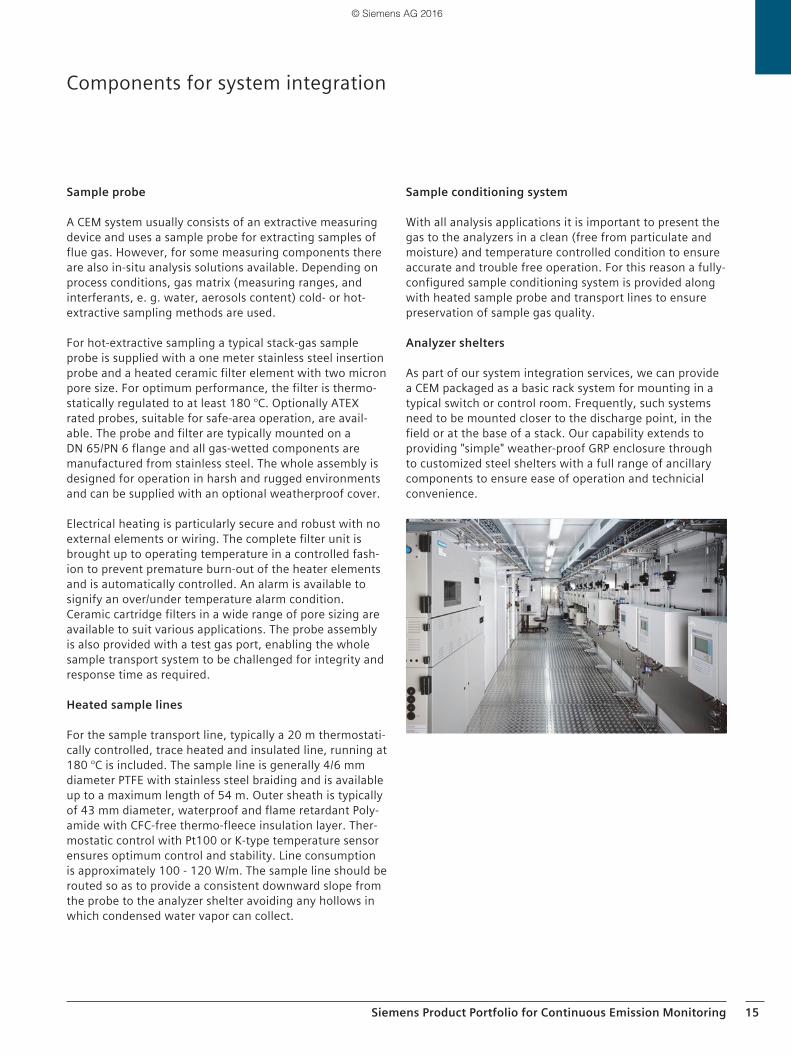
Analyzer shelters
As part of our system integration services, we can provide a CEM packaged as a basic rack system for mounting in a typical switch or control room. Frequently, such systems need to be mounted closer to the discharge point, in the field or at the base of a stack. Our capability extends to providing "simple" weather-proof GRP enclosure through to customized steel shelters with a full range of ancillary components to ensure ease of operation and technicial convenience.
© Siemens AG 2016
16 Siemens Product Portfolio for Continuous Emission Monitoring
For emission data management, Siemens may provide both, dedicated regional as well as international solu-tions. Please contact your local Siemens Process Analytics sales organization for appropriate solution.
Dedicated regional Siemens solutions
Examples for dedicated Siemens solutions available in some regions are CEM System Manager (CSM), EMIDATE Software, or US Data Acquisition System (DAS) also for CEM applications.
CEM System Manager (CSM, Siemens UK)On power generation plants, typically three separate con-trol systems exist:
◾ Process control system for control and monitoring of all the plant items
◾ Emissions monitoring system (gas analyzers) to provide the necessary continuous measurement of the compo-nents of the exhaust gases
◾ Data acquisition and operating system to record the data from the emissions monitoring analyzers and gen-erate the necessary reports to comply relevant emis-sions directive
Three in one, MCERTS approvedUntil now, these systems have often been supplied by dif-ferent manufacturer with limited interfacing possibilities. This is why Siemens UK developed CEM System Manager (CSM) which is a MCERTS approved emissions reporting package and is an integral part of our PCS7 distributed control system. It brings together three separate systems into one, enabling you not only to comply with the envi-ronmental regulations but also to improve the operational efficiency of your plant.
EMIDATE Software (Siemens Austria) The software solution EMIDATE from Siemens Austria col-lects, monitors, evaluates and stores all emission related values and plant states. This allows the monitoring of pol-lutants to permissible limits. The results are graphically visualized and stored.
TÜV-certifiedThe current version 6.0 was certified by TÜV Austria based on:
◾ ÖNORM M9412-1:2008 (System 3) ◾ ÖNORM M9412-2:2008 ◾ ONR 19412-1:2012
Emission data management systems
Modular systemThe system is modular and relies on proven standard com-ponents. The data acquisition is done via the industry stan-dard PROFIBUS.
Significant new features of version 6.0 ◾ Expandable multilingualism ◾ Freely adjustable actual value and compression cycles ◾ Easy access to stored data (graphs and tables) ◾ Data of various emission servers can be visualized in
one picture ◾ Acknowledgment for messages including alerting (digi-
tal output, PC)
Data Acquisition System (DAS) solutions (Siemens USA)The DAS solution from Siemens USA is suitable for 40 CFR 60, 63 and 75 and includes: one PC, local rack mount and industrial type EMC station manager software for commu-nications with a Siemens S7 1200 PLC.
DURAG emission data management solutions
Family of modular data acquisition and handling systems (DAHS) for management of environmental and process data according to European & US-EPA regulations:
◾ D-EMS 2000 – TÜV certified according to EN 15267 – MCERTS certified
◾ D-EMS 2000 CS – Price effective compact system for small and middle sized plants
– TÜV certified according to EN 15267 ◾ D-DAS 2010
– Cost effective system – MCERTS certified
◾ D-DAS 2000 – Cost effective system – Excellent cost/performance ratio
◾ UTAS Dr. Lasinger – Cost effective system for the Austrian Market – ÖNORM M9412-2 certified by TÜV Austria
© Siemens AG 2016
Siemens Product Portfolio for Continuous Emission Monitoring 17
Data acquisition, evaluation and reporting according to: ◾ European Industrial Emissions Directive (IED)
2010/75/EU ◾ US EPA 40 CFR Part 60,63 & 75 ◾ GHG Emission Monitoring (European-, UNFCCC- Guide-
lines, etc.) ◾ Country-specific requirements
Management for ◾ Emission data ◾ Water data ◾ Greenhouse gas (GHG) data ◾ Ambient air data ◾ Meteorological data ◾ Process data etc.
Approvals ◾ Suitability-tested by TÜV in accordance with German
TA Luft, 1st, 2nd, 13th, 17th, 27th, 30th and 31st BImSchV as well as the European Directives 2010/75/EU, 2000/76/EC and 2001/80/EC considering EN 14181
◾ QAL 1 approved according to EN 15267 ◾ MCERTS certified
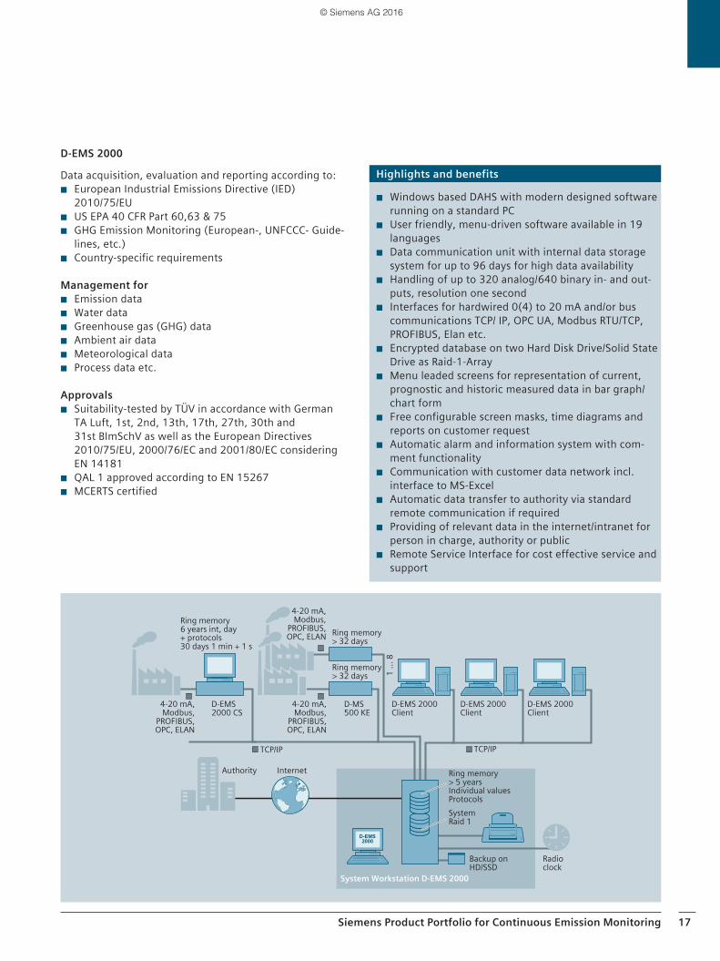
D-EMS 2000
1 ...
8
Ring memory 6 years int, day + protocols 30 days 1 min + 1 s
4-20 mA, Modbus,
PROFIBUS, OPC, ELAN
4-20 mA, Modbus,
PROFIBUS, OPC, ELAN
Ring memory > 32 days
Ring memory > 32 days
D-MS 500 KE
D-EMS 2000 CS
TCP/IP TCP/IP
Authority Internet
System Workstation D-EMS 2000
Radio clock
Backup on HD/SSD
System Raid 1
Ring memory> 5 yearsIndividual valuesProtocols
D-EMS 2000 Client
D-EMS 2000 Client
D-EMS 2000 Client
4-20 mA, Modbus,
PROFIBUS, OPC, ELAN
Highlights and benefits
◾ Windows based DAHS with modern designed software running on a standard PC
◾ User friendly, menu-driven software available in 19 languages
◾ Data communication unit with internal data storage system for up to 96 days for high data availability
◾ Handling of up to 320 analog/640 binary in- and out-puts, resolution one second
◾ Interfaces for hardwired 0(4) to 20 mA and/or bus communications TCP/ IP, OPC UA, Modbus RTU/TCP, PROFIBUS, Elan etc.
◾ Encrypted database on two Hard Disk Drive/Solid State Drive as Raid-1-Array
◾ Menu leaded screens for representation of current, prognostic and historic measured data in bar graph/ chart form
◾ Free configurable screen masks, time diagrams and reports on customer request
◾ Automatic alarm and information system with com-ment functionality
◾ Communication with customer data network incl. interface to MS-Excel
◾ Automatic data transfer to authority via standard remote communication if required
◾ Providing of relevant data in the internet/intranet for person in charge, authority or public
◾ Remote Service Interface for cost effective service and support
© Siemens AG 2016
18 Siemens Product Portfolio for Continuous Emission Monitoring
Price effective compact system for data acquisition and handling for small and middle sized plants
OptionsThree device types are available:
◾ 19" 3HU rack with monitor/keyboard/mouse ◾ 19" 1HU unit with slide-in keyboard and retractable
monitor ◾ Desktop version with monitor/keyboard/mouse
ApplicationsEmissions evaluation computer for small to medium-sized installations in all types of plants and industries
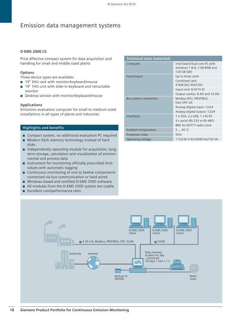
D-EMS 2000 CS
TCP/IP
Ring memory 6 years int, day + protocols 30 days 1 min + 1 s
4-20 mA, Modbus, PROFIBUS, OPC, ELAN
Authority Internet
Radio clock
Backup on HD/SSD
D-EMS 2000 Client
D-EMS 2000 Client
D-EMS 2000 Client
Emission data management systems
Highlights and benefits
◾ Compact system, no additional evaluation PC required ◾ Modern flash memory technology instead of hard
disks ◾ Independently operating module for acquisition, long-
term storage, calculation and visualization of environ-mental and process data
◾ Instrument for monitoring officially prescribed limit values with automatic logging
◾ Continuous monitoring of one to twelve components connected via bus communication or hard wired
◾ Windows based and certified D-EMS 2000 software ◾ All modules from the D-EMS 2000 system are usable ◾ Excellent cost/performance ratio
Technical data (selected)Computer Intel based Dual core PC with
windows 7 & 8, 2 GB RAM and 120 GB SDD
Input/ouput Up to three cardsCombined card: 4 AI/8 DI/2 AO/4 DOInput card: 8 AI/15 DIOutput card(s): 8 AO and 16 DO
Bus system connection Modbus RTU, PROFIBUS, Elan OPC UAAnalog-/digital input: 12/24Analog-/digital output: 12/24
Interfaces 1 x VGA, 2 x USB, 1 x RJ 453 x serial (RS 232 or RS 485)BNC for DCF77-radio clock
Ambient temperature 5 ... 40 °CProtection class IP20Operating voltage 115/230 V AC/50/60 Hz/100 VA
© Siemens AG 2016
Siemens Product Portfolio for Continuous Emission Monitoring 19
Documentation
The system will be supplied with individual componentoperating and maintenance manuals along with project specific documentation comprising:
◾ System schematic ◾ System piping diagrams ◾ System operating & maintenance manual ◾ Individual analyzer manuals ◾ Maintenance schedule ◾ Factory test & calibration certificates
Commissioning and start-up
Should your project be a new-build or upgrade, we can provide installation services as part of our project managed delivery. A typical scope would include site survey, prepa-ration of installation drawings, materials supply and man-agement services. Alternatively, our assigned project team can coordinate with your nominated contractor to ensure a seamless process. Installation services will be subject to a separate offer.
Not included, but available at our standard service rates, we offer the services of project trained commissioning engineer to assist with start-up and first-level operator training.
We realize that the purpose of an emissions monitoring system is to enable our customers to comply with the law. Therefore the focus of our after-sales offer is on risk miti-gation. Every aspect of our support and training portfolio is intended to minimize the risk of downtime and to ensure that any problem is rectified as quickly as possible. Given the stringent limits (and penalties for non-compliance) applied by the environment agencies to permissible down-time of a CEMS, we think it is critical that the supplier of the CEMS should play their part in making sure that these limits are not reached.
Examples for risk mitigations are:
Helpdesk (technical and telephone support)Rapid access to trained staff in the event of a problem
Field serviceResponse to site in the event that a site visit is needed to solve the problem
Spares and repairsWe compile our spares lists to include items that genu-inely reduce the risk of downtime, because they can be changed on site and avoid the need for sending equipment off site for repair
Planned maintenanceReducing the risk of unscheduled downtime
Service level agreementsBringing the above elements together into a contract that defines the expectations of both parties
TrainingEnabling your operational staff to be the first line of diag-nosis and repair
Extended scope of supply After sales support
© Siemens AG 2016
20 Emission Control Guidelines driven by UNFCCC
Emission Control Guidelines driven by UNFCCCEuropean "air quality" directives and standards
Effective monitoring, reporting and verification of green-house gas (GHG) emissions is critical for tracking progress towards the achievement of emission reduction targets. The ultimate goal of the UN Framework Convention on Cli-mate Change (UNFCCC) is to stabilize atmospheric concen-trations of GHGs at a level which prevents dangerous human interference with the climate system.All parties and member states to the UNFCCC, its Kyoto Protocol and Paris Agreement are required to report annu-ally on their GHG emissions. Therefore emission control guidelines and Quality Assurance (QA) and Quality Control (QC) Systems have been developed and implemented in different parts of the world to ensure these targets.
European "air quality" directives and standards
European policy concerning the protection of the environ-ment has steadily grown in importance. In particular, the Treaty of Amsterdam (1997) has made a high-level of envi-ronmental protection including air quality one of the top priorities. The European Community has aimed to develop an overall strategy and adopted new directives which refer to issues of ambient air quality as well as to stationary source emissions or automotive fuel quality and even to pollutant emission from ships.
Directives for stationary source emissions
Industrial Emissions Directive (IED) 2010/75/EU
The IED (Industrial Emissions Directive of November 24, 2010 on the integrated pollution prevention and control) is the integrated approach to avoid or minimize polluting emissions in the atmosphere, water and soil, as well as waste from industrial and agricultural installations, with the aim of achieving a high level of environmental and health protection.
The IED came into force on January 6, 2011 and is now transposed into national law of EU member states. The long IED recasts seven former, separate existing directives related to industrial emissions as annexes of the IED, see table below.
This provides a single, central document for industry. The former directives are now replaced by the IED.
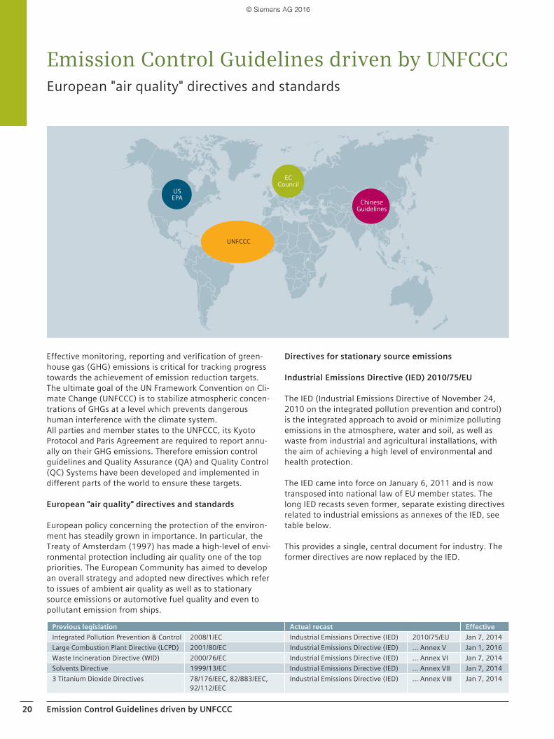
US EPA
UNFCCC
EC Council
Chinese Guidelines
Previous legislation Actual recast EffectiveIntegrated Pollution Prevention & Control 2008/1/EC Industrial Emissions Directive (IED) 2010/75/EU Jan 7, 2014Large Combustion Plant Directive (LCPD) 2001/80/EC Industrial Emissions Directive (IED) … Annex V Jan 1, 2016Waste Incineration Directive (WID) 2000/76/EC Industrial Emissions Directive (IED) … Annex VI Jan 7, 2014Solvents Directive 1999/13/EC Industrial Emissions Directive (IED) … Annex VII Jan 7, 20143 Titanium Dioxide Directives 78/176/EEC, 82/883/EEC,
92/112/EECIndustrial Emissions Directive (IED) … Annex VIII Jan 7, 2014
© Siemens AG 2016
Emission Control Guidelines driven by UNFCCC 21
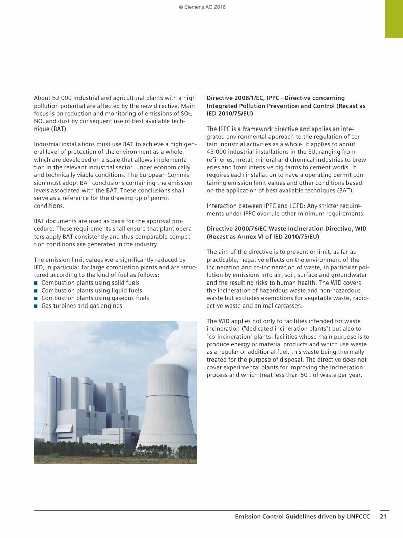
About 52 000 industrial and agricultural plants with a high pollution potential are affected by the new directive. Main focus is on reduction and monitoring of emissions of SO2, NOx and dust by consequent use of best available tech-nique (BAT).
Industrial installations must use BAT to achieve a high gen-eral level of protection of the environment as a whole, which are developed on a scale that allows implementa-tion in the relevant industrial sector, under economically and technically viable conditions. The European Commis-sion must adopt BAT conclusions containing the emission levels associated with the BAT. These conclusions shall serve as a reference for the drawing up of permit conditions.
BAT documents are used as basis for the approval pro-cedure. These requirements shall ensure that plant opera-tors apply BAT consistently and thus comparable competi-tion conditions are generated in the industry.
The emission limit values were significantly reduced by IED, in particular for large combustion plants and are struc-tured according to the kind of fuel as follows:
◾ Combustion plants using solid fuels ◾ Combustion plants using liquid fuels ◾ Combustion plants using gaseous fuels ◾ Gas turbines and gas engines
Directive 2008/1/EC, IPPC - Directive concerning Integrated Pollution Prevention and Control (Recast as IED 2010/75/EU)
The IPPC is a framework directive and applies an inte-grated environmental approach to the regulation of cer-tain industrial activities as a whole. It applies to about 45 000 industrial installations in the EU, ranging from refineries, metal, mineral and chemical industries to brew-eries and from intensive pig farms to cement works. It requires each installation to have a operating permit con-taining emission limit values and other conditions based on the application of best available techniques (BAT).
Interaction between IPPC and LCPD: Any stricter require-ments under IPPC overrule other minimum requirements.
Directive 2000/76/EC Waste Incineration Directive, WID (Recast as Annex VI of IED 2010/75/EU)
The aim of the directive is to prevent or limit, as far as practicable, negative effects on the environment of the incineration and co-incineration of waste, in particular pol-lution by emissions into air, soil, surface and groundwater and the resulting risks to human health. The WID covers the incineration of hazardous waste and non-hazardous waste but excludes exemptions for vegetable waste, radio-active waste and animal carcasses.
The WID applies not only to facilities intended for waste incineration ("dedicated incineration plants") but also to "co-incineration" plants: facilities whose main purpose is to produce energy or material products and which use waste as a regular or additional fuel, this waste being thermally treated for the purpose of disposal. The directive does not cover experimental plants for improving the incineration process and which treat less than 50 t of waste per year.
© Siemens AG 2016
22 Emission Control Guidelines driven by UNFCCC
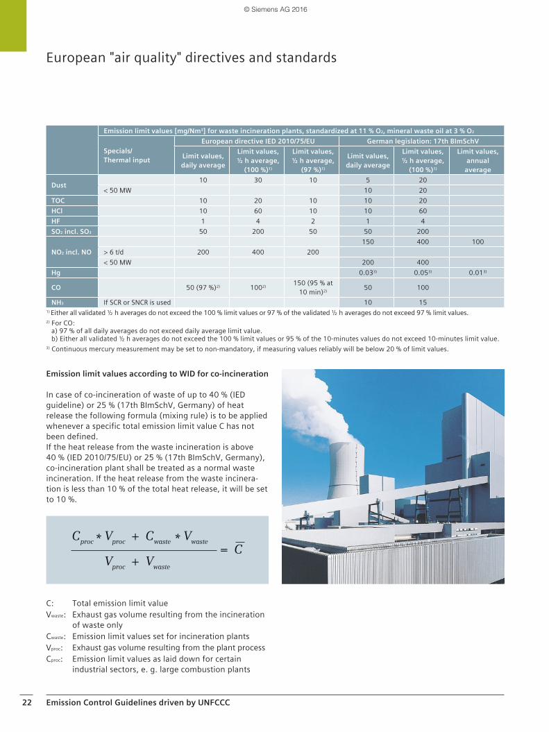
Emission limit values according to WID for co-incineration
In case of co-incineration of waste of up to 40 % (IED guideline) or 25 % (17th BImSchV, Germany) of heat release the following formula (mixing rule) is to be applied whenever a specific total emission limit value C has not been defined. If the heat release from the waste incineration is above 40 % (IED 2010/75/EU) or 25 % (17th BImSchV, Germany), co-incineration plant shall be treated as a normal waste incineration. If the heat release from the waste incinera-tion is less than 10 % of the total heat release, it will be set to 10 %.
C: Total emission limit valueVwaste: Exhaust gas volume resulting from the incineration
of waste onlyCwaste: Emission limit values set for incineration plantsVproc: Exhaust gas volume resulting from the plant processCproc: Emission limit values as laid down for certain
industrial sectors, e. g. large combustion plants
European "air quality" directives and standards
Emission limit values [mg/Nm3] for waste incineration plants, standardized at 11 % O2, mineral waste oil at 3 % O2
Specials/Thermal input
European directive IED 2010/75/EU German legislation: 17th BImSchV
Limit values, daily average
Limit values, ½ h average,
(100 %)1)
Limit values, ½ h average,
(97 %)1)
Limit values, daily average
Limit values, ½ h average,
(100 %)1)
Limit values, annual
average
Dust 10 30 10 5 20< 50 MW 10 20
TOC 10 20 10 10 20HCl 10 60 10 10 60HF 1 4 2 1 4SO2 incl. SO3 50 200 50 50 200
NO2 incl. NO150 400 100
> 6 t/d 200 400 200< 50 MW 200 400
Hg 0.033) 0.053) 0.013)
CO 50 (97 %)2) 1002) 150 (95 % at 10 min)2) 50 100
NH3 If SCR or SNCR is used 10 151) Either all validated ½ h averages do not exceed the 100 % limit values or 97 % of the validated ½ h averages do not exceed 97 % limit values.2) For CO:
a) 97 % of all daily averages do not exceed daily average limit value.b) Either all validated ½ h averages do not exceed the 100 % limit values or 95 % of the 10-minutes values do not exceed 10-minutes limit value.
3) Continuous mercury measurement may be set to non-mandatory, if measuring values reliably will be below 20 % of limit values.
© Siemens AG 2016
Emission Control Guidelines driven by UNFCCC 23
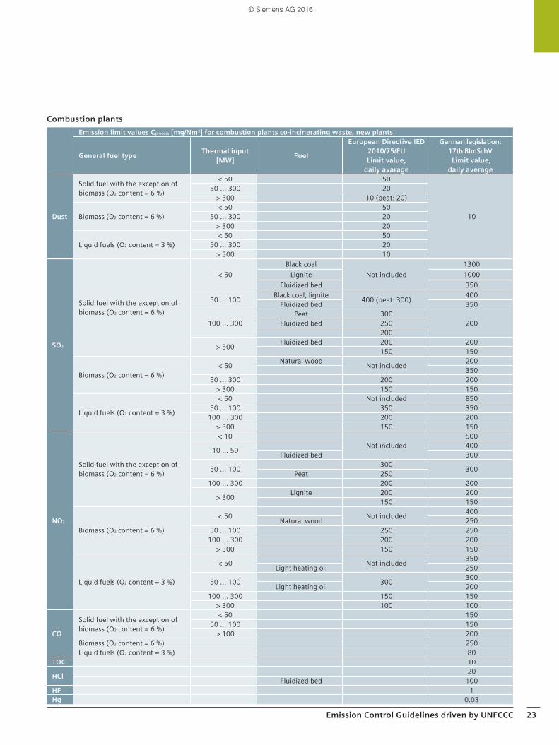
Combustion plantsEmission limit values Cprocess [mg/Nm3] for combustion plants co-incinerating waste, new plants
General fuel type Thermal input [MW] Fuel
European Directive IED 2010/75/EULimit value,
daily avarage
German legislation: 17th BImSchV Limit value,
daily average
Dust
Solid fuel with the exception of biomass (O2 content = 6 %)
< 50 50
10
50 ... 300 20> 300 10 (peat: 20)
Biomass (O2 content = 6 %)< 50 50
50 ... 300 20> 300 20
Liquid fuels (O2 content = 3 %)< 50 50
50 ... 300 20> 300 10
SO2
Solid fuel with the exception of biomass (O2 content = 6 %)
< 50Black coal
Not included1300
Lignite 1000Fluidized bed 350
50 ... 100 Black coal, lignite 400 (peat: 300) 400Fluidized bed 350
100 ... 300Peat 300
200Fluidized bed 250200
> 300 Fluidized bed 200 200150 150
Biomass (O2 content = 6 %)< 50 Natural wood Not included 200
35050 ... 300 200 200
> 300 150 150
Liquid fuels (O2 content = 3 %)
< 50 Not included 85050 ... 100 350 350
100 ... 300 200 200> 300 150 150
NO2
Solid fuel with the exception of biomass (O2 content = 6 %)
< 10Not included
500
10 … 50 400Fluidized bed 300
50 ... 100 300 300Peat 250100 ... 300 200 200
> 300 Lignite 200 200150 150
Biomass (O2 content = 6 %)
< 50 Not included 400Natural wood 250
50 ... 100 250 250100 ... 300 200 200
> 300 150 150
Liquid fuels (O2 content = 3 %)
< 50 Not included 350Light heating oil 250
50 ... 100 300 300Light heating oil 200
100 ... 300 150 150> 300 100 100
CO
Solid fuel with the exception of biomass (O2 content = 6 %)
< 50 15050 … 100 150
> 100 200Biomass (O2 content = 6 %) 250Liquid fuels (O2 content = 3 %) 80
TOC 10
HCl 20Fluidized bed 100
HF 1Hg 0.03
© Siemens AG 2016
24 Emission Control Guidelines driven by UNFCCC
European "air quality" directives and standards
Emission limit values [mg/Nm3] for cement and lime plants, new plants
SpecialsEuropean Directive IED
2010/75/EUDaily average
German legislation: 17th BImSchVDaily average
Dust 30 10TOC 10 10HCl 10 10HF 1 1SO2 50 50
NO2Cement plants 500 200Lime plants 350
Hg 0.03 0.03NH3 If SCR or SNCR is used 30CO To be defined locally To be defined locally
Emission limit values [mg/Nm3], daily averages, for human crematories
European Directive IED 2010/75/EU
German legislation:27th BImSchVDaily average
DustTo be defined locally
10TOC 20CO 50
© Siemens AG 2016
Emission Control Guidelines driven by UNFCCC 25
Directive 2001/80/EC, LCPD - Directive on the limitation of emissions of certain pollutants into the air from Large Combustion Plants (Recast as Annex V of IED 2010/75/EU)
The LCPD aims to reduce acidification, ground level ozone and particles throughout Europe by controlling emissions of sulfur dioxide (SO2), nitrogen oxides (NOx) and dust (particulate matter PM) from large combustion plants (LCPs) in power stations, petroleum refineries, steelworks
and other industrial processes running on solid, liquid or gaseous fuel. The LCPD covers all combustion installations with a rated thermal output exceeding 50 MW irrespective the type of fuel used with the exception of waste.
The directive shall apply only to combustion plants designed for production of energy with the exception of those which make direct use of the products of combus-tion in manufacturing processes. The directive entered into force on November 27, 2001.
Emission limit values [mg/Nm3], daily averages, for combustion plants using solid fuels with the exception of gas turbines and gas engines, standardized at 6 % O2, new plants
Thermal input and fuel European Directive IED 2010/75/EU, Limit values
German legislation: 13th BImSchVLimit values
SO2
50 ... 100 MW
In general 400 400Fluidized bed 350Biomass 200 200Peat 300 400
100 ... 300 MW
In general 200 200Biomass 200 200Indigenous fuel 200 300Peat 300 200
> 300 MW
In general 150 150Fluidized bed 200 200Bio fuels 250Indigenous fuel 150 400
NO2
50 ... 100 MWIn general 300 300Lignite 400 400Biomass, peat 250 250
100 ... 300 MW In general 200 200Biomass, peat 200 200
> 300 MW In general 150 150Lignite 200 200
CO 50 … 100 MW In general 150> 100 MW In general 200
TOC > 50 MW Bio fuels 10Hg > 50 MW In general 0.03
Dust
50 ... 100 MW In general 20
10100 ... 300 MW In general 20
> 300 MW In general 10Biomass, peat 20
Dust50 ... 100 MW In general 20
10100 ... 300 MW In general 20> 300 MW In general 10
© Siemens AG 2016
26 Emission Control Guidelines driven by UNFCCC
European "air quality" directives and standards
Emission limit values [mg/Nm3], daily averages, for combustion plants using liquid fuels with the exception of gas turbines and gas engines, standardized at 3 % O2, new plants
Thermal input and fuelEuropean Directive IED
2010/75/EULimit values
German legislation: 13th BImSchV Limit values
SO2
50 ... 100 MW 350 350100 ... 300 MW 200 200> 300 MW 150 150
NO2
50 ... 100 MW In general
300
30050 ... 100 MW Heating oil, T > 483.15 K or p > 1.8 Mpa 25050 ... 100 MW Heating oil, T = 383.75 ... 483.15 K or
p = 0.05 ... 1.8 Mpa 200
50 ... 100 MW Heating oil, T < 383.75 K or p < 0.05 Mpa 180100 ... 300 MW In general 150 150> 300 MW In general 100 100
CO > 50 MW In general 80
Dust50 ... 100 MW In general 20
10100 ... 300 MW In general 20> 300 MW In general 10Emission limit values [mg/Nm3], daily averages, for combustion plants using gaseous fuels with the exception of gas turbines and gas engines, standardized at 3 % O2, new plants
Thermal input and fuelEuropean Directive IED
2010/75/EULimit values
German legislation: 13th BImSchVLimit values
SO2 > 50 MW
In general 35 35Liquified gas 5 5Coke oven gas 400 350Blast furnace gas 200 200
NO2
50 ... 100 MW In general 100 200Natural gas 100
100 ... 300 MW In general 100 100Natural gas 200
> 300 MW In general 100 300
CO > 50 MWIn general 80Coke oven gas, blast furnace gas 100Natural gas 100 50
Dust > 50 MWIn general 5 5Blast furnace gas 10 10Steel industry gas 30
Emission limit values [mg/Nm3], daily averages, for combustion plants of gas turbines and gas engines, standardized at 15 % O2, new plants (In Germany: gas engines standardized at 5 % O2)
Thermal input and fuelEuropean Directive IED
2010/75/EULimit values
German legislation: 13th BImSchVLimit values
NO2
< 50 MW Single GT 120
> 50 MW< 70 % load 50 50Single GT, η > 35 % 50 50 ... 75Gas engines @ 5 % O2 75 200
CO > 50 MW In general 100 100Gas engines @ 5 % O2 100 250
Dust > 50 MW
Liquified gas 5Coke oven gas 350Blast furnace gas 200In general gaseous fuel 35
© Siemens AG 2016
Emission Control Guidelines driven by UNFCCC 27
EN 14181 Quality Assurance for Automated Measuring Systems (AMS) = Continuous Emission Monitoring Systems (CEMS)
The above stated European directives including the new IED stipulate that sampling and analyzing of pollutants must be carried out in accordance with CEN standards. The relevant standard is EN 14181 which has been compiled by the technical committee CEN/TC 264 (air quality). It is a European standard related to the quality assurance of automated monitoring systems (AMS) = continuous emis-sion monitoring systems (CEMS) used for measuring emis-sions from sites operating under the IED. It was approved by CEN on November 3, 2003 and officially released in July 2004. A revised version was released in 2015.
EN 14181 defines which characteristics automatic measur-ing equipment must possess, and how they must be cali-brated and maintained. In addition to the calibration func-tion, the measuring uncertainty - which plays a decisive role in the validation of the measured values obtained dur-ing continuous monitoring - is also determined from the data of the calibration experiment. In addition, the require-ments for the uncertainty of the measured values obtained with the measuring equipment, which are defined in the EU directives relating to fossil power plants, waste inciner-ation plants and waste co-incineration plants, are checked using a method described in the standard.
The validated average value is defined as the value calcu-lated from the standardized and referenced average value by subtracting the standard deviation (standard uncer-tainty) at the daily limit value of the standardized values determined by calibration in accordance with EN 14181.
EN 14181 is divided into four main sections and defines three Quality Assurance Levels (QAL) and one Annual Sur-veillance Test (AST):
QAL 1: Requirements for use of automatic measuring equipment that has had its suitability tested according to EN 15267 and EN ISO 14956
QAL 2: Requirements for installation of automatic measur-ing equipment (AMS/CEMS), calibration of AMS/CEMS using the standard reference measuring method (SRM), determination of measuring uncertainty/variability of AMS/CEMS and check for observance of preset measuring uncertainties
QAL 3: Continuous quality assurance by the operator (drift and precision of the AMS/CEMS, verification on control card)
AST: Annual surveillance test including SRM measure-ments to check the uncertainty of the AMS values
Main objective Responsible
QAL 1 Suitability test of equipment before purchase (certification) Instrument supplier
QAL 2 Correct installation and calibration of AMS
Instrument end userQAL 3 Ongoing quality assurance during plant operation
AST Anual check of measuring uncer-tainty (calibration)
© Siemens AG 2016
28 Emission Control Guidelines driven by UNFCCC
EN 15267 Certification of Automated Measuring Systems (AMS) = Continuous Emission Monitoring Systems (CEMS)
Since 2008 the EN 15267 is the actual guideline to certify AMS/CEMS in Europe. It is a harmonization and re-working of the former "type testing" procedures in Germany and the UK. CEN developed EN 15267 because there has been a growing need for a unified set of standards for testing and certifying AMS/CEMS to support the requirements of EC directives and the quality assurance standard EN 14181.
The EN 15267 is divided into three parts:
Part 1: General principlesEN 15267-1 describes the principles of the certification procedure and the roles and responsibilities of the involved institutions (manufacturer, testing institute, certi-fication body, competent authority)
Part 2: Manufacturers QM systemEN 15267-2 refers to initial and yearly repeated assess-ment of the manufacturer’s quality system for design and manufacturing. During the annual audits, any changes to the hardware and/or software of the measuring systems are reviewed and confirmed by further research, if necessary. The manufacturer has to record all performed modifications in a technical logbook.
Part 3: Performance criteria and test proceduresEN 15267-3 defines the performance criteria and test pro-cedures for QAL 1 of AMS/CEMS that measure gaseous emissions, dust and flow rates from stationary sources. It consists of two main parts: The first part specifies the performance specifications which complete AMS/CEMS (for extractive CEMS consisting of defined and tested sample probe, sample line, sampling unit, analyzer, etc.) must achieve during the laboratory tests and field tests.
The second part then specifies the requirements for test-ing. Any test laboratory wishing to evaluate AMS must become accredited to ISO 17025 and must use EN 15267-3 as well as reference-method standards during the labora-tory and field tests. The field tests themselves must comply with the major requirements of EN 14181.
After successfully carrying out the extensive laboratory and at least three months field tests, the accredited test laboratory has to present the test report for evaluation and technical examination:a) in Germany: to the LAI committee b) in UK: to SIRAWith positive assessment, the certificate is issued by the German or UK EPA for a period of five years. It will be pub-lished:a) in Germany: in the German Federal Gazette and then on the website www.qal1.deb) in UK: on the website of SIRA/MCERTS
Validity of EN 15267-3 based QAL 1 approvals for man-ufacturer is in principle 5 years. It can be enhanced after yearly EN 15267-2 assessment.
During the annual audits, inevitably necessary changes of the hardware and/or software of the AMS/CEMS compared to the versions tested during QAL 1 procedure are reviewed and confirmed by further research, if necessary. The manufacturer has to record all performed modifica-tions in a technical logbook. The modifications are classi-fied into the following categories:
◾ Type 0: No measurable influence on the measuring system
◾ Type 1: No significant influence ◾ Type 2: Significant influence. A partial or complete
review by the test institute and at least a supplement to QAL 1 approval may be necessary
European "air quality" directives and standards
© Siemens AG 2016
Emission Control Guidelines driven by UNFCCC 29
Emission monitoring guidelines in the USA
The Clean Air Act (CAA) and EPA
The Clean Air Act is the comprehensive federal law that regulates air emissions from stationary and mobile sources and authorizes EPA (Environmental Protection Agency) to protect public health and public welfare and to regulate emissions of hazardous air pollutants.
In this context, EPA set National Ambient Air Quality Standards (NAAQS) for six principal pollutants considered harmful to public health and the environment.
These standards are listed in Title 40 CFR Part 50:Sulfur oxides § 50.4/5 PM § 50.6/7 Carbon monoxide § 50.8Ozone § 50.9/10Nitrogen oxides § 50.11Lead § 50.12
The Clean Air Act also gives EPA the authority to limit emissions of air pollutants coming from sources like chemical plants, utilities, and steel mills. Individual states may have stronger air pollution laws, but they may not have weaker pollution limits than those set by EPA.
Code of Federal Regulations (CFR)
The CFR is the codification of the general and permanent rules published in the Federal Register by the executive departments and agencies of the Federal Government. CFR is divided into 50 titles, which represent areas subject to federal regulation.
Title 40 CFR Title 40 CFR arranges mainly environmental regulations that were promulgated by the US Environmental Protection Agency (EPA), based on the provisions of United States laws.
Chapter one (related to EPA) of title 40 is divided into sev-eral subchapters (A-J , N, O, Q, R, U) with each subchapter then divided into parts. Subchapter C covers "Air Programs" in parts: Parts 75, 63, 60 and 50 (et al.) refer to emission monitoring aspects. Some of them are described in the following.
40 CFR 75 This chapter establishes basic requirements for the moni-toring, recordkeeping, and reporting of sulfur dioxide (SO2), nitrogen oxides (NOX), and carbon dioxide (CO2) emissions, volumetric flow, and opacity data from affected units.
The regulations include general requirements for the installation, certification, operation, and maintenance of continuous emission or opacity monitoring systems. Speci-fications for the installation and performance of continu-ous emission monitoring systems, certification tests and procedures, and quality assurance tests and procedures are included in appendices A and B to this part. Criteria for alternative monitoring systems and provisions to account for missing data from certified continuous emission moni-toring systems or approved alternative monitoring systems are also included in the regulation.
40 CFR 60 (NSPS)This chapter establishes New Source Performance Stan-dards (NSPS). NSPS are federal standards promulgated for major and minor emission sources. NSPS are emission standards that are progressively tightened over time to achieve a steady rate of air quality improvement without unreasonable economic disruption. NSPS imposes uniform requirements on new and modified sources through the nation. These standards are based on the best demon-strated technology (BDT). BDT refers to the best system of continuous emissions reduction that has been demon-strated to work in a given industry.
40 CFR 60 is broken down into sections and subparts cov-ering performance standards for specific industry station-ary source requirements for monitoring, reporting, and testing. Over time there have been added several appendi-ces and performance specifications (reference test meth-ods) associated with 40 CFR 60.
Typical industries and the respective subparts for emis-sions compliance (Standards of Performances) are:Subpart E IncineratorsSubpart F Portland cement plantsSubpart J Petroleum refineriesSubpart GG Stationary gas turbinesSubpart AA Steel plants: Electric arc furnacesSubpart Aaa Steel plants; Electric arc furnaces and
argon-oxygen decarburization
© Siemens AG 2016
30 Emission Control Guidelines driven by UNFCCC
40 CFR 63 (NESHAPS)This chapter establishes National Emission Standards for Hazardous Air Pollutants (NESHAPS). NESHAPS are emis-sions standards set by the United States EPA for an air pol-lutant not covered by NAAQS that may cause an increase in fatalities or in serious, irreversible, or incapacitating illness.
NESHAPS are listed inSubpart LLL Portland cementSubpart UUU RefinerySubpart EEE Waste combustorsSubpart DDDDD Boilers and process heaters
Quality Assurance and Quality Control (QA/QC) perfor-mance specifications
Similar to the European QAL 1 are the QA/QC performance specifications in the US, except that most of the methods and technologies are based on laboratory instrumentation and test methods that typically must be adapted to online process gas analyzers. Within each "stationary source (type) performance specification (PS)" is a section that covers the issue of "Emissions Monitoring & Reporting" and is relevant to the entire CEMS (AMS) installation, monitoring, maintenance, and data reporting. This section will reference all related EPA methods and performance specifications.
Examples are:Oxygen (O2) EPA Method 3A, PS 3Carbon dioxide (CO2) EPA Method 3A, PS 3Sulfur dioxide (SO2) EPA Method 6C, PS 2Oxides of nitrogen (NOx) EPA Method 7E, PS 2Carbon monoxide (CO) EPA Method 10, PS 4Total hydrocarbons (THC) EPA Method 25A, PS 8HR (Highly Reactive) VOCs PS 9
Similar to the European QAL 2 and QAL 3 are the following EPA 40CFR60 QA/QC performance specifications:
◾ 40 CFR 60, Appendix A, Test Method 1 through 29 ◾ 40 CFR 60, Appendix B, Performance Specifications 1
through 9 ◾ 40 CFR 60, Appendix F, CGAs and RATAs (Relative Accu-
racy Testing Audits ) SW-846 Test Methods, 0010 through 0061
◾ 40 CFR 266, Appendix IX, Cal Error (CE) and Relative Accuracy Test Audits (RATA)
ResponsibilitiesThe owner/operator of the stationary source is responsible for submitting a QA/QC plan that fully complies with the intent of the relevant stationary source performance specification, monitoring & reporting requirements. The state agency reviews and approves or denies the plan.
The CEMS supplier is responsible to the owner operator for supplying (engineering & integration) a CEMS. The owner/operator is responsible for the certification of the CEMS in order to obtain a permit.
Emission monitoring guidelines in the USA
© Siemens AG 2016
Emission Control Guidelines driven by UNFCCC 31
Emission monitoring guidelines in China
Emission Standard of Air Pollutants for Thermal Power Plants (GB 13223-2011)
This standard was adopted by China’s Ministry of Environ-mental Protection (MEP) on July 18, 2011, and has been effective since January 1, 2012. The standard stipulates limitations on concentrations of air pollutants in emissions from thermal power plants, including soot, SO2, NOx, mer-cury and mercury compounds. The standard does not apply to thermal power plants using domestic waste or hazardous waste as fuels.
Compared to the earlier version, which was established in 2003, the standard makes the following major improve-ments:
◾ The standards for soot, SO2, and NOx have been tight-ened considerably.
◾ The standard distinguishes existing and new sources for SO2 and NOx emissions; it provides a two-and-a-half year grace period for existing sources.
◾ Hg emissions will be controlled for the first time, start-ing January 1, 2015.
New sourcesFrom January 1, 2012, new thermal power boilers and gas turbines must be controlled under the limits of soot, sul-fur dioxide, nitrogen oxides emissions and blackness of smoke (see table).
Existing sourcesFrom July 1, 2014, existing thermal power boilers and gas turbines must be controlled under the limits of soot, sulfur dioxide, nitrogen oxides emissions and blackness of smoke (see table).
Mercury and mercury compoundsFrom January 1, 2015, coal-fired boilers must be con-trolled under the limits of mercury and mercury com-pound emissions as shown in the table.
Normal and key regionsThermal power boilers and gas turbines located in key regions shall implement special air pollutant emission limits set forth in the following table. The geographic scope of key regions, timeline of the special limits are sub-ject to MEP’s further regulation.
Test procedures for CEMS in China
Test procedures for CEMS of flue gas emitted from station-ary sources have to follow Chinese guidelines HJ/T76-2007: Specifications and test procedures for continous emission monitorin systems for SO2, NOx and particulate material flue gas emitted from stationary sources.
Emision limit values in China, key regionsType of plant and fuel Pollutant Conditions Limits
[mg/m3]
Coal fired boilers
Soot All 20SO2 All 50NO2 All 100Hg /Hg compounds All 0.03
Oil-fired boilers or gas turbines
Soot All 20SO2 All 50
NO2Oil-fired boilers 100Gas turbines 120
Gas-fired boilers or gas turbines
Soot All 5SO2 All 35
NO2Gas boilers 100Gas tubines 50
Coal-fired, oil-fired, gas-fired boilers or gas turbines
Smoke degree All 1
Emission limit values in China, basic regionsType of plant and fuel Pollutant Conditions Limits
[mg/m3]
Coal fired boilers
Soot All 30
SO2New boiler 100/2001)
Existing boilers 200/4001)
NO2 All 100/2002)
Hg/Hg compounds All 0.03
Oil-fired boilers or gas turbines
Soot All 30
SO2
New boilers and gas turbines 100Existing boilers and gas turbines 200
NO2
New oil-fired boilers 100Existing oil-fired boilers 200Gas turbines 120
Gas-fired boilers or gas turbines
SootNatural gas boilers and gas turbines 5Other gas-fired boilers and gas turbines 10
SO2
Natural gas boilers and gas turbines 35Other gas-fired boilers and gas turbines 100
NO2
Natural gas boilers 100Other gas-fired boilers 200Narural gas turbine 50Other gas-fired gas turbines 120
Coal-fired, oil-fired, gas-fired boilers or gas turbines
Smoke degree All 1
1) To be located in Guangxi Zhuang Autonomous Region, Chongqing Municipality, Sichuan Province and Guizhou Province, where the lim-its will be implemented with coal-fired boilers.
2) Implementing limits on W-type thermal power generation boilers or furnace chamber flame boilers, circulating fluidized bed (CFB) boil-ers, and boilers put into operation as of December 31, 2003 or through the construction project’s environmental impact report’s ap-proval of coal-fired power boilers.
© Siemens AG 2016
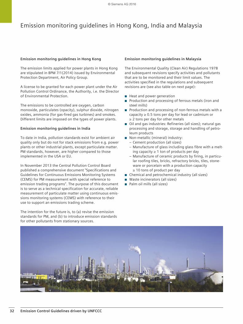
32 Emission Control Guidelines driven by UNFCCC
Emission monitoring guidelines in Hong Kong
The emission limits applied for power plants in Hong Kong are stipulated in BPM 7/1(2014) issued by Environmental Protection Department, Air Policy Group.
A license to be granted for each power plant under the Air Pollution Control Ordinance, the Authority, i.e. the Director of Environmental Protection.
The emissions to be controlled are oxygen, carbon monoxide, particulates (opacity), sulphur dioxide, nitrogen oxides, ammonia (for gas-fired gas turbines) and smokes. Different limits are imposed on the types of power plants.
Emission monitoring guidelines in India
To date in India, pollution standards exist for ambient air quality only but do not for stack emissions from e.g. power plants or other industrial plants, except particulate matter. PM standards, however, are higher compared to those implemented in the USA or EU.
In November 2013 the Central Pollution Control Board published a comprehensive document "Specifications and Guidelines for Continuous Emissions Monitoring Systems (CEMS) for PM measurement with special reference to emission trading programs". The purpose of this document is to serve as a technical specification for accurate, reliable measurement of particulate matter using continuous emis-sions monitoring systems (CEMS) with reference to their use to support an emissions trading scheme.
The intention for the future is, to (a) revise the emission standards for PM, and (b) to introduce emission standards for other pollutants from stationary sources.
Emission monitoring guidelines in Malaysia
The Environmental Quality (Clean Air) Regulations 1978 and subsequent revisions specify activities and pollutants that are to be monitored and their limit values. The activities specified in the regulations and subsequent revisions are (see also table on next page):
◾ Heat and power generation ◾ Production and processing of ferrous metals (iron and
steel mills) ◾ Production and processing of non-ferrous metals with a
capacity ≥ 0.5 tons per day for lead or cadmium or ≥ 2 tons per day for other metals
◾ Oil and gas industries: Refineries (all sizes); natural gas processing and storage, storage and handling of petro-leum products
◾ Non-metallic (mineral) industry: – Cement production (all sizes) – Manufacture of glass including glass fibre with a melt-ing capacity ≥ 1 ton of products per day
– Manufacture of ceramic products by firing, in particu-lar roofing tiles, bricks, refractory bricks, tiles, stone-ware or porcelain with a production capacity ≥ 10 tons of product per day
◾ Chemical and petrochemical industry (all sizes) ◾ Waste incinerators (all sizes) ◾ Palm oil mills (all sizes)
Emission monitoring guidelines in Hong Kong, India and Malaysia
© Siemens AG 2016
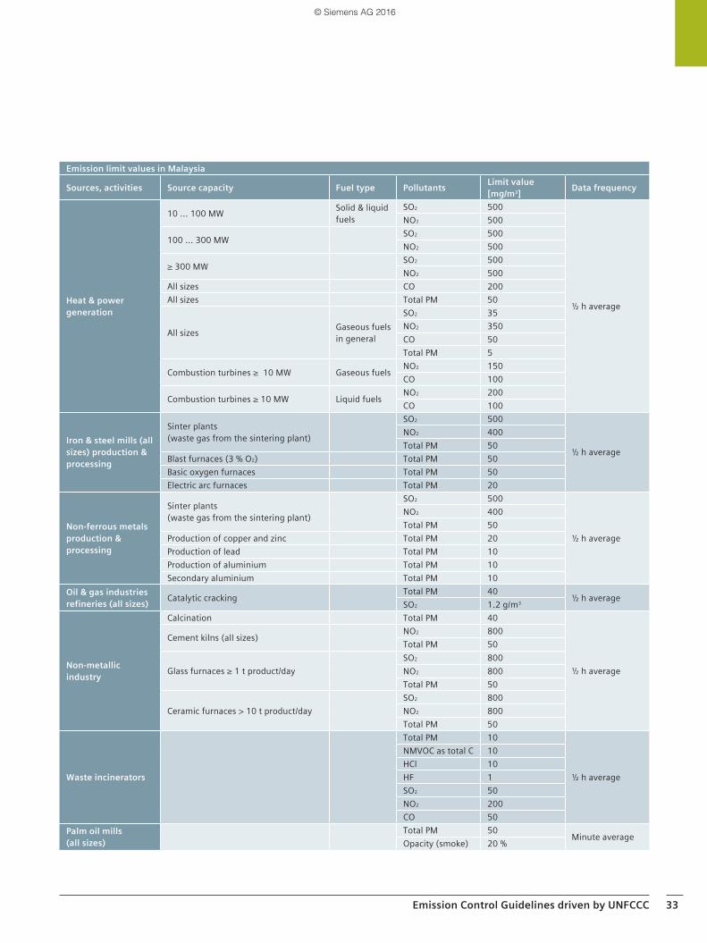
Emission Control Guidelines driven by UNFCCC 33
Emission limit values in Malaysia
Sources, activities Source capacity Fuel type Pollutants Limit value [mg/m3] Data frequency
Heat & power generation
10 ... 100 MW Solid & liquid fuels
SO2 500
½ h average
NO2 500
100 ... 300 MW SO2 500NO2 500
≥ 300 MW SO2 500NO2 500
All sizes CO 200All sizes Total PM 50
All sizes Gaseous fuels in general
SO2 35NO2 350CO 50Total PM 5
Combustion turbines ≥ 10 MW Gaseous fuels NO2 150CO 100
Combustion turbines ≥ 10 MW Liquid fuels NO2 200CO 100
Iron & steel mills (all sizes) production & processing
Sinter plants (waste gas from the sintering plant)
SO2 500
½ h average
NO2 400Total PM 50
Blast furnaces (3 % O2) Total PM 50Basic oxygen furnaces Total PM 50Electric arc furnaces Total PM 20
Non-ferrous metals production & processing
Sinter plants (waste gas from the sintering plant)
SO2 500
½ h average
NO2 400Total PM 50
Production of copper and zinc Total PM 20Production of lead Total PM 10Production of aluminium Total PM 10Secondary aluminium Total PM 10
Oil & gas industriesrefineries (all sizes) Catalytic cracking Total PM 40 ½ h averageSO2 1.2 g/m3
Non-metallic industry
Calcination Total PM 40
½ h average
Cement kilns (all sizes) NO2 800Total PM 50
Glass furnaces ≥ 1 t product/daySO2 800NO2 800Total PM 50
Ceramic furnaces > 10 t product/daySO2 800NO2 800Total PM 50
Waste incinerators
Total PM 10
½ h average
NMVOC as total C 10HCl 10HF 1SO2 50NO2 200CO 50
Palm oil mills (all sizes)
Total PM 50 Minute averageOpacity (smoke) 20 %
© Siemens AG 2016
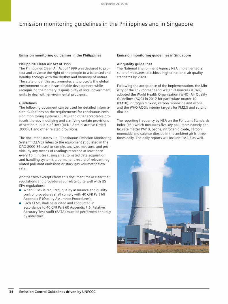
34 Emission Control Guidelines driven by UNFCCC
Emission monitoring guidelines in the Philippines and in Singapore
Emission monitoring guidelines in the Philippines
Philippine Clean Air Act of 1999 The Philippines Clean Air Act of 1999 was declared to pro-tect and advance the right of the people to a balanced and healthy ecology with the rhythm and harmony of nature. The state under this act promotes and protects the global environment to attain sustainable development while recognizing the primary responsibility of local government units to deal with environmental problems.
Guidelines The following document can be used for detailed informa-tion: Guidelines on the requirements for continuous emis-sion monitoring systems (CEMS) and other acceptable pro-tocols thereby modifying and clarifying certain provisions of section 5, rule X of DAO (DENR Administrative Order) 2000-81 and other related provisions.
The document states i. a. "Continuous Emission Monitoring System" (CEMS) refers to the equipment stipulated in the DAO 2000-81 used to sample, analyze, measure, and pro-vide, by any means of readings recorded at least once every 15 minutes (using an automated data acquisition and handling system), a permanent record of relevant reg-ulated pollutant emissions or stack gas volumetric flow rate.
Another two excerpts from this document make clear that regulations and procedures correlate quite well with US EPA regulations:
◾ When CEMS is required, quality assurance and quality control procedures shall comply with 40 CFR Part 60 Appendix F (Quality Assurance Procedures).
◾ Each CEMS shall be audited and conducted in accordance to 40 CFR Part 60 Appendix F.6. Relative Accuracy Test Audit (RATA) must be performed annually by industries.
Emission monitoring guidelines in Singapore
Air quality guidelinesThe National Environment Agency NEA implemented a suite of measures to achieve higher national air quality standards by 2020.
Following the acceptance of the implementation, the Min-istry of the Environment and Water Resources (MEWR) adopted the World Health Organisation (WHO) Air Quality Guidelines (AQG) in 2012 for particulate matter 10 (PM10), nitrogen dioxide, carbon monoxide and ozone, and the WHO AQG’s interim targets for PM2.5 and sulphur dioxide.
The reporting frequency by NEA on the Pollutant Standards Index (PSI) which measures five key pollutants namely par-ticulate matter PM10, ozone, nitrogen dioxide, carbon monoxide and sulphur dioxide in the ambient air is three times daily. The daily reports will include PM2.5 as well.
© Siemens AG 2016
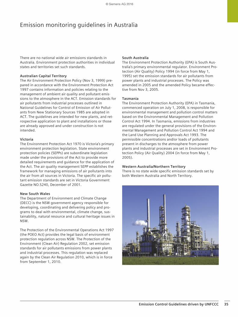
Emission Control Guidelines driven by UNFCCC 35
Emission monitoring guidelines in Australia
There are no national wide air emissions standards in Australia. Environment protection authorities in individual states and territories set such standards.
Australian Capital Territory The Air Environment Protection Policy (Nov 3, 1999) pre-pared in accordance with the Environment Protection Act 1997 contains information and policies relating to the management of ambient air quality and pollutant emis-sions to the atmosphere in the ACT. Emission standards for air pollutants from industrial processes outlined in National Guidelines for Control of Emission of Air Pollut-ants from New Stationary Sources 1985 are adopted in ACT. The guidelines are intended for new plants, and ret-rospective application to plant and installations or those are already approved and under construction is not intended.
Victoria The Environment Protection Act 1970 is Victoria’s primary environment protection legislation. State environment protection policies (SEPPs) are subordinate legislation made under the provisions of the Act to provide more detailed requirements and guidance for the application of the Act. The air quality management SEPP establishes the framework for managing emissions of air pollutants into the air from all sources in Victoria. The specific air pollu-tant emission standards are set in Victoria Government Gazette NO.S240, December of 2001.
New South Wales The Department of Environment and Climate Change (DECC) is the NSW government agency responsible for developing, coordinating and delivering policy and pro-grams to deal with environmental, climate change, sus-tainability, natural resource and cultural heritage issues in NSW.
The Protection of the Environmental Operations Act 1997 (the POEO Act) provides the legal basis of environment protection regulation across NSW. The Protection of the Environment (Clean Air) Regulation 2002, set emission standards for air pollutants emissions from power plants and industrial processes. This regulation was replaced again by the Clean Air Regulation 2010, which is in force from September 1, 2010.
South AustraliaThe Environment Protection Authority (EPA) is South Aus-tralia’s primary environmental regulator. Environment Pro-tection (Air Quality) Policy 1994 (in force from May 1, 1995) set the emission standards for air pollutants from power plants and industrial processes. The Policy was amended in 2005 and the amended Policy became effec-tive from Nov 3, 2005.
TasmaniaThe Environment Protection Authority (EPA) in Tasmania, commenced operation on July 1, 2008, is responsible for environmental management and pollution control matters based on the Environmental Management and Pollution Control Act 1994. In Tasmania, emissions from industries are regulated under the general provisions of the Environ-mental Management and Pollution Control Act 1994 and the Land Use Planning and Approvals Act 1993. The permissible concentrations and/or loads of pollutants present in discharges to the atmosphere from power plants and industrial processes are set in Environment Pro-tection Policy (Air Quality) 2004 (in force from May 1, 2005).
Western Australia/Northern TerritoryThere is no state wide specific emission standards set by both Western Australia and North Territory.
© Siemens AG 2016
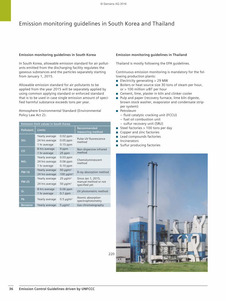
36 Emission Control Guidelines driven by UNFCCC
Emission monitoring guidelines in South Korea and Thailand
Emission monitoring guidelines in South Korea
In South Korea, allowable emission standard for air pollut-ants emitted from the discharging facility regulates the gaseous substances and the particles separately starting from January 1, 2015.
Allowable emission standard for air pollutants to be applied from the year 2015 will be separately applied by using common applying standard or enforced standard that is to be used in case single emission amount of speci-fied harmful substance exceeds tons per year.
Atmosphere Environmental Standard (Environmental Policy Law Act 2):
Emission monitoring guidelines in Thailand
Thailand is mostly following the EPA guidelines.
Continuous emission monitoring is mandatory for the fol-lowing production plants:
◾ Electricity generating > 29 MW ◾ Boilers or heat source size 30 tons of steam per hour,
or > 100 million u/BT per hour ◾ Cement, lime, plaster in kiln and clinker cooler ◾ Pulp and paper (recovery furnace, lime kiln digeste,
brown stock washer, evaporator and condensate strip-per system)
◾ Petroleum – fluid catalytic cracking unit (FCCU) – fuel oil combustion unit – sulfur recovery unit (SRU)
◾ Steel factories > 100 tons per day ◾ Copper and zinc factories ◾ Lead compounds factories ◾ Incinerators ◾ Sulfur producing factories
Emission limit values in South Korea
Pollutant Limits Recommended measuring method
SO2
Yearly average 0.02 ppmPulse UV fluorescence method24 hrs average 0.05 ppm
1 hr average 0.15 ppm
CO 8 hrs average 9 ppm Non dispersive infrared method1 hr average 25 ppm
NO2
Yearly average 0.03 ppmChemoluminescent method24 hrs average 0.06 ppm
1 hr average 0.10 ppm
PM-10 Yearly average 50 µg/m3
ß-ray absorption method24 hrs average 100 µg/m3
PM-25Yearly average 25 µg/m3 Since Jan 1, 2015,
manual method or not specified yet24 hrs average 50 µg/m3
O28 hrs average 0.06 ppm UV photometric method1 hr average 0.1 ppm
Pb Yearly average 0.5 µg/m3 Atomic absorption spectrophotometry
Benzene Yearly average 5 µg/m3 Gas chromatography
220
© Siemens AG 2016
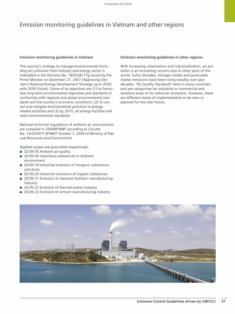
Emission Control Guidelines driven by UNFCCC 37
Emission monitoring guidelines in Vietnam and other regions
Emission monitoring guidelines in Vietnam
The country’s strategy to manage environmental (inclu-ding air) pollution from industry and energy sector is imbedded in the Decision No. 1855/QD-TTg issued by the Prime Minister on December 27, 2007 (Approving Viet-nam’s National Energy Development Strategy up to 2020, with 2050 Vision). Some of its objectives are (1) to formu-late long-term environmental objectives and standards in conformity with regional and global environmental stan-dards and the country’s economic conditions; (2) to con-trol and mitigate environmental pollution in energy-related activities and (3) by 2015, all energy facilities will reach environmental standards.
National technical regulations of ambient air and emission are compiled in 2009/BTNMT according to Circular No. 16/2009/TT-BTNMT October 7, 2009 of Ministry of Nat-ural Resources and Environment.
Applied scopes are prescribed respectively: ◾ QCVN 05 Ambient air quality ◾ QCVN 06 Hazardous substances in ambient
environment ◾ QCVN 19 Industrial emission of inorganic substances
and dusts ◾ QCVN 20 Industrial emissions of organic substances ◾ QCVN 21 Emission of chemical fertilizer manufacturing
industry ◾ QCVN 22 Emission of thermal power industry ◾ QCVN 23 Emission of cement manufacturing industry
Emission monitoring guidelines in other regions
With increasing urbanization and industrialization, air pol-lution is an increasing concern also in other parts of the world. Sulfur dioxides, nitrogen oxides and particulate matter emissions have been rising steadily over past decades. "Air Quality Standards" exist in many countries and are categorizes for industrial or commercial and sensitive areas or for vehicular emissions. However, there are different states of implementation to be seen or planned for the near future.
© Siemens AG 2016
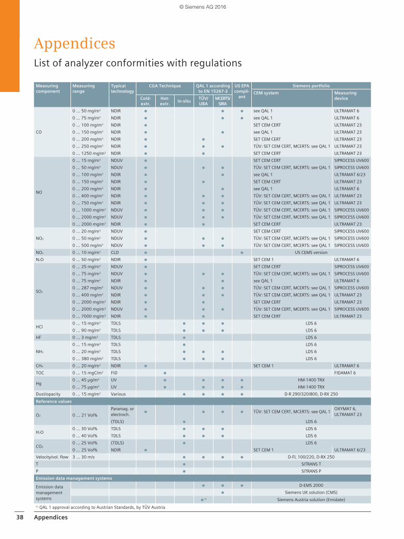
38 Appendices
AppendicesList of analyzer conformities with regulations
Measuring component
Measuring range
Typical technology
CGA Technique QAL 1 according to EN 15267-3
US EPA compli-
ant
Siemens portfolioCEM system Measuring
deviceCold-extr.
Hot-extr. In-situ TÜV/
UBAMCERTS/
SIRA
CO
0 ... 50 mg/m3 NDIR ● ● ● see QAL 1 ULTRAMAT 60 ... 75 mg/m3 NDIR ● ● ● see QAL 1 ULTRAMAT 60 ... 100 mg/m3 NDIR ● SET CEM CERT ULTRAMAT 230 ... 150 mg/m3 NDIR ● ● see QAL 1 ULTRAMAT 230 ... 200 mg/m3 NDIR ● ● SET CEM CERT ULTRAMAT 230 ... 250 mg/m3 NDIR ● ● ● TÜV: SET CEM CERT, MCERTS: see QAL 1 ULTRAMAT 230 ... 1250 mg/m3 NDIR ● ● SET CEM CERT ULTRAMAT 23
NO
0 ... 15 mg/m3 NDUV ● SET CEM CERT SIPROCESS UV6000 ... 50 mg/m3 NDUV ● ● ● TÜV: SET CEM CERT, MCERTS: see QAL 1 SIPROCESS UV6000 ... 100 mg/m3 NDIR ● ● see QAL 1 ULTRAMAT 6/230 ... 150 mg/m3 NDIR ● ● SET CEM CERT ULTRAMAT 230 ... 200 mg/m3 NDIR ● ● see QAL 1 ULTRAMAT 60 ... 400 mg/m3 NDIR ● ● ● TÜV: SET CEM CERT, MCERTS: see QAL 1 ULTRAMAT 230 … 750 mg/m3 NDIR ● ● ● TÜV: SET CEM CERT, MCERTS: see QAL 1 ULTRAMAT 230 ... 1000 mg/m3 NDUV ● ● ● TÜV: SET CEM CERT, MCERTS: see QAL 1 SIPROCESS UV6000 ... 2000 mg/m3 NDUV ● ● ● TÜV: SET CEM CERT, MCERTS: see QAL 1 SIPROCESS UV6000 ... 2000 mg/m3 NDIR ● ● SET CEM CERT ULTRAMAT 23
NO2
0 ... 20 mg/m3 NDUV ● SET CEM CERT SIPROCESS UV6000 ... 50 mg/m3 NDUV ● ● ● TÜV: SET CEM CERT, MCERTS: see QAL 1 SIPROCESS UV6000 ... 500 mg/m3 NDUV ● ● ● TÜV: SET CEM CERT, MCERTS: see QAL 1 SIPROCESS UV600
NOx 0 ... 10 mg/m3 CLD ● ● US CEMS versionN2O 0 ... 50 mg/m3 NDIR ● SET CEM 1 ULTRAMAT 6
SO2
0 ... 25 mg/m3 NDUV ● SET CEM CERT SIPROCESS UV6000 ... 75 mg/m3 NDUV ● ● ● TÜV: SET CEM CERT, MCERTS: see QAL 1 SIPROCESS UV6000 ... 75 mg/m3 NDIR ● ● see QAL 1 ULTRAMAT 60 ... 287 mg/m3 NDUV ● ● ● TÜV: SET CEM CERT, MCERTS: see QAL 1 SIPROCESS UV6000 ... 400 mg/m3 NDIR ● ● ● TÜV: SET CEM CERT, MCERTS: see QAL 1 ULTRAMAT 230 ... 2000 mg/m3 NDIR ● ● SET CEM CERT ULTRAMAT 230 ... 2000 mg/m3 NDUV ● ● ● TÜV: SET CEM CERT, MCERTS: see QAL 1 SIPROCESS UV6000 ... 7000 mg/m3 NDIR ● ● SET CEM CERT ULTRAMAT 23
HCl0 ... 15 mg/m3 TDLS ● ● ● LDS 60 ... 90 mg/m3 TDLS ● ● ● LDS 6
HF 0 ... 3 mg/m3 TDLS ● LDS 6
NH3
0 ... 15 mg/m3 TDLS ● LDS 60 ... 20 mg/m3 TDLS ● ● ● LDS 60 ... 380 mg/m3 TDLS ● ● ● LDS 6
CH4 0 ... 20 mg/m3 NDIR ● SET CEM 1 ULTRAMAT 6TOC 0 ... 15 mgC/m3 FID ● FIDAMAT 6
Hg0 ... 45 µg/m3 UV ● ● ● ● HM-1400 TRX0 ... 75 µg/m3 UV ● ● ● ● HM-1400 TRX
Dust/opacity 0 ... 15 mg/m3 Various ● ● ● ● D-R 290/320/800, D-RX 250Reference values
O2 0 ... 21 Vol%Paramag. or electroch. ● ● ● ● TÜV: SET CEM CERT, MCERTS: see QAL 1 OXYMAT 6,
ULTRAMAT 23 (TDLS) ● LDS 6
H2O0 ... 30 Vol% TDLS ● ● ● LDS 60 ... 40 Vol% TDLS ● ● ● LDS 6
CO20 ... 25 Vol% (TDLS) ● LDS 60 ... 25 Vol% NDIR ● SET CEM 1 ULTRAMAT 6/23
Velocity/vol. flow 3 ... 30 m/s ● ● ● ● D-FL 100/220, D-RX 250T ● SITRANS TP ● SITRANS PEmission data management systems
Emission data management systems
● ● ● D-EMS 2000● Siemens UK solution (CMS)
●1) Siemens Austria solution (Emidate)1) QAL 1 approval according to Austrian Standards, by TÜV Austria
© Siemens AG 2016
Appendices 39
Application questionnaires for CEM applications and other services for gas analysis from Siemens Process Analytics
Application questionnaires for CEM applications
Siemens Process Analytics has extensive experience in planning, engineering and manufacturing of analytical sys-tems including CEMS. From single standard analyzer to customized systems, we can provide a solution that will meet your specific requirements.
To enable us to offer appropriate solutions according to your specific requirements, we need comprehensive infor-mation about your application, process conditions and especially the gas matrix regarding all present gas compo-nents – measuring components as well as perhaps interfer-ing components. To make this communication as conve-nient and efficient as possible, we have prepared a series of questionnaires for our products and different applica-tion sets. Please answer the questions as completely as possible. We will review your answers, requirements and comments and will contact you for further actions.
Application questionnaires may be found for download on our process analytics website:www.siemens.com/processanalytics
Other services for gas analysis from Siemens Process Analytics
Siemens Process Analytics offers a comprehensive range of innovative and proven products, systems, and services for process and quality optimization in diverse applications.
Some examples
Process efficiencyUse of in-situ laser gas analyzer can improve your environ-mental performance and reduce operating costs by careful dosing control of consumable media such as lime or urea/ammonium hydroxide on acid gas scrubbing or SCR/SNCR DeNOx process.
Combustion controlUse of laser for oxygen and/or CO trim on combustion plant can improve fuel use efficiency by tighter control of air demand.
Syngas calorific valueOptimize your produced gas quality, yield and financial return by monitoring the energy value by use of micro pro-cess chromatography.
Biogas production monitoringOur "Set BGA" standard analysis package is an ideal tool to optimize biogas yield and quality from anaerobic digestion or land fill process.
Maritime emissions monitoringUse of ULTRAMAT 23 and ULTRAMAT 6 on ships for emis-sion monitoring according to IMO (International Maritime Organization) environmental standards.
Securing the success of your business with Siemens industry servicesIncreasing demands make it ever more important that industrial plants operate at highest productivity and effi-ciency levels. The Siemens industry service portfolio helps companies secure the decisive advantage over the competition.
Whether it’s production or process industry - in view of ris-ing cost pressure, growing energy costs, and increasingly stringent environmental regulations, services for industry are a crucial competitive factor in manufacturing as well as in process industries. All over the world Siemens supports its customers with product, system, and application-related services throughout the entire life cycle of a plant. Right from the earliest stages of planning, engineering, and building all the way to operation and modernization, these services enable customers to benefit from the Siemens experts’ unique technological and product know-ledge and industry expertise. Thus downtimes are reduced and the utilization of resources is optimized. The bottom line: increased plant productivity, flexibility, and efficiency, plus reduced overall costs.
◾ Online support ◾ Technical support ◾ Spare parts ◾ Repair services ◾ Field services ◾ Training ◾ Service contracts
© Siemens AG 2016
Get more informationwww.siemens.com/processanalytics
Service and Support:www.siemens.com/automation/service&support
Information and Ordering Platform in the Internet:www.siemens.com/industrymall
Siemens AGProcess Industries and DrivesProcess Analytics76181 KARLSRUHEGERMANY
© Siemens AG 2016Subject to change without prior noticeArticle No. E86060-A3501-A101-A5-7600W-FPN6Z-PD-PA285 / Dispo 27902BR 0916 1.0 GUT 40 EnPrinted in Germany
The information provided in this brochure contains merely general descriptions or characteristics of performance which in case of actual use do not always apply as described or which may change as a result of further development of the products. An obligation to provide the respective characteristics shall only exist if expressly agreed in the terms of contract. Availability and technical specifications are subject to change without notice.
All product designations may be trademarks or product names of Siemens AG or supplier companies whose use by third parties for their own purposes could violate the rights of the owners.
Security informationSiemens provides products and solutions with industrial security functions that support the secure operation of plants, systems, machines and networks.
In order to protect plants, systems, machines and networks against cyber threats, it is necessary to implement – and continuously maintain – a holistic, state-of-the-art indus-trial security concept. Siemens’ products and solutions only form one element of such a concept.
Customer is responsible to prevent unauthorized access to its plants, systems, machines and networks. Systems, machines and components should only be connected to the enterprise network or the internet if and to the extent necessary and with appropriate security measures (e.g. use of firewalls and network segmentation) in place.
Additionally, Siemens’ guidance on appropriate security measures should be taken into account. For more informa-tion about industrial security, please visit http://www.siemens.com/industrialsecurity.
Siemens’ products and solutions undergo continuous development to make them more secure. Siemens strongly recommends to apply product updates as soon as available and to always use the latest product versions. Use of product versions that are no longer supported, and failure to apply latest updates may increase customer’s exposure to cyber threats.
To stay informed about product updates, subscribe to the Siemens Industrial Security RSS Feed under http://www.siemens.com/industrialsecurity.
© Siemens AG 2016


