International OPEN ACCESS Journal Of M ode r n En ginee ri ng Re s e arch (I JM ER) | IJMER| ISSN: 2249–6645 | www.ijmer.com | Vol. 5 | Iss. 7 | July 2015 | 26 |Process Design and Development of Electromagnetic Shearing Machine SagarP.Kulkarni 1 , Shailesh B.Wahulkar2 , Swapnil M.Yeole 3 , Anant Kumar4 , Mangesh P.Naik5 , Sushil D.Yeole 6 1 Process Executive, Sutherland Global Services, Mumbai, India. 2 Process Executive, Infosys Ltd, Pune, India. 3 Mechanical Engineer, Tata Toyo Radiator Ltd., Pune, India. 4 MSc Student, UniversityCollege Dublin, Dublin, Irelan d. 5 MS(Industrial Engineering), Western Michigan University, MI, USA. 6Assistant Professor, Department of Mechanical Engineering, MGM Polytechnic, Aurangabad, India. I.INTRODUCTIONIn recent times of automation world and competitive market there is a huge scope for introducing different techniques for minimizing the human efforts as well as different parameters like time and cost. The project was carried in a company which is located in Nashik, India and the company faced manyproblems because of using hand operated shearing machine. Also the company used to face the some other problems which stopped them from achieving their goals and there was h uge deviation between actual and planned output. The problems faced are stated below: - Actual cycle time is more than the standard time required to complete the wh ole process. - Accuracy achiev ed was very less. - Surface finish w as not satisfactory. - Because of less s urface finish the process was not su itable for mass production. - The operator should be skilled enough to produce the required dimensions. Hence to overcome all the problems stated above, electromagnetic type shearing machine is the best solution which can give us the expected result in right time and at right cost. There could be a various types of automatic machines such as hydraulic, pneumatic or electromagnetic type. But in case of hydraulic and pneumatic machines there are more power losses while working than in electromagnetic type. So we started with first understanding the basics and then building a prototype which we can test and then see that it gives the results as per expectations or not. Also the different factors such as cost and reliability were taken into consideration because if the cost is too high th en it may be not considered as th e best solution even if it is reliable. II.UNDERSTANDING PRINCIPLE OF ELECTROMAGNETAn electromagnet is a “temporary magnet” - the magnetic field only exists when electric current flows, the magnetic fields disappear when the current ceases. Electromagnets are used to lift heavy masses of magnetic material and to attract movable magnetic parts of electric devices, such as solenoids, relays, and clutches. Electromagnets are the devices in which the magnetism in the cores can be turned on or off. An electromagnet starts with a direct AC supply of power reduced voltage with the help of step-down Transformer (or some other source of power) and a wire. When we start AC supply transformer it reduces 230v to 48v which is required and then current produces magnetic force. When an AC current flows through the ABSTRACT: In ancient time there was need of developing some machinery equipment which will lead toreduce the human efforts. Sothis resulted in development of various hand operated machines. These machines fulfilled the basic production needs through lesser human efforts. But in today’scompetitive world, the company has to always implement new strategies which will help them to linger in the market and generally the lowest cost producer always wins.As the process of doing business gets more complex and cumbersome, technology and automation become vital resources for the success and continued growth of organization.So with this view shearing machine of a new type i.e. electromagnetic shearing machine was fabricated to overcome all the problems faced by the company in which this project was done. The results obtained after testing the newlyfabricated machine shown that the performance of machine is better than manual machine and it can also perform other functions with high accuracy and at low cost. Keywords:Electromagnetic shearing machine, Automation.
Transcript
8/20/2019 Process Design and Development of Electromagnetic Shearing Machine
5 MS(Industrial Engineering), Western Michigan University, MI, USA.
6 Assistant Professor, Department of Mechanical Engineering, MGM Polytechnic, Aurangabad, India.
I.
INTRODUCTION In recent times of automation world and competitive market there is a huge scope for introducingdifferent techniques for minimizing the human efforts as well as different parameters like time and cost. The
project was carried in a company which is located in Nashik, India and the company faced manyproblems because of using hand operated shearing machine. Also the company used to face the some other problemswhich stopped them from achieving their goals and there was huge deviation between actual and planned output.The problems faced are stated below:- Actual cycle time is more than the standard time required to complete the whole process.- Accuracy achieved was very less.- Surface finish was not satisfactory.- Because of less surface finish the process was not suitable for mass production.- The operator should be skilled enough to produce the required dimensions.
Hence to overcome all the problems stated above, electromagnetic type shearing machine is the best solution
which can give us the expected result in right time and at right cost. There could be a various types of automaticmachines such as hydraulic, pneumatic or electromagnetic type. But in case of hydraulic and pneumaticmachines there are more power losses while working than in electromagnetic type. So we started with firstunderstanding the basics and then building a prototype which we can test and then see that it gives the results as
per expectations or not. Also the different factors such as cost and reliability were taken into consideration because if the cost is too high then it may be not considered as the best solution even if it is reliable.
II. UNDERSTANDING PRINCIPLE OF ELECTROMAGNET An electromagnet is a “temporary magnet” - the magnetic field only exists when electric current flows,
the magnetic fields disappear when the current ceases. Electromagnets are used to lift heavy masses of magneticmaterial and to attract movable magnetic parts of electric devices, such as solenoids, relays, and clutches.Electromagnets are the devices in which the magnetism in the cores can be turned on or off.
An electromagnet starts with a direct AC supply of power reduced voltage with the help of step-down
Transformer (or some other source of power) and a wire. When we start AC supply transformer it reduces 230vto 48v which is required and then current produces magnetic force. When an AC current flows through the
ABSTRACT: In ancient time there was need of developing some machinery equipment which will lead
toreduce the human efforts. Sothis resulted in development of various hand operated machines. These
machines fulfilled the basic production needs through lesser human efforts. But in today’scompetitive
world, the company has to always implement new strategies which will help them to linger in the market
and generally the lowest cost producer always wins.As the process of doing business gets more complex
and cumbersome, technology and automation become vital resources for the success and continued growth
of organization.So with this view shearing machine of a new type i.e. electromagnetic shearing machine
was fabricated to overcome all the problems faced by the company in which this project was done. The
results obtained after testing the newlyfabricated machine shown that the performance of machine is betterthan manual machine and it can also perform other functions with high accuracy and at low cost.
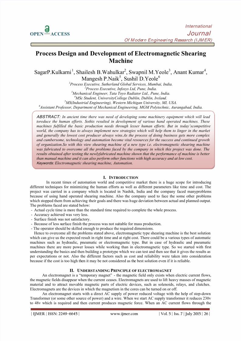
conductor, a magnetic flux is generated around the conductor. The extent of magnetic flux extends up to the areaof magnetic field. The flux density is measured by the unit called tesla. It is the ratio of the flux in any crosssection to the area of that cross section, being taken normal to the direction of flux. [12]
Fig.1 Schematic of Electromagnet [3]Fig.2 Working of Electromagnet [3]
The basic idea behind an electromagnet is extremely simple. By running electric current through awire, you can create a magnetic field. Maxwell is the C.G.S unit of the magnetic field and it is measured asWeber in M.K.S. system. By using this simple principle, one can create all sorts of things including motors,solenoids, read/write heads for hard disk tape drives and so on. In this article, we will see exactly howelectromagnet works. We will also have to try several experiments with electromagnets that we create our self.An electromagnet is a “temporary magnet” - the magnetic field only exits when electric current starts flowing.
If we look at a battery, say at a normal D-cell from a flashlight, you can see that there are two ends.One marked plus (+) and the other marked minus (-) Electrons collect at the negative end of the battery, and, ifyou let them, they will gladly flow to the positive end. The way you “let them” flow is with a wire. If we attacha wire directly between the positive and negative terminals of a D-cell two things will happen:- Electrons will flow from the negative side of the battery to the positive side as fast as they can.
- A small magnetic field is generated in the wire. It is this small magnetic field that is the basis of anelectromagnet.
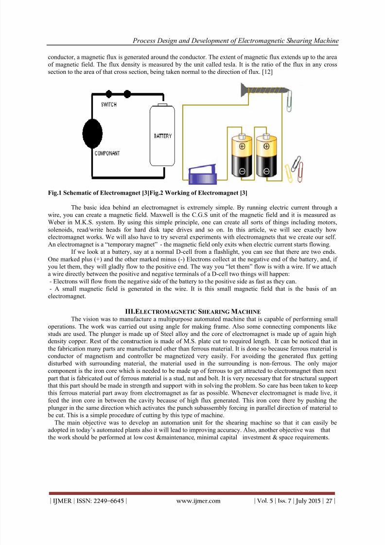
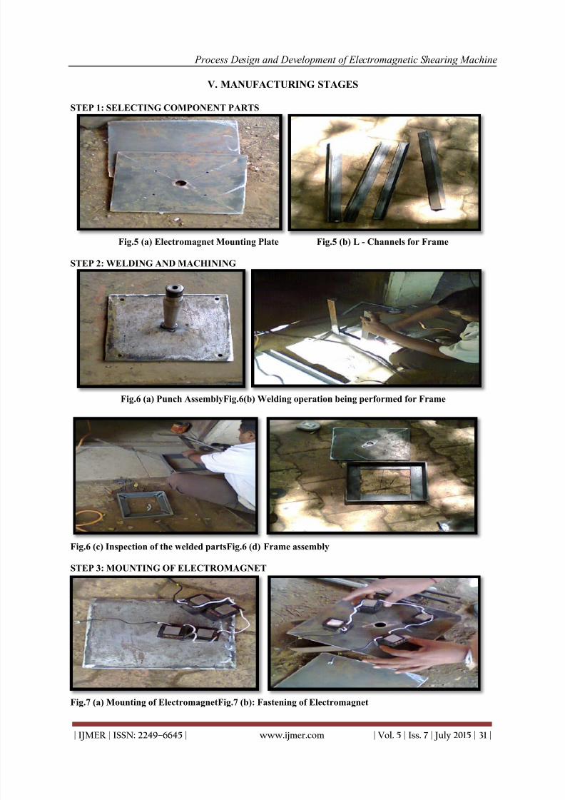
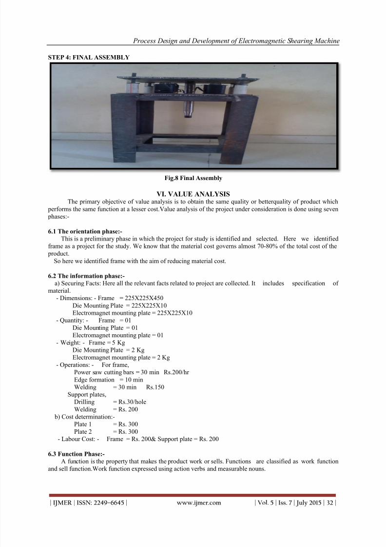
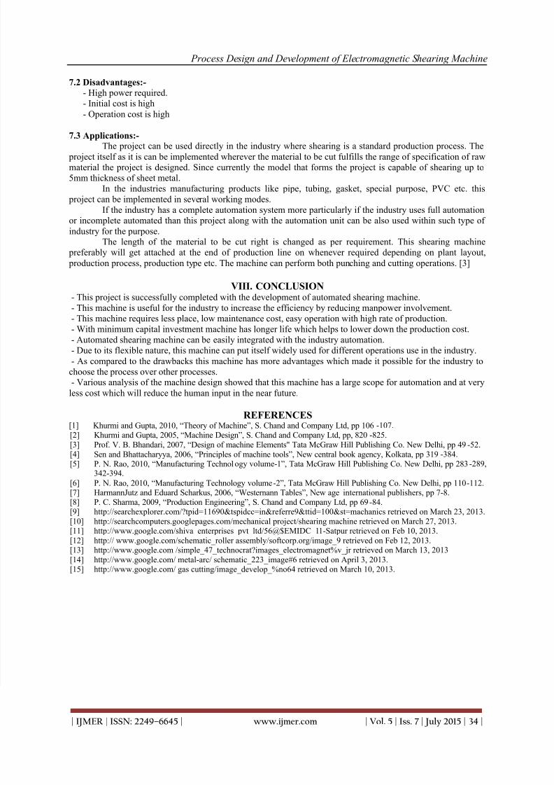
III.ELECTROMAGNETIC SHEARING MACHINE The vision was to manufacture a multipurpose automated machine that is capable of performing small
operations. The work was carried out using angle for making frame. Also some connecting components likestuds are used. The plunger is made up of Steel alloy and the core of electromagnet is made up of again highdensity copper. Rest of the construction is made of M.S. plate cut to required length. It can be noticed that inthe fabrication many parts are manufactured other than ferrous material. It is done so because ferrous material isconductor of magnetism and controller be magnetized very easily. For avoiding the generated flux gettingdisturbed with surrounding material, the material used in the surrounding is non-ferrous. The only majorcomponent is the iron core which is needed to be made up of ferrous to get attracted to electromagnet then next
part that is fabricated out of ferrous material is a stud, nut and bolt. It is very necessary that for structural supportthat this part should be made in strength and support with in solving the problem. So care has been taken to keepthis ferrous material part away from electromagnet as far as possible. Whenever electromagnet is made live, itfeed the iron core in between the cavity because of high flux generated. This iron core there by pushing the
plunger in the same direction which activates the punch subassembly forcing in parallel direction of material to be cut. This is a simple procedure of cutting by this type of machine.
The main objective was to develop an automation unit for the shearing machine so that it can easily beadopted in today’s automated plants also it will lead to improving accuracy. Also, another objective was thatthe work should be performed at low cost &maintenance, minimal capital investment & space requirements.
8/20/2019 Process Design and Development of Electromagnetic Shearing Machine
Fig.3 Schematic Diagram of Electromagnetic Machine [12]
IV. CALCULATION OF ELECTROMAGNETIC FORCE If the magnetic field is confined within a high permeability material like certain steel alloys, the maximum
force is given by:F=(B^2 A)/(2μ _0 )
Where:F is the force in Newton, B is the magnetic field in tesla, A is the area of the pole faces in square meters &μo isthe permeability of free space.In the case of free space (air),
μ _0=4π〖10〗^(-7) Hm^(-1) ,
In a closed magnetic circuit:F=μ NI/LWhere:
N is the number of turns of wire around the electromagnet, I is the current in amperes &L is the length of themagnetic circuit.
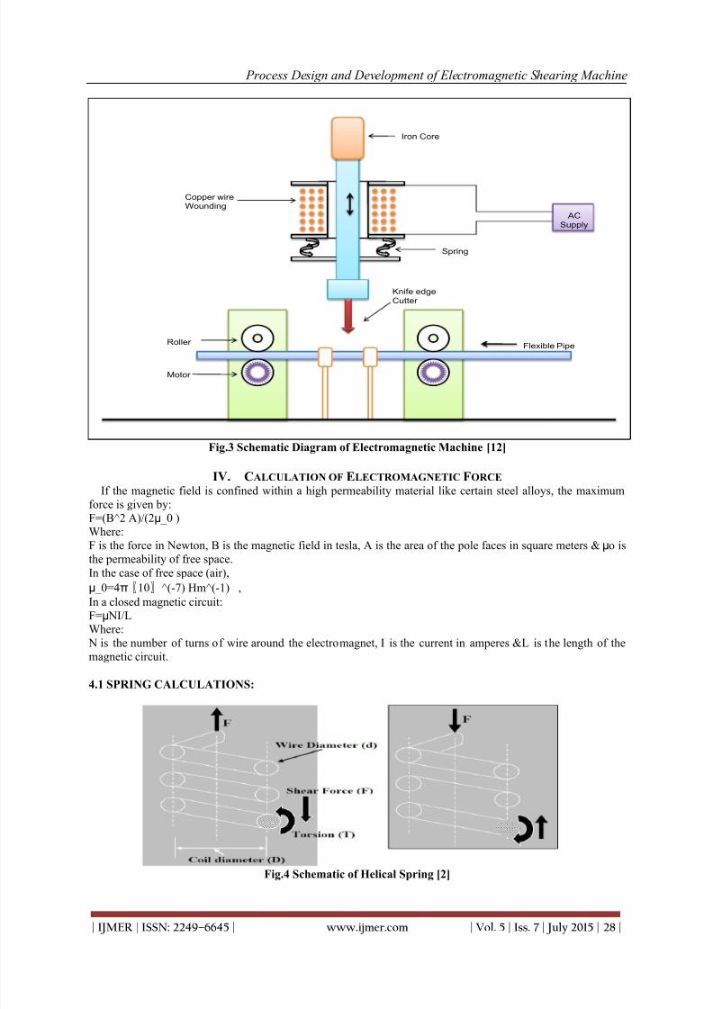
4.1 SPRING CALCULATIONS:
Fig.4 Schematic of Helical Spring [2]
8/20/2019 Process Design and Development of Electromagnetic Shearing Machine
4.2 METALLURGICAL SPECIFICATIONS:The materials used in this project are detailed as follows:- FERROUS MATERIALS:
a) Low Carbon steel - EN – 1 to EN – 3Carbon – 0.05% to 0.08%Tensile strength – 420/550 MPAYield strength – 275/350 MPA
b) Mild steel- EN – 4 to EN – 6Carbon – 0.15% to 0.35%Tensile strength – 1200/1420MPAYield strength – 750/1170 MPA
- WROUGHT IRON:Wrought iron is the purest iron which contains at least 99.5% of iron, but may contain up to 99.0% iron. The
wrought iron is produced from pig iron by remoulding it in the pudding furnace. The molten metal free fromimpurities is removed from the furnace as a pasty mass of iron and slag. The balls of pasty mass, each about 45to 65 kg in weight, are formed. These balls are mechanically worked both to squeeze out the slag and to form itinto some commercial shape.
The typical composition of a wrought is Carbon = 0.020%, Silicon = 0.120%, Sulphur = 0.018%,Phosphorous = 0.020%, Slag = 0.070% and the remaining is iron.
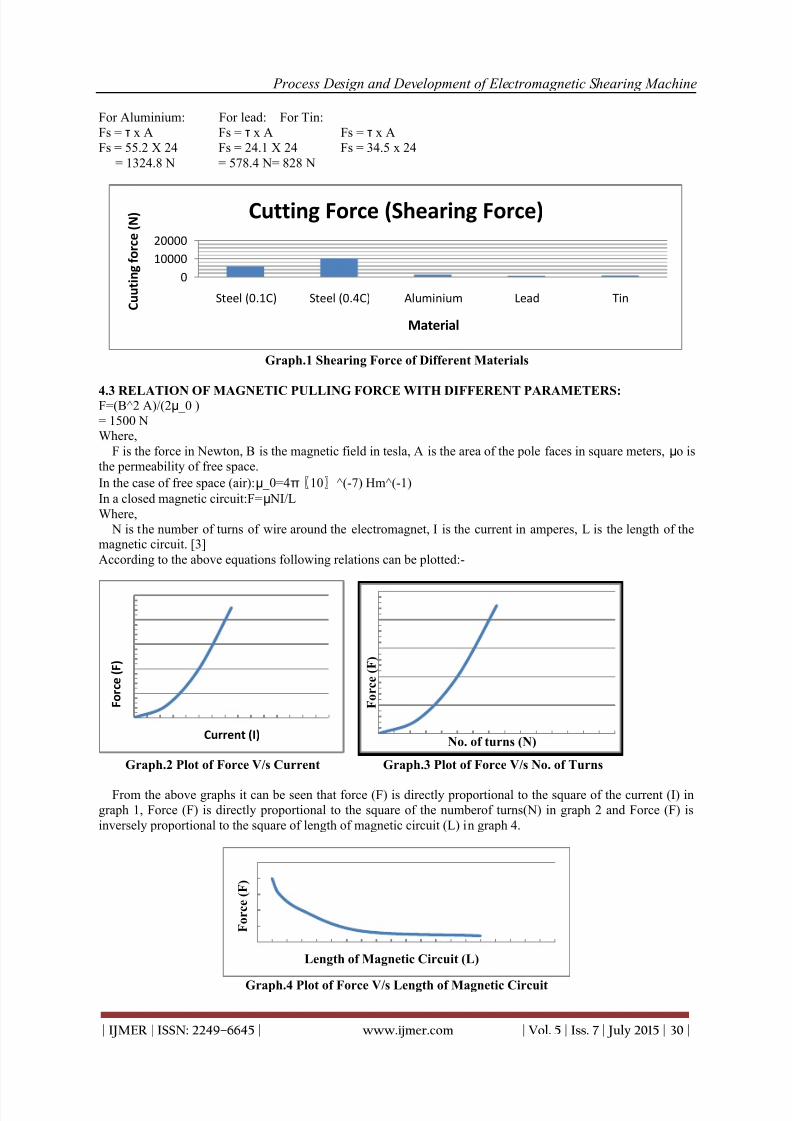
4.2.1 SHEARING FORCE CALCULATION FOR DIFFERENT MATERIALS:-
The process of shearing is similar to the process of cutting, which exhibits such a phenomenon of work piece separation because of the destruction behavior. The working faces of the punch or die are ground off sothat they don’t remain parallel to the horizontal plane but are inclined to it. This angle of inclination is calledshear. The metal is brought to the plastic stage by pressing the strip between two shearing blades so that fractureis initiated at the cutting points. The fractures on either side of the strip further progressing downwards with the
movement of upper shear, finally results in the separation of the slug from the parent strip. [8]The metal under shear is subjected to both compressive and tensile stresses. In an ideal shearing
operation, the upper shear pushes the metal to a depth equal to about one-third of its thickness. Because of pushing of the material into a lower shear, the area of cross section of the metal between the cutting edge of theshears decreases and causes the initiation of the fracture. This portion of the shear which is forced into lowershear is highly burnished and would appear as a bright band around the blank lower portion. The fractures whichare initiated at both the cutting points would progress further with the movement of the upper shear and if theclearance is sufficient, they would meet thus completing the shearing action. [5]Formula for shear force calculation:-For Steel (0.10 C) (For cold worked steel 0.10c)For Steel (0.40C)Fs = τ x A Fs = 7116 NFs = τ x AFs = 241.3 X 24Fs = 427.5 x 24= 5791.2 N= 10206 N
8/20/2019 Process Design and Development of Electromagnetic Shearing Machine
For Aluminium: For lead: For Tin:Fs = τ x A Fs = τ x A Fs = τ x AFs = 55.2 X 24 Fs = 24.1 X 24 Fs = 34.5 x 24
= 1324.8 N = 578.4 N= 828 N
Graph.1 Shearing Force of Different Materials
4.3 RELATION OF MAGNETIC PULLING FORCE WITH DIFFERENT PARAMETERS:F=(B^2 A)/(2μ _0 )= 1500 NWhere,
F is the force in Newton, B is the magnetic field in tesla, A is the area of the pole faces in square meters, μo isthe permeability of free space.
In the case of free space (air):μ _0=4π〖10〗^(-7) Hm^(-1)
In a closed magnetic circuit:F=μ NI/LWhere,
N is the number of turns of wire around the electromagnet, I is the current in amperes, L is the length of themagnetic circuit. [3]According to the above equations following relations can be plotted:-
Graph.2 Plot of Force V/s Current Graph.3 Plot of Force V/s No. of Turns
From the above graphs it can be seen that force (F) is directly proportional to the square of the current (I) ingraph 1, Force (F) is directly proportional to the square of the numberof turns(N) in graph 2 and Force (F) isinversely proportional to the square of length of magnetic circuit (L) in graph 4.
Graph.4 Plot of Force V/s Length of Magnetic Circuit
0
10000
20000
Steel (0.1C) Steel (0.4C) Aluminium Lead Tin C u u t i n g f o r c e ( N )
Material
Cutting Force (Shearing Force)
F o r c e ( F )
No. of turns (N)
F o r c e ( F )
Length of Magnetic Circuit (L)
F o r c e ( F )
Current (I)
8/20/2019 Process Design and Development of Electromagnetic Shearing Machine
6.4 The Creative phase:- After analysis, it was found that when round bars are used which are welded to support plates to the top
as well as bottom side, requires more material for strength and rigidity. Due to that unnecessary material costwas increasing.
6.5 Evaluation phase:-After creative phase the problems are quite clear. The reasons for these problems were found out in the
evaluation phase and then evaluated. It was found that the frame of round bars causing the increase in materialcost. So it is decided not to use a round bar over a structure, rather it is replaced by L-shaped channels. Now thematerial cost will get reduced keeping function same. Thus problem is overcomeby saving material.
Now cost will be:-- Operations: - For frame,
Power saw cutting bars = 30 min Rs.200/hrEdge formation = 10 minWelding = 30 min Rs.150
Support plates,Drilling = Rs.30/holeWelding = Rs. 200
-Capital investment is low.- Running cost is low.- Low maintenance.- Cutting speed is high.- No need of skilled labour.- Rate of cutting is high.- Complexity is low.
- Periodic maintenance not required.- Cost of spares is low.
Description of an item Old cost (Rs.) New cost (Rs.) Saving (Rs.)
Frame + support plate 2000 1600 400
8/20/2019 Process Design and Development of Electromagnetic Shearing Machine
- High power required.- Initial cost is high- Operation cost is high
7.3 Applications:-The project can be used directly in the industry where shearing is a standard production process. The
project itself as it is can be implemented wherever the material to be cut fulfills the range of specification of rawmaterial the project is designed. Since currently the model that forms the project is capable of shearing up to5mm thickness of sheet metal.
In the industries manufacturing products like pipe, tubing, gasket, special purpose, PVC etc. this project can be implemented in several working modes.
If the industry has a complete automation system more particularly if the industry uses full automationor incomplete automated than this project along with the automation unit can be also used within such type ofindustry for the purpose.
The length of the material to be cut right is changed as per requirement. This shearing machine preferably will get attached at the end of production line on whenever required depending on plant layout, production process, production type etc. The machine can perform both punching and cutting operations. [3]
VIII. CONCLUSION- This project is successfully completed with the development of automated shearing machine.- This machine is useful for the industry to increase the efficiency by reducing manpower involvement.- This machine requires less place, low maintenance cost, easy operation with high rate of production.- With minimum capital investment machine has longer life which helps to lower down the production cost.- Automated shearing machine can be easily integrated with the industry automation.- Due to its flexible nature, this machine can put itself widely used for different operations use in the industry.- As compared to the drawbacks this machine has more advantages which made it possible for the industry to
choose the process over other processes.- Various analysis of the machine design showed that this machine has a large scope for automation and at very
less cost which will reduce the human input in the near future.
REFERENCES[1]
Khurmi and Gupta, 2010, “Theory of Machine”, S. Chand and Company Ltd, pp 106 -107.[2]
Khurmi and Gupta, 2005, “Machine Design”, S. Chand and Company Ltd, pp, 820 -825.[3]
Prof. V. B. Bhandari, 2007, “Design of machine Elements" Tata McGraw Hill Publishing Co. New Delhi, pp 49 -52.[4]
Sen and Bhattacharyya, 2006, “Principles of machine tools”, New central book agency, Kolkata, pp 319-384.[5]
P. N. Rao, 2010, “Manufacturing Technology volume-1”, Tata McGraw Hill Publishing Co. New Delhi, pp 283 -289,342-394.
[6] P. N. Rao, 2010, “Manufacturing Technology volume-2”, Tata McGraw Hill Publishing Co. New Delhi, pp 110-112.[7] HarmannJutz and Eduard Scharkus, 2006, “Westernann Tables”, New age international publishers, pp 7-8.[8]
P. C. Sharma, 2009, “Production Engineering”, S. Chand and Company Ltd, pp 69-84.[9]
http://searchexplorer.com/?tpid=11690&tspidcc=in&referre9&ttid=100&st=machanics retrieved on March 23, 2013.[10]
http://searchcomputers.googlepages.com/mechanical project/shearing machine retrieved on March 27, 2013.[11]
http://www.google.com/shiva_enterprises_pvt_ltd/56@$EMIDC_11-Satpur retrieved on Feb 10, 2013.[12] http:// www.google.com/schematic_roller assembly/softcorp.org/image_9 retrieved on Feb 12, 2013.
[13]
http://www.google.com /simple_47_technocrat?images_electromagnet%v_jr retrieved on March 13, 2013[14]
http://www.google.com/ metal-arc/ schematic_223_image#6 retrieved on April 3, 2013.[15]
http://www.google.com/ gas cutting/image_develop_%no64 retrieved on March 10, 2013.