The sensor is comprised of an turbine vane, which is set in rotationby the flow speed. The rotation is proportional to the flow value pertime.
All converters which accept a frequency signal as an input signal(see frequency range of the various areas) can be combined with aelectronic evaluation. See also device overview.
NoteHowever, it must be ensured that the flow sensor is always filledwith medium and remains filled. Any arbitrary installation position ispossible, however, the best-possible bleeding position should beselected (flow from left to right or from bottom to top).
Attention: Air bubbles have a significant, negative impact of themeasurement results!
The valve should always be installed after the sensor for emptyingprocesses. Factor in a start-up time (approx. 0.5 sec) and an after-run time (approx. 3 sec).
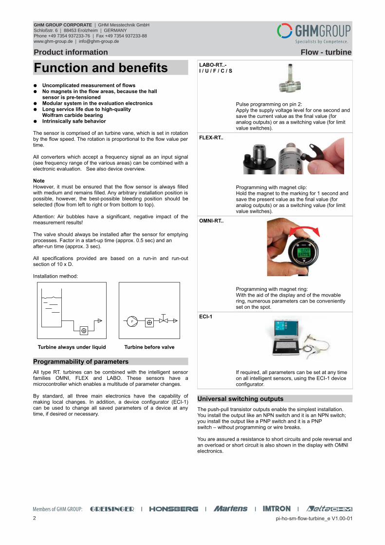
All specifications provided are based on a run-in and run-outsection of 10 x D. Installation method:
Turbine always under liquid Turbine before valve
Programmability of parameters
All type RT. turbines can be combined with the intelligent sensorfamilies OMNI, FLEX and LABO. These sensors have amicrocontroller which enables a multitude of parameter changes.
By standard, all three main electronics have the capability ofmaking local changes. In addition, a device configurator (ECI-1)can be used to change all saved parameters of a device at anytime, if desired or necessary.
LABO-RT..- I / U / F / C / S
Pulse programming on pin 2:Apply the supply voltage level for one second andsave the current value as the final value (for analog outputs) or as a switching value (for limit value switches).
FLEX-RT..
Programming with magnet clip:Hold the magnet to the marking for 1 second and save the present value as the final value (for analog outputs) or as a switching value (for limit value switches).
OMNI-RT..
Programming with magnet ring:With the aid of the display and of the movable ring, numerous parameters can be conveniently set on the spot.
ECI-1
If required, all parameters can be set at any time on all intelligent sensors, using the ECI-1 device configurator.
Universal switching outputs
The push-pull transistor outputs enable the simplest installation. You install the output like an NPN switch and it is an NPN switch; you install the output like a PNP switch and it is a PNP switch – without programming or wire breaks.
You are assured a resistance to short circuits and pole reversal andan overload or short circuit is also shown in the display with OMNI electronics.
GHM Messtechnik GmbH – Location HonsbergTenter Weg 2-8 42897 Remscheid Germany Fon +49-2191-9672-0 Fax -40www.ghm-messtechnik.de [email protected]
Product Information Sensors and Instrumentation
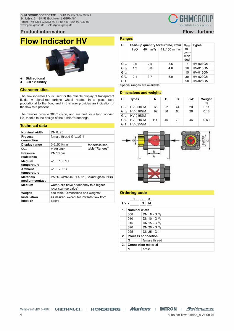
Flow Indicator HV
Bidirectional 360 ° visibility
Characteristics
The flow indicator HV is used for the reliable display of transparentfluids. A signal-red turbine wheel rotates in a glass tubeproportional to the flow, and in this way provides an indication ofthe flow rate present.
The devices provide 360 ° vision, and are built for a long workinglife, thanks to the design of the turbine's bearings.
Technical data
Nominal width DN 8..25
Process connection
female thread G 1/4..G 1
Display range 0.6..50 l/min for details see table "Ranges"Qmax. to 50 l/min
Pressure resistance
PN 10 bar
Medium temperature
-20..+100 °C
Ambient temperature
-20..+70 °C
Materialsmedium-contact
PA 66, CW614N, 1.4301, Sekurit glass, NBR
Medium water (oils have a tendency to a higher rotor start-up value)
GHM Messtechnik GmbH – Location HonsbergTenter Weg 2-8 42897 Remscheid Germany Fon +49-2191-9672-0 Fax -40www.ghm-messtechnik.de [email protected]
Product Information Sensors and Instrumentation
Flow Transmitter
Lineflow RRF
High accuracy / repeatability at low costs Determination of low flow rates Independent of location
Characteristics
With the RRF flow meter, an inline turbine is fitted in a plastichousing. A Hall sensor detects, contact-free, the rotation of theturbine, and outputs a frequency signal proportional to the flow.
Technical data
Sensor turbine fitted with magnets with Hall sensor
Nominal width DN 10
Process connection
male thread G 3/8 A
Metering range 0.5..30 l/min, for details see table "Ranges and pressure loss"
Measurement accuracy
±3 % of the measured value
Repeatability ±0.5 % of full scale value
Medium temperature
-20..+100 °C
Ambient temperature
0..80 °C
Pressure resistance
PN 14 bar
Pressure loss see table "Ranges and pressure loss"
Supply voltage 5..24 V DC at 8 mA
Frequency output NPN open collector at 50 mA max. (1 to 2.2 K Ohm pull-up resistor required)
GHM Messtechnik GmbH – Location HonsbergTenter Weg 2-8 42897 Remscheid Germany Fon +49-2191-9672-0 Fax -40www.ghm-messtechnik.de [email protected]
Product Information Sensors and Instrumentation
Handling and Operation
Installation
The turbine's direction of flow is marked by an arrow on the housing. Ideally, flow should be from bottom to top. In any case, prevent entrapment of air. Pressure surges when starting up can damage the turbine. The turbine should therefore first be flooded slowly, and only then should the nominal flow be applied. It should preferably be installed ahead of and not after valves in order to prevent the turbine from running empty.
The turbine is sealed into the pipework using Teflon tape or similar. It should be ensured that the thread is not damaged by tightening too strongly. Bending forces on the turbine caused by the pipework must be avoided under all circumstances.
Ordering code
1. 2. 3. 4. 5.
RRF- 010 A N
m=Option
1. Nominal width
010 DN 10 - G 3/8
2. Process connection
A male thread
3. Housing material
N nylon
4. Metering range
005 0.5.. 5 l/min
010 1.0..10 l/min
015 1.0..15 l/min
030 2.0..30 l/min
5. Electrical connection
K cable connection
F m open plug contact
Accessories
OMNI-TA converter / counter for control panel installation
GHM Messtechnik GmbH – Location HonsbergTenter Weg 2-8 42897 Remscheid Germany Fon +49-2191-9672-0 Fax -40www.ghm-messtechnik.de [email protected]
Product Information Sensors and Instrumentation
Flow Transmitter
RT-...AK
High precision No magnetic components in the flow space High pressure resistance
Characteristics
A turbine acts as the primary sensor; its rotational speed isproportional to the flow rate. The rotational speed is detected bymeans of a biased Hall sensors, i.e. there are no magnets in theflow space.
Technical data
Sensor biased Hall sensor
Nominal width DN 15..50
Process connection
male thread G 1/2 A...G 2 A
Metering ranges 1.8..1133 l/min for details, see table "Ranges"
Measurement accuracy
±1 % of full scale valuein the specified metering range, including linearity and repeatability
Medium temperature
-20..+85 °Coptionally -20..+150 °C (for 8 bar min.)
Ambient temperature
-20..+70 °C
Storage temperature
-20..+80 °C
Materials medium-contact
Housing stainless steel 315
Turbine stainless steel 430
Bearing tungsten carbide
Material electronics housing
CW614N nickelled
Max. particle size
0.5 mm
Pressure loss 0.3 bar at Qmax.
Pressure resistance
PN 250 bar
Supply voltage 10..30 V DC
Signal output transistor output "push-pull"(resistant to short circuits and polarity reversal)Iout = 100 mA max.
Current consumption
20 mA without load
Max. load current 100 mA
Electrical connection
for round plug connector M12x1, 4-pole
Ingress protection IP 67
Weight see table "Dimensions"
Conformity CE
Ranges
Types Metering range (1..5 mm²/s)
Pulses /litre
l/min m³/h ±10 %
RT-015AK001. 1.8.. 18 0.11.. 1.1 2900
RT-020AK002. 3.7.. 37 0.22.. 2.2 1700
RT-020AK004. 6.7.. 67 0.40.. 4.0 1100
RT-020AK008. 13.3.. 133 0.80.. 8.0 400
RT-025AK016. 26.7.. 267 1.60.. 16.0 190
RT-040AK034. 56.7.. 567 3.40.. 34.0 60
RT-050AK068. 113.3..1133 6.80.. 68.0 24
Wiring
Push-pull output, can be connected to PNP or NPN inputs.
GHM Messtechnik GmbH – Location HonsbergTenter Weg 2-8 42897 Remscheid Germany Fon +49-2191-9672-0 Fax -40www.ghm-messtechnik.de [email protected]
Product Information Sensors and Instrumentation
Dimensions
DN G ØD SW /AF
H L X Range m³/hat
1-5 mm² /s
Weightkg
15 1/2 38 35 71 64 19 0.11 – 1.1 0.30
20 3/4 38 35 72 64 19 0.22 – 2.2 0.40
20 3/4 38 35 72 64 19 0.40 – 4.0 0.40
20 3/4 40 38 75 83 22 0.80 – 8.0 0.40
25 1 47 44 78 88 23 1.60 – 16.0 0.60
40 11/2 60 52 84 114 28 3.40 – 34.0 1.40
50 2 70 64 89 132 29 6.80 – 68.0 1.90
Handling and Operation
Installation
As with all flow meters, if possible the turbine should be installedahead of a valve (on the pressure side). Good degassing should beensured. 10 x D calming sections are recommended before and af-ter the turbine in order to maintain the specified accuracies. Theturbine should be filled with fluid at all times. The electronics housing does not project into the flow space.
Ordering code
1. 2. 3. 4. 5. 6.
RT- A K T
m=Option
1. Nominal width
015 DN 15 - G 1/2 A
020 DN 20 - G 3/4 A
025 DN 25 - G 1 A
040 DN 40 - G 11/2 A
050 DN 50 - G 2 A
2. Mechanical connection
A male thread
3. Housing material
K stainless steel
4. Metering range
001 0.11.. 1.1 m³/h l
002 0.22.. 2.2 m³/h l
004 0.40.. 4.0 m³/h l
008 0.80.. 8.0 m³/h l
016 1.60..16.0 m³/h l
034 3.40..34.0 m³/h l
068 6.80..68.0 m³/h l
5. Signal output
T electronics
6. Option
H m high temperature model
Options
Flanged model, max. temperature 150 °C DN 80-300 PN 16 model for air / gas range from 0.05 m³/h
Accessories
Cable/round plug connector (KB...)see additional information “Accessories”
GHM Messtechnik GmbH – Location HonsbergTenter Weg 2-8 42897 Remscheid Germany Fon +49-2191-9672-0 Fax -40www.ghm-messtechnik.de [email protected]
Product Information Sensors and Instrumentation
Flow SwitchLABO-RT-S
Very short response time High precision No magnetic components in the flow space High pressure resistance
Characteristics
A turbine acts as the primary sensor; its rotational speed isproportional to the flow rate. The rotational speed is detected bymeans of pre-tensioned Hall sensors, i.e. there are no magnets inthe flow space.
The integrated converter / counter make available an electronicswitching output (push-pull) with adjustable characteristics(minimum/maximum) and hysteresis, which responds when anadjustable limit is fallen short of or exceeded.The switching value can be set to the currently existing flow using"teaching".
Models with analog or pulse output are also available.
Technical data
Sensor turbine with biased Hall sensor
Nominal width DN 15..50
Process connection
G 1/2 A...G 2 A (others on request)
Switching ranges see table "Ranges"
Measurement accuracy
±1 % of full scale valuein the specified metering rangeincluding linearity and repeatability
Pressure loss 0.3 bar at Qmax.
Pressure resistance
PN 250 bar
Medium temperature
-20..+85 °Coptionally -20..+150 °C (for 8 bar min.)
Ambient temperature
-20..+70 °C
Storage temp. -20..+80 °C
Materials medium-contact
Housing stainless steel 315
Turbine stainless steel 430
Bearing tungsten carbide
Materialelectronics housing
CW614N plated
Max. particle size 0.5 mm
Supplyvoltage
10..30 V DC
Power consumption
< 1 W (without load)
Switching output transistor output "push-pull"(resistant to short circuits and polarity reversal) lout = 100 mA max.
Display yellow LED (On = Normal / Off = Alarm / rapid flashing = Programming)
Electrical connection
for round plug connector M12x1, 4-pole
Ingress protection IP 67
Weight see table "Dimensions"
Conformity CE
Ranges
Types Switching range (1..5 mm²/s)
l/min m³/h
RT-015AK001. 1.8.. 18 0.11.. 1.1
RT-020AK002. 3.7.. 37 0.22.. 2.2
RT-020AK004. 6.7.. 67 0.40.. 4.0
RT-020AK008. 13.3.. 133 0.80.. 8.0
RT-025AK016. 26.7.. 267 1.60.. 16.0
RT-040AK034. 56.7.. 567 3.40.. 34.0
RT-050AK068. 113.3..1133 6.80.. 68.0
Wiring
Before the electrical installation, it must be ensured that the supplyvoltage corresponds to the data sheet.
It is recommended to use shielded wiring.
The push-pull output) can as desired be switched as a PNP or anNPN output.
GHM Messtechnik GmbH – Location HonsbergTenter Weg 2-8 42897 Remscheid Germany Fon +49-2191-9672-0 Fax -40www.ghm-messtechnik.de [email protected]
Product Information Sensors and Instrumentation
Dimensions
DN G ØD SW /AF
H L X Range m³/hat 1-5 mm² /s
Weightkg
15 1/2 38 35 69 64 19 0.11 – 1.1 0.32
20 3/4 38 35 70 64 19 0.22 – 2.2 0.42
20 3/4 38 35 70 64 19 0.40 – 4.0 0.42
20 3/4 40 38 73 83 22 0.80 – 8.0 0.42
25 1 47 44 76 88 23 1.60 – 16.0 0.63
40 11/2 60 52 82 114 28 3.40 – 34.0 1.42
50 2 70 64 87 132 29 6.80 – 68.0 1.92
Handling and operation
Installation
As with all flow meters, if possible the turbine should be installedahead of a valve (on the pressure side). Good degassing should beensured. 10 x D calming sections are recommended before and af-ter the turbine in order to maintain the specified accuracies. Theturbine should be filled with fluid at all times. The electronics housing does not project into the flow space.
Note
The switching value can be programmed by the user via "teaching".If desired, programmability can be blocked by the manufacturer.
The ECI-1 device configurator with associated software is availableas a convenient option for programming all parameters by PC, andfor adjustment.
Operation and programming
The switching value is set as follows: Apply the flow rate to be set to the device. Apply an impulse of at least 0.5 seconds and max. 2 seconds
duration to pin 2 (e.g. via a bridge to the supply voltage or a pulse from the PLC), in order to accept the measured value.
When the teaching is complete, pin 2 should be connected to 0 V, so as to prevent unintended programming.
The device has a yellow LED which flashes during theprogramming pulse. During operation, the LED serves as a statusdisplay for the switching output.
In order to avoid the need to transit to an undesired operatingstatus during the teach-in, the device can be provided ex-workswith a teach-offset. The teach-offset point is added to the currentlymeasured value before saving. The offset point can be positive ornegative.
Example: The switching value should be set to 80 l/min. However,it is possible only to reach 60 l/min without problems. In this case,the device would be set using a teach-offset of +20 l/min. At a flowrate of 60 l/min in the process, teaching would then store a value of80 l/min.
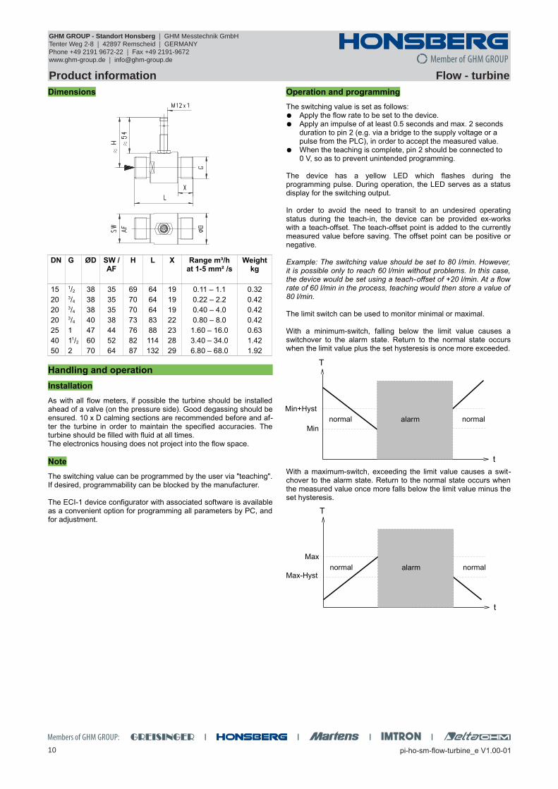
The limit switch can be used to monitor minimal or maximal.
With a minimum-switch, falling below the limit value causes aswitchover to the alarm state. Return to the normal state occurswhen the limit value plus the set hysteresis is once more exceeded.
With a maximum-switch, exceeding the limit value causes a swit-chover to the alarm state. Return to the normal state occurs whenthe measured value once more falls below the limit value minus theset hysteresis.
GHM Messtechnik GmbH – Location HonsbergTenter Weg 2-8 42897 Remscheid Germany Fon +49-2191-9672-0 Fax -40www.ghm-messtechnik.de [email protected]
Product Information Sensors and InstrumentationA changeover delay time (tDS) can be applied to switching to thealarm state. Equally, one switch-back delay time (tDR) of several canbe applied to switching back to the normal state.
In the normal state the integrated LED is on, in the alarm state it isoff, and this corresponds to its status when there is no supply volta-ge.
In the non-inverted (standard) model, while in the normal state theswitching output is at the level of the supply voltage; in the alarmstate it is at 0 V, so that a wire break would also display as an alarmstate at the signal receiver. Optionally, an inverted switching outputcan also be provided, i.e. in the normal state the output is at 0 V,and in the alarm state it is at the level of the supply voltage.
A Power-On-Delay function (ordered as a separate option) makes itpossible to maintain the switching output in the normal state for adefined period after application of the supply voltage.
Ordering code
The basic device is ordered e.g. RT-xxx with electronics e.g. LABO-RT-xxx
GHM Messtechnik GmbH – Location HonsbergTenter Weg 2-8 42897 Remscheid Germany Fon +49-2191-9672-0 Fax -40www.ghm-messtechnik.de [email protected]
Product Information Sensors and Instrumentation
Flow TransmitterLABO-RT-I / U / F / C
High precision No magnetic components in the flow space High pressure resistance 0..10 V, 4..20 mA , frequency/pulse output, completely
configurable
Characteristics
A turbine acts as the primary sensor; its rotational speed isproportional to the flow rate. The rotational speed is detected bymeans of pre-tensioned Hall sensors, i.e. there are no magnets inthe flow space.
The LABO-RT electronics make various output signals available:
Analog signal 0/4..20 mA (LABO-RT-I) Analog signal 0/2..10 V (LABO-RT-U) Frequency signal (LABO-RT-F) or Value signal pulse / x litres (LABO-RT-C)
A model with switching output is also available (see separatedatasheet).
If desired, the range end value can be set to the currently existingflow using "teaching".
Technical data
Sensor turbine with biased Hall sensor
Nominal width DN 15..50 (others on request)
Process connection
G 1/2 A...G 2 A
Metering ranges see table "Ranges"
Measurement accuracy
±1 % of full scale valuein the specified metering rangeincluding linearity and repeatability
Max. particle size 0.5 mm
Pressure loss 0.3 bar at Qmax.
Pressure resistance
PN 250 bar
Medium temperature
-20..+85 °Coptionally -20..+150 °C (for 8 bar min.)
Ambient temperature
-20..+70 °C
Storage temperature
-20..+80 °C
Materials medium-contact
Housing stainless steel 315
Turbine stainless steel 430
Bearing tungsten carbide
MaterialElectronics housing
CW614N nickelled
Supplyvoltage
10..30 V DC voltage output 10 V: 15..30 V DC
Power consumption
< 1 W (without load)
Output data: all outputs are resistant to short circuits and reversal polarity protected
Current output: 4..20 mA (0..20 mA available on request)
Voltageoutput:
0..10 V (2..10 V available on request)output current max. 20 mA
Frequencyoutput:
transistor output "push-pull"lout = 100 mA max.
Pulse output: transistor output "push-pull" lout = 100 mA max.pulse width 50 mspulse per volume is to be stated
Display yellow LCD shows operating voltage (LABO-RT-I / U) or output status (LABO-RT-F / C) (rapid flashing = Programming)
GHM Messtechnik GmbH – Location HonsbergTenter Weg 2-8 42897 Remscheid Germany Fon +49-2191-9672-0 Fax -40www.ghm-messtechnik.de [email protected]
Product Information Sensors and Instrumentation
Ranges
Types Metering range (1..5 mm²/s)
l/min m³/h
RT-015AK001. 1.8.. 18 0.11.. 1.1
RT-020AK002. 3.7.. 37 0.22.. 2.2
RT-020AK004. 6.7.. 67 0.40.. 4.0
RT-020AK008. 13.3.. 133 0.80.. 8.0
RT-025AK016. 26.7.. 267 1.60..16.0
RT-040AK034. 56.7.. 567 3.40..34.0
RT-050AK068. 113.3..1133 6.80..68.0
Wiring
Before the electrical installation, it must be ensured that the supplyvoltage corresponds to the data sheet.It is recommended to use shielded wiring.The push-pull output of the frequency or pulse output version canas desired be switched as a PNP or an NPN output.
Dimensions
DN G ØD SW /AF
H L X Range m³/hat 1-5 mm² /s
Weightkg
15 1/2 38 35 69 64 19 0.11 – 1.1 0.32
20 3/4 38 35 70 64 19 0.22 – 2.2 0.42
20 3/4 38 35 70 64 19 0.40 – 4.0 0.42
20 3/4 40 38 73 83 22 0.80 – 8.0 0.42
25 1 47 44 76 88 23 1.60 – 16.0 0.63
40 11/2 60 52 82 114 28 3.40 – 34.0 1.42
50 2 70 64 87 132 29 6.80 – 68.0 1.92
Handling and operation
Installation
As with all flow meters, if possible the turbine should be installedahead of a valve (on the pressure side). Good degassing should beensured. 10 x D calming sections are recommended before and af-ter the turbine in order to maintain the specified accuracies. Theturbine should be filled with fluid at all times. The electronics housing does not project into the flow space.
Note
The fullscale end value can be programmed by the user via "tea-ching". Requirement for programmability must be stated when or-dering, otherwise the device cannot be programmed.
The ECI-1 device configurator with associated software is availableas a convenient option for programming all parameters by PC, andfor adjustment.The teaching option is not available for the pulse output version.
Operation and programming
The teaching process can be carried out by the user as follows: The flow rate to be set is applied to the device. Apply an impulse of at least 0.5 seconds and max. 2 seconds
duration to pin 2 (e.g. via a bridge to the supply voltage or a pulse from the PLC), in order to accept the measured value.
When the teaching is complete, pin 2 should be connected to 0 V, so as to prevent unintended programming.
The devices have a yellow LED which flashes during theprogramming pulse. During operation, the LED serves as anindicator of operating voltage (for analog output) or of switchingstatus (for frequency or pulse output).
To avoid the need to transit to an undesired operating status for thepurpose of teaching, the device can be provided ex-works with ateach-offset. The teach-offset point is added to the currentlymeasured value before saving. The offset point can be positive ornegative.
Example: The end of the metering range should be set to 80 %.However, only 60 % can be achieved without problem. In this case,the device would be ordered with a "teach-offset" of +20°%.. At aflow rate of 60 % in the process, teaching would then store a valueof 80 %.
If necessary, a far greater number of parameters can also be programmed using the ECI-1 device configurator.
GHM Messtechnik GmbH – Location HonsbergTenter Weg 2-8 42897 Remscheid Germany Fon +49-2191-9672-0 Fax -40www.ghm-messtechnik.de [email protected]
Product Information Sensors and Instrumentation
Flow Transmitter / Switch FLEX-RT
Versatile turbine flow sensor Switching output and analog output (4..20 mA / 0..10 V) Top quality materials Designed for industrial use Ingress protection IP 67 Infinitely adjustably rotatable cable outlet for clean
alignment Small, compact construction Very simple installation
Characteristics
A turbine acts as the primary sensor; its rotational speed isproportional to the flow rate. The rotational speed is detected bymeans of a biased Hall sensors, i.e. there are no magnets in theflow space.
The FLEX transducer located on the sensor has an analog output(4..20 mA or 0..10 V) and a switching output, which can beconfigured as a limit switch for monitoring minimal or maximal, oras a frequency output.
The switching output is designed as a push-pull driver, and cantherefore be used both as a PNP or an NPN output. The state ofthe switching output is signalled with a yellow LED in the switchingoutlet; the LED has all-round visibility.The sensor is configured in the factory, or alternatively this can bedone with the aid of the optionally available ECI-1 deviceconfigurator (USB interface for PC). A selectable parameter can bemodified on the device, with the aid of the magnet clip provided. Inthis case, the current measured value is saved as the parametervalue. Examples of these parameters are the switching value or themetering range end value.The stainless steel electronics housing is rotatable, so it is possibleto orient the cable outlet after installation.
Technical data
Sensor turbine with biased Hall sensor
Nominal width DN 15..50 (others on request)
Process connection
G 1/2 A...G 2 A
Metering ranges see table "Ranges"
Measurement accuracy
±1 % of full scale valuein the specified metering rangeincluding linearity and repeatability
Medium temperature
-20..+85 °Coptionally -20..+150 °C (for 8 bar min.)
Ambient temperature
-20..+70 °C
Storage temperature
-20..+80 °C
Materialsmedium-contact
Housing stainless steel 316
Turbine stainless steel 430
Bearing tungsten carbide
Materialelectronics housing
stainless steel 1.4305adapter CW614N plated
Max. particle size 0.5 mm
Pressure loss (average)
0.3 bar at Qmax.
Pressure PN 250 bar
Supply voltage 18..30 V DC
Power consumption
<1 W
Analog output 4..20 mA / load 500 Ohm max. or 0..10 V / load min. 1 kOhm
Switching output transistor output "push-pull"(resistant to short circuits and polarity reversal)Iout = 100 mA max.
Switching hysteresis
adjustable (please state when ordering)Standard setting:2 % F.S., for Min-switch, position of the hysteresis above the limit value, and for Max-switch, below the limit value
GHM Messtechnik GmbH – Location HonsbergTenter Weg 2-8 42897 Remscheid Germany Fon +49-2191-9672-0 Fax -40www.ghm-messtechnik.de [email protected]
Product Information Sensors and Instrumentation
Signal output curves
Value x = Begin of the specified range
Current output Voltage output
Frequency output
fmax selectable in the range of upto 2000 Hz
Other characters on request.
Ranges
Types Metering range (1..5 mm²/s)
l/min m³/h
RT-015AK001. 1.8.. 18 0.11.. 1.1
RT-020AK002. 3.7.. 37 0.22.. 2.2
RT-020AK004. 6.7.. 67 0.40.. 4.0
RT-020AK008. 13.3.. 133 0.80.. 8.0
RT-025AK016. 26.7.. 267 1.60..16.0
RT-040AK034. 56.7.. 567 3.40..34.0
RT-050AK068. 113.3..1133 6.80..68.0
Wiring
Before the electrical installation, it must be ensured that the supplyvoltage corresponds with the data sheet.
It is recommended to use shielded wiring,
Dimensions
DN G ØD SW /AF
H L X Range m³/hat 1-5 mm² /s
Weight kg
15 1/2 38 35 81.5 64 19 0.11 – 1.1 0.44
20 3/4 38 35 82.5 64 19 0.22 – 2.2 0.54
20 3/4 38 35 82.5 64 19 0.40 – 4.0 0.54
20 3/4 40 38 85.5 83 22 0.80 – 8.0 0.54
25 1 47 44 88.5 88 23 1.60 – 16.0 0.74
40 11/2 60 52 94.5 114 28 3.40 – 34.0 1.54
50 2 70 64 99.5 132 29 6.80 – 68.0 2.04
Handling and operation
Installation
As with all flow meters, if possible the turbine should be installedahead of a valve (on the pressure side). Good degassing should beensured. 10 x D calming sections are recommended before and af-ter the turbine in order to maintain the specified accuracies. Theturbine should be filled with fluid at all times. The electronics housing does not project into the flow space.
Programming
The electronics contain a magnetic contact, with the aid of whichdifferent parameters can be programmed. Programming takesplace when a magnet clip is applied for a period between 0.5 and2 seconds to the marking located on the label. If the contact time islonger or shorter than this, no programming takes place (protectionagainst external magnetic fields).
After the programming ("teaching"), the clip can either be left on thedevice, or removed to protect data. The device has a yellow LED which flashes during theprogramming pulse. During operation, the LED serves as a statusdisplay for the switching output.In order to avoid the need to transit to an undesired operatingstatus during "teaching", the device can be provided ex-works witha "teach-offset". The "teach-offset" value is added to the currentlymeasured value before saving (or is subtracted if a negative valueis entered).
GHM Messtechnik GmbH – Location HonsbergTenter Weg 2-8 42897 Remscheid Germany Fon +49-2191-9672-0 Fax -40www.ghm-messtechnik.de [email protected]
Product Information Sensors and InstrumentationExample: The switching value is to be set to 70 % of the metering range, because at this flow rate a critical process status is to be notified. However, only 50% can be achieved without danger. In this case, the device would be ordered with a "teach-offset" of +20 %. At 50 % in the process, a switching value of 70 % would then be stored during "teaching".
Normally, programming is used to set the limit switch. However, ifdesired, other parameters such as the end value of the analog orfrequency output may also be set.
The limit switch can be used to monitor minimal or maximal.
With a minimum-switch, falling below the limit value causes a swit-chover to the alarm state. Return to the normal state occurs whenthe limit value plus the set hysteresis is again exceeded.
With a maximum-switch, exceeding the limit value causes a swit-chover to the alarm state. Return to the normal state occurs whenthe measured value once more falls below the limit value minus theset hysteresis.
A switchover delay time (tDS) can be applied to the switchover to thealarm state. Equally, one switch-back delay time (tDR) of several canbe applied to switching back to the normal state.
In the normal state the integrated LED is on, in the alarm state it isoff, and this corresponds to its status when there is no supply volta-ge.
In the non-inverted (standard) model, while in the normal state theswitching output is at the level of the supply voltage; in the alarmstate it is at 0 V, so that a wire break would also display as an alarmstate at the signal receiver. Optionally, an inverted switching outputcan also be provided, i.e. in the normal state the output is at 0 V,and in the alarm state it is at the level of the supply voltage.
A Power-On delay function (ordered as a separate option) makes itpossible to maintain the switching output in the normal state for adefined period after application of the supply voltage.
GHM Messtechnik GmbH – Location HonsbergTenter Weg 2-8 42897 Remscheid Germany Fon +49-2191-9672-0 Fax -40www.ghm-messtechnik.de [email protected]
Product Information Sensors and Instrumentation
Flow Transmitter / Switch OMNI-RT
Universal turbine flow sensor Analog output, two switching outputs Clear, easily legible, illuminated LCD display Modifiable units in the display Designed for industrial use Small, compact construction Simple installation
Characteristics
A turbine acts as the primary sensor; its rotational speed isproportional to the flow rate. The rotational speed is detected bymeans of pre-tensioned Hall sensors, i.e. there are no magnets inthe flow space.
The OMNI transducer located on the sensor has a backlit graphicsLCD display which is very easy to read, both in the dark and inbright sunlight. The graphics display allows the presentation ofmeasured values and parameters in a clearly understandable form.The measured values are displayed to 4 places, together with theirphysical unit, which may also be modified by the user. Theelectronics have an analog output (4..20 mA or 0..10 V) and twoswitching outputs, which can be used as limit switches formonitoring minimal or maximal, or as two-point controllers.
The switching outputs are designed as push-pull drivers, and cantherefore be used both as PNP and NPN outputs. Exceeding limitvalues is signalled by a red LED which is visible over a longdistance, and by a cleartext in the display. The stainless steel casehas a hardened non-scratch mineral glass pane. It is operated by aprogramming ring fitted with a magnet, so there is no need to openthe operating controls housing, and its leakproofness ispermanently ensured.
By turning the ring to right or left, it is simple to modify theparameters (e.g. switching point, hysteresis...). To protect fromunintended programming, it can be removed, turned through 180 °and replaced, or completely removed, thus acting as a key.
OPTION C:Preset Counter with external reset option, complementary switchingoutputs and actual value display.
OPTION C1:Instantaneous value display with analogue output, pulse-volume output and totalizer
Technical data
Sensor turbine with pre-tensioned Hall sensor
Nominal width DN 15..50
Process connection
G 1/2 A...G 2 A
Metering ranges see table "Ranges"
Measurement accuracy
±1 % of full scale valuein the specified metering rangeincluding linearity and repeatability
Medium temperature
-20..+85 °Coptionally -20..+150 °C (for 8 bar min.)
Ambienttemperature
-20..+70 °C
Storage temperature
-20..+80 °C
Max. particle size 0.5 mm
Pressure loss maximum 0.3 bar at Qmax.
Pressure PN 250 bar
Materialsmedium-contact
Housing stainless steel 316
Turbine stainless steel 430
Bearing tungsten carbide
MaterialsElectronic housing
Housing stainless steel 1.4305
Glass mineral glass hardened
Magnet samarium-Cobalt
Ring POM
Supply voltage 18..30 V DC
Power consumption
< 1 W
Analog output 4..20 mA / max. load 500 Ω or0..10 V / min. load 1 kΩ
Switching outputs transistor output "push-pull"(resistant to short circuits and polarity reversal)Iout = 100 mA max.
Hysteresis adjustable, position of the hysteresis depends on minimum or maximum
Display backlit graphical LCD-Display (transreflective), extended temperature range -20..+70 °C, 32 x 16 pixels, background illumination, displays value andunit, flashing LED signal lamp with simultaneous message on the display.
Electrical connection
for round plug connector M12x1, 5-pole
Ingress protection IP 67 / (IP 68 when oil-filled)
GHM Messtechnik GmbH – Location HonsbergTenter Weg 2-8 42897 Remscheid Germany Fon +49-2191-9672-0 Fax -40www.ghm-messtechnik.de [email protected]
Product Information Sensors and Instrumentation
Signal output curves
Value x = Begin of the specified range = not specified range
Current output Voltage output
Other characters on request.
Ranges
Types Metering range (1..5 mm²/s)
l/min m³/h
OMNI-RT-015AK001. 1.8.. 18 0.11.. 1.1
OMNI-RT-020AK002. 3.7.. 37 0.22.. 2.2
OMNI-RT-020AK004. 6.7.. 67 0.40.. 4.0
OMNI-RT-020AK008. 13.3.. 133 0.80.. 8.0
OMNI-RT-025AK016. 26.7.. 267 1.60..16.0
OMNI-RT-040AK034. 56.7.. 567 3.40..34.0
OMNI-RT-050AK068. 113.3..1133 6.80..68.0
Wiring
connector M12x1
See separate wiring at C and C1 option in the separate descriptions.
Before the electrical installation, it must be ensured that the supplyvoltage corresponds to the data sheet.The use of shielded cabling is recommended.
Dimensions
G DN ØD SW /AF
H L X Range m³/hat 1-5 mm² /s
Weight
G 1/2 15 38 35 74 64 19 0.11 – 1.1 0.50
G 3/4 20 38 35 75 64 19 0.22 – 2.2 0.60
G 3/4 20 38 35 75 64 19 0.40 – 4.0 0.60
G 3/4 20 40 38 78 83 22 0.80 – 8.0 0.60
G 1 25 47 44 81 88 23 1.60 – 16.0 0.80
G 11/2 40 60 52 87 114 28 3.40 – 34.0 1.60
G 2 50 70 64 92 132 29 6.80 – 68.0 2.10
Gooseneck optionA gooseneck (optional) between the electronics head and the primary sensor provides freedom in the orientation of the sensor. This option simultaneously provides thermal decoupling between the two units.
Handling and operation
Installation
As with all flow meters, if possible the turbine should be installedahead of a valve (on the pressure side). Good degassing should beensured. 10 X D calming sections are recommended before and af-ter the turbine in order to maintain the specified accuracies. Theturbine should be filled with fluid at all times.
It should be ensured that the flow meter and the OMNI electronicsare matched to each other.
The electronics housing is permanently connected to the primarysensor, and cannot be removed by the user. After installation, theelectronic head can be turned to the best position for reading.
GHM Messtechnik GmbH – Location HonsbergTenter Weg 2-8 42897 Remscheid Germany Fon +49-2191-9672-0 Fax -40www.ghm-messtechnik.de [email protected]
Product Information Sensors and Instrumentation
Programming
The annular gap of the programming ring can be turned to positions1 and 2. The following actions are possible:
Set to 1 = continue (STEP)Set to 2 = modify (PROG)
Neutral position between1 and 2
The ring can be removed to act as a key, or turned through 180 °and replaced to create a programming protector. Operation is by dialog with the display messages, which makes itsuse very simple.Starting from the normal display (present value and unit), if 1 (STEP) is repeatedly selected, then the display shows the followinginformation in this order:
Display of the parameters, using position 1
Switching value S1 (switching point 1 in the selected unit) Switching characteristic of S1
MIN = Monitoring of minimum valueMAX = Monitoring of maximum value
Hysteresis 1 (hysteresis value of S1 in the set unit) Switching value S2 Switching characteristic of S2 Hysteresis 2 Code
After entering the code 111, further parameters can be defined: Filter (settling time of the display and output) Physical unit (Units) Output: 0..20 mA or 4..20 mA 0/4 mA (measured value corresponding to 0/4 mA) 20 mA (measured value corresponding to 20 mA)
For models with a voltage output, replace 20 mA accordingly with 10 V.
Edit, using position 2
If the currently visible parameter is to be modified: Turn the annular gap to position 2, so that a flashing cursor
appears which displays the position which can be modified. By repeatedly turning to position 2, values are increased; by
turning to position 1, the cursor moves to the next digit Leave the parameter by turning to position 1 (until the cursor
leaves the row); this accepts the modification. If there is no action within 30 seconds, the device returns to the
normal display range without accepting the modification.
The limit switches S1 and S2 can be used to monitor minimal ormaximal.With a minimum-switch, falling below the limit value causes aswitchover to the alarm state. Return to the normal state occurswhen the limit value plus the set hysteresis is once more exceeded.
With a maximum-switch, exceeding the limit value causes a swit-chover to the alarm state. Return to the normal state occurs whenthe measured value once more falls below the limit value minus theset hysteresis.
The change to the alarm state is indicated by the integrated redLED and a cleartext in the display.While in the normal state the switching outputs are at the level ofthe supply voltage; in the alarm state they are at 0 V, so that a wirebreak would also display as an alarm state at the signal receiver.
Overload displayOverload of a switching output is detected and indicated on thedisplay ("Check S 1 / S 2"), and the switching output is switched off.
Simulation modeTo simplify commissioning, the sensor provides a simulation mode for the analog output. It is possible to create a programmable value in the range 0..26.0 mA at the output (without modifying the pro-cess variable). This allows the wiring run between the sensor and the downstream electronics to be tested during commissioning. This mode is accessed by means of Code 311.
Factory settingsAfter modifying the configuration parameters, it is possible to resetthem to the factory settings at any time using Code 989.
GHM Messtechnik GmbH – Location HonsbergTenter Weg 2-8 42897 Remscheid Germany Fon +49-2191-9672-0 Fax -40www.ghm-messtechnik.de [email protected]
Product Information Sensors and Instrumentation
Ordering code
The basic device is ordered e.g. RT-xxx with electronics e.g. OMNI-RT-xxxx
1. 2. 3. 4. 5. 6.
RT- A K E
7. 8. 9. 10. 11.
OMNI-RT- S
m=Option
1. Nominal width
015 DN 15 - G 1/2 A
020 DN 20 - G 3/4 A
025 DN 25 - G 1 A
040 DN 40 - G 11/2 A
050 DN 50 - G 2 A
2. Mechanical connection
A male thread
3. Housing material
K stainless steel
4. Metering range
001 0.11.. 1.1 m³/h l
002 0.22.. 2.2 m³/h l
004 0.40.. 4.0 m³/h l
008 0.80.. 8.0 m³/h l
016 1.60..16.0 m³/h l
034 3.40..34.0 m³/h l
068 6.80..68.0 m³/h l
5. Connection for
E electronics
6. Option
H high temperature model
7. For nominal width
015 DN 15 - G 1/2 A l
020 DN 20 - G 3/4 A l
025 DN 25 - G 1 A l
040 DN 40 - G 11/2 A l
050 DN 50 - G 2 A l
8. Analog output
I current output 0/4..20 mA l
U m voltage output 0/2..10 V l
K without l
9. Electrical connection
S for round plug connector M12x1, 5-pole
10. High temperature
H m 150 °C version
O m
tropical modeloil-filled version for heavy duty or external use
11. Option 2
C m Counter C
C1 m Counter C1
Options
Counter C (hardware and software option):Preset Counter with external reset option, complementary switchingoutputs and actual value display(modified wiring diagram!)
Counter C1 (software option):Instantaneous value display with analogue output, pulse-volume output and totalizer
Accessories
Cable/round plug connector (KB...)see additional information “Accessories”
GHM Messtechnik GmbH – Location HonsbergTenter Weg 2-8 42897 Remscheid Germany Fon +49-2191-9672-0 Fax -40www.ghm-messtechnik.de [email protected]
Product Information Sensors and Instrumentation
OMNI-C Counter
Counter for flow transmitters:•
Piston• Dynamic diaphragm• Rotor
• Turbine• Gear• Screw• Calorimetry• MID• Vortex
Simple totalisation Simple filling counter with programmable end signal Control switchover at present value Automatic, dynamic change of display unit and decimal
places in the graphics display Antivalent outputs Simple guided menu via graphics display
Characteristics
The totaliser of the OMNI flow rate system enables a totalisation ormeasurement of consumption for all HONSBERG device families(for fluids and gases) with which the OMNI system is compatible;this is independent of the input signal, pulse or analogue input, andof the measurement process.
Simple filling control is also possible. Here, the counter can be setto count upwards or downwards.When the preset point is reached, a switching signal is emittedwhich is available in antivalent form to two outputs.Resetting can be carried out by means of a signal input or also by aprogramming ring.
The state of the counter is indicated in an LCD display with onlyfour digits. Here, the number of decimal places and the unitdisplayed is continuously matched to the current state of thecounter. In this case, the smallest value which can be displayed is0.001 ml (= 1 µl), and the largest is 9999 m³. The counter thereforehas 13 places, of which the four most significant are displayed atany one time. The display resolution at all times is therefore at least1 per thousand of the displayed value, or better, and this generallyexceeds the accuracy of the connected flow transmitter. The non-displayed digits of the counter are in that case irrelevant to theaccuracy of the measurement.The automatic dynamic changeover of units in the display inrelation to the state of the counter makes the value easy to read inspite of a display with only four digits. In addition, user configurationof the counter is unnecessary.
In addition to the totalised value, the present flow rate can bedisplayed.
Technical data
Counter range 0.000 ml to 9999 m³with automatic setting of the decimal places and of the applicable unit.
Switching signaloutputs(Pin 4 + 5)
2 x pushpull output, max. 100 mA, resistant to short circuits and polarity reversal, antivalent states, configurable on the device as a wipe or edge signal
Counter reset signal (Pin 2)
Input 18..30 V resistant to short circuits and reversed polarityPIN 2, wiper signal, positive or negative edge can be selected locally
Wiring
Before the connecting the supply voltage, it must be ensured that this corresponds with the data sheet! The use of shielded cabling isrecommended
GHM Messtechnik GmbH – Location HonsbergTenter Weg 2-8 42897 Remscheid Germany Fon +49-2191-9672-0 Fax -40www.ghm-messtechnik.de [email protected]
Product Information Sensors and Instrumentation
Handling and operation
Installation
For assembly, please observe the handling instructions for thedifferent device versions.
After assembly, it is possible to move the sensor head to the mostoptimal reading position opposite the sensor part using its rotatingfunction.
Programming
On the display, the counter indicates the state of the totaliser as a value and unit. The units ml, L, m³ are set automatically.
For operation as a totaliser, no configuration by the user is necessary.
To use the other functions, configuration may be required. This iscarried out using the programming ring located on the device.
The annular gap of the programming ring can be turned to positions1 and 2. The following actions are possible:
Set to 1 = continue (STEP)Set to 2 = modify (PROG)
Neutral position between1 and 2
The ring can be removed to act as a key, or turned through 180 °and replaced to create a programming protector.
Operation is by dialogue with the display messages, which makesits use very simple.
The control display of the present flow rate depends on themetering range of the selected flow transmitter, and has alreadybeen set appropriately in the factory (ml/min, l/min, l/h, m³/h).It is activated by turning the ring to position 1After 10 seconds, the display automatically returns to the totalisermode.
For operation as a preset counter, the following must be set:
1. The preset point2. The type of output signal ("Preset has been reached"):
Signal edge / wiper pulse width of the wiper pulse, if required
3. The unit of the preset point: (ml, litre, m³).
Starting from the normal display (total and unit), if 1 (Step) isselected repeatedly, then the counter shows the followinginformation:
Normal display is total and unit (e.g. litre) Display of present value (e.g. l/min) Preset point incl. type of switching output. Code
The code gives access to various input levels into whichparameters can be entered (so that this does not occurinadvertently, the code must be entered!).
Code 111:
Gate time (available only for sensors which transmit frequency) Filter time Direction of count (pos / neg) Unit for switching value reset point Decimal place for switching value / reset point Switching type for switching value (edge / wiper signal) Pulse duration (for wiper signal) Reset method (manual / via signal)
Code 100:
Manual reset for totaliser
The detailed flow chart for operation is available in the "Operatinginstructions for OMNI-C".
Momentary value indicator and totalisation Pulse output with adjustable pulse per volume Antivalent outputs Analogue output of the momentary value Simple guided menu via graphics display
Characteristics
The local OMNI-C1 electronics offers a momentary value indicatorand a totalisation of the flow rate quantity.
The momentary value is output at the analogue output as a 4..20mA signal (or optionally as a 0..10 V signal).In addition, the electronics has a pulse output, which outputs apulse after a preset quantity with a duration of 36 ms. The pulse isavailable at two switching outputs in anitvalent form.
The primary displayed value is the flow rate. Using theprogramming ring, you can temporarily switch to the totalisation.
The state of the totalisation is indicated in an LCD display with onlyfour digits. Here, the number of decimal places and the unitdisplayed is continuously matched to the current state of thecounter. In this case, the smallest value which can be displayed is0.001 ml (= 1 µl), and the largest is 9999 m³. The counter thereforehas 13 places, of which the four most significant are displayed atany one time. The display resolution at all times is therefore at least1 per thousand of the displayed value, or better, and this generallyexceeds the accuracy of the connected flow transmitter. The non-displayed digits of the counter are in that case irrelevant to theaccuracy of the measurement.The automatic dynamic changeover of units in the display inrelation to the state of the counter makes the value easy to read inspite of a display with only four digits. In addition, user configurationof the counter is unnecessary.
Counter C:Instead of the counter option C1 the counter option C is available(see corresponding datasheet). It offers a totalizer with adjustablepreset value and external reset. This allows to realize a fillingcontrol application for example. Additionally the actual flow ratevalue can be displayed, however without an analog output.
Technical data
Counter range 0.000 ml to 9999 m³with automatic setting of the decimal places and of the applicable unit
Pulse outputs(Pin 4 + 5)
2 x pushpull output, max. 100 mA, resistant to short circuits and polarity reversal,antivalent statuses, pulse width 36 ms
Wiring
Plug connector M12x1
Before the electrical installation, it must be ensured that the supplyvoltage corresponds to the data sheet.The use of shielded cabling is recommended.
GHM Messtechnik GmbH – Location HonsbergTenter Weg 2-8 42897 Remscheid Germany Fon +49-2191-9672-0 Fax -40www.ghm-messtechnik.de [email protected]
Product Information Sensors and Instrumentation
Handling and operation
Installation
For assembly, please observe the handling instructions for thedifferent device versions.
After assembly, it is possible to move the sensor head to the mostoptimal reading position opposite the sensor part using its rotatingfunction.
Programming
The resetting of the meter to zero takes place through theprogramming.
The stainless steel case has a hardened non-scratch mineral glasspane. It is operated by a programming ring fitted with a magnet, sothere is no need to open the operating controls housing, and itsleakproofness is permanently ensured.
By turning the ring to right or left, it is simple to modify theparameters (e.g. switching point, hysteresis...). To protect fromunintended programming, it can be removed, turned through 180 °and replaced, or completely removed, thus acting as a key.
On the display, the meter indicates the current flow rate as a value and unit. For this purpose, no adjustments by the user are necessary.
To use the other functions, configuration may be required. This iscarried out using the programming ring located on the device.
The annular gap of the programming ring can be turned to positions1 and 2. The following actions are possible:
Set to 1 = continue (STEP)Set to 2 = modify (PROG)
Neutral position between 1 and 2
The ring can be removed to act as a key, or turned through 180 °and replaced to create a programming protector.Operation is by dialogue with the display messages, which makesits use very simple.
Rotating the ring once to Pos. 1 displays the totaliser status. In theprocess, the unit is automatically set to the quantity alreadycounted.After 10 seconds, the display automatically returns to themomentary value mode.If the ring is turned to position 1 again while the totaliser status isshown, the code input is reached.The code gives access to various input levels into whichparameters can be changed (so that this does not occurinadvertently, the code must be entered!).
Code 100:
Reset for totaliser
Code 111:
Filter Enables the input of a filter time in multiple levels
The filter time describes the time after whicha volatile change in flow occurs until the display value has adopted the new value
PlsUnit Enables the input of the unit of the pulse volume (pulse per volume), e.g. cm³, Litre, m³
PlsVal Enables the input of the meter value of the pulse flow (0..9999)
Output Enables switching of the analogue output between 0..20 mA and 4..20 mA (optionally (0..10 V and 2..10 V)
4 mA Defines the momentary value at which 4 mAshould be output
20 mA Defines the momentary value at which 20 mA should be output
GHM Messtechnik GmbH – Location HonsbergTenter Weg 2-8 42897 Remscheid Germany Fon +49-2191-9672-0 Fax -40www.ghm-messtechnik.de [email protected]
Product Information Sensors and Instrumentation
Device Configurator
ECI-1
Can be used on site for:– parameter modification– firmware update– adjustment of inputs and outputs
Can be connected via USB
Characteristics
The device configurator ECI-1 is an interface which allows theconnection of microcontroller-managed HONSBERG sensors to theUSB port of a computer. Together with the Windows software "HONSBERG DeviceConfigurator" it enables
the modification of all the sensor's configuration settings the reading of measured values the adjustment of inputs and outputs firmware updates
Technical data
Supply voltage 12..30 V DC (depending on the connected sensor) and via USB
Power consumption
< 1 W
Connection
Sensor cable bushing M12x1, 5-pole, straight lengthapprox. 50 cm
Lead device connector M12x1, 5-pole
USB USB bushing type B
Operating temperature
0..50 °C
Storage temperature
-20..+80 °C
Dimensions of housing
98 mm (L) x 64 mm (W) x 38 mm (H)
Housing material ABS
Ingress protection IP 40
Handling and operation
Connection
The device configurator is intended for temporary connection to theapplication. It is connected between the the existing sensor leadand the sensor. Power supply is via the supply to the sensor andthe computer's USB port. When inactive (no communication), theconfigurator behaves completely neutrally; all signals from the sen-sor remain available to the application. During communication bet-ween computer and sensor, the signal wirings are separated in theconfigurator, so that in this state the sensor's output signals are notavailable.
To connect 4-pole leads without a middle hole to the installed 5-pole device connector, adapter K04-05 is included. 4-pole leadswith a middle hole can be used without an adapter.
Ordering code
Device configurator (for scope of delivery, see the diagram below)
ECI-1
Scope of delivery
1. Device configurator ECI-12. USB cable3. Adapter K04-054. Plug KB05G 5. Cable K05PU-02SG6. Carrying case
Incl. software
Accessories:
Mains connector 24 V DC(with fitted round plugconnector, 5-pole, incl. international plug set)
GHM Messtechnik GmbH – Sales Center InternationalSchloßstraße 6 88453 Erolzheim Germany Fon +49-7354-937233-0 Fax -88www.ghm-messtechnik.de [email protected]
Product Information Sensors and Instrumentation
OptionsLABO transmitter - Temperature up to 150 °C
All LABO transmitters can be used with electronics positioned in a separate area with media temperatures up to 150 °C.
OMNI - Tropical model
This OMNI electronic option should be used where temperatures change quickly, or for external installations (the device is filled with oil, and thus prevents condensate formation in the electronics hou-sing, even under adverse circumstances)
GHM Messtechnik GmbH – Sales Center InternationalSchloßstraße 6 88453 Erolzheim Germany Fon +49-7354-937233-0 Fax -88www.ghm-messtechnik.de [email protected]
Product Information Sensors and Instrumentation
AccessoriesFilter
Type ZV Type ZE The HONSBERG filters are offered for the protection of the devicesfrom dirt or as independent components for coarse and finefiltration of liquids.
For more information, see additional product information.
Round plug connector 4 / 5-pin
Ordering code
Self-assembly1. 2.
KB
1. Number of pins
04 4-polig
05 5-polig
2. Steckerabgang
G gerade
W gewinkelt 90 °
Panel meter OMNI-TA
Converter with the same data as the OMNI in situ electronics; but as an external panel-mounting variant with IP 67 housing.
OMNI - Remote
Function is identical to OMNI-in situ. Connection to the sensor is, however, made by wire, and so the measurement point and displaylocation can be apart