Product Manual 2800 Compact Operator Interface Terminal for use with Allen-Bradley ULTRA 3000 Drives Quartech Corporation 15923 Angelo Drive Macomb Township, Michigan 48042-4050 Phone: (586) 781-0373 FAX: (586) 781-0378 www.quartechcorp.com PM2800U3K Revision 4 The product described in this document can have a variety of uses, the user and those responsible for applying this equipment must satisfy themselves as to the acceptability of each application and the use of the unit. Under no circumstances will QUARTECH CORPORATION be responsible or liable for any damage, including indirect or consequential losses resulting from the use, misuse, or application of the unit. The text, illustrations, charts, and examples included in this document are intended solely to help explain applications of the product. Due to the many variables associated with specific uses or applications, QUARTECH CORPORATION cannot assume responsibility or liability for actual use based upon the data provided in this document. No patent liability is assumed by QUARTECH CORPORATION with respect to the use of circuits, information, equipment, or software described in this document. This document is subject to change without notice.
The product described in this document can have a variety of uses, the user and those responsible for applying thisequipment must satisfy themselves as to the acceptability of each application and the use of the unit. Under nocircumstances will QUARTECH CORPORATION be responsible or liable for any damage, including indirect orconsequential losses resulting from the use, misuse, or application of the unit.
The text, illustrations, charts, and examples included in this document are intended solely to help explain applicationsof the product. Due to the many variables associated with specific uses or applications, QUARTECH CORPORATIONcannot assume responsibility or liability for actual use based upon the data provided in this document.
No patent liability is assumed by QUARTECH CORPORATION with respect to the use of circuits, information,equipment, or software described in this document.
This document is subject to change without notice.
Allen-Bradley SLC500, DH-485. Allen-Bradley SLC500, DF1. (MicroLogix PLC)Allen-Bradley PLC-5, DF1. Allen-Bradley PLC-2Fuji Electric N Series GE Fanuc Series 90Mitsubishi FX Series Modicon Modbus.Omron Host Link Idec, Micro3 & Micro3CToshiba EX100 Protocol Toshiba T1-Series Computer LinkYaskawa MP930 Memobus Generic ASCII, with definable string format.Slave ASCII Terminal Allen-Bradley Ultra 100/200 Drive
PM2800U3K Revision 4
Section 1: Introduction Page 1
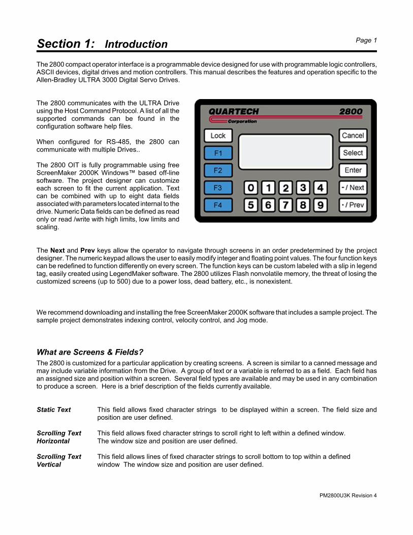
The 2800 compact operator interface is a programmable device designed for use with programmable logic controllers,ASCII devices, digital drives and motion controllers. This manual describes the features and operation specific to theAllen-Bradley ULTRA 3000 Digital Servo Drives.
The 2800 communicates with the ULTRA Driveusing the Host Command Protocol. A list of all thesupported commands can be found in theconfiguration software help files.
When configured for RS-485, the 2800 cancommunicate with multiple Drives..
The 2800 OIT is fully programmable using free ScreenMaker 2000K Windows™ based off-linesoftware. The project designer can customizeeach screen to fit the current application. Textcan be combined with up to eight data fieldsassociated with parameters located internal to thedrive. Numeric Data fields can be defined as readonly or read /write with high limits, low limits andscaling.
The Next and Prev keys allow the operator to navigate through screens in an order predetermined by the projectdesigner. The numeric keypad allows the user to easily modify integer and floating point values. The four function keyscan be redefined to function differently on every screen. The function keys can be custom labeled with a slip in legendtag, easily created using LegendMaker software. The 2800 utilizes Flash nonvolatile memory, the threat of losing thecustomized screens (up to 500) due to a power loss, dead battery, etc., is nonexistent.
We recommend downloading and installing the free ScreenMaker 2000K software that includes a sample project. Thesample project demonstrates indexing control, velocity control, and Jog mode.
What are Screens & Fields?
The 2800 is customized for a particular application by creating screens. A screen is similar to a canned message andmay include variable information from the Drive. A group of text or a variable is referred to as a field. Each field hasan assigned size and position within a screen. Several field types are available and may be used in any combinationto produce a screen. Here is a brief description of the fields currently available.
Static Text This field allows fixed character strings to be displayed within a screen. The field size andposition are user defined.
Scrolling Text This field allows fixed character strings to scroll right to left within a defined window.Horizontal The window size and position are user defined.
Scrolling Text This field allows lines of fixed character strings to scroll bottom to top within a definedVertical window The window size and position are user defined.
PM2800U3K Revision 4
Section 1: Introduction Page 2
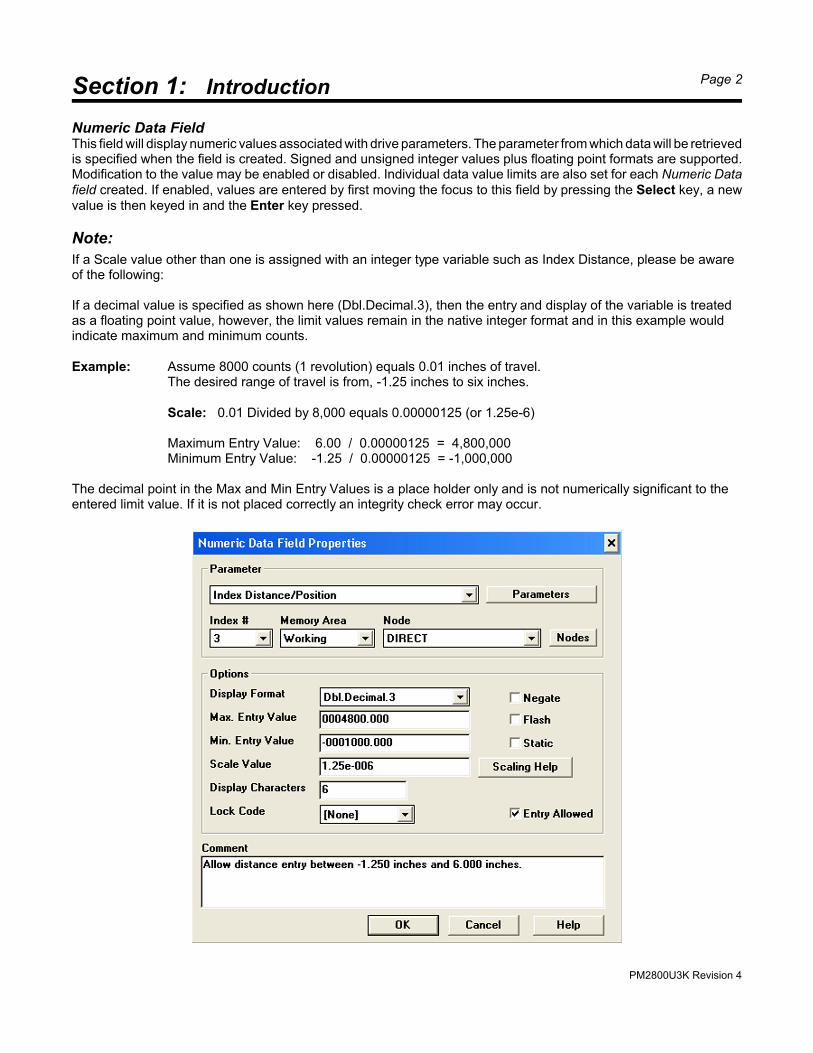
Numeric Data FieldThis field will display numeric values associated with drive parameters. The parameter from which data will be retrievedis specified when the field is created. Signed and unsigned integer values plus floating point formats are supported.Modification to the value may be enabled or disabled. Individual data value limits are also set for each Numeric Datafield created. If enabled, values are entered by first moving the focus to this field by pressing the Select key, a newvalue is then keyed in and the Enter key pressed.
Note:
If a Scale value other than one is assigned with an integer type variable such as Index Distance, please be awareof the following:
If a decimal value is specified as shown here (Dbl.Decimal.3), then the entry and display of the variable is treatedas a floating point value, however, the limit values remain in the native integer format and in this example wouldindicate maximum and minimum counts.
Example: Assume 8000 counts (1 revolution) equals 0.01 inches of travel.The desired range of travel is from, -1.25 inches to six inches.
Scale: 0.01 Divided by 8,000 equals 0.00000125 (or 1.25e-6)
The decimal point in the Max and Min Entry Values is a place holder only and is not numerically significant to theentered limit value. If it is not placed correctly an integrity check error may occur.
PM2800U3K Revision 4
Section 1: Introduction Page 3
The Negate check box will force a positive entered value to be converted to a negative value before it is written to theUltra Drive. Likewise, when a negative value is read from the Ultra Drive it will be converted to a positive numberbefore it is displayed. The function would be used only when the variable must always be negative. For example, ifthe motor must always turn in the negative direction, the operator would not have to remember to press the negativekey when entering a speed, distance, or position.
Scaling Example: Since the drive returns the current motor velocity as a number of counts per second we can usea scale value to convert the displayed value to revolutions per minute (RPM).Scale Value = 1 / ( Counts per Revolution / 60 )
Scale Value = 1 / ( 8,000 / 60 ) Assume encoder producing 8,000 counts per revolution.Scale Value = 1 / 133.33333Scale Value = 0.0075 or 7.5e-3 This is the value into the Scale box.
If the 2800 has received a motor velocity value of 200,000.
RPM = Count Value Received x Scale ValueRPM = 200,000 x 0.0075RPM = 1500 This is the value displayed by the 2800
If the operator enters 750, the 2800 will write the value 100,000 to the Drive..
Raw Value = Entered value / Scale ValueRaw Value = 750 / 0.0075Raw Value = 100,000 This is the value written to the Ultra Drive.
Velocity Scaling: convert from Counts / Second to Revolutions / Minute.Scale value = 60 divided by encoder pulses per revolution.
Accel/Decel Scaling: convert from Counts / Second / Second to Revolutions / Second / SecondScale value = one divided by encoder pulses per revolution.
PM2800U3K Revision 4
Section 1: Introduction Page 4
Recipe Field
This field appears as fixed text within a screen. The field can be used in a two different ways.
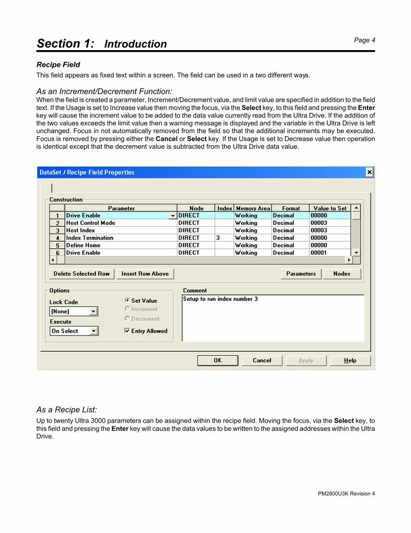
As an Increment/Decrement Function:When the field is created a parameter, Increment/Decrement value, and limit value are specified in addition to the fieldtext. If the Usage is set to Increase value then moving the focus, via the Select key, to this field and pressing the Enterkey will cause the increment value to be added to the data value currently read from the Ultra Drive. If the addition ofthe two values exceeds the limit value then a warning message is displayed and the variable in the Ultra Drive is leftunchanged. Focus in not automatically removed from the field so that the additional increments may be executed.Focus is removed by pressing either the Cancel or Select key. If the Usage is set to Decrease value then operationis identical except that the decrement value is subtracted from the Ultra Drive data value.
As a Recipe List:
Up to twenty Ultra 3000 parameters can be assigned within the recipe field. Moving the focus, via the Select key, tothis field and pressing the Enter key will cause the data values to be written to the assigned addresses within the UltraDrive.
PM2800U3K Revision 4
Section 1: Introduction Page 5
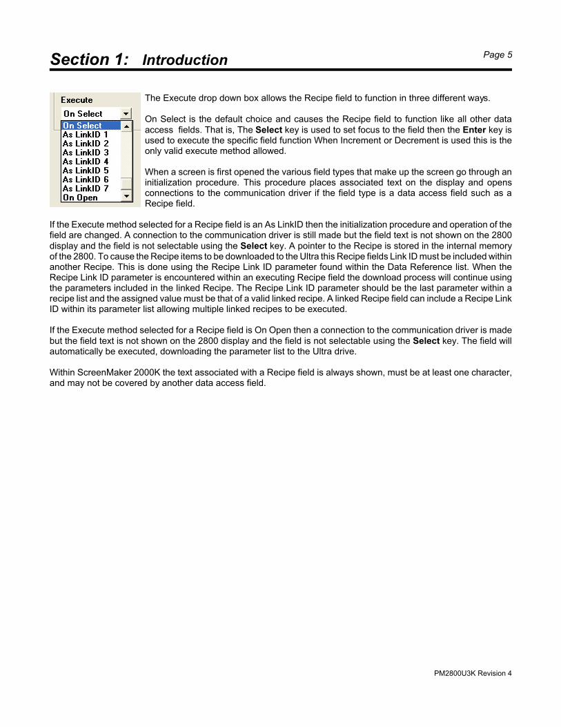
The Execute drop down box allows the Recipe field to function in three different ways.
On Select is the default choice and causes the Recipe field to function like all other dataaccess fields. That is, The Select key is used to set focus to the field then the Enter key isused to execute the specific field function When Increment or Decrement is used this is theonly valid execute method allowed.
When a screen is first opened the various field types that make up the screen go through aninitialization procedure. This procedure places associated text on the display and opensconnections to the communication driver if the field type is a data access field such as aRecipe field.
If the Execute method selected for a Recipe field is an As LinkID then the initialization procedure and operation of thefield are changed. A connection to the communication driver is still made but the field text is not shown on the 2800display and the field is not selectable using the Select key. A pointer to the Recipe is stored in the internal memoryof the 2800. To cause the Recipe items to be downloaded to the Ultra this Recipe fields Link ID must be included withinanother Recipe. This is done using the Recipe Link ID parameter found within the Data Reference list. When theRecipe Link ID parameter is encountered within an executing Recipe field the download process will continue usingthe parameters included in the linked Recipe. The Recipe Link ID parameter should be the last parameter within arecipe list and the assigned value must be that of a valid linked recipe. A linked Recipe field can include a Recipe LinkID within its parameter list allowing multiple linked recipes to be executed.
If the Execute method selected for a Recipe field is On Open then a connection to the communication driver is madebut the field text is not shown on the 2800 display and the field is not selectable using the Select key. The field willautomatically be executed, downloading the parameter list to the Ultra drive.
Within ScreenMaker 2000K the text associated with a Recipe field is always shown, must be at least one character,and may not be covered by another data access field.
PM2800U3K Revision 4
Section 1: Introduction Page 6
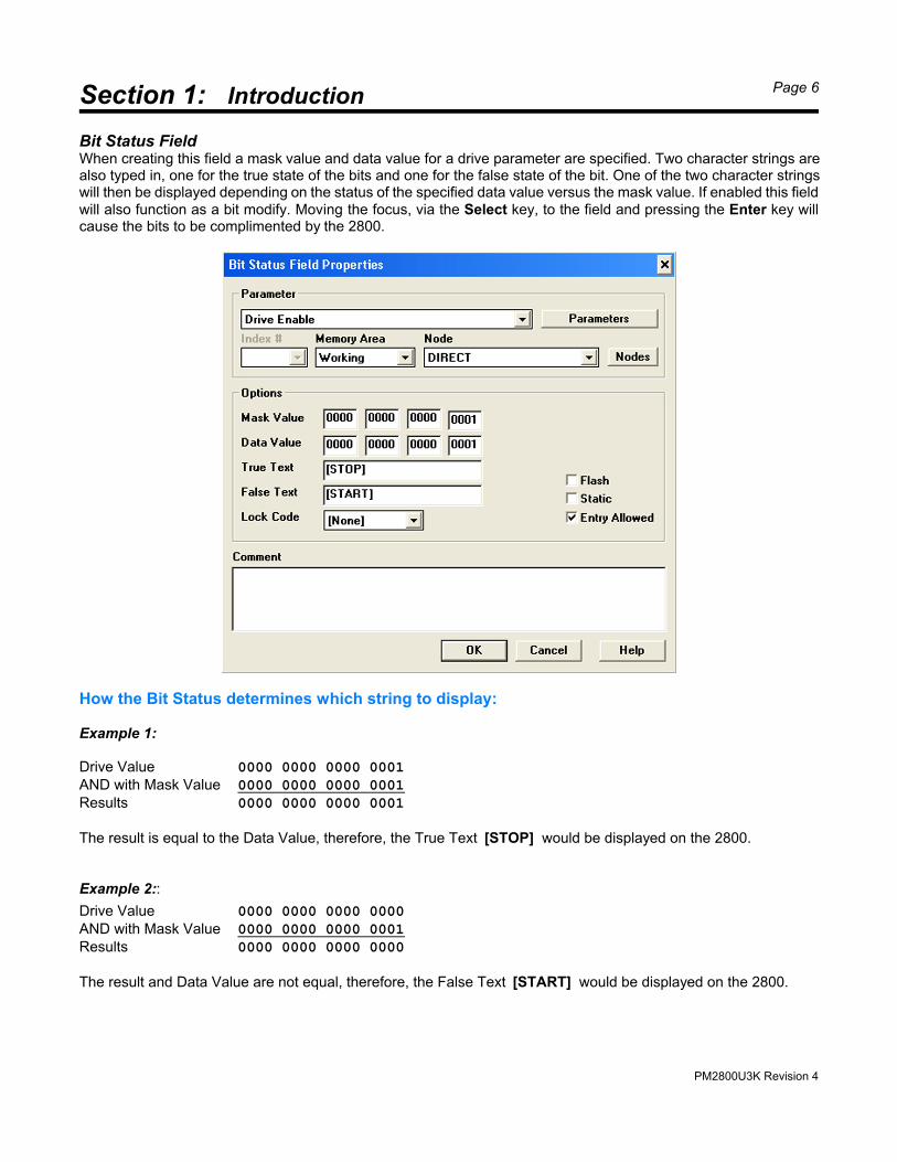
Bit Status FieldWhen creating this field a mask value and data value for a drive parameter are specified. Two character strings arealso typed in, one for the true state of the bits and one for the false state of the bit. One of the two character stringswill then be displayed depending on the status of the specified data value versus the mask value. If enabled this fieldwill also function as a bit modify. Moving the focus, via the Select key, to the field and pressing the Enter key willcause the bits to be complimented by the 2800.
How the Bit Status determines which string to display:
Example 1:
Drive Value 0000 0000 0000 0001AND with Mask Value 0000 0000 0000 0001Results 0000 0000 0000 0001
The result is equal to the Data Value, therefore, the True Text [STOP] would be displayed on the 2800.
Example 2::
Drive Value 0000 0000 0000 0000AND with Mask Value 0000 0000 0000 0001Results 0000 0000 0000 0000
The result and Data Value are not equal, therefore, the False Text [START] would be displayed on the 2800.
PM2800U3K Revision 4
Section 1: Introduction Page 7
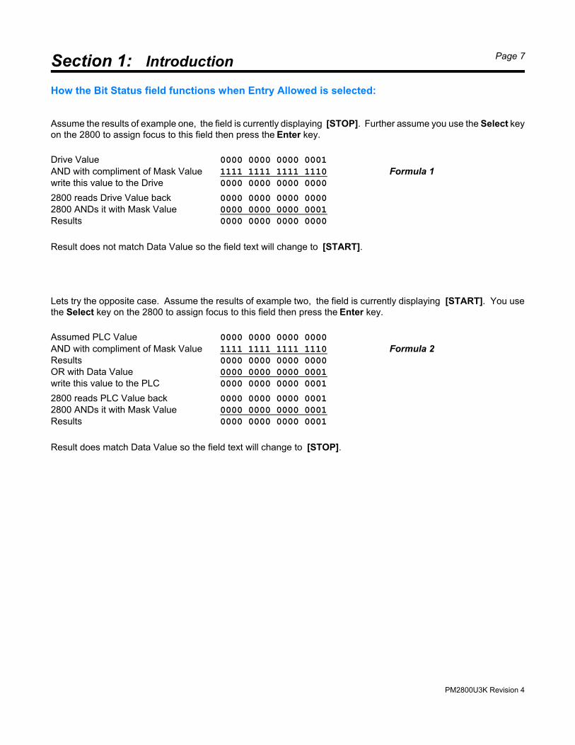
How the Bit Status field functions when Entry Allowed is selected:
Assume the results of example one, the field is currently displaying [STOP]. Further assume you use the Select keyon the 2800 to assign focus to this field then press the Enter key.
Drive Value 0000 0000 0000 0001
AND with compliment of Mask Value 1111 1111 1111 1110 Formula 1write this value to the Drive 0000 0000 0000 0000
2800 reads Drive Value back 0000 0000 0000 00002800 ANDs it with Mask Value 0000 0000 0000 0001Results 0000 0000 0000 0000
Result does not match Data Value so the field text will change to [START].
Lets try the opposite case. Assume the results of example two, the field is currently displaying [START]. You usethe Select key on the 2800 to assign focus to this field then press the Enter key.
Assumed PLC Value 0000 0000 0000 0000
AND with compliment of Mask Value 1111 1111 1111 1110 Formula 2Results 0000 0000 0000 0000OR with Data Value 0000 0000 0000 0001write this value to the PLC 0000 0000 0000 0001
2800 reads PLC Value back 0000 0000 0000 00012800 ANDs it with Mask Value 0000 0000 0000 0001Results 0000 0000 0000 0001
Result does match Data Value so the field text will change to [STOP].
PM2800U3K Revision 4
Section 1: Introduction Page 8
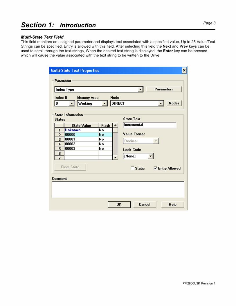
Multi-State Text FieldThis field monitors an assigned parameter and displays text associated with a specified value. Up to 25 Value/TextStrings can be specified. Entry is allowed with this field. After selecting this field the Next and Prev keys can beused to scroll through the text strings, When the desired text string is displayed, the Enter key can be pressedwhich will cause the value associated with the text string to be written to the Drive.
PM2800U3K Revision 4
Section 1: Introduction Page 9
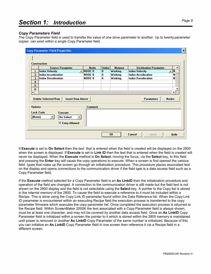
Copy Parameters FieldThe Copy Parameter field is used to transfer the value of one drive parameter to another. Up to twenty parametercopies can exist within a single Copy Parameter field.
If Execute is set to On Select then the text that is entered when the field is created will be displayed on the 2800when the screen is displayed. If Execute is set to Link ID then the text that is entered when the field is created willnever be displayed. When the Execute method is On Select, moving the focus, via the Select key, to this fieldand pressing the Enter key will cause the copy operations to execute. When a screen is first opened the variousfield types that make up the screen go through an initialization procedure. This procedure places associated texton the display and opens connections to the communication driver if the field type is a data access field such as aCopy Parameter field.
If the Execute method selected for a Copy Parameter field is an As LinkID then the initialization procedure andoperation of the field are changed. A connection to the communication driver is still made but the field text is notshown on the 2800 display and the field is not selectable using the Select key. A pointer to the Copy list is storedin the internal memory of the 2800. To cause the field to execute a reference to it must be included within aRecipe. This is done using the Copy Link ID parameter found within the Data Reference list. When the Copy LinkID parameter is encountered within an executing Recipe field the execution process is transferred to the copyparameter firmware which executes the copy parameter list. Once completed the execution process is returned tothe Recipe field. Within ScreenMaker 2000K the text associated with a Copy Parameter field is always shown,must be at least one character, and may not be covered by another data access field. Once an As LinkID CopyParameter field is initialized within a screen the pointer to it which is stored within the 2800 memory is maintaineduntil power is removed or another As LinkID Copy Parameter of the same number is initialized. Because of thisyou can initialize an As LinkID Copy Parameter field in one screen then reference it via a Recipe field in adifferent screen.
PM2800U3K Revision 4
Section 1: Introduction Page 10
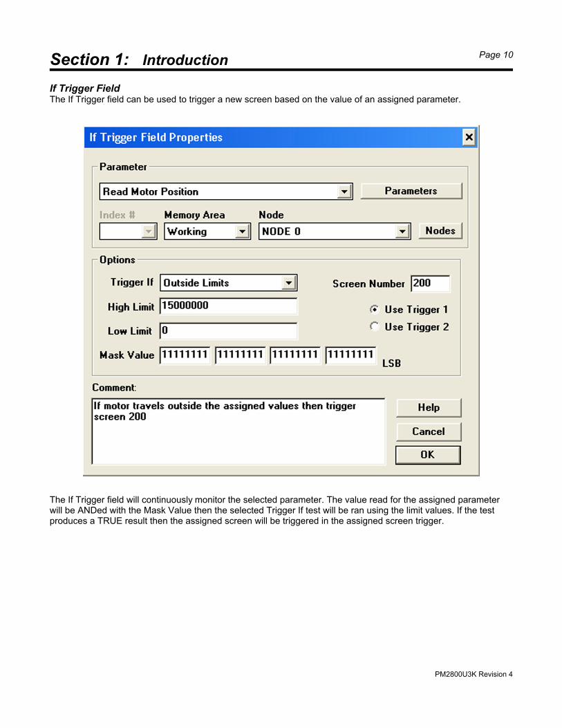
If Trigger FieldThe If Trigger field can be used to trigger a new screen based on the value of an assigned parameter.
The If Trigger field will continuously monitor the selected parameter. The value read for the assigned parameterwill be ANDed with the Mask Value then the selected Trigger If test will be ran using the limit values. If the testproduces a TRUE result then the assigned screen will be triggered in the assigned screen trigger.
PM2800U3K Revision 4
Section 2: Loading Driver Firmware Page 11
The 2800 is shipped from the factory with manufacturing test code installed. The first step in commissioning the2800 is to load a communication driver into it. In this case the driver is for the Allen-Bradley ULTRA 3000 DigitalServo Drives.
The Communication Driver File is loaded into the 2800 using ScreenMaker 2000K configuration software runningon your personal computer. If you have not yet created a screen application simply open a new project.
The 2800 is connected to the personal computer is via a communication cable (Quartech cable 2136-10). Thespecifications for this cable can be found in Appendix A.
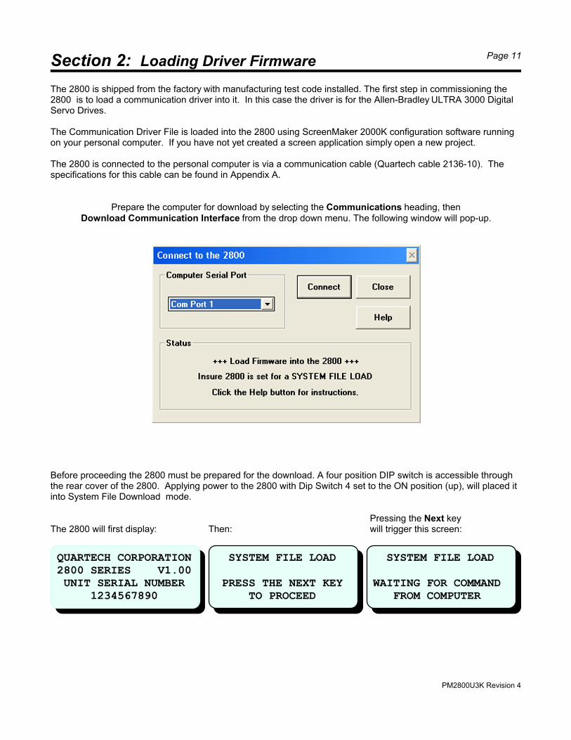
Prepare the computer for download by selecting the Communications heading, thenDownload Communication Interface from the drop down menu. The following window will pop-up.
Before proceeding the 2800 must be prepared for the download. A four position DIP switch is accessible throughthe rear cover of the 2800. Applying power to the 2800 with Dip Switch 4 set to the ON position (up), will placed itinto System File Download mode.
Pressing the Next keyThe 2800 will first display: Then: will trigger this screen:
QUARTECH CORPORATION2800 SERIES V1.00 UNIT SERIAL NUMBER 1234567890
SYSTEM FILE LOAD PRESS THE NEXT KEY TO PROCEED
SYSTEM FILE LOAD
WAITING FOR COMMAND FROM COMPUTER
PM2800U3K Revision 4
Section 2: Loading Driver Firmware Page 12
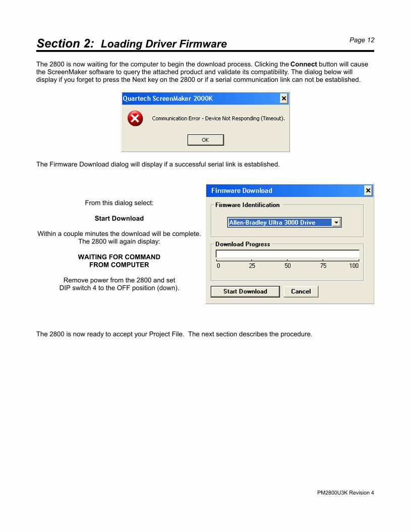
The 2800 is now waiting for the computer to begin the download process. Clicking the Connect button will causethe ScreenMaker software to query the attached product and validate its compatibility. The dialog below willdisplay if you forget to press the Next key on the 2800 or if a serial communication link can not be established.
The Firmware Download dialog will display if a successful serial link is established.
From this dialog select:
Start Download
Within a couple minutes the download will be complete.The 2800 will again display:
WAITING FOR COMMANDFROM COMPUTER
Remove power from the 2800 and setDIP switch 4 to the OFF position (down).
The 2800 is now ready to accept your Project File. The next section describes the procedure.
PM2800U3K Revision 4
Section 3: Loading Project Files Page 13
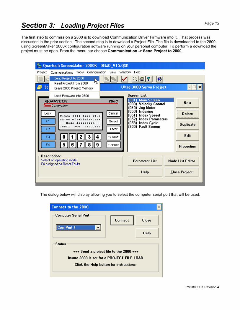
The first step to commission a 2800 is to download Communication Driver Firmware into it. That process wasdiscussed in the prior section. The second step is to download a Project File. The file is downloaded to the 2800using ScreenMaker 2000k configuration software running on your personal computer. To perform a download theproject must be open. From the menu bar choose Communication -> Send Project to 2800.
The dialog below will display allowing you to select the computer serial port that will be used.
PM2800U3K Revision 4
Section 3: Loading Project Files Page 14
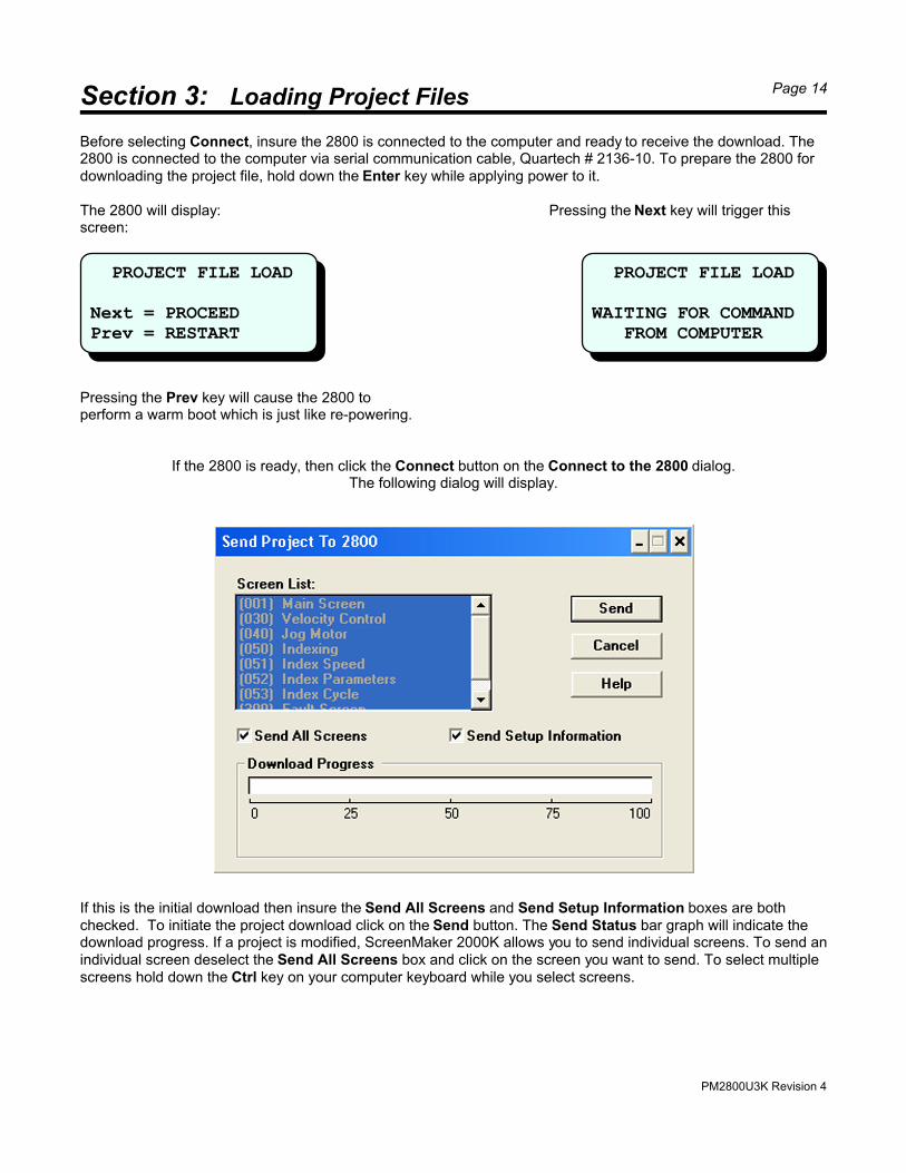
PROJECT FILE LOAD
Next = PROCEEDPrev = RESTART
PROJECT FILE LOAD
WAITING FOR COMMAND FROM COMPUTER
Before selecting Connect, insure the 2800 is connected to the computer and ready to receive the download. The2800 is connected to the computer via serial communication cable, Quartech # 2136-10. To prepare the 2800 fordownloading the project file, hold down the Enter key while applying power to it.
The 2800 will display: Pressing the Next key will trigger thisscreen:
Pressing the Prev key will cause the 2800 toperform a warm boot which is just like re-powering.
If the 2800 is ready, then click the Connect button on the Connect to the 2800 dialog.The following dialog will display.
If this is the initial download then insure the Send All Screens and Send Setup Information boxes are bothchecked. To initiate the project download click on the Send button. The Send Status bar graph will indicate thedownload progress. If a project is modified, ScreenMaker 2000K allows you to send individual screens. To send anindividual screen deselect the Send All Screens box and click on the screen you want to send. To select multiplescreens hold down the Ctrl key on your computer keyboard while you select screens.
PM2800U3K Revision 4
Section 4: Screen Triggering Page 15
Assuming the 2800 has been successfully configured with both a Driver Firmware and an a Project it is ready fornormal operation. An appropriate communication cable must be connected between the 2800 and ULTRA Driver. The communication cable is available from Quartech and is shown in Appendix A. When power is applied the2800 will enter the normal Run Mode.
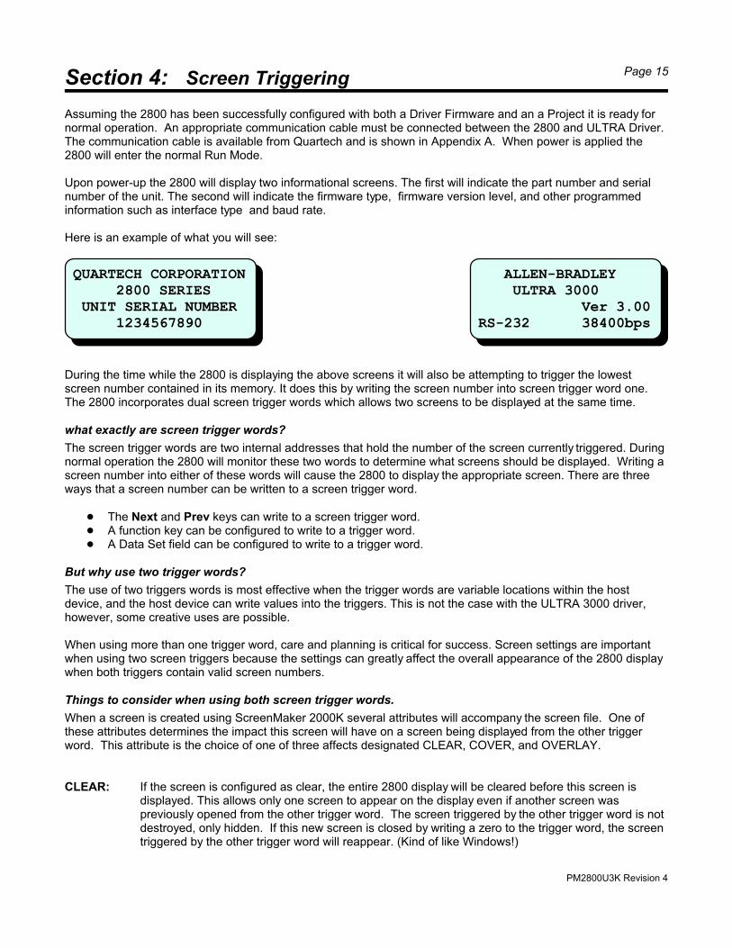
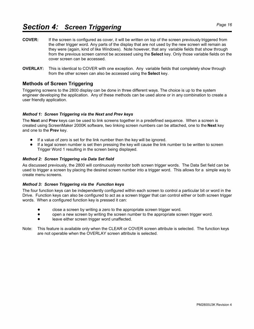
Upon power-up the 2800 will display two informational screens. The first will indicate the part number and serialnumber of the unit. The second will indicate the firmware type, firmware version level, and other programmedinformation such as interface type and baud rate.
Here is an example of what you will see:
During the time while the 2800 is displaying the above screens it will also be attempting to trigger the lowestscreen number contained in its memory. It does this by writing the screen number into screen trigger word one. The 2800 incorporates dual screen trigger words which allows two screens to be displayed at the same time.
what exactly are screen trigger words?
The screen trigger words are two internal addresses that hold the number of the screen currently triggered. Duringnormal operation the 2800 will monitor these two words to determine what screens should be displayed. Writing ascreen number into either of these words will cause the 2800 to display the appropriate screen. There are threeways that a screen number can be written to a screen trigger word.
! The Next and Prev keys can write to a screen trigger word.! A function key can be configured to write to a trigger word.! A Data Set field can be configured to write to a trigger word.
But why use two trigger words?
The use of two triggers words is most effective when the trigger words are variable locations within the hostdevice, and the host device can write values into the triggers. This is not the case with the ULTRA 3000 driver,however, some creative uses are possible.
When using more than one trigger word, care and planning is critical for success. Screen settings are importantwhen using two screen triggers because the settings can greatly affect the overall appearance of the 2800 displaywhen both triggers contain valid screen numbers.
Things to consider when using both screen trigger words.
When a screen is created using ScreenMaker 2000K several attributes will accompany the screen file. One ofthese attributes determines the impact this screen will have on a screen being displayed from the other triggerword. This attribute is the choice of one of three affects designated CLEAR, COVER, and OVERLAY.
CLEAR: If the screen is configured as clear, the entire 2800 display will be cleared before this screen isdisplayed. This allows only one screen to appear on the display even if another screen waspreviously opened from the other trigger word. The screen triggered by the other trigger word is notdestroyed, only hidden. If this new screen is closed by writing a zero to the trigger word, the screentriggered by the other trigger word will reappear. (Kind of like Windows!)
QUARTECH CORPORATION 2800 SERIES UNIT SERIAL NUMBER 1234567890
ALLEN-BRADLEY ULTRA 3000 Ver 3.00RS-232 38400bps
PM2800U3K Revision 4
Section 4: Screen Triggering Page 16
COVER: If the screen is configured as cover, it will be written on top of the screen previously triggered fromthe other trigger word. Any parts of the display that are not used by the new screen will remain asthey were (again, kind of like Windows). Note however, that any variable fields that show throughfrom the previous screen cannot be accessed using the Select key. Only those variable fields on thecover screen can be accessed.
OVERLAY: This is identical to COVER with one exception. Any variable fields that completely show throughfrom the other screen can also be accessed using the Select key.
Methods of Screen Triggering
Triggering screens to the 2800 display can be done in three different ways. The choice is up to the systemengineer developing the application. Any of these methods can be used alone or in any combination to create auser friendly application.
Method 1: Screen Triggering via the Next and Prev keys
The Next and Prev keys can be used to link screens together in a predefined sequence. When a screen iscreated using ScreenMaker 2000K software, two linking screen numbers can be attached, one to the Next keyand one to the Prev key.
! If a value of zero is set for the link number then the key will be ignored.! If a legal screen number is set then pressing the key will cause the link number to be written to screen
Trigger Word 1 resulting in the screen being displayed.
Method 2: Screen Triggering via Data Set field
As discussed previously, the 2800 will continuously monitor both screen trigger words. The Data Set field can beused to trigger a screen by placing the desired screen number into a trigger word. This allows for a simple way tocreate menu screens.
Method 3: Screen Triggering via the Function keys
The four function keys can be independently configured within each screen to control a particular bit or word in theDrive. Function keys can also be configured to act as a screen trigger that can control either or both screen triggerwords. When a configured function key is pressed it can:
! close a screen by writing a zero to the appropriate screen trigger word.! open a new screen by writing the screen number to the appropriate screen trigger word.! leave either screen trigger word unaffected.
Note: This feature is available only when the CLEAR or COVER screen attribute is selected. The function keysare not operable when the OVERLAY screen attribute is selected.
PM2800U3K Revision 4
Section 5: Key Definitions Page 17
The 2800 keypad is made up of twenty tactile feedback keys used for navigation, control, and data entry.
Select Key
This key is used to select a variable field you want to modify or initiate action from. Within this document we referto this as “assigning focus”. Each time the Select key is pressed, a flashing block character will be displayed. Depending on the field type, the character will be over the left most character (Drive Data) or over the entire field(Data Set, Bit Status, Multi-State Text). As the Select key is pressed, focus will move from variable field tovariable field in the order that they were created. When the Select key is pressed and no additional variable fieldsexist, the flashing cursor will move off screen.
If the Select key is pressed but no variable fields areaccessible the following message will momentarily display.
Enter Key
This key is used to initiate the writing of a value to the Drive.
! After modifying the value in a Drive Data field, the Enter key is pressed to initiate the writing of the newvalue to the Drive. If writing is successful, focus will be removed from this field and the cursor will moveoff screen.
! If a Data Set field has been selected, pressing the Enter key will write the assigned value to the Drive. Ifwriting is successful, focus will be removed from this field and the cursor will move off screen. If morethan one variable is specified the message “WRITING RECIPE DATA” will appear on the display untilthe process is complete. If this field is configured as a Increment or Decrement type then after pressingthe Enter key the 2800 will first read the current value from the Drive, add or subtract the assigned valuethen write the new value back to the Drive. The focus will remain on this field until the Select keytransfers it or the Cancel key is pressed..
! If a Bit status field has been selected, pressing the Enter key will toggle the state of the target bits in theDrive which will also change the character string displayed. Focus will then be removed from the fieldand the cursor will move off screen.
! If a Multi-State Text field has been selected, pressing the Enter key will write the value associated withthe text currently displayed to the Drive. The Next and Prev keys are used to scroll between choicesoffered by the Multi-State Text field.
Cancel Key
This key is used exit or back out of an operation.
! If the Select key is being used to assign focus to a field, pressed the Cancel key will remove focus andmove the cursor off screen.
! If you are currently keying data into a field, pressing the Cancel key once will clear the entered field dataleaving only a cursor. You may begin entering a new value. Pressing the Cancel key twice in a row willremove focus from the field.
NO ENTRY ALLOWED IN THIS SCREEN
PM2800U3K Revision 4
Section 5: Key Definitions Page 18
-/Next & ./Prev Keys
These keys are dual function.
! If the Select key has not placed focus on any variable fields then the -/Next and ./Prev keys are usedfor navigation. When a screen is created using ScreenMaker 2000K the system engineer has the optionto assign a next and previous screen linking number. Refer to Section 4: Methods of Screen Triggering,to review this feature.
! If the Select key has been used to place focus on a Drive Data field then the minus and decimal pointfunction becomes active. Note however, these keys may be ignored if the field format does not supportnegative or decimal numbers. If focus has been placed on a Multi-State Text field then these keys allowsscrolling through the field choices.
Numeric Keys 0 through 9
These keys are used exclusively for entering values into Drive Data fields or entering field lock codes.
Lock Key
This key is used to access the global lock code activation / deactivation screen. The 2800 provides fifteen lockcodes that can be specified during setup. When a Drive variable field is created using ScreenMaker 2000K, thedesigner can assign one of the lock codes to the field. When an operator tries to access a locked field a screen willpop up that prompts them for the lock code. Using the Lock key to deactivate a lock code allows the operator toaccess any field that uses that lock code with out re-entering it each time the field is accessed. In other words, itacts as a global lock override. Security locks are discussed in detail in Section 6.
Function Keys
These four keys are programmable function keys that can be re-defined for each screen created for the 2800. There are four different configurations that can be made for a key, or a key may be disabled. Within each screenthe four keys may be configured differently. A function key can also be set to operate as a momentary pushbuttonswitch or maintained pushbutton switch. The configuration options are as follows:
Pushbutton This configuration is used exclusively with write only Drive parameters such as.
Define Home Position Reset Drive Reset Faults Start Index
Pressing the key will cause the assign function to be executed.
Selector Switch This configuration is used exclusively with the dual state variables such as: Drive Enable Pressing the key will toggle the variable between the “1" and “0" state
Screen Trigger This configuration allows the key to function as a screen trigger. Unlike the Next and Prev keys, this screen trigger can write to either Screen Trigger Word or both at the same time. For more information refer to Section 4, screen trigger method three.
PM2800U3K Revision 4
Section 5: Key Definitions Page 19
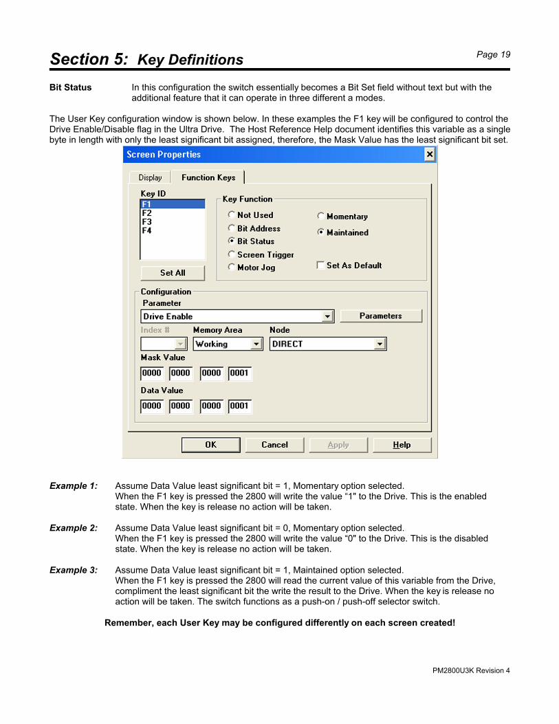
Bit Status In this configuration the switch essentially becomes a Bit Set field without text but with theadditional feature that it can operate in three different a modes.
The User Key configuration window is shown below. In these examples the F1 key will be configured to control the Drive Enable/Disable flag in the Ultra Drive. The Host Reference Help document identifies this variable as a singlebyte in length with only the least significant bit assigned, therefore, the Mask Value has the least significant bit set.
Example 1: Assume Data Value least significant bit = 1, Momentary option selected.When the F1 key is pressed the 2800 will write the value “1" to the Drive. This is the enabledstate. When the key is release no action will be taken.
Example 2: Assume Data Value least significant bit = 0, Momentary option selected.When the F1 key is pressed the 2800 will write the value “0" to the Drive. This is the disabledstate. When the key is release no action will be taken.
Example 3: Assume Data Value least significant bit = 1, Maintained option selected.When the F1 key is pressed the 2800 will read the current value of this variable from the Drive,compliment the least significant bit the write the result to the Drive. When the key is release noaction will be taken. The switch functions as a push-on / push-off selector switch.
Remember, each User Key may be configured differently on each screen created!
PM2800U3K Revision 4
Section 5: Key Definitions Page 20
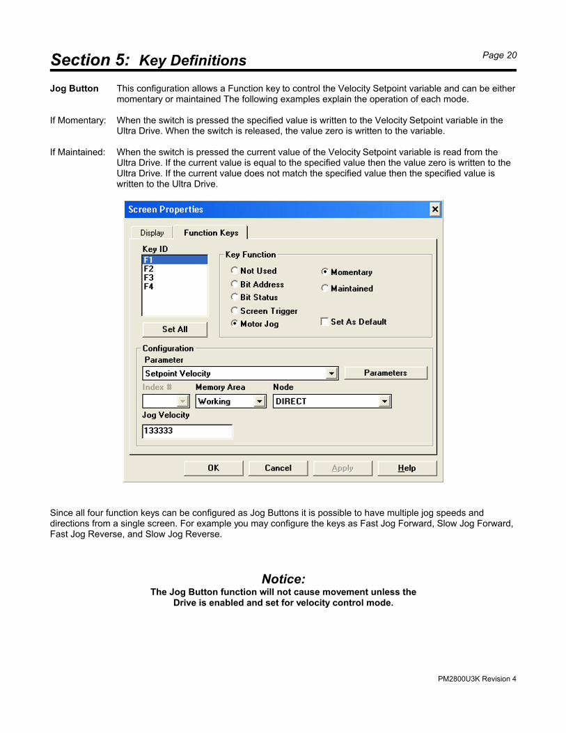
Jog Button This configuration allows a Function key to control the Velocity Setpoint variable and can be eithermomentary or maintained The following examples explain the operation of each mode.
If Momentary: When the switch is pressed the specified value is written to the Velocity Setpoint variable in theUltra Drive. When the switch is released, the value zero is written to the variable.
If Maintained: When the switch is pressed the current value of the Velocity Setpoint variable is read from theUltra Drive. If the current value is equal to the specified value then the value zero is written to theUltra Drive. If the current value does not match the specified value then the specified value iswritten to the Ultra Drive.
Since all four function keys can be configured as Jog Buttons it is possible to have multiple jog speeds anddirections from a single screen. For example you may configure the keys as Fast Jog Forward, Slow Jog Forward,Fast Jog Reverse, and Slow Jog Reverse.
Notice:The Jog Button function will not cause movement unless the
Drive is enabled and set for velocity control mode.
PM2800U3K Revision 4
Section 6: Drive Fault Monitoring Page 21
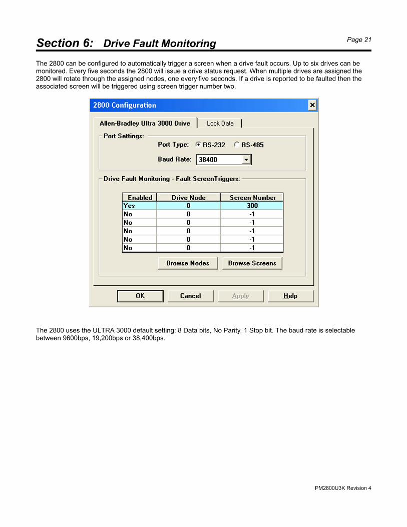
The 2800 can be configured to automatically trigger a screen when a drive fault occurs. Up to six drives can bemonitored. Every five seconds the 2800 will issue a drive status request. When multiple drives are assigned the2800 will rotate through the assigned nodes, one every five seconds. If a drive is reported to be faulted then theassociated screen will be triggered using screen trigger number two.
The 2800 uses the ULTRA 3000 default setting: 8 Data bits, No Parity, 1 Stop bit. The baud rate is selectablebetween 9600bps, 19,200bps or 38,400bps.
PM2800U3K Revision 4
Section 7: Security Locks Page 22
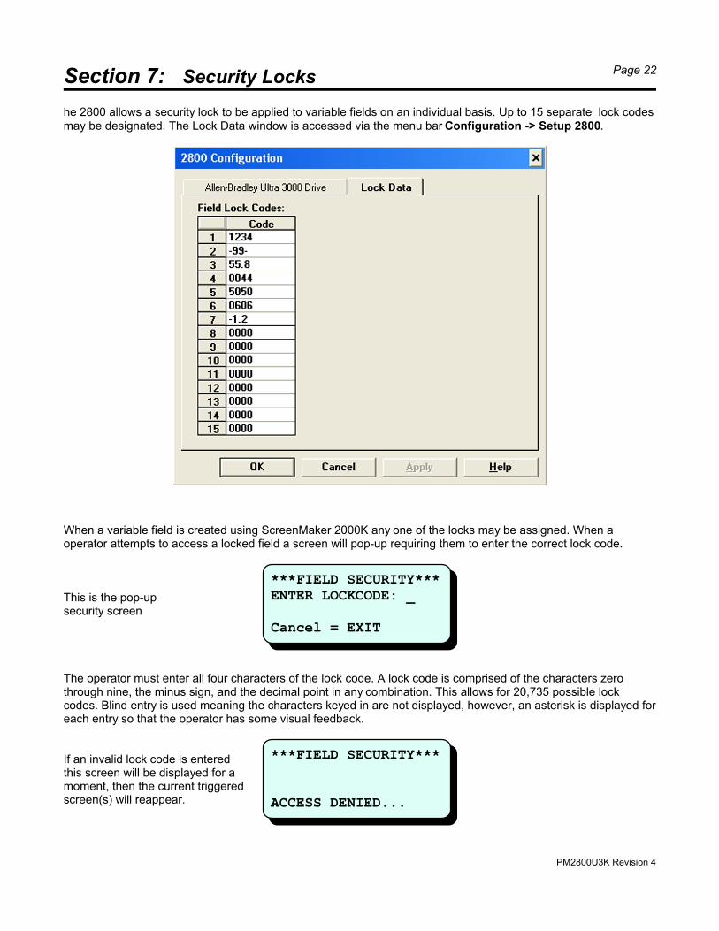
he 2800 allows a security lock to be applied to variable fields on an individual basis. Up to 15 separate lock codesmay be designated. The Lock Data window is accessed via the menu bar Configuration -> Setup 2800.
When a variable field is created using ScreenMaker 2000K any one of the locks may be assigned. When aoperator attempts to access a locked field a screen will pop-up requiring them to enter the correct lock code.
This is the pop-up security screen
The operator must enter all four characters of the lock code. A lock code is comprised of the characters zerothrough nine, the minus sign, and the decimal point in any combination. This allows for 20,735 possible lockcodes. Blind entry is used meaning the characters keyed in are not displayed, however, an asterisk is displayed foreach entry so that the operator has some visual feedback.
If an invalid lock code is enteredthis screen will be displayed for amoment, then the current triggered screen(s) will reappear.
***FIELD SECURITY***ENTER LOCKCODE: _
Cancel = EXIT
***FIELD SECURITY***
ACCESS DENIED...
PM2800U3K Revision 4
Section 8: LCD Contrast Adjustment Page 23
If the correct lock code is entered then access to the field is granted. Once the field is exited the lock is reset sothat re-entry into the field will require re-entry of the lock code.
Locks are generally used so that only authorized personnel can make changes to Drive variables. If an operator isrequired to modify a number of variable, or modify a single variable often then being required to re-enter the lockcode each time can become a burden.
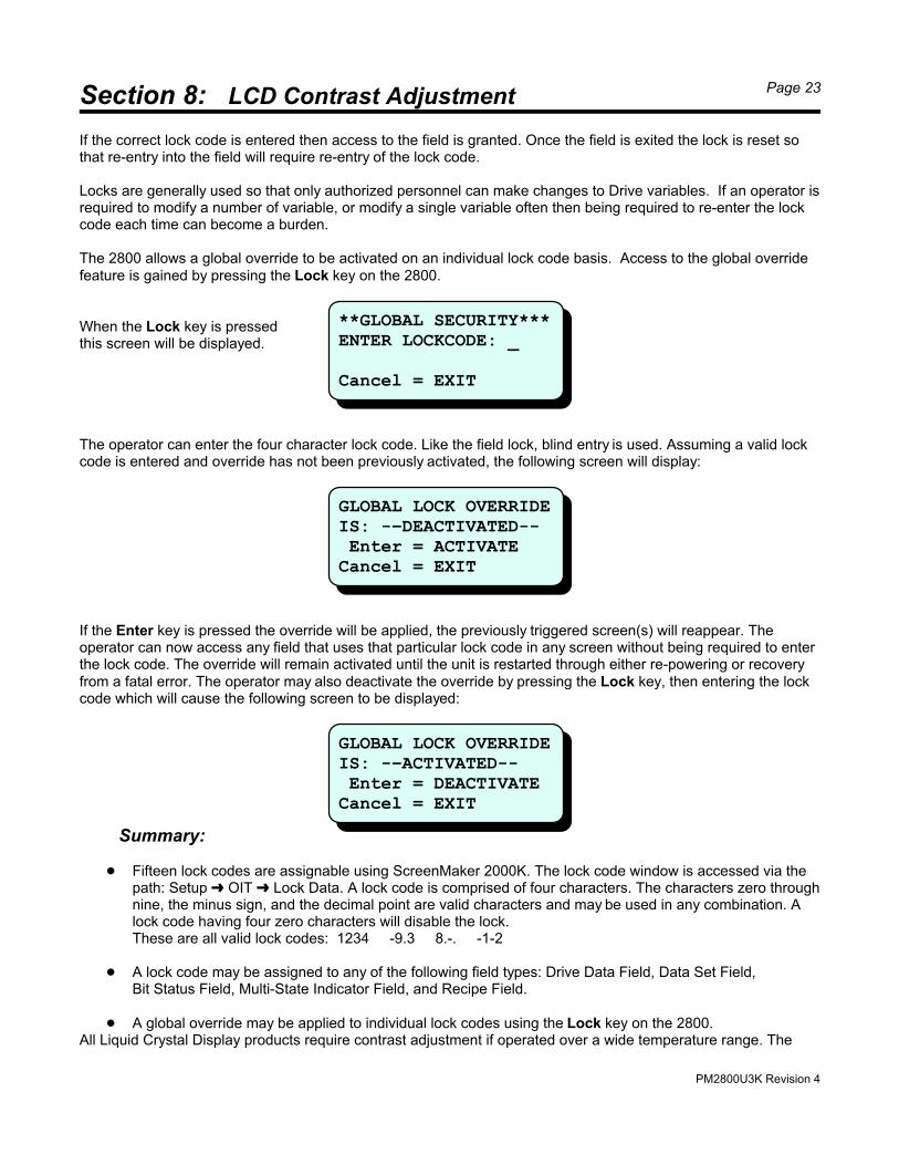
The 2800 allows a global override to be activated on an individual lock code basis. Access to the global overridefeature is gained by pressing the Lock key on the 2800.
When the Lock key is pressedthis screen will be displayed.
The operator can enter the four character lock code. Like the field lock, blind entry is used. Assuming a valid lockcode is entered and override has not been previously activated, the following screen will display:
If the Enter key is pressed the override will be applied, the previously triggered screen(s) will reappear. Theoperator can now access any field that uses that particular lock code in any screen without being required to enterthe lock code. The override will remain activated until the unit is restarted through either re-powering or recoveryfrom a fatal error. The operator may also deactivate the override by pressing the Lock key, then entering the lockcode which will cause the following screen to be displayed:
Summary:
! Fifteen lock codes are assignable using ScreenMaker 2000K. The lock code window is accessed via thepath: Setup º OIT º Lock Data. A lock code is comprised of four characters. The characters zero throughnine, the minus sign, and the decimal point are valid characters and may be used in any combination. Alock code having four zero characters will disable the lock.These are all valid lock codes: 1234 -9.3 8.-. -1-2
! A lock code may be assigned to any of the following field types: Drive Data Field, Data Set Field,Bit Status Field, Multi-State Indicator Field, and Recipe Field.
! A global override may be applied to individual lock codes using the Lock key on the 2800.All Liquid Crystal Display products require contrast adjustment if operated over a wide temperature range. The
**GLOBAL SECURITY***ENTER LOCKCODE: _
Cancel = EXIT
GLOBAL LOCK OVERRIDEIS: -–DEACTIVATED-- Enter = ACTIVATECancel = EXIT
GLOBAL LOCK OVERRIDEIS: -–ACTIVATED-- Enter = DEACTIVATECancel = EXIT
PM2800U3K Revision 4
Section 8: LCD Contrast Adjustment Page 24
2800 allows the LCD contrast to be adjusted from the front panel keypad.
Applicable to units with serial number prior to 55135.
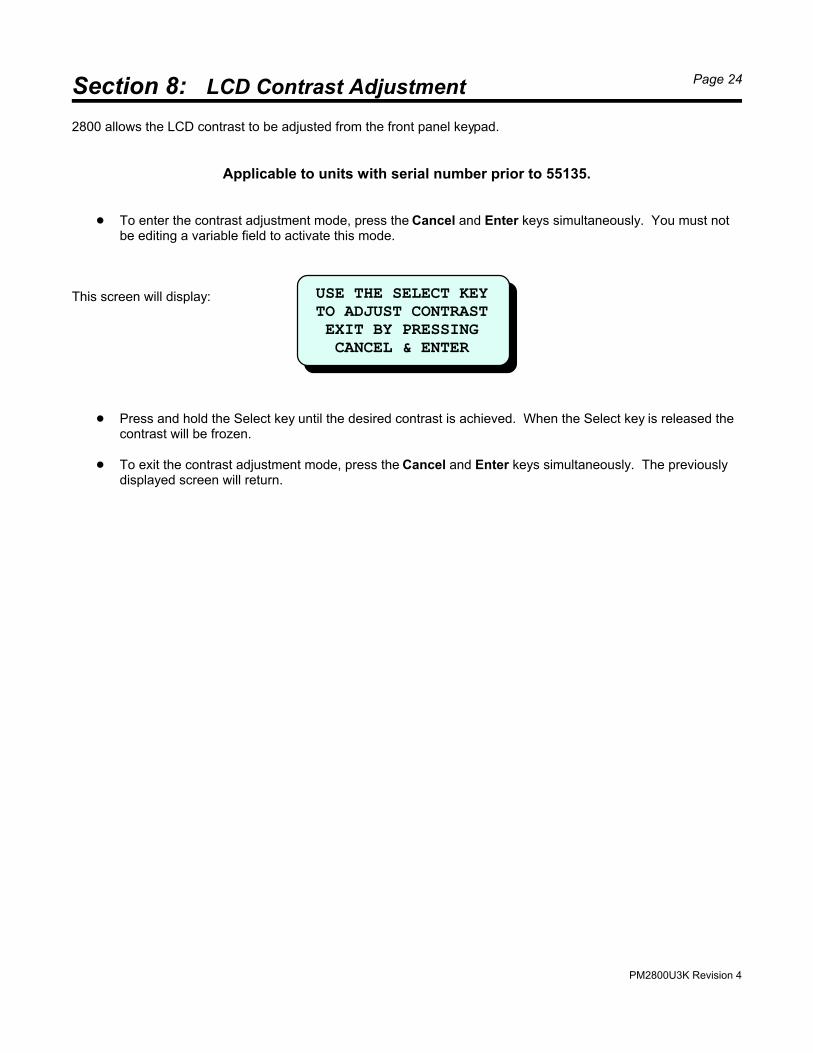
! To enter the contrast adjustment mode, press the Cancel and Enter keys simultaneously. You must notbe editing a variable field to activate this mode.
This screen will display:
! Press and hold the Select key until the desired contrast is achieved. When the Select key is released thecontrast will be frozen.
! To exit the contrast adjustment mode, press the Cancel and Enter keys simultaneously. The previouslydisplayed screen will return.
USE THE SELECT KEY TO ADJUST CONTRAST EXIT BY PRESSING CANCEL & ENTER
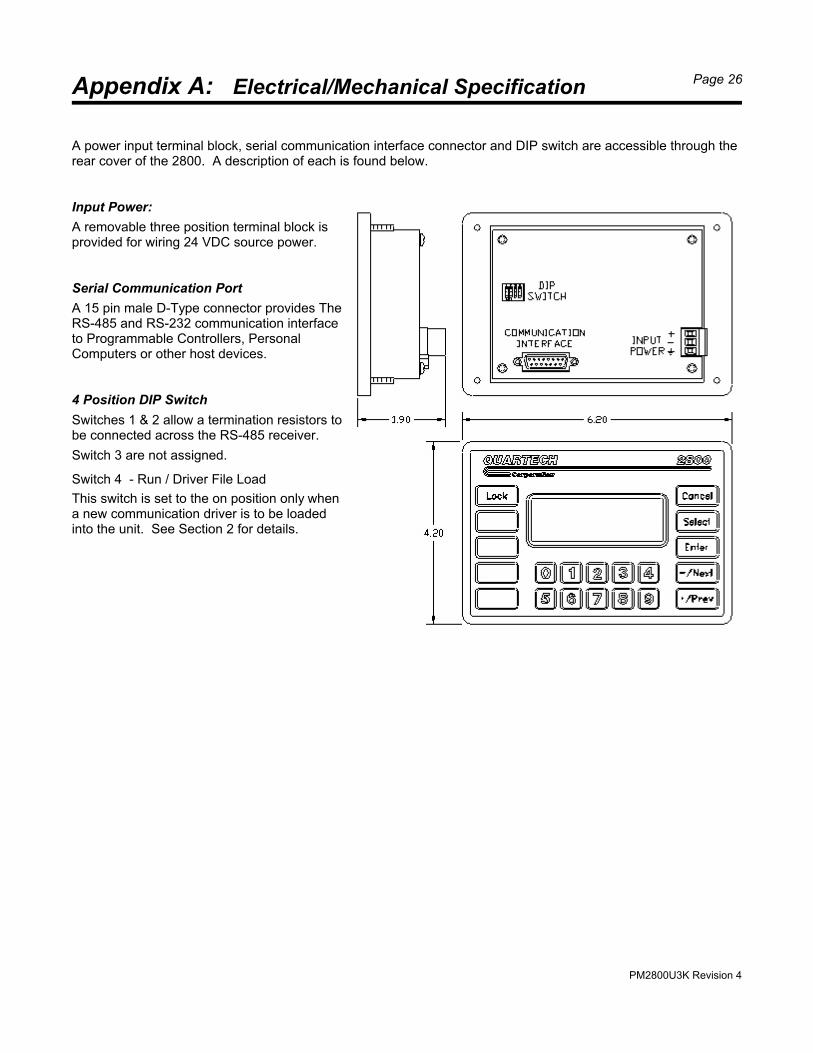
A power input terminal block, serial communication interface connector and DIP switch are accessible through therear cover of the 2800. A description of each is found below.
Input Power:
A removable three position terminal block isprovided for wiring 24 VDC source power.
Serial Communication Port
A 15 pin male D-Type connector provides TheRS-485 and RS-232 communication interfaceto Programmable Controllers, PersonalComputers or other host devices.
4 Position DIP Switch
Switches 1 & 2 allow a termination resistors tobe connected across the RS-485 receiver.
Switch 3 are not assigned.
Switch 4 - Run / Driver File Load
This switch is set to the on position only whena new communication driver is to be loadedinto the unit. See Section 2 for details.
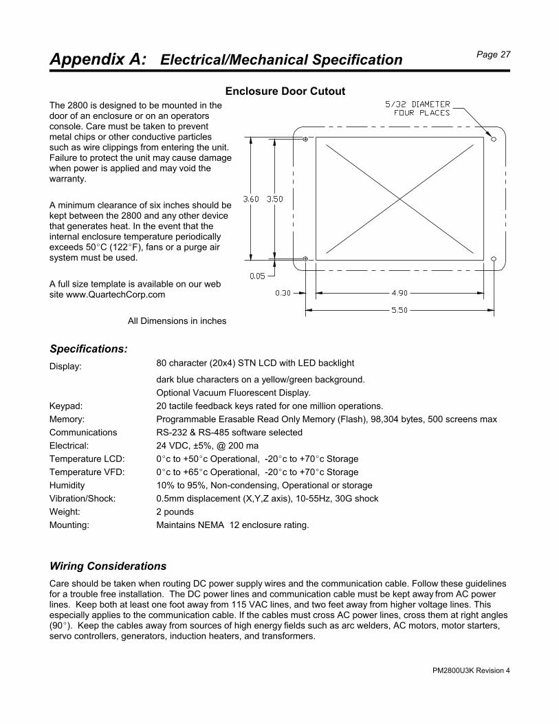
Enclosure Door CutoutThe 2800 is designed to be mounted in thedoor of an enclosure or on an operatorsconsole. Care must be taken to preventmetal chips or other conductive particlessuch as wire clippings from entering the unit.Failure to protect the unit may cause damagewhen power is applied and may void thewarranty.
A minimum clearance of six inches should bekept between the 2800 and any other devicethat generates heat. In the event that theinternal enclosure temperature periodicallyexceeds 50EC (122EF), fans or a purge airsystem must be used.
A full size template is available on our website www.QuartechCorp.com
All Dimensions in inches
Specifications:
Display: 80 character (20x4) STN LCD with LED backlight
dark blue characters on a yellow/green background.
Optional Vacuum Fluorescent Display.
Keypad: 20 tactile feedback keys rated for one million operations.
Memory: Programmable Erasable Read Only Memory (Flash), 98,304 bytes, 500 screens max
Communications RS-232 & RS-485 software selected
Electrical: 24 VDC, ±5%, @ 200 ma
Temperature LCD: 0Ec to +50Ec Operational, -20Ec to +70Ec Storage
Temperature VFD: 0Ec to +65Ec Operational, -20Ec to +70Ec Storage
Humidity 10% to 95%, Non-condensing, Operational or storage
Care should be taken when routing DC power supply wires and the communication cable. Follow these guidelinesfor a trouble free installation. The DC power lines and communication cable must be kept away from AC powerlines. Keep both at least one foot away from 115 VAC lines, and two feet away from higher voltage lines. Thisespecially applies to the communication cable. If the cables must cross AC power lines, cross them at right angles(90E). Keep the cables away from sources of high energy fields such as arc welders, AC motors, motor starters,servo controllers, generators, induction heaters, and transformers.
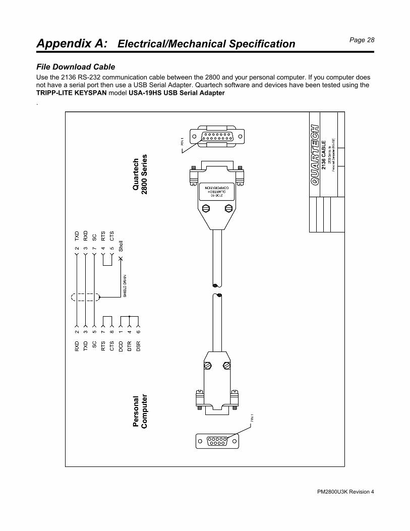
File Download CableUse the 2136 RS-232 communication cable between the 2800 and your personal computer. If you computer doesnot have a serial port then use a USB Serial Adapter. Quartech software and devices have been tested using theTRIPP-LITE KEYSPAN model USA-19HS USB Serial Adapter
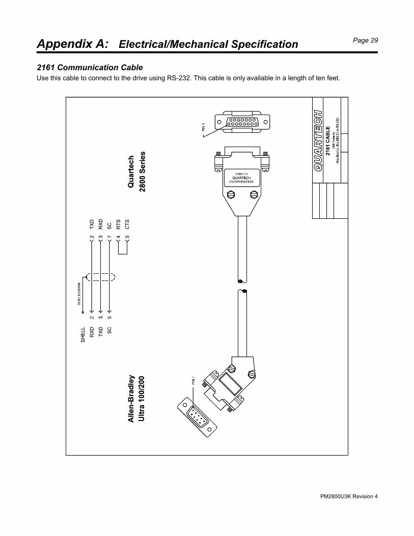
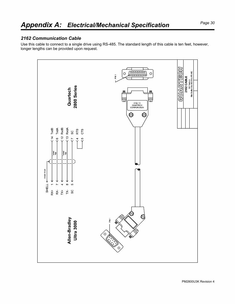
2162 Communication CableUse this cable to connect to a single drive using RS-485. The standard length of this cable is ten feet, however,longer lengths can be provided upon request.
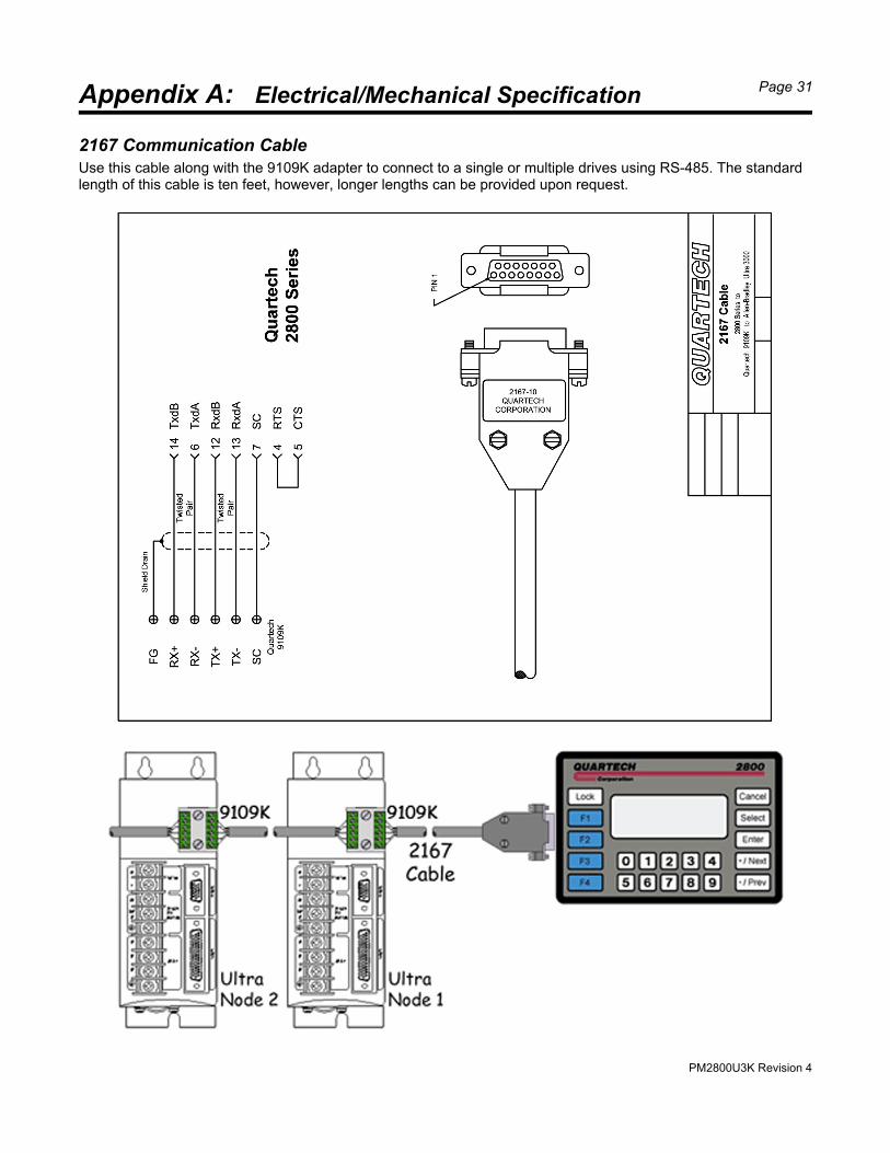
2167 Communication CableUse this cable along with the 9109K adapter to connect to a single or multiple drives using RS-485. The standardlength of this cable is ten feet, however, longer lengths can be provided upon request.
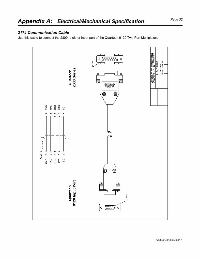
2174 Communication CableUse this cable to connect the 2800 to either input port of the Quartech 9120 Two Port Multiplexer.
PM2800U3K Revision 4
Appendix B: Error & Warning Messages Page 33
The 2800 is manufactured with pride and quality and is designed to provide years of trouble free operation. A vastnumber of diagnostic messages have been included it the 2800's firmware to inform the system engineer andoperator of any abnormality that may occur. These messages fit into three general categories which are:
Hardware Failure Configuration & Communication Errors Operational Status
When an abnormality is encountered a message will appear on the display indicating the nature of the problem. Some conditions will cause the 2800 to halt operation. Other conditions will cause a warning message to displaymomentarily. Still other conditions will cause a message to simply remain on the screen until the abnormality iscorrected. Below is a list of some of the messages that may appear.
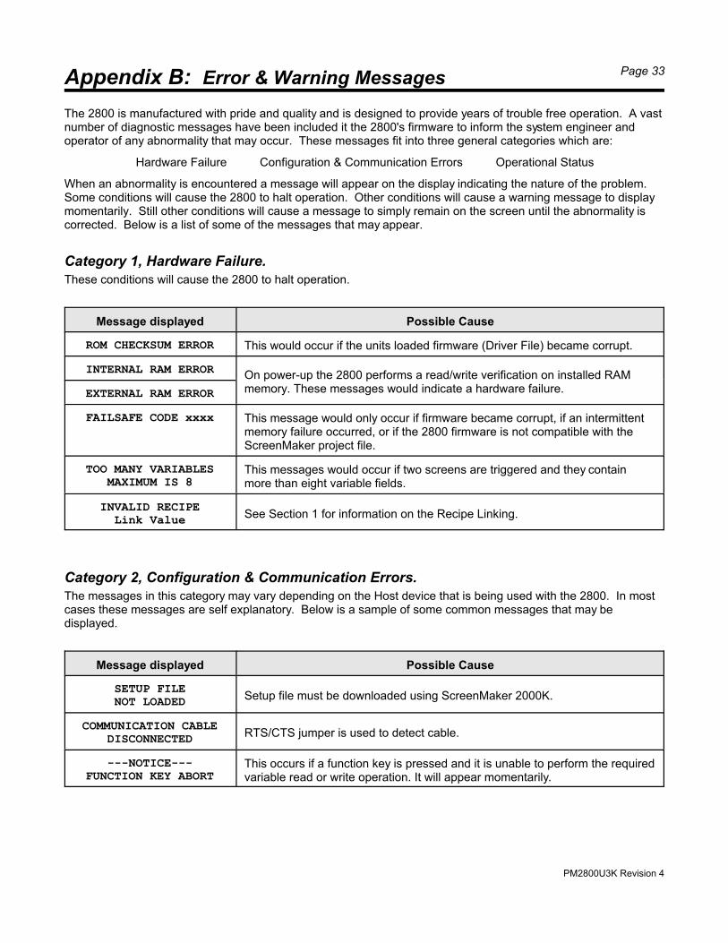
Category 1, Hardware Failure.These conditions will cause the 2800 to halt operation.
Message displayed Possible Cause
ROM CHECKSUM ERROR This would occur if the units loaded firmware (Driver File) became corrupt.
INTERNAL RAM ERROROn power-up the 2800 performs a read/write verification on installed RAMmemory. These messages would indicate a hardware failure.EXTERNAL RAM ERROR
FAILSAFE CODE xxxx This message would only occur if firmware became corrupt, if an intermittentmemory failure occurred, or if the 2800 firmware is not compatible with theScreenMaker project file.
TOO MANY VARIABLESMAXIMUM IS 8
This messages would occur if two screens are triggered and they containmore than eight variable fields.
INVALID RECIPELink Value See Section 1 for information on the Recipe Linking.
Category 2, Configuration & Communication Errors.The messages in this category may vary depending on the Host device that is being used with the 2800. In mostcases these messages are self explanatory. Below is a sample of some common messages that may bedisplayed.
Message displayed Possible Cause
SETUP FILENOT LOADED Setup file must be downloaded using ScreenMaker 2000K.
COMMUNICATION CABLEDISCONNECTED RTS/CTS jumper is used to detect cable.
---NOTICE---FUNCTION KEY ABORT
This occurs if a function key is pressed and it is unable to perform the requiredvariable read or write operation. It will appear momentarily.
PM2800U3K Revision 4
Appendix B: Error & Warning Messages Page 34
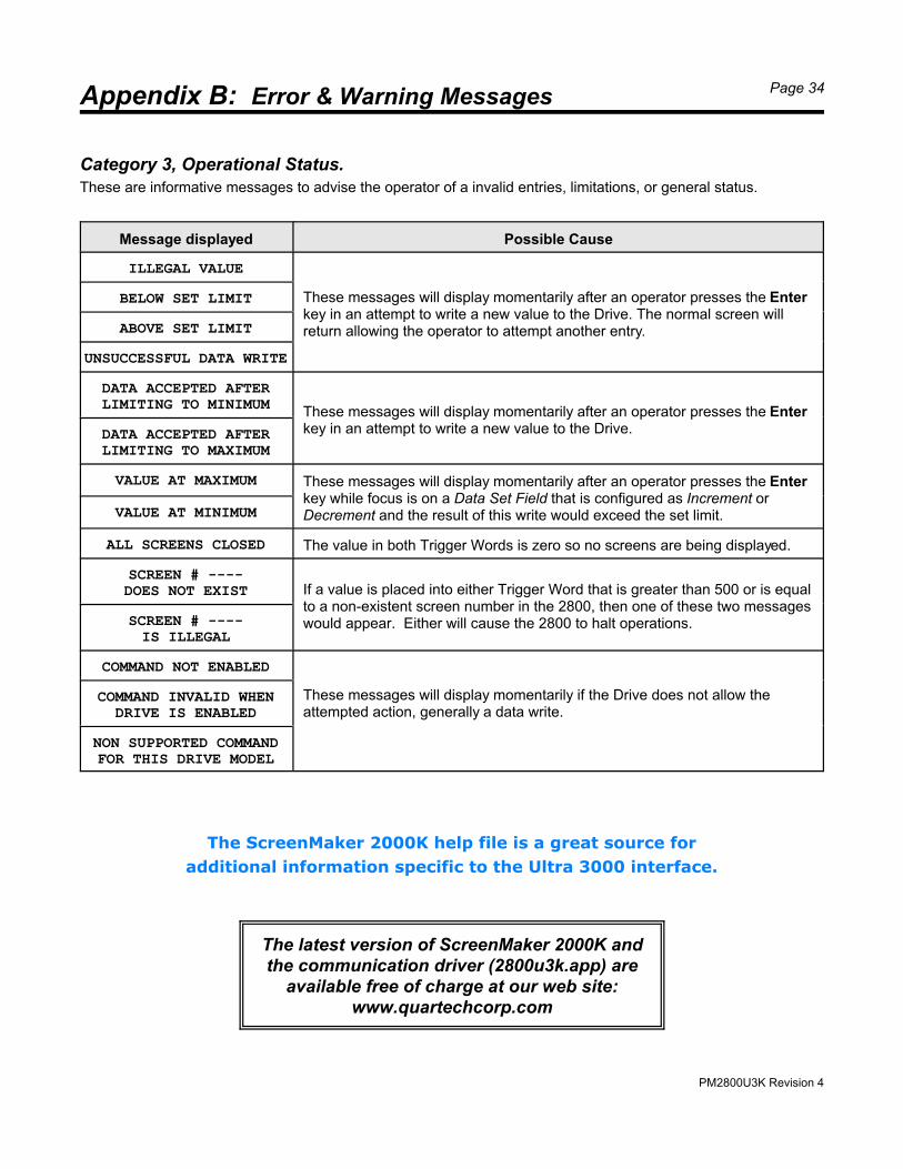
Category 3, Operational Status.These are informative messages to advise the operator of a invalid entries, limitations, or general status.
Message displayed Possible Cause
ILLEGAL VALUE
These messages will display momentarily after an operator presses the Enterkey in an attempt to write a new value to the Drive. The normal screen willreturn allowing the operator to attempt another entry.
BELOW SET LIMIT
ABOVE SET LIMIT
UNSUCCESSFUL DATA WRITE
DATA ACCEPTED AFTERLIMITING TO MINIMUM
These messages will display momentarily after an operator presses the Enterkey in an attempt to write a new value to the Drive.DATA ACCEPTED AFTER
LIMITING TO MAXIMUM
VALUE AT MAXIMUM These messages will display momentarily after an operator presses the Enterkey while focus is on a Data Set Field that is configured as Increment orDecrement and the result of this write would exceed the set limit.VALUE AT MINIMUM
ALL SCREENS CLOSED The value in both Trigger Words is zero so no screens are being displayed.
SCREEN # ----DOES NOT EXIST If a value is placed into either Trigger Word that is greater than 500 or is equal
to a non-existent screen number in the 2800, then one of these two messageswould appear. Either will cause the 2800 to halt operations. SCREEN # ----
IS ILLEGAL
COMMAND NOT ENABLED
These messages will display momentarily if the Drive does not allow theattempted action, generally a data write.
COMMAND INVALID WHENDRIVE IS ENABLED
NON SUPPORTED COMMANDFOR THIS DRIVE MODEL
The ScreenMaker 2000K help file is a great source for
additional information specific to the Ultra 3000 interface.
The latest version of ScreenMaker 2000K andthe communication driver (2800u3k.app) are
available free of charge at our web site:www.quartechcorp.com