16
PRODUCTION OF FUEL CELL SYSTEMS
PRODUCTION OF FUEL CELL SYSTEMS

Gerd Krieger
Managing Director of the Fuel Cell Working Group
VDMA
The German Mechanical EngineeringIndustry Association (VDMA) representsmore than 3200 companies in themechanical and plant engineering sector.The Fuel Cell Working Group supportsmore than 50 leading manufacturers andsuppliers of fuel cells in the expansion ofthe industrial network and in the politicalrepresentation of interests. To this end,technical solutions for the optimization andcost reduction of fuel cell systems andcomponents as well as for theestablishment of series production arebeing developed in project groups.
PEM of RWTH Aachen University isconcerned with the production technologyof fuel cells. Within the mechanicalengineering sector, the field of activityranges from the cost-efficient production ofhydrogen-powered drive train componentsto innovative mobility solutions and overallemission reduction. Through national andinternational projects with small and largecompanies at different stages of the valuechain as well as participation in variousresearch projects, PEM offers extensiveexpertise.
Authors
VDMA Working Group Fuel Cells
PEM at RWTH Aachen
Any questions?
Please contact us!
Aachen, November 20201st Edition, Printed by
PEM of RWTH Aachen University and VDMA, ISBN: 978-3-947920-14-3
Chair of Production Engineering of E-Mobility Components (PEM)
RWTH Aachen University
Bohr 1252072 Aachen
www.pem.rwth-aachen.de
VDMA Working Group Fuel Cells
Friedrichstraße 95
10117 Berlin
bz.vdma.org
Philipp Reims, M. Sc.
Research Associate Fuel Cell
Peter Ayvaz, M. Sc. M. Sc.
Chief Engineer
Christoph Schön, M. Sc.
Group Lead Fuel Cell
Prof. Dr.-Ing. Achim Kampker
Institute Director

Overviewof PEM fuel cells
Fuel Cell System
Fuel Cell Stack
Range ExtenderPredominant Fuel Cell
Hydrogen-Storage
PEMFC
Power distribution
BatteryConverter
Converter
Main engine
AccelerationRecuperation
Hydrogen-Storage
PEMFC
Converter
Battery
Main engine
Converter
For automotive applications, two different drive strategies based forPEM fuel cellscan be distinguished. If the vehicle has a drive system dominated by the fuel cell,the driving power requirement is primarily covered by the fuel cell. An additionallithium-ion battery is installed to handle short-term power peaks. Alternatively,the fuel cell can be used as a so-called range extender. Here the fuel cellfunctions as an "onboard charging system" for the vehicle's lithium-ion battery,which is the main energy supply.
Fuel Cell Components
Stack productionComponent production System production
Automotive applications
In this brochure, manufacturing a polymer electrolyte membrane (PEM) fuel cellsystem is schematically illustrated by means of the individual production steps forstack and system manufacturing including the assembly.The individual PEM fuel cells are connected in series to in a fuel cell stack. Thestack and other electrical, mechanical and thermal components are assembled toform the fuel cell system.Depending on the system design, the number and dimensioning ofinterconnected fuel cells within a stack varies and so does the associatedperformance data of the peripheral components. Due to the large number ofdifferent product and process variants, comprehensive information on theprocess parameters is only possible to a limited extent and can be specified inmore detail in joint discussions with the PEM chair or the VDMA.
of PEM Fuel Cells

Wasserstoff-rezirkulation
Vehicle architectureof a PEM fuel cell vehicle
The architecture of the drive train of a Fuel Cell Electric Vehicle (FCEV) consists ofthe main components fuel cell system, hydrogen tanks, lithium-ion battery,electric motor and power electronics. While the battery, electric motor and powerelectronics are also part of a battery-powered vehicle, fuel cell system andhydrogen tanks are unique to an FCEV.While the hydrogen tank is usually made of carbon-fiber wrapped plastic, the fuelcell system consists of air, hydrogen and cooling circuits: In the air circuit, ambientair is first compressed and then humidified before being fed to the cathode sideof the fuel cell. The hydrogen on the anode side is supplied by a hydrogenblower as part of the hydrogen cycle, which controls the output of the entiresystem by supplying fresh hydrogen. The cooling circuit ensures that the reactionheat is dissipated and is necessary for the cold start capability at temperaturesbelow freezing point.
Lithium-ion battery
Hydrogen tanksElectric motors
Fuel cell stack
Compressor
Cooling system
Power electronics
System architecture
M
M
Air filtration and compression
Humidifation Powerelectronics
Hydrogen recirculation Pressurized H2 storage
Coolingcircuit
Elec
tro
lyte
Ano
de
Cat
hod
e
Turbine M Motor Valve/Choke Pump
H2-Tank Air Filter Humidifier Water Trap
Pressure Valve
Check Valve
The system architecture of a fuel cell system including functional peripheralcomponents is structured as follows:

Balance-of-Plant componentsof a PEM fuel cell system
Anode module:● Closed hydrogen circuit with
pressure-temperature control● Anode module as dosing unit for
supplying the anode andhydrogen recirculation
● Assurance of the operatingpressure and hydrogen purity
The components of a fuel cell system are holistically referred to as Balance-of-Plant (BoP). The individual components can be subdivided into threesuperordinate subsystems: anode module, cathode module, and cooling system.They ensure the functionality of the media circuits and are exemplarily illustratedbelow. Hydrogen storage is not shown here.
Coolant pump
Compressor
Humidifier
Control Unit
Anode modulePressureregulator
Filter
Pressure regulator
Air filterCathode module
Cooling system
Hydrogen
Coolant
Air
Frame
Cathode module:● Supply and treatment of the reactant oxygen by means of air filter, electrically
operated compressor and air humidifier● Oil-free turbocharger as air compressor, driven by reaction exhaust air, to
increase efficiency● Humidifier made of bundled or stacked separating membranes
Cooling system:● Temperature control of the fuel
cell by de-ionised coolant● Consisting of coolant pump,
coolant filter and pressureregulator
● Cooling power requirement ofthe stack up to 50% of thenominal stack capacity

Production processof a PEM fuel cell system
● Due to the small production volumes of fuel cells, there is currently nogenerally valid process chain for the series production of PEM fuel cellcomponents
● Production of a PEM fuel cell system can be divided into three superordinatesteps: component production, stack production and system production
● This brochure presents the process steps that constitute the currentstate of the art in the production of PEM fuel cell stacks and systems
● Production of the individual fuel cell components is explained in more detail ina separate brochure entitled "Production of Fuel Cell Components”
*Essential part of the brochure „Production of Fuel Cell Components“
Component production*:
BPP
Coating FormingSeparating &
CuttingJoining
LeakageTesting
Gasket application
MEAJoining &
Seperating
GD
LChoppingCarbon Fiber
Impreg-nating
GraphitizingWater-
proofing
CC
M
MixingSubgasketapplication
Hot Pressing &Decal Removing
Coating Decal &Drying
MPL application& Sintering
FormingCarbon Paper
Stac
kStacking & Preassembly
Compressing TensioningLeakageTesting
FinalizationBreak-in &
Testing
Stack production:
System production:
Syst
emBalance-of-Plant Assembly Electrical Integration End of Line-Testing
Process step Intermediate product End product

OverviewPEM fuel cell stack and system
Fuel Cell System
● The fuel cell stack and theBalance-of-Plant (BoP) componentsform the fuel cell system
● The BoP components consist of ananode and cathode module, a coolingsystem, a control unit and currentconductors
Fuel Cell Stack
● The fuel cell stack consists of anynumber of individual fuel cellsconnected in series and thus enablesscalable performance ranges
● In addition to the individual cells, afunctional stack consists of end plates,current collectors, distribution plate andmonitoring unit
● In practice, there are several ways oftensioning fuel cell stacks. For example,tension bands (top figure) or tensionrods (bottom figure) are used

● At the beginning of fuel cell stack production, the lower end plate and thelower current collector are pre-assembled
● An optional scanning step of product labels of the MEA (Membrane ElectrodeAssembly) and the BPP (Bipolar Plate) in the incoming goods departmentfacilitates later component traceability of the product
● MEA (here: 5-layer MEA), BPP and gaskets (if gaskets have not been appliedto BPP previously) are stacked on top of each other in a defined order: (1)BPP, (2) gasket, (3) MEA, (4) gasket, (5) BPP
● Finally, the upper current collector and the upper end plate with mediaaccesses are added
● The exact alignment of the individual components of the stack can beensured by guiding elements
Stacking and pre-assembly
Stack production
End plate
Current collector
Current collector
End plate
Gripping tool
Pick-and-placerobot
1000427BH934ZX8
SpecificBarcode
Component production System production
Stack production
• Stack height 1 – 2 mm per cell (depending on performance level)
• Accuracy of cell positioning
• Freedom from destruction
• Accuracy of component thickness: < 10 µm
• Cleanroom classification: ISO 8
• Pick-and-place robot for stacking process
• Fully automatic stacking by feeding systems
• Semi-automatic stacking by carousel devices
• Manual stacking
• Number of fuel cells: 2 – 10 Cells per kW
• Stacking speed: < 2,3 Seconds per component
• Component positioning accuracy: 0.1 mm / 100 µm
Process parameters & requirements
Influences on quality Quality criteria
Alternative technologies

● Compression takes place within a pressing device, for example a hydraulic press● By pressing the individual components, the various layers including gaskets are
compressed, and the stack is thus sealed● Contact resistances between the components are reduced by the compression● A regulation of the pressing force and the pressing path ensures sufficient
compression and avoids damage to the components through overloading● A uniform compression has a considerable influence on the later power density
as well as the lifetime of the stack
Compressing
Result
Compressed fuel cell stack
Punch
F
N
s
Force-path control
Hydraulic press
Stack productionComponent production System production
Stack production
• Accuracy of pressing force and path:max. +/- 2 %
• Cleanroom classification: ISO 8
• Traversing speed
• Positioning accuracy
• Stack height: 1 – 2 mm per cell (depending on performance level)
• Tightness
• Freedom from destruction
• Uniform pressure distribution
• Spindle press
• Hydraulic press
• Pneumatic press
• Servo-hydraulic press
• Press force: max. 160 kN
• Uniform pressure
• Pressing path (product-dependent)
• Process time: < 150 seconds per stack
Process parameters & requirements
Influences on quality Quality criteria
Alternative technologies
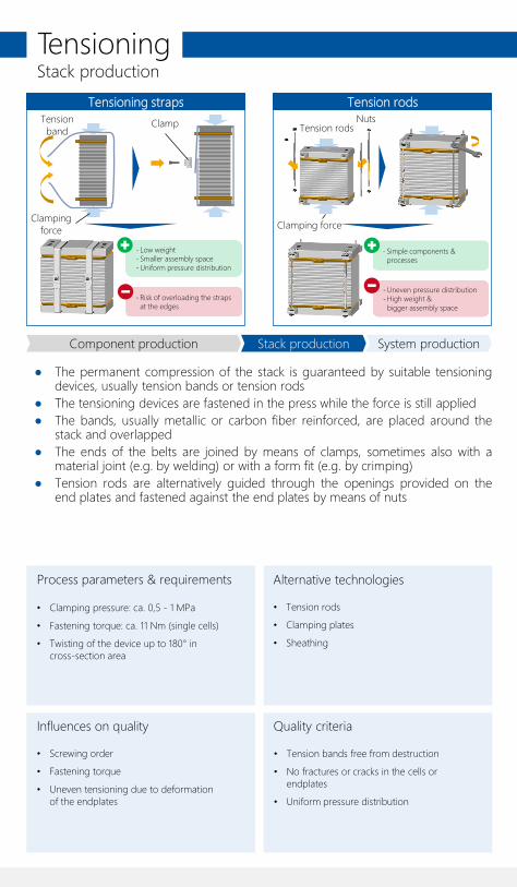
Tensioning strapsTension
bandClamp
- Risk of overloading the straps at the edges
- Low weight- Smaller assembly space- Uniform pressure distribution
Clamping force
Tension rods
- Uneven pressure distribution- High weight &
bigger assembly space
- Simple components & processes
Tension rodsNuts
Clamping force
● The permanent compression of the stack is guaranteed by suitable tensioningdevices, usually tension bands or tension rods
● The tensioning devices are fastened in the press while the force is still applied● The bands, usually metallic or carbon fiber reinforced, are placed around the
stack and overlapped● The ends of the belts are joined by means of clamps, sometimes also with a
material joint (e.g. by welding) or with a form fit (e.g. by crimping)● Tension rods are alternatively guided through the openings provided on the
end plates and fastened against the end plates by means of nuts
Tensioning
Stack productionComponent production System production
Stack production
Process parameters & requirements
Influences on quality Quality criteria
Alternative technologies
• Tension bands free from destruction
• No fractures or cracks in the cells or endplates
• Uniform pressure distribution
• Clamping pressure: ca. 0,5 - 1 MPa
• Fastening torque: ca. 11 Nm (single cells)
• Twisting of the device up to 180° in cross-section area
• Tension rods
• Clamping plates
• Sheathing
• Screwing order
• Fastening torque
• Uneven tensioning due to deformation of the endplates
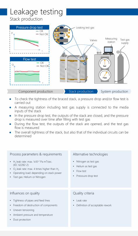
● To check the tightness of the braced stack, a pressure drop and/or flow test iscarried out
● A measuring station including test gas supply is connected to the mediainputs of the stack
● In the pressure drop test, the outputs of the stack are closed, and the pressuredrop is measured over time after filling with test gas
● During the flow test, the outputs of the stack are opened, and the test gasflow is measured
● The overall tightness of the stack, but also that of the individual circuits can bedetermined
Leakage testing
Measuring station
Test gas supply
Leaking test gas
Valves
Flow test
Q
t
Flow
bar
Pressure drop test
p
t
OKNot OK
Stack productionComponent production System production
Stack production
• Leak rate
• Definition of acceptable rework
• H2 leak rate: max. 1x10⁻² Pa m³/sec. (IEC 62282-2)
• O2 leak rate: max. 4 times higher than H2
• Operating load: depending on stack power
• Test gas: Helium or Nitrogen
• Nitrogen as test gas
• Helium as test gas
• Flow test
• Presssure drop test
• Tightness of pipes and feed lines
• Freedom of destruction of components
• Uneven tensioning
• Ambient pressure and temperature
• Dust protection
Process parameters & requirements
Influences on quality Quality criteria
Alternative technologies
OKNot OK

● A CVM unit (Cell Voltage Monitoring) is attached to the side of the stack tomonitor the voltage of the individual cells
● Individual contacts of the CVM unit are attached to the bipolar plates of thefuel cells using epoxy resins
● Busbars for the later HV (High Voltage) output cabling of the stack arescrewed to the current collectors
● The stack is inserted into a housing and the housing cover is mounted● The cover of the housing is also the distributor plate and contains all inputs
and outputs for media as well as connections for sensors and HV cabling
Finalization
Housing
CVM-Unit
Current collectors
Distributor plate
Contacts
Bipolar plate
Gasket
Epoxy resin
Stack production System production
Stack production
• Conductivity and correct reception of the individual cell voltages
• Serviceability with the possibility of opening the housing
• Dosing quantity of the epoxy resin
• Ensuring transport safety
• Positioning accuracy of the conductor ends
• Semi-automated assembly
• Measurement of the stack total voltage instead of individual cell voltages
• Wetting and quality of the epoxy resin
• Handling and safety regulations for employee inspection
Component production
Process parameters & requirements
Influences on quality Quality criteria
Alternative technologies
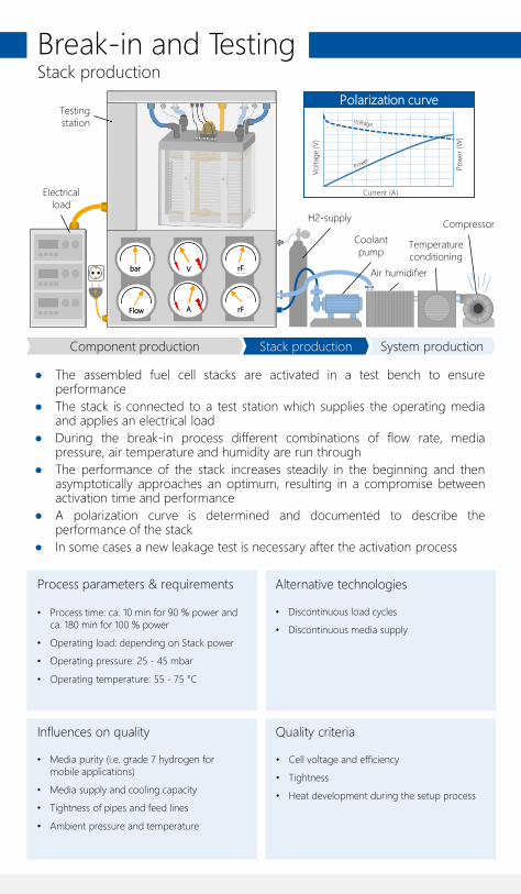
● The assembled fuel cell stacks are activated in a test bench to ensureperformance
● The stack is connected to a test station which supplies the operating mediaand applies an electrical load
● During the break-in process different combinations of flow rate, mediapressure, air temperature and humidity are run through
● The performance of the stack increases steadily in the beginning and thenasymptotically approaches an optimum, resulting in a compromise betweenactivation time and performance
● A polarization curve is determined and documented to describe theperformance of the stack
● In some cases a new leakage test is necessary after the activation process
Break-in and TestingStack production
Polarization curve
V
AFlow
bar rF
rF
Air humidifier
Temperature conditioning
Compressor
Coolant pump
H2-supply
Current (A)
Pow
er (
W)
Vo
ltag
e (V
)
Testing station
Electrical load
Stack production System production
• Cell voltage and efficiency
• Tightness
• Heat development during the setup process
• Process time: ca. 10 min for 90 % power and ca. 180 min for 100 % power
• Operating load: depending on Stack power
• Operating pressure: 25 - 45 mbar
• Operating temperature: 55 - 75 °C
• Discontinuous load cycles
• Discontinuous media supply
• Media purity (i.e. grade 7 hydrogen for mobile applications)
• Media supply and cooling capacity
• Tightness of pipes and feed lines
• Ambient pressure and temperature
Component production
Process parameters & requirements
Influences on quality Quality criteria
Alternative technologies

● The Balance-of-Plant components are connected to the fuel cell stack, forexample with the aid of a mounting frame
● To supply the entire system with hydrogen, the anode module (consisting ofhydrogen recirculation pump, pressure regulator and lines) is attached
● To ensure the necessary system cooling, the cooling system (consisting offilter, cooling water pump, pressure regulator and pipes) is installed
● The cathode module (consisting of compressor, air filter, humidifier, pressureregulator and pipes) is mounted to supply the entire system with air
● The control unit is mounted to control the media supply and thermalmanagement
Balance-of-Plant assembly
Compressor
Air humidifier
Control unit
Frame
Anode module
Pressure regulator
Coolant pumpFilter
Pressure regulator
Air filter
Cathode module
Cooling system
Hydrogen
Coolant
Air
Stack production System production
System production
• External integrity and technical cleanliness
• Firmly seated joints
• Correct positioning and cabling of peripheral devices
• Dismountability
• Assembly instructions including division into subassemblies
• Component design suitable for assembly (e.g. hole pattern in frame)
• Ensuring transport safety (cables, connections, protective flaps, etc.)
• Partial automation of the assembly possible
• Plug and screw connections
• Handling and safety regulations for employee inspection
• Inline measurement and testing technology of assembly
• Poka-Yoke design for protection against incorrect assembly
• Accessibility of the connection points
Component production
Process parameters & requirements
Influences on quality Quality criteria
Alternative technologies

● The previously mounted BoP components are connected to the mediaopenings of the stack via cables and pipes
● The control unit is connected to the individual BoP components● The HV output cabling is attached● In the last assembly step the wiring harness is mounted for later vehicle
integration
Electrical Integration
HV-cableWiring harness
Coolant linesAir tube
Completed fuel cell system
Stack production System production
System production
• External integrity and technical cleanliness
• Firmly seated joints
• Correct positioning and cabling of peripheral devices
• Dismountability
• Employee qualification for the assembly of flexible cables
• Employee qualification for assembly under high-voltage safety (> 60 V)
• Ensuring transport safety (cables, connections, protective flaps, etc.)
• Plug and screw connections
• Pressing on the hoses and lines
• Handling and safety regulations for employee inspection
• Accessibility of the connection points
• Poka-Yoke design for protection against faulty contacting
Component production
Process parameters & requirements
Influences on quality Quality criteria
Alternative technologies
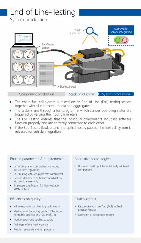
● The entire fuel cell system is tested on an End of Line (EoL) testing stationtogether with all connected media and aggregates
● The system runs through a test program in which various operating states aretriggered by varying the input parameters
● The EoL-Testing ensures that the individual components including softwarefunction properly and are correctly connected to each other
● If the EoL-Test is flawless and the optical test is passed, the fuel cell system isreleased for vehicle integration
End of Line-TestingSystem production
Visual inspection
Approval for vehicle integration
V A
Flow bar
rF T
EoL-Testing station
Stromstärke (A)
Leis
tung
(W)
Span
nung
(V)
Electrical load
Stack production System production
• Factory Acceptance Test (FAT) as final product release
• Definition of acceptable rework
• List of criteria for comprehensive testing (no uniform regulation)
• EoL-Testing with setup process parameters
• Defined delivery condition in coordination with vehicle assembly
• Employee qualification for high-voltage safety (> 60 V)
• Upstream testing of the individual peripheral components
• Inline measuring and testing technology
• Media purity (including grade 3.7 hydrogen for mobile applications, ISO 14687-2)
• Media supply and cooling capacity
• Tightness of the media circuits
• Ambient pressure and temperature
Component production
Process parameters & requirements
Influences on quality Quality criteria
Alternative technologies


![U.S. Department of Energy Fuel Cell Technologies Office · Fuel Cell Technologies Office | 13 . 48% . 43% . PERCENTA GE] [PERCENTA GE] H 2 Production & Infrastructure: Current Status](https://static.documents.pub/doc/80x56/5ecb6be6c757de52494bebd3/us-department-of-energy-fuel-cell-technologies-office-fuel-cell-technologies-office.jpg)


