+ All Categories
Home > Documents > Production System Selection For High-Pour Point Crude ...

Production System Selection For High-Pour Point Crude ...

Date post: 07-Dec-2021
Category:
Upload: others
View: 1 times
Download: 0 times
Share this document with a friend
23
Production System Selection For High-Pour Point Crude Producing Well ZoltánTurzó, PhD. University of Miskolci Low and volatile oil price environment. Technical responses in the Pannonian basin SPE HUN Workshop Garden Hotel, Szolnok, 17/11/2016
Transcript

Production System Selection

For

High-Pour Point Crude Producing Well

ZoltánTurzó, PhD.

University of Miskolci

Low and volatile oil price environment. Technical

responses in the Pannonian basin

SPE HUN Workshop

Garden Hotel, Szolnok, 17/11/2016

Well Data

Perforations: 1850-1900 m

Bottom: 2000 m

9 5/8" casing shoe Cement on surface

2 7/8" OD tubingPacker 1800 m

13 3/8" casing shoeCement on surface

7" casing shoe Cement on surface

0

50

100

150

200

250

0 10 20 30 40 50

FBH

P, b

ar

Flow Rate of Oil, Sm3/d

AOFP : 46.8 Sm3/d

PI : 0.24 Sm3/(bar d)Tr : 110 oC

0.0

0.2

0.4

0.6

0.8

1.0

1.2

1.4

30 40 50 60 70 80 90

Dyn

amic

Vis

cosi

ty, P

a s

Temperature, oC

Properties of Dead Oil

Density:

20 : 885 kg/m3

: 0.870 kg/(m3 oC)

Problems

• High Pour Point Crude

• Limited Reservoir Energy, Small Rates

• Sytem for Production Test(/Production)

Flowing Well

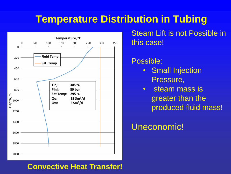
Transient Temperature Distribution by Enthalpy Balance

0

200

400

600

800

1000

1200

1400

1600

1800

2000

0 20 40 60 80 100

De

pth

, m

Temperature, oC

1 m3/d

5 m3/d

10 m3/d

15 m3/d

20 m3/d

25 m3/d

30 m3/d

35 m3/d

40 m3/d

45 m3/d

Pour Point

Production Time : 360 day

Temperature profile stabilized in short time!
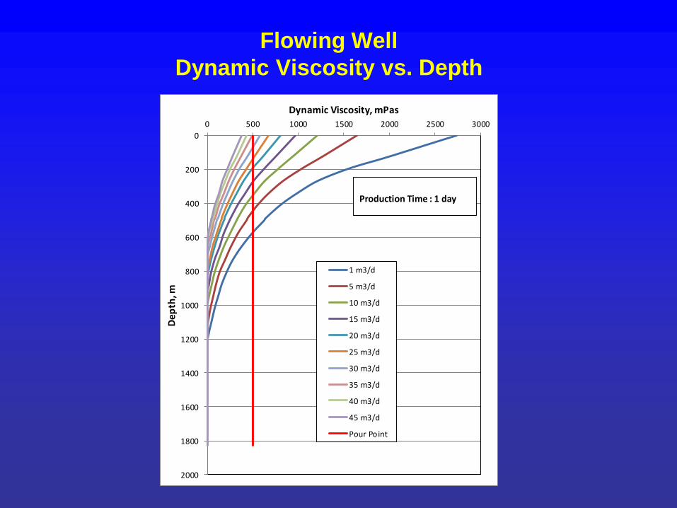
Flowing Well

Dynamic Viscosity vs. Depth

0

200

400

600

800

1000

1200

1400

1600

1800

2000

0 500 1000 1500 2000 2500 3000

De

pth

, m

Dynamic Viscosity, mPas

1 m3/d

5 m3/d

10 m3/d

15 m3/d

20 m3/d

25 m3/d

30 m3/d

35 m3/d

40 m3/d

45 m3/d

Pour Point

Production Time : 1 day

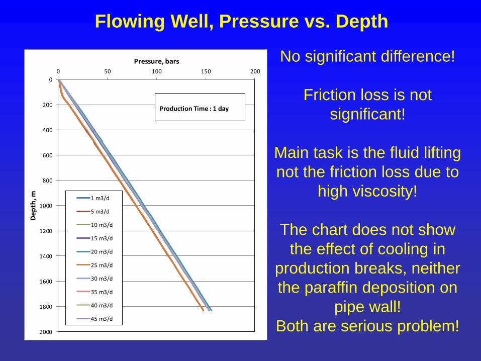
Flowing Well, Pressure vs. Depth

No significant difference!

Friction loss is not

significant!

Main task is the fluid lifting

not the friction loss due to

high viscosity!

The chart does not show

the effect of cooling in

production breaks, neither

the paraffin deposition on

pipe wall!

Both are serious problem!

0

200

400

600

800

1000

1200

1400

1600

1800

2000

0 50 100 150 200

De

pth

, m

Pressure, bars

1 m3/d

5 m3/d

10 m3/d

15 m3/d

20 m3/d

25 m3/d

30 m3/d

35 m3/d

40 m3/d

45 m3/d

Production Time : 1 day

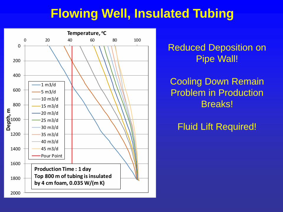
Flowing Well, Insulated Tubing

Reduced Deposition on

Pipe Wall!

Cooling Down Remain

Problem in Production

Breaks!

Fluid Lift Required!

0

200

400

600

800

1000

1200

1400

1600

1800

2000

0 20 40 60 80 100

De

pth

, m

Temperature, oC

1 m3/d

5 m3/d

10 m3/d

15 m3/d

20 m3/d

25 m3/d

30 m3/d

35 m3/d

40 m3/d

45 m3/d

Pour Point

Production Time : 1 dayTop 800 m of tubing is insulatedby 4 cm foam, 0.035 W/(m K)

Artificial Lift Required!

• Appropriate for Production Test– Cheap enough for single well

– Easy to install

– Flexible

– Applicable for highy pour point,

heawy oil

– Applicability after production test is

an Advantade

„Steam Lift”?

Required Minimal „gas lift pressure” - 30 bar ~ 220 oC

Examined 305 oC ~ 80 bar

100

150

200

250

300

350

0 20 40 60 80 100 120

Sa

tura

tio

n T

em

pe

ratu

re,

oC

Pressure, bar

Steam Saturation Temperature

Temperature vs. Depth of Steam

Injected into the Annulus

The cooling effect of tubing is neglected!

0

200

400

600

800

1000

1200

1400

1600

1800

2000

0 50 100 150 200 250 300 350

De

pth

, m

Temperature, oC

1 m3/d

2 m3/d

3 m3/d

4 m3/d

5 m3/d

6 m3/d

7 m3/d

8 m3/d

9 m3/d

10 m3/d

Sat. Temp.

Tinj: 305 oCPinj: 80 barSat Temp: 295 oC

Temperature vs. Depth of Steam

Injected into the Annulus

0

200

400

600

800

1000

1200

1400

1600

1800

2000

0 50 100 150 200 250 300 350

De

pth

, m

Temperature, oC

1 m3/d

2 m3/d

3 m3/d

4 m3/d

5 m3/d

6 m3/d

7 m3/d

8 m3/d

9 m3/d

10 m3/d

Sat. Temp.

Tinj: 305 oCPinj: 60 barSat Temp: 275.6 oC

The cooling effect of tubing is neglected!

Temperature Distribution in Tubing

Convective Heat Transfer!

Steam Lift is not Possible in

this case!

Possible:

• Small Injection

Pressure,

• steam mass is

greater than the

produced fluid mass!

Uneconomic!

0

200

400

600

800

1000

1200

1400

1600

1800

2000

0 50 100 150 200 250 300 350

De

pth

, m

Temperature, oC

Fluid Temp.

Sat. Temp

Tinj: 305 oCPinj: 80 barSat Temp: 295 oC

Qo: 15 Sm3/dQw: 5 Sm3/d

Dilutant Injection

To Decrease Viscosity and Pour Point

Constant Effect, Production Break Problems Eliminated

780

790

800

810

820

830

840

850

860

870

880

0

1000

2000

3000

4000

5000

6000

0 5 10 15

De

nsi

ty, k

g/m

3

Vis

cosi

ty, m

Pa

s

Dilutant Injection Rate, Sm3/d

Wellhead Liquid Viscosity

Wellhead Liquid Density

Dilutant Injection

To Decrease Viscosity and Pour Point

Constant Effect, Production Break Problems Eliminated

Must be combined by artificial lift!

0

2

4

6

8

10

12

14

0 2 4 6 8 10 12 14 16

Oil

Pro

du

ctio

n R

ate

, Sm

3/d

Dilutant Injection Rate, Sm3/d

Dilutant Injection

To Decrease Viscosity and Pour Point

Constant Effect, Production Break Problems Eliminated

0.0

0.2

0.4

0.6

0.8

1.0

1.2

1.4

0 20 40 60 80 100

Dyn

amic

Vis

cosi

ty, P

as

Temperature, oC

Effect of Diluting Agent on Oil Viscosity

0% 10%

20% 40%

50% 66%

Jet Pump

The diluting agent can be the power fluid

of the jet pump system.

Diluting agent can be:

heated water, revers flow application

heated well fluid, revers flow application

heated light oil, gasoline , lower temperature;

normal or revers flow application

Jet Pump

Using heated water and heated well fluids

small power fluid requirement, continuous

cleaning and recirculating

Using light oil, or gasoline

continuous power fluid supply is required

Possible power fluid choice could be water

with 5-10 % gasoline, bigger safety in case

of production breaks.

The surface units required for jet pumping

is slightly more complicated than in case of

simple diluting agent injection.

Jet Pump

No moving parts in the downhole pump,

long production life, low repair cost

If free-pump installation is used, the pump

can be circulated to the bottom, to produce,

or can be circulated to the surface for

repair. No need for high cost tubing

operations.

Jet Pump

Reverse flow installation Normal flow installation

Jet Pump

Normal flow installation Normal flow installation

Jet Pump

The best fluid ratio (Produced liquid rate/Power fluid rate):

30 Sm3/day power fluid rate

210 bars surface injection pressure.

Production rate < the required 30 m3/day.

Suggested:

185 bar power fluid surface injection pressure,

60 Sm3/day injection rate.

Conclusions

• In case of low rates the high viscosity does not

cause high friction loss

• Insulation decrease the problems due to

production breaks and deposition

• Fluid lifting is the main problem

• Steam Lift is not an economic solution

• Dilitant ijection Must be combined with artificial

lifting

• Jet Pump is a valuable tool for heavy oil

production

Thank You for Your Attention!


Recommended