55
Produto – Rev.1.1
Produto – Rev.1.1

MP-4000 TH Service Manual Code: 501.3421.00 - Rev.1.1 March 2008 August 2007 (First Edition) Copyright © Bematech S. A., São José dos Pinhais-PR, Brazil All rights reserved. No part of this publication may be copied, reproduced, adapted or translated without the prior written permission of Bematech S.A., except when allowed by patent rights. Information in this publication is purely informative, subjected to change without notice and no liability is assumed with respect to the use of this. However, as product improvements become available, Bematech S.A. will make every effort to provide updated information for the products described in this publication. The latest version of this manual can be obtained through Bematech website:
www.bematech.com Notwithstanding the other exceptions contained in this Manual, the consequences and responsibility are assumed by the Purchaser of this product or third parties as a result of: (a) intentional use for any improper, unintended or unauthorized applications of this product, including any particular purpose; (b) unauthorized modifications, repairs, or alterations to this product; (c) use of the product without complying with Bematech S.A. Corporation’s operating and maintenance instructions; (d) use of the product as component in systems or other applications in which the failure of this could create a situation where personal injury or material damages may occur. In the events described above, Bematech S.A. and its officers, administrators, employees, subsidiaries, affiliates and dealers shall not be held responsible or respond by any claim, costs, damages, losses, expenses and any other direct or indirect injury, as well as claims which alleges that Bematech S.A. was negligent regarding the design or manufacture of the product. Bematech S.A. shall not be liable against any damages or problems arising from the use of any options or any consumable products other than those designated as original Bematech products or approved products by Bematech S.A. Any product names or its logotypes mentioned in this publication may be trademarks of its respective owners and shall be here recognized. Product warranties are only the ones expressly mentioned in the User’s Manual. Bematech S.A. disclaims any and all implied warranties for the product, including but not limited to implied warranties of merchantability or fitness for a particular purpose. In addition, Bematech S.A. shall not be responsible or liable for any special, incidental or consequential damages or lost profits or savings arising from the use of the product by the Purchaser, the User or third parties.
Summary
Introduction...........................................................................................................5 Who should read this manual?..................................................................................5 How this manual is organized ...................................................................................5 Other related publications and software .....................................................................5 Where to find more information ................................................................................5
Chapter 1 ............................................................................................. 6 Product Description ................................................................................................. 6
Package contents....................................................................................................6 Chart of Models ......................................................................................................7 Product electronics .................................................................................................7
Control Board......................................................................................................7 Connectors.......................................................................................................8 Jumpers...........................................................................................................8 Blocks Diagram.................................................................................................9
Parallel Interface Board ...................................................................................... 10 Block Diagram ................................................................................................ 10 Female Centronics Connector (Printer) ............................................................... 11 Communication Cable ...................................................................................... 11
Serial Interface Board DB-9................................................................................. 12 Dip Switches .................................................................................................. 12 Block Diagram ................................................................................................ 13 Female DB-9 Connector (Printer)....................................................................... 13 Communication Cable ...................................................................................... 13
Serial Board DB-25 ............................................................................................ 14 Dip Switch ..................................................................................................... 14 Block Diagram ................................................................................................ 15 Female DB-25 Connector (Printer) ..................................................................... 15 Communication Cable ...................................................................................... 15
USB Interface Board........................................................................................... 16 Blocks Diagram............................................................................................... 16 Female Type B Connector (Printer) .................................................................... 16 Communication Cable ...................................................................................... 16
Ethernet Interface Board..................................................................................... 17 Block Diagram ................................................................................................ 17 Female RJ-45 Connector (Printer)...................................................................... 18 Communication Cable ...................................................................................... 18
AC Adapter ....................................................................................................... 18 Product exploded view (with part numbers).............................................................. 20
Product exploded view........................................................................................ 20 Exploded view of the Control Board Cartridge Set ................................................... 21 Exploded view of the Cabinet Set ......................................................................... 22 Exploded view of the Cover Lever Set ................................................................... 23 Exploded view of the Thermal Print Head Set ......................................................... 23 Exploded view of the Connection Board Set ........................................................... 24 Exploded view of the Cutter Mechanism Set........................................................... 25
Chapter 2 ........................................................................................... 26 Procedures ............................................................................................................ 26
Product disassembly and assembly procedures for module replacement........................ 26 Precautions before Disassembly and Assembly ....................................................... 26 Removing the Control Board Set .......................................................................... 26 Removing the Cutter Mechanism, Print Head and Connection Board .......................... 28 Removing the Cover Lever Set............................................................................. 34
Firmware update .................................................................................................. 35 User's Software ................................................................................................. 35 Technical Support Software. ................................................................................ 36
Product test procedures......................................................................................... 37 Technical Support Software ................................................................................. 37
Tab 'Configuration' .......................................................................................... 37 Tab 'Print' ...................................................................................................... 38 Tab 'Bitmap & Logo' ........................................................................................ 39 Tab 'Bar code'................................................................................................. 40 Tab 'Status'.................................................................................................... 41 Tab 'Additional Commands'............................................................................... 42 Tab 'Macro' .................................................................................................... 43 Tab 'Tests' ..................................................................................................... 44
Preventive Maintenance Procedures......................................................................... 45 Cleaning Procedures........................................................................................... 45
Print Head...................................................................................................... 45 Platen roller.................................................................................................... 45 Cutter ........................................................................................................... 45 Sensors ......................................................................................................... 45 Inner Case ..................................................................................................... 45 External Surfaces ............................................................................................ 45
Chapter 3 ........................................................................................... 46 Operation and Troubleshooting ............................................................................. 46
Indicative Lights................................................................................................... 46 Recoverable Error - Yellow Information LED........................................................... 46
Yellow LED On - Open Cover ............................................................................. 46 Yellow LED blinking 1 time - No Paper. ............................................................... 49 Yellow LED Blinking 2 times - Overheated Print Head............................................ 49 Yellow LED blinking 3 times - Cutter Error........................................................... 50 Yellow LED blinking 4 times - Communication Error.............................................. 50
Unrecoverable Error - Information LED in Red ........................................................ 50 Red LED blinking 1 time - RTOS (Real Time Operation System) Error...................... 50 Red LED blinking 3 times - RAM Memory Error..................................................... 51 Red LED blinking 8 times - Print Mechanism Error ................................................ 51 Red LED blinking 11 times - Low DC voltage sent by the power source.................... 51 Red LED blinking 12 times - Cutter Initialization Error .......................................... 51
Troubleshooting ................................................................................................... 52
Chapter 4 ........................................................................................... 53 Technical Specifications......................................................................................... 53

5
Introduction This manual provides information on the identification and troubleshooting, test procedures and a list of replacement parts for the MP-4000 TH printer. Who should read this manual? This manual is intended only for technicians trained by Bematech. How this manual is organized Chapter 1 Knowing the product. Description and operation of MP-4000 TH Printer. Chapter 2 Product maintenance and test procedures. Chapter 3 MP-4000 TH operation and troubleshooting. Chapter 4 MP-4000 TH technical specifications and features. Other related publications and software User’s Manual Programmer’s Manual Quick Start Guide User Software Technical Support Software Where to find more information English Content at http://www.bematech.com Spanish Content at http://www.bematech.com/es Portuguese Content at http://www.bematech.com.br

6
Chapter 1 Product Description
High performance, flexibility and ease of operation are some of the features that make the Bematech MP-4000 TH the ideal printing solution for your retail outlet, operating with high quality, high speed and reliability with reduced operation cost. Package contents Remove the MP-4000 TH printer from the package and make sure that all components listed below are available, and that they are in perfect shape:
MP-4000 TH Printer; Quick Reference Guide; Spacer; Thermal paper roll; Power supply; Power supply cable; Communication cable*.
* The communication and power cable provided will depend on the chosen configuration.
7
Chart of Models The MP-4000 TH Printer is available in the following configurations:
Model Features
101.2211.10 Black color with Serial communication board (DB-9)
101.2211.11 Black color with Serial communication board (DB-25)
101.2211.12 Black color with Parallel communication board
101.2211.13 Black color with USB communication board
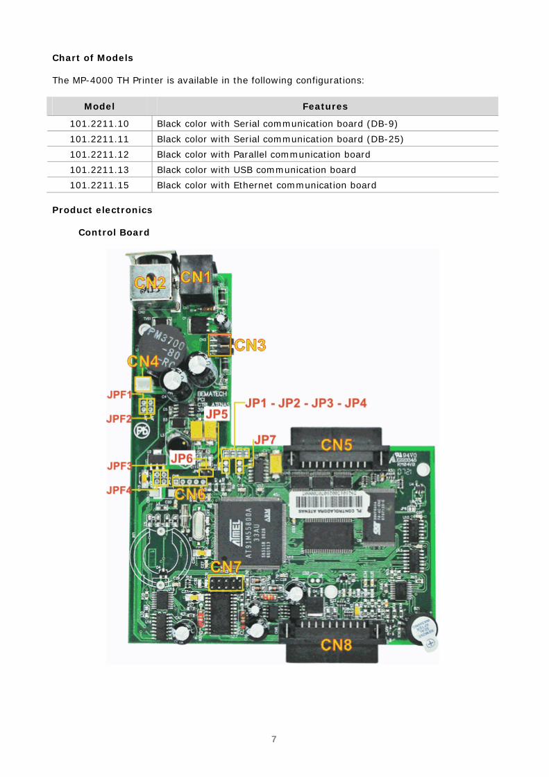
101.2211.15 Black color with Ethernet communication board Product electronics
Control Board
8
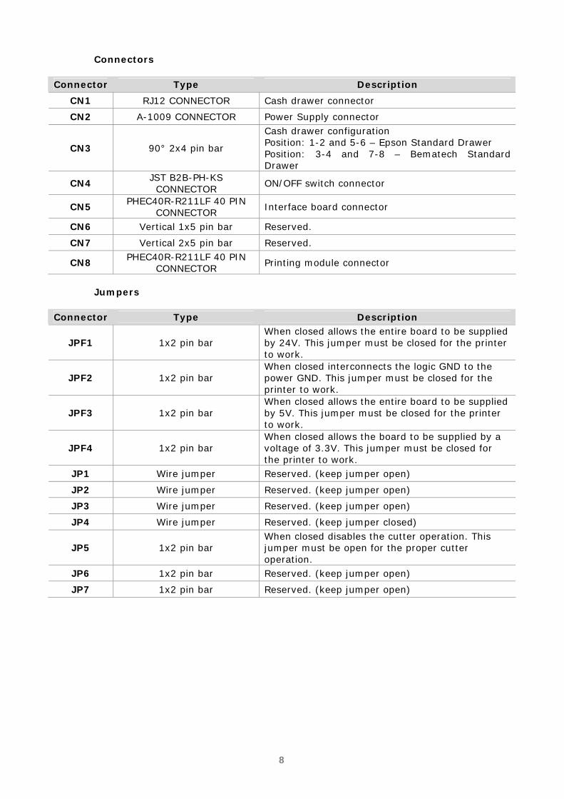
Connectors Connector Type Description
CN1 RJ12 CONNECTOR Cash drawer connector
CN2 A-1009 CONNECTOR Power Supply connector
CN3 90° 2x4 pin bar
Cash drawer configuration Position: 1-2 and 5-6 – Epson Standard Drawer Position: 3-4 and 7-8 – Bematech Standard Drawer
CN4 JST B2B-PH-KS CONNECTOR
ON/OFF switch connector
CN5 PHEC40R-R211LF 40 PIN
CONNECTOR Interface board connector
CN6 Vertical 1x5 pin bar Reserved.
CN7 Vertical 2x5 pin bar Reserved.
CN8 PHEC40R-R211LF 40 PIN
CONNECTOR Printing module connector
Jumpers
Connector Type Description
JPF1 1x2 pin bar When closed allows the entire board to be supplied by 24V. This jumper must be closed for the printer to work.
JPF2 1x2 pin bar When closed interconnects the logic GND to the power GND. This jumper must be closed for the printer to work.
JPF3 1x2 pin bar When closed allows the entire board to be supplied by 5V. This jumper must be closed for the printer to work.
JPF4 1x2 pin bar When closed allows the board to be supplied by a voltage of 3.3V. This jumper must be closed for the printer to work.
JP1 Wire jumper Reserved. (keep jumper open)
JP2 Wire jumper Reserved. (keep jumper open)
JP3 Wire jumper Reserved. (keep jumper open)
JP4 Wire jumper Reserved. (keep jumper closed)
JP5 1x2 pin bar When closed disables the cutter operation. This jumper must be open for the proper cutter operation.
JP6 1x2 pin bar Reserved. (keep jumper open)
JP7 1x2 pin bar Reserved. (keep jumper open)

9
Blocks Diagram
CPUAT91M55800A
MECHANISM DRIVER ICCUTTER DRIVER IC
STEP MOTOR
THERMAL HEAD
DC MOTOR
SENSOR
DRAWER DRIVER IC
BUZZER
RESET
SRAM(DATA MEMORY)
FLASH(FIRMWARE)
D0-D15
A1-A19
A1-A19
D0-D15
COMMUNICATION INTERFACE
(ETHERNET, USB, SERIAL, PARALEL,
WI-FI)
KEY PANELLEDS
SENSORS

10
Parallel Interface Board The IC U2, ATMEGA16 (microcontroller), is responsible for the communication between the printer and the computer. The IC U3, 74LVC/LCX125 is a buffer and also functions as a level adapter, making the voltage conversion in some signals (5V to 3.3V). The recognition of the interface connected to the control board is done with the reading of a code associated to each kind of board through U1, enabled by the SELDEV signal generated by the control board. In this interface there are still two CN2 connectors (5x2 pin bar), which are used to the programming of the microcontroller and CN3 (5x2 pin bar), reserved.
Block Diagram
ATMEGA16 CONTROL BOARDCENTRONICSCONNECTOR
(36 PINS)
FCI CONNETOR (40 PINS)
INTERFACE IDENTIFIER
ISP
RESET
HOST

11
Female Centronics Connector (Printer)
Pin Signal 1 nStrobe 2 Data 0 3 Data 1 4 Data 2 5 Data 3 6 Data 4 7 Data 5 8 Data 6 9 Data 7 10 nAck 11 Busy 12 Paper-Out/Paper End 13 Select 14 nAuto-Linefeed 31 nInitialize 32 nError / nFault
36 nSelect-Printer
nSelect-In 19-30 Ground
Communication Cable
Mal
eC
entro
nics
Con
nect
or(3
6 pi
n) Male
DB
-25C
onnector
123456789
101112131432313633
19, 2021, 2223, 2425, 26
2728, 2916, 30
12345678910111213141516171819202122232425
MaleCentronics 36
MaleDB-25

12
Serial Interface Board DB-9 IC U2 (MAX3232) converts the levels originated into the microcontroller serial interface, which are of 3.3V to signals of ±10V, compatible with RS232 standard and the RS232 signals originated from the outside in 3.3V signals compatible with the microcontroller. The available signals on the interface are RXD, TXD, RTS and CTS. The recognition of the interface connected to the control board is done with the reading of a code associated to each kind of board through U1, enabled by the SELDEV signal generated by the control board. Pin 1, with voltage of +5V and a 500mA current, supplies peripheral equipments connected to the serial port. On the S1 dip-switch, it is possible to adjust the serial communication configurations (stop bits, parity, etc.). Below, there are some charts that contain the functions of each set of switches. The configurations in Underlined-Bold face are the factory defaults.
Dip Switches
1 2 3 4 5 6 7 8
ON DIP
1 2 3 4 5 6 7 8
ON DIP
1 2 3 4 5 6 7 8
ON DIP
1 2 3 4 5 6 7 8
ON DIP
1 2 3 4 5 6 7 8
ON DIP
1 2 3 4 5 6 7 8
ON DIP
1 2 3 4 5 6 7 8
ON DIP
1 2 3 4 5 6 7 8
ON DIP
1 2 3 4 5 6 7 8
ON DIP
1 2 3 4 5 6 7 8
ON DIP
1 2 3 4 5 6 7 8
ON DIP
1 2 3 4 5 6 7 8
ON DIP
1 2 3 4 5 6 7 8
ON DIP
1 2 3 4 5 6 7 8
ON DIP
1 2 3 4 5 6 7 8
ON DIP
1 2 3 4 5 6 7 8
ON DIP
1 2 3 4 5 6 7 8
ON DIP
1 2 3 4 5 6 7 8
ON DIP
1 2 3 4 5 6 7 8
ON DIP
1200
DIP SWITCH BAUD RATE
DIP SWITCH DIP SWITCH HANDSHAKINGSTOP BITS
DIP SWITCH
DIP SWITCH LENGTH
PARITY
DEFAULT
2400
4800
9600
19200
38400
115200
230400
1 STOP BIT
NONE
ODD
EVEN
8 BITS
7 BITS
NONE
RTS/CTS
XON/XOFF2 STOP BIT

13
Block Diagram
MAX3232 CONTROL BOARDFEMALE DB-9 CONNECTOR
FCI CONNECTOR
(40 PINS)
INTERFACE IDENTIFIER
MICROTERMINAL / HOST
SERIAL COMMUNICATION CONFIGURATION
Female DB-9 Connector (Printer)
5 4 3 2 1
9 8 7 6
Pin Signal 1 +5V 2 RXD 3 TXD 4 NC 5 GND 6 NC 7 RTS 8 CTS 9 NC
Communication Cable
32587146
23578146
MaleDB-9
FemaleDB-9
CN A CN B

14
Serial Board DB-25 The ICs U2 and U3 (MAX3232) convert the levels originated from the microcontroller serial interface, which are of 3,3V into signals of ±10V, compatible with RS232 standard and the RS232 signals originated from the outside in 3,3V signals compatible with the microcontroller. The available signs on the interface are RXD, TXD, RTS, CTS, DTR and DSR. The recognition of the interface connected to the control board is made by the reading of a code associated to each kind of board through the U6 enabled by the SELDEV signal generated by the control board. Jumpers JP2 and JP3, when closed, supply peripheral connected to the serial port with voltage of +5V and 500mA current (must be closed only when needed). On the S1 dip-switch, it is possible to adjust the serial communication configurations (stop bits, parity, etc.). Below, there are some charts that contain the functions of each set of switches. The configurations in Underlined-Bold face are the factory default.
Dip Switch
1 2 3 4 5 6 7 8
ON DIP
1 2 3 4 5 6 7 8
ON DIP
1 2 3 4 5 6 7 8
ON DIP
1 2 3 4 5 6 7 8
ON DIP
1 2 3 4 5 6 7 8
ON DIP
1 2 3 4 5 6 7 8
ON DIP
1 2 3 4 5 6 7 8
ON DIP
1 2 3 4 5 6 7 8
ON DIP
1 2 3 4 5 6 7 8
ON DIP
1 2 3 4 5 6 7 8
ON DIP
1 2 3 4 5 6 7 8
ON DIP
1 2 3 4 5 6 7 8
ON DIP
1 2 3 4 5 6 7 8
ON DIP
1 2 3 4 5 6 7 8
ON DIP
1 2 3 4 5 6 7 8
ON DIP
1 2 3 4 5 6 7 8
ON DIP
1 2 3 4 5 6 7 8
ON DIP
1 2 3 4 5 6 7 8
ON DIP
1 2 3 4 5 6 7 8
ON DIP
1200
DIP SWITCH BAUD RATE
DIP SWITCH DIP SWITCH HANDSHAKINGSTOP BITS
DIP SWITCH
DIP SWITCH LENGTH
PARITY
DEFAULT
2400
4800
9600
19200
38400
115200
230400
1 STOP BIT
NONE
ODD
EVEN
8 BITS
7 BITS
NONE
DTR/DSR
XON/XOFF2 STOP BIT

15
Block Diagram
CONTROL BOARDFEMALE DB-25 CONNECTOR
FCI CONNECTOR
(40 PINS)
INTERFACE IDENTIFIER
MICROTERMINAL / HOST
SERIAL COMMUNICATION CONFIGURATION
MAX3232
MAX3232
Female DB-25 Connector (Printer)
25 24 23 22 21 20 19 18 17 16 15 14
13 12 11 10 9 8 7 6 5 4 3 2 1
Pin Signal 1 GND 2 TXD 3 RXD 4 RTS 5 CTS 6 DSR 7 GND 8 +5V 20 DTR 22 +5V 25 INIT
Communication Cable
14 15 16 17 18 19 20 21 22 23 24 25
1 2 3 4 5 6 7 8 9 10 11 12 13 CN B
DB-9F
CN A
DB-25M
CLA
MP C
LAM
P
5 4 3 2 1
9 8 7 6
236820574
23416758
MaleDB-25
FemaleDB-9
CN A CN B

16
USB Interface Board The IC U1, CP2102, is the IC responsible for the conversion of CMOS RS-232 signals originated from the control board microcontroller for compatible signals with the USB interface, as well as the conversion of USB signals originated from the outside into CMOS RS-232 signals. The recognition of the interface connected to the control board is done with the reading of a code associated to each kind of board through U2, enabled by the SELDEV signal generated by the control board.
Blocks Diagram
PC2102USB
CONNECTOR (TYPE B)
MICROTERMINAL / HOST
FCI CONNECTOR
(40 PINS)CONTROL BOARD
INTERFACE IDENTIFIER
Female Type B Connector (Printer)
Pin Signal 1 VBUS 2 D - 3 D+ 4 GND
Communication Cable
MaleType A
MaleType B
1 2
34
4 3 2 1 1234
1234
MaleType A
MaleType B

17
Ethernet Interface Board The IC U4, 89C51 (microcontroller), performs the serial communication with the control board and organizes these signals so they are compatible with the TCP/IP protocol and relay data to IC U6 (W3100), which provides the TCP/IP stacks. The integrated circuit U3 (RTL8201B) performs the functions of the Ethernet 10/100Mbps communication standard with the physical device. In the EEPROM (U1) are stored the MAC and IP addresses of the network adapter. The recognition of the interface connected to the control board is made with the reading of a code associated to each kind of board through U101, enabled by the SELDEV signal generated by the control board. There are configuration jumpers: JP1 enables the manual reset of PCB, for test purposes (this jumper must be open for the printer to work); J1, when closed, allows the IC U4 firmware update (this jumper must be open for the proper operation of the printer). J3 jumper is reserved and must be open for the printer to work properly.
Block Diagram
AT89C51RC2
CONTROL BOARD
RJ11 CONNECTOR
FCI CONNECTOR (40 PINS)
INTERFACEIDENTIFIER
IP/MACADDRESS
ETHERNET
W3100RTL8201B
RESET
SRAM

18
Female RJ-45 Connector (Printer)
Pin Signal 1 TD+ 2 TD- 3 RD+ 4 TCT 5 RCT 6 RD- 7 NC 8 GND
Communication Cable
12345678
12345678
MaleRJ-45
MaleRJ-45
AC Adapter Basic Features • Universal Input Voltage 90 to 264VAC • Power Saving < 0.75W (no load standby) • Consumption: 60W • Output Voltage: 24V • Output Current: 2.5A (typical) • High Efficiency 80% typical • High Reliability • Low Ripple & Noise • Short Circuit Protection • Overvoltage Protection • Limited Power Source Environmental • Operating Temperature: 0 ~ +40C • Operating Humidity: 20 ~ 85% • Storage Temperature: - 40 ~ +70C • Storage Humidity: 10 ~ 95% • Hi-Pot: 1500 VAC 1Sec. (P. to S.) for Class I 3000 VAC 1Sec. (P. to S.) for Class II • MTBF > 50.000Hrs at 25 C Dimensions • L110*W62.2*H32mm

19
Connector • Connector type: 3 pins
Connector Specification A 24VDC B GND C N.C
Certifications Approved Standards: UL60950, EN60950, UL6500, EN60065.

20
Product exploded view (with part numbers)
ATTENTION!
The following part numbers are not necessarily available as stand alone units, as they are part of a replacement kit. For further information, refer to the Support section of our website www.bematech.com
Product exploded view
21
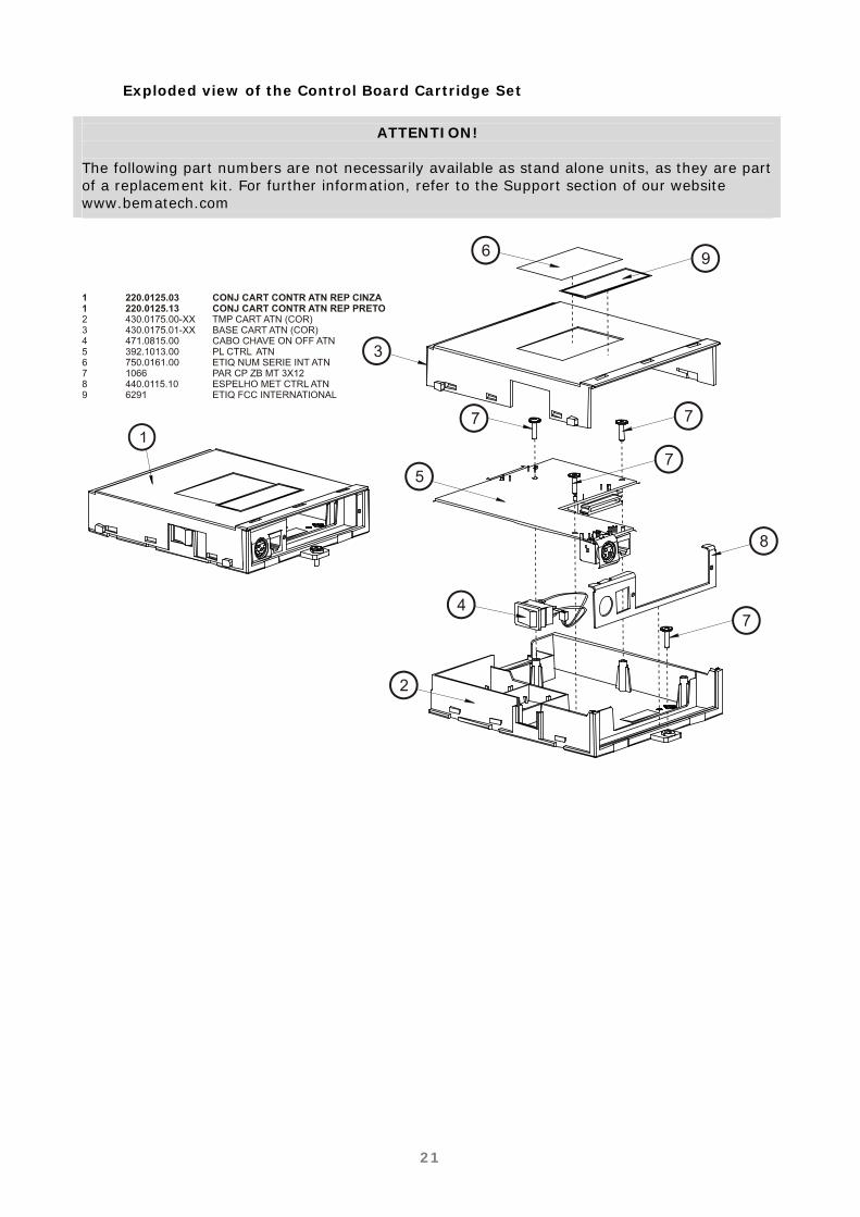
Exploded view of the Control Board Cartridge Set
ATTENTION!
The following part numbers are not necessarily available as stand alone units, as they are part of a replacement kit. For further information, refer to the Support section of our website www.bematech.com

22
Exploded view of the Cabinet Set
ATTENTION!
The following part numbers are not necessarily available as stand alone units, as they are part of a replacement kit. For further information, refer to the Support section of our website www.bematech.com
23
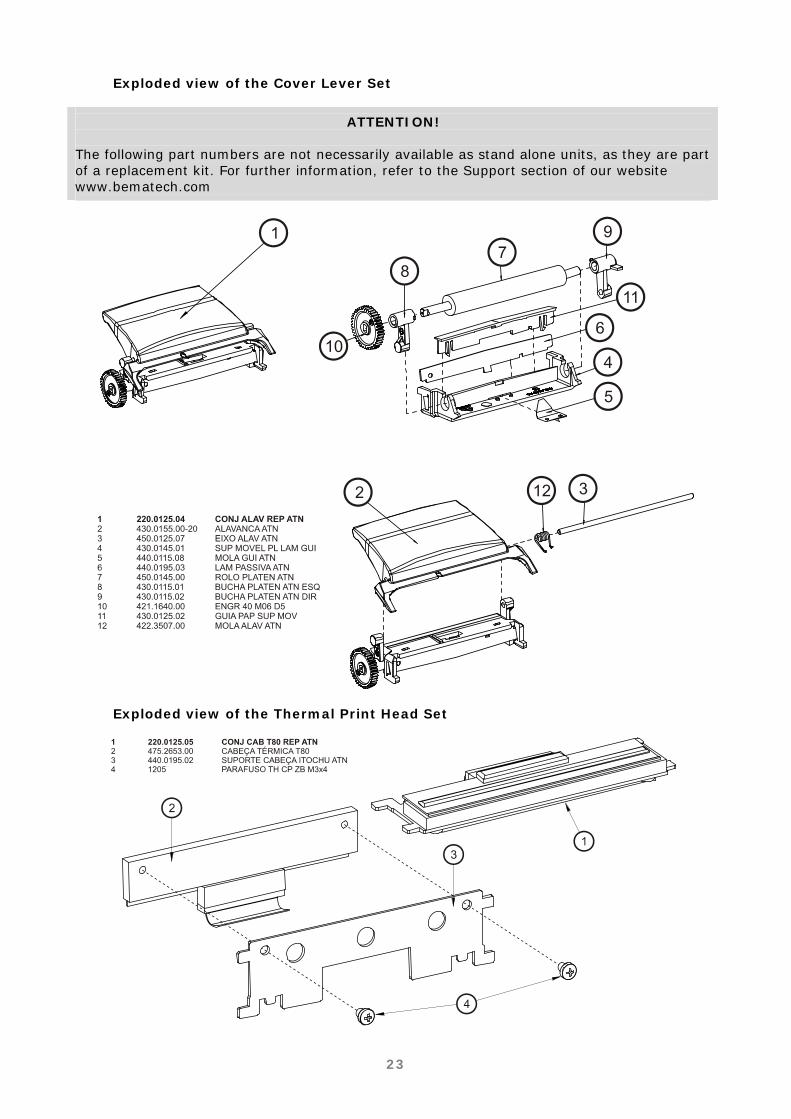
Exploded view of the Cover Lever Set
ATTENTION!
The following part numbers are not necessarily available as stand alone units, as they are part of a replacement kit. For further information, refer to the Support section of our website www.bematech.com
Exploded view of the Thermal Print Head Set

24
Exploded view of the Connection Board Set
ATTENTION!
The following part numbers are not necessarily available as stand alone units, as they are part of a replacement kit. For further information, refer to the Support section of our website www.bematech.com
25
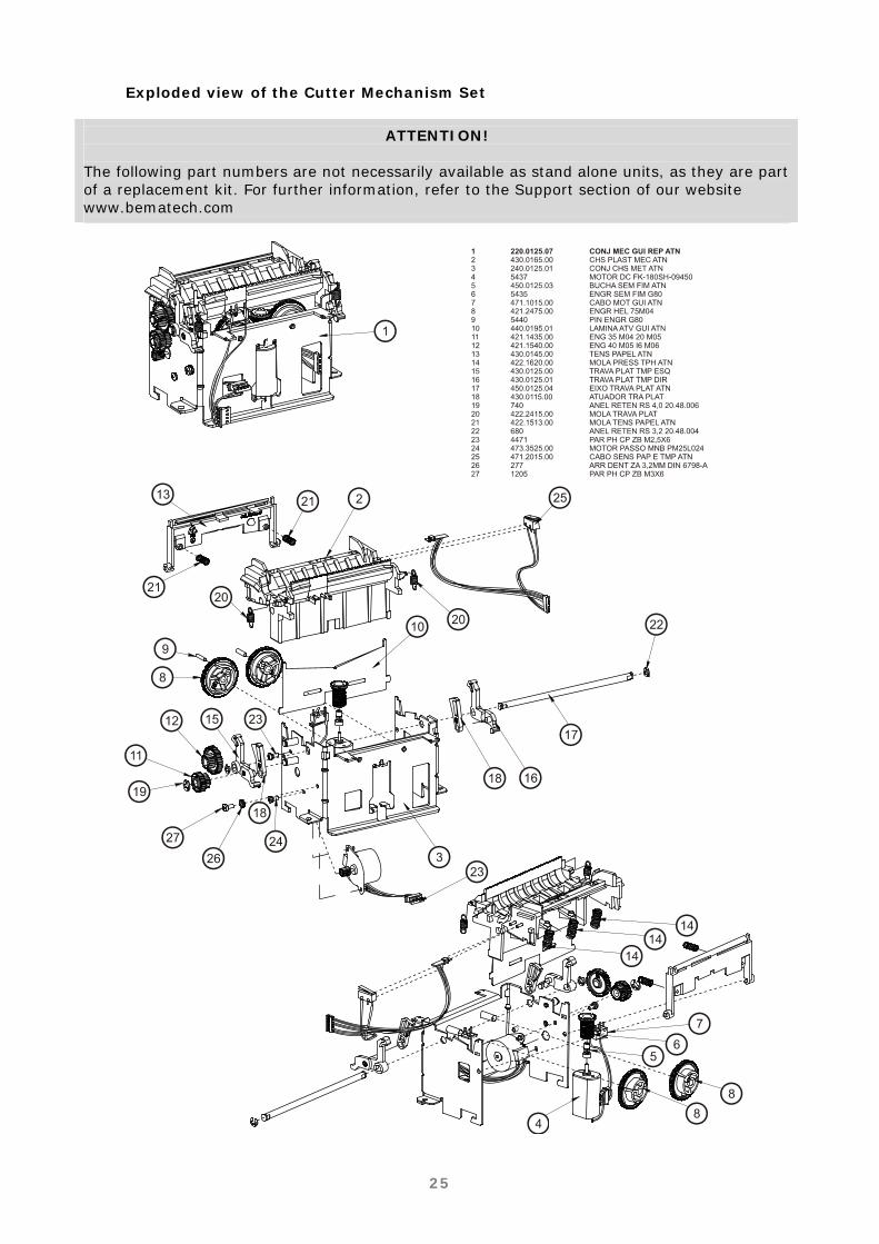
Exploded view of the Cutter Mechanism Set
ATTENTION!
The following part numbers are not necessarily available as stand alone units, as they are part of a replacement kit. For further information, refer to the Support section of our website www.bematech.com

26
Chapter 2 Procedures Product disassembly and assembly procedures for module replacement
Precautions before Disassembly and Assembly 1. Try to avoid disassembly, assembly and unnecessary adjustments on the MP-4000 TH parts that are working properly; 2. Before turning on the MP-4000 TH, make sure that all cables are properly connected; 3. During the maintenance procedure, do not let loose screws and other components inside the printer; 4. When handling printed circuit boards, do not use gloves that can generate static electricity. Use an anti-static wrist-strap connected to an anti-static mat or to a grounding system adequate for that purpose; 5. Do not place the printed circuit board over conductive surfaces. Use an anti-static bag or an anti-static mat connected to a grounding system adequate to that purpose; 6. When assembling or disassembling the MP-4000 TH, verify the cables for visible damage and reconnect them in normal position, noting the proper polarization. 7. The steps below will show how to disassemble the product; the reassembly is done in the same way, but backwards.
Removing the Control Board Set
To remove the control board set, remove the screw that holds it to the printer. The screw is illustrated in the picture.
27
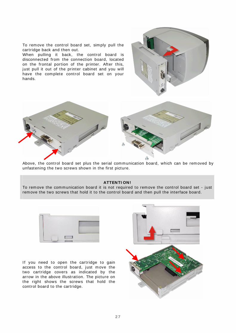
To remove the control board set, simply pull the cartridge back and then out. When pulling it back, the control board is disconnected from the connection board, located on the frontal portion of the printer. After this, just pull it out of the printer cabinet and you will have the complete control board set on your hands.
Above, the control board set plus the serial communication board, which can be removed by unfastening the two screws shown in the first picture.
ATTENTION!
To remove the communication board it is not required to remove the control board set - just remove the two screws that hold it to the control board and then pull the interface board.
If you need to open the cartridge to gain access to the control board, just move the two cartridge covers as indicated by the arrow in the above illustration. The picture on the right shows the screws that hold the control board to the cartridge.

28
Removing the Cutter Mechanism, Print Head and Connection Board
To access the printer interior, the cutter mechanism, thermal print head and connection board, follow the steps below: Begin disassembly by removing the control board cartridge, according to the previous topic. With the printer open, paper roll and spacer removed, loosen the two screws on the inside of the Printer, as shown on the right.
To separate the body from the base, first lift the back part of the body case, and then pull the front. There is a lock on the front which will only be released when the back is lifted.

29
After the body case is disconnected from the base, lift the frontal part first. You will see that the low paper sensor cable is connected to the connection board. Disconnect this cable very carefully so it doesn't get damaged. When reassembling the equipment, make sure that you connect the cable on the inside of the body case as shown by the arrows (figure below, on the left); pass the cable by the right side of the cutter mechanism, so that when the body case is remounted it doesn't squeeze the cable, damaging it.
To remove the cutter mechanism and the connection board, first remove the control board cartridge then loosen the screws on the cutter mechanism side - the ones pointed by the yellow arrows in the picture - and push the mechanism back alongside the connection board, as pointed by the red arrows. The mechanism is released and can be lifted to be separated from the base. The Cutter Mechanism and Connection Board will be removed from the MP-4000 TH base. On the back side of the mechanism, there is a tab that keeps it attached to the base, as shown on the pictures below.
30
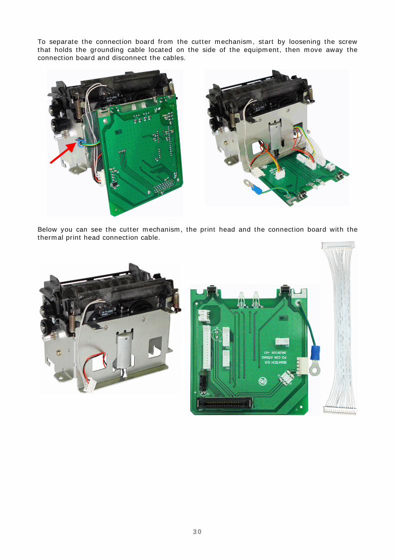
To separate the connection board from the cutter mechanism, start by loosening the screw that holds the grounding cable located on the side of the equipment, then move away the connection board and disconnect the cables.
Below you can see the cutter mechanism, the print head and the connection board with the thermal print head connection cable.
31
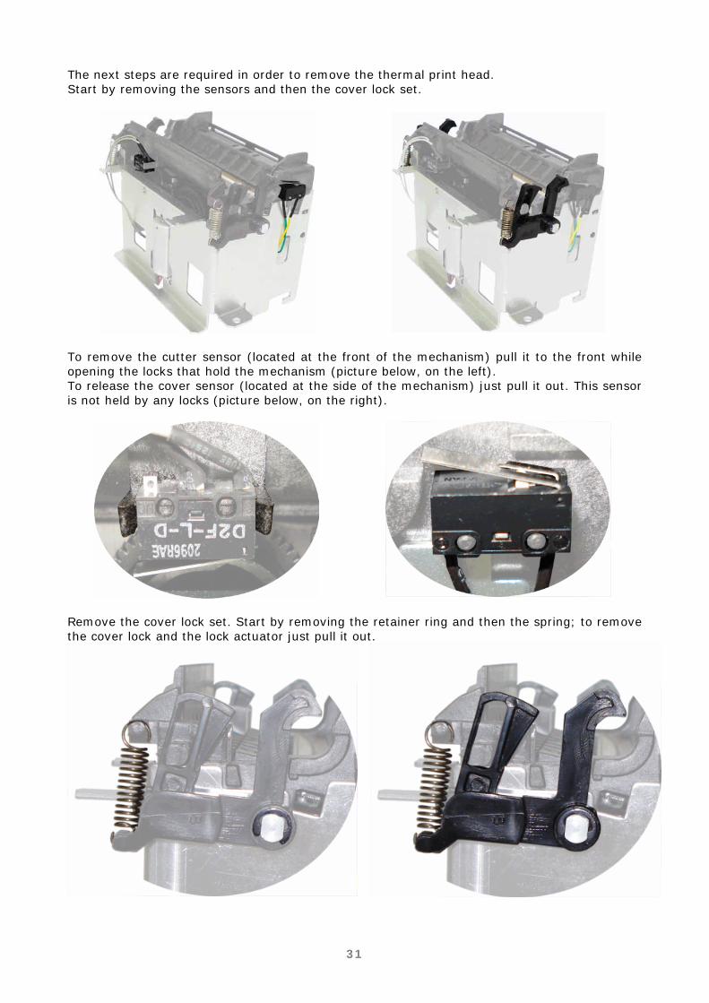
The next steps are required in order to remove the thermal print head. Start by removing the sensors and then the cover lock set.
To remove the cutter sensor (located at the front of the mechanism) pull it to the front while opening the locks that hold the mechanism (picture below, on the left). To release the cover sensor (located at the side of the mechanism) just pull it out. This sensor is not held by any locks (picture below, on the right).
Remove the cover lock set. Start by removing the retainer ring and then the spring; to remove the cover lock and the lock actuator just pull it out.
32
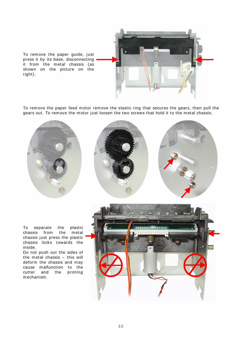
To remove the paper guide, just press it by its base, disconnecting it from the metal chassis (as shown on the picture on the right).
To remove the paper feed motor remove the elastic ring that secures the gears, then pull the gears out. To remove the motor just loosen the two screws that hold it to the metal chassis.
To separate the plastic chassis from the metal chassis just press the plastic chassis locks towards the inside. Do not push out the sides of the metal chassis – this will deform the chassis and may cause malfunction to the cutter and the printing mechanism.

33
After disconnecting the plastic chassis, just pull up the back side to loosen the frontal part. Only by separating the two chassis it is possible to have access to the thermal print head.
When the chassis assemble is performed, leave the gears and its pins on the same position, both with the pins pointing out (pictures below). That's required to ease the cutter blade fitting. Verify the proper position of the pins by inserting an Active blade, noticing the tangency through the blade oblong cuts in relation to the metallic chassis axle (pictures below). Use black BR12 grease to lubricate the helicoidal gear pins.
Misaligned Blade
Aligned Blade
To remove the thermal print head, just disconnect the three springs that hold it to the plastic chassis.

34
Removing the Cover Lever Set
To remove the lever set it is recommended that the printer cover is also removed. To remove the printer cover just pull the axle that holds the body case to one side (as shown in the picture on the right).
To remove the opening Lever Set, just press it from top to bottom on the points indicated on the picture.
The lever set will be completely removed. There is no need to disassemble any parts to remove it from the cover.

35
Firmware update
ATTENTION!
The product firmware update will only be possible through the serial DB9/DB25 or Ethernet interfaces. The product firmware update can be performed by using the 'User's Software' or the 'Technical Support Software'.
User's Software
On the tab 'Configuration' select the communication interface (serial DB9/DB25 or Ethernet) and click on apply.
Click on the button 'Load', on the field 'Update firmware'. On the window that was open, select the firmware that will be loaded and click on open. Click on the button 'update' and wait for the operation end. During the firmware update the printer LEDs keep on blinking in orange, indicating this function. The printer will be ready for use without the need to be turned off. In case two LEDs keep on blinking on the printer it is necessary to once more load the firmware which can be done through the same procedure.
36
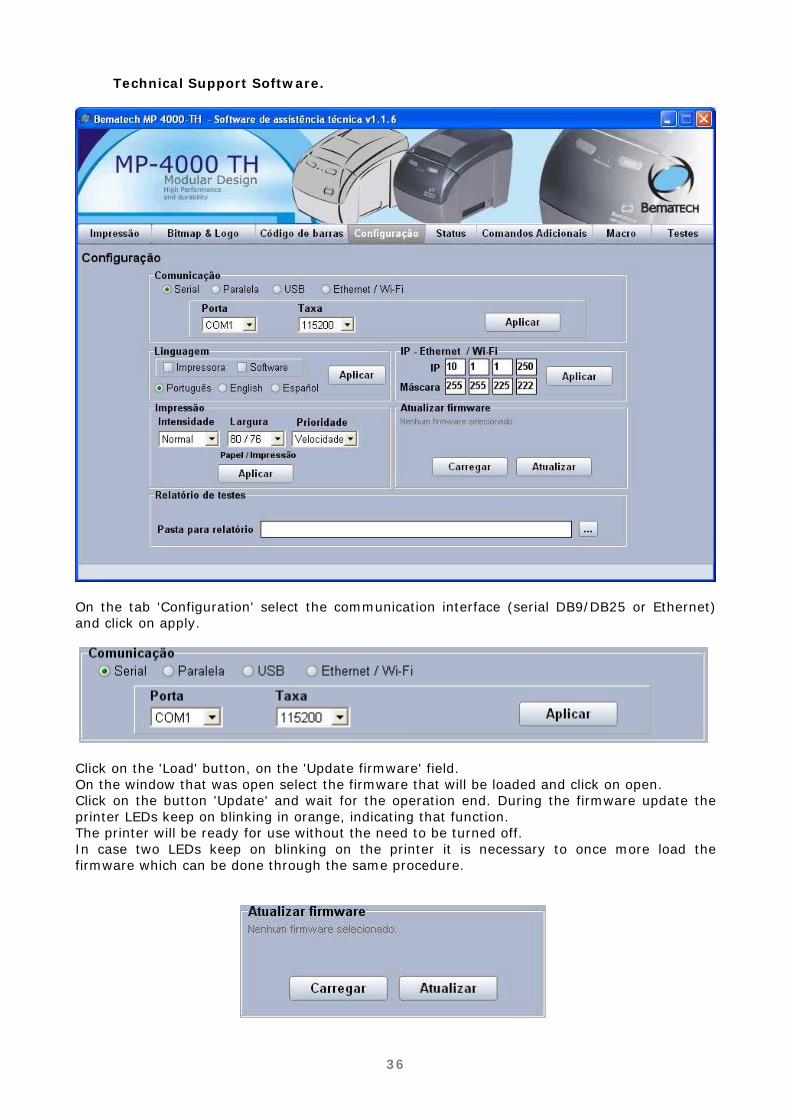
Technical Support Software.
On the tab 'Configuration' select the communication interface (serial DB9/DB25 or Ethernet) and click on apply.
Click on the 'Load' button, on the 'Update firmware' field. On the window that was open select the firmware that will be loaded and click on open. Click on the button 'Update' and wait for the operation end. During the firmware update the printer LEDs keep on blinking in orange, indicating that function. The printer will be ready for use without the need to be turned off. In case two LEDs keep on blinking on the printer it is necessary to once more load the firmware which can be done through the same procedure.
37
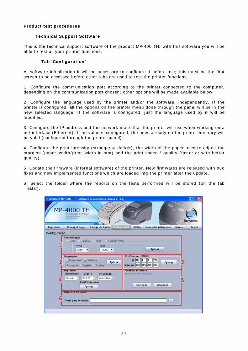
Product test procedures
Technical Support Software This is the technical support software of the product MP-400 TH; with this software you will be able to test all your printer functions.
Tab 'Configuration' At software initialization it will be necessary to configure it before use; this must be the first screen to be accessed before other tabs are used to test the printer functions. 1. Configure the communication port according to the printer connected to the computer, depending on the communication port chosen; other options will be made available below. 2. Configure the language used by the printer and/or the software, independently. If the printer is configured, all the options on the printer menu done through the panel will be in the new selected language. If the software is configured, just the language used by it will be modified. 3. Configure the IP address and the network mask that the printer will use when working on a net interface (Ethernet). If no value is configured, the ones already on the printer memory will be valid (configured through the printer panel). 4. Configure the print intensity (stronger = darker), the width of the paper used to adjust the margins (paper_width/print_width in mm) and the print speed / quality (faster or with better quality). 5. Update the firmware (internal software) of the printer. New firmwares are released with bug fixes and new implemented functions which are loaded into the printer after the update. 6. Select the folder where the reports on the tests performed will be stored (on the tab 'Tests').
38
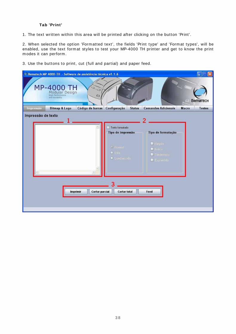
Tab 'Print' 1. The text written within this area will be printed after clicking on the button 'Print'. 2. When selected the option 'Formatted text', the fields 'Print type' and 'Format types', will be enabled, use the text format styles to test your MP-4000 TH printer and get to know the print modes it can perform. 3. Use the buttons to print, cut (full and partial) and paper feed.

39
Tab 'Bitmap & Logo'
ATTENTION!
Be careful with the images originally preloaded into the memories (volatile and non volatile) as they are used by the clients. Make sure you have them (or the client has them) before performing these tests.
1. In this field it is possible to choose an image to be printed in the MP-4000 TH. The option Bitmap allows you to check the graphics printing and the Logo option allows you to test the functions of logo storage and logo printing from volatile and non volatile memories. 2. When selected the option 'Enable transformation', it will be possible to make some changes in the image loaded for print, such as redimension, rotation and print type for the Bitmap. These functions do not apply to the Bitmaps (logos) stored in the memory. 3. As in the tab 'Print', here you can find the buttons to initiate printing, cutting (partial and fiull) and paper feeding.

40
Tab 'Bar code' 1. Choose the kind of bar code and type on the field 'Code' the value to be printed by the MP-4000 TH. 2. On this field it is possible to make some changes in the bar code that will be printed. You can choose between 'Width', 'Character position' and 'Font style' of the bar code.

41
Tab 'Status' 1. Click on the button 'Activate' to see the printer status. 2. Click on the button 'Get log' to get a complete report on the printer configuration.

42
Tab 'Additional Commands' 1. Test the printer buzzer. You can change the time the buzzer will be on and the time it will be off. You can also select how many times you want it to be activated by typing the quantity on the field 'Beeps'. The minimum and maximum beep values go from 0 to 63, and the time the buzzer will be on or off can vary from 100 to 9999. 2. Interface test for the connection of the cash drawer. Selecting the option 'Activate' you will get the current status of the drawer, 'Drawer open' or 'Drawer closed'. To open the drawer you just need to click on the button 'Open' and the printer will then give the command to open the drawer. 3. Choose what type of command you want to use by checking one of the two options available ('ESC/Bema' or ESC/POS®) and click on the button 'Apply' to configure the printer in the selected option. 4. Command to activate/deactivate the buttons on the front panel of the printer. Choose one of the options available 'Enable' or 'Disable' and click on the button 'Apply' to configure the printer in the selected option.
5. Command to activate/deactivate the paper near end sensor. Choose one of the options available 'Enable' or 'Disable' and click on the button 'Apply' to configure the printer in the option selected.
6. To check the configuration of the printer use this field and click on the button 'Print' to have them printed.
7. Adjusts the cutter activation time. The longer the time, the smaller the partial cut will be (it may cause just total cuts). The factory default value is 10.

43
Tab 'Macro' The tab 'Macro' allows tests to be processed in batch mode. 1. Configure the tests to be performed. The dialogue box 'Text print' allows selecting the formatting and origin of the text (file or keyboard) and how many times the print will be repeated. The dialogue box 'Bitmap print' allows testing the print of graphs from a BMP file. The logo print allows testing the Bitmap prints stored in the non volatile memory. The dialogue box 'Bar code' allows testing the bar code printing. The dialogue box 'Cuts' allows testing / repeated testing of partial and total cuts. The option 'Buzzer' allows testing of buzzer activation and the option 'Feed' allows to test the paper feeding. 2. To configure the printer parameters (language, intensity, width, priority, IP address and logo to be stored in non volatile memory).

44
Tab 'Tests' 1. For text and graphic printing select the modes you want to print and click on the button 'Print'. Do some tests for you to get familiar with the modes available. 2. Click on the button 'READ' to perform the MP-4000 TH printer sensor reading. The values shown correspond to the sensor levels. The printer interprets the value as follows: Paper sensor: there is still paper if the sensor value is over 30. Temperature sensor: is the temperature read in Celsius. Low paper sensor: there is still paper if the sensor value is over 80. Open cover sensor: the cover is closed if the sensor value is over 110. 3. MP-4000 TH printer test phases. Click on the button 'Start' to make a complete test of the printer. Execute the steps as required on the screen. By the end you will have performed a full printer checkup.

45
Preventive Maintenance Procedures
Cleaning Procedures
Print Head
ATTENTION! The print head might be hot after printing. Let it cool down before cleaning it. The thermal elements of the print head are fragile – do not touch them with any sharp objects or any abrasive material.
During regular operation some particles from the thermal paper may adhere to the thermal print head surface. It is recommended that the print head is cleaned every 10 km of printed paper or if the print quality has degraded. Turn off the printer before cleaning it. Clean the print head with a cotton swab soaked in isopropyl alcohol. Do not try to clean the print head with sharp objects, abrasives or using your fingers as this may damage the head surface.
Platen roller Clean the platen roller (rubber roller) with a cotton swab. Remove any dust particles from it. Never use chemically treated moistened cloths or any kind of chemical substance. The use of these products may cause the rubber in the roller to get dry, resulting in paper traction problems.
Cutter Clean the area near the cutter periodically. Use a soft bristle brush removing all paper dust residues which can accumulate in the cutter mechanism, causing malfunction.
Sensors Clean the MP-4000 TH sensors using a soft bristle brush. Remove all the dirt accumulated on the lens.
Inner Case Make sure the printer is off, open the cover and remove the paper roll. Use a flannel, a soft cloth or a soft bristle brush and carefully remove all the dust accumulated.
External Surfaces Clean the external cabinet with a soft cloth, moistened in water or neutral detergent. Never use a tow chemically treated or chemical substances like alcohol or similar solvent. The use of these products can make the cabinet of the printer changes its color or be deformed.

46
Chapter 3 Operation and Troubleshooting Indicative Lights The MP-4000 TH printer will flash indicative messages through the Information LED (i). The information may vary from the printer ready status to critical error warnings, which can lead to module replacement to correct a specific issue. On the chart below, you can see the messages given by the printer and the ways to correct the most common errors that may occur.
Colors LED
Status Light Signs Meaning - Procedure
On Ready to Print Green = OK
Blinking Ready to Print, but low on paper.
On Open Cover - Close the Cover
Blinking 1 time No Paper - Insert a new paper roll
Blinking 2 times Overheated Print Head - Wait to Print
Blinking 3 times
Cutter Error - Open the cutter to remove jammed paper (ERS)
Yellow Recoverable error
Blinking 4 times
Communication Error / Command Disregarded - Check Programming Mode
Blinking 1 time RTOS Error
Blinking 3 times RAM Memory Error
Blinking 8 times Print Mechanism Error
Blinking 11 times Low DC tension sent by the power source
Red Unrecoverable
Error
Blinking 12 times Cutter Initialization Error
Recoverable Error - Yellow Information LED Recoverable Errors are the ones that the user can usually solve without technical intervention or module replacement. In some situations these errors can be persistent and technical assistance intervention is required to fix it. These errors are:
Yellow LED On - Open Cover

47
There is a sensor on the right side of the printer (picture above) that notifies it when the cover is closed. If the error message persists, even if the cover is closed, you can verify the following items:
- Is the cover sensor in the indicated location? Is the sensor placed properly? Notice the correct way to insert the sensor on the picture on the side. After that, the issue may be solved.
- When pressing the sensor activation key (image on the side), you can hear a clicking sound which indicates the proper operation of the sensor. If you can't hear the clicking sound it’s very likely that the malfunction is in the sensor. Replace it to solve the problem.
- Verify the sensor connection on the connection board. The right place to connect this cable is on the CN4 connector (as shown on the image on the side). Also, verify the sensor cable (image below), as it must be in perfect conditions on all its length. Obs. On the cover sensor cable there is also the paper sensor. If any of those sensors show any problems, this cable must be replaced.

48
- Verify if the mechanism plastic chassis pins where the sensor is connected (image on the side) are not broken, which would let the sensor out of its position, leading to its malfunction. To correct the problem, replacement of the plastic chassis will be required.

49
Yellow LED blinking 1 time - No Paper.
- Is the paper sensor located on the indicated place? Verify if the connection board sensor is properly placed and if there is any dirt obstructing it.
- Verify the connection of the board sensor. The correct position to connect this cable is on the CN4 connector (as shown on the image on the side). Also, verify the sensor cable (image below), as it must be in perfect conditions on all its length. Obs. On the paper sensor cable there is also the cover sensor. If any of those sensors show any problems, this cable must be replaced.
Yellow LED Blinking 2 times - Overheated Print Head The print Head (picture on the side) has an internal temperature sensor against overheating, so when the print head reaches 60ºC it informs the printer that a threshold has been reached. From this point on, the printer informs the user through the Information LED, blinking 2 times in yellow color and reducing the quantity
of items to be printed. With a slower print rate the print head cools down, returning to its normal function. If the printer constantly indicates overheating verify if: - The print head connection cable (image below) is properly connected and in perfect shape in all its length. The correct position to connect this cable is on the CN6 connector (image on the side). If the problem persists, replace the print head.
50
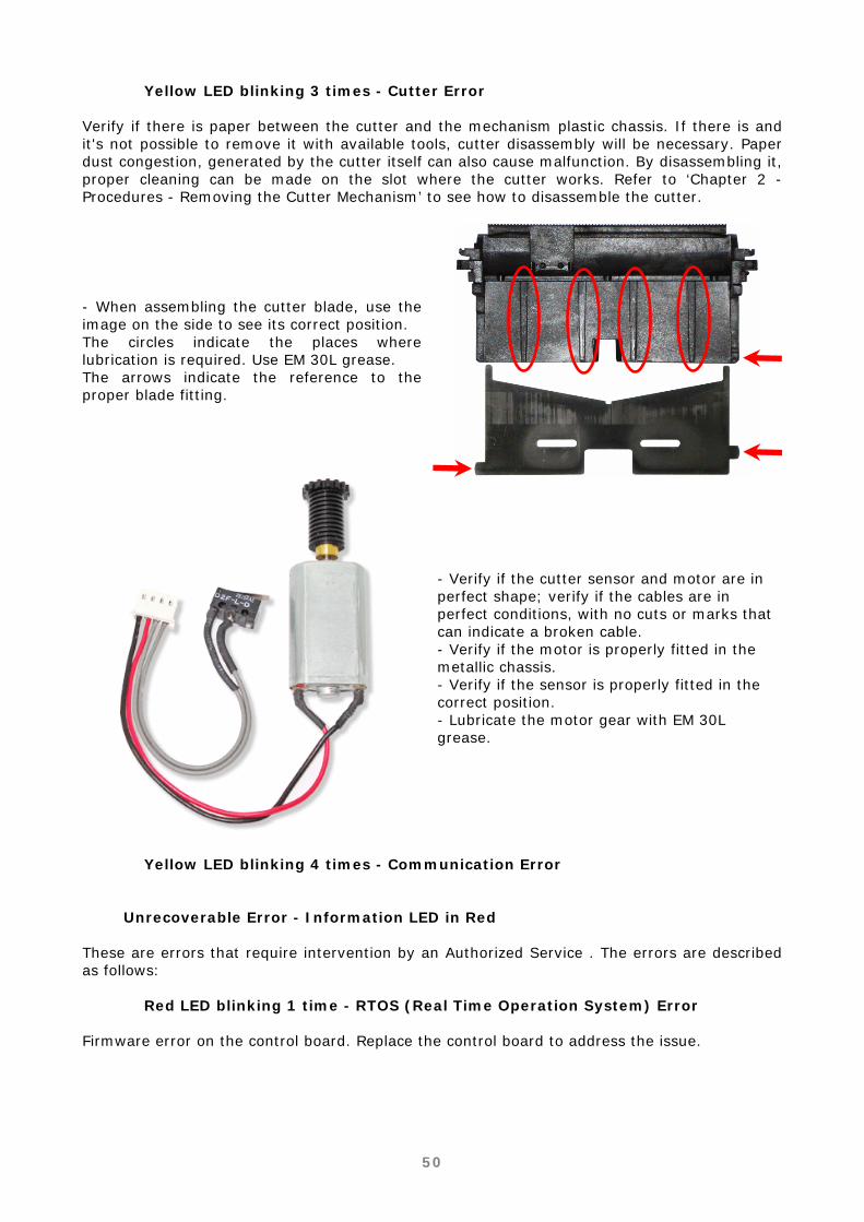
Yellow LED blinking 3 times - Cutter Error Verify if there is paper between the cutter and the mechanism plastic chassis. If there is and it's not possible to remove it with available tools, cutter disassembly will be necessary. Paper dust congestion, generated by the cutter itself can also cause malfunction. By disassembling it, proper cleaning can be made on the slot where the cutter works. Refer to ‘Chapter 2 - Procedures - Removing the Cutter Mechanism’ to see how to disassemble the cutter.
- When assembling the cutter blade, use the image on the side to see its correct position. The circles indicate the places where lubrication is required. Use EM 30L grease. The arrows indicate the reference to the proper blade fitting.
- Verify if the cutter sensor and motor are in perfect shape; verify if the cables are in perfect conditions, with no cuts or marks that can indicate a broken cable. - Verify if the motor is properly fitted in the metallic chassis. - Verify if the sensor is properly fitted in the correct position. - Lubricate the motor gear with EM 30L grease.
Yellow LED blinking 4 times - Communication Error
Unrecoverable Error - Information LED in Red These are errors that require intervention by an Authorized Service . The errors are described as follows:
Red LED blinking 1 time - RTOS (Real Time Operation System) Error Firmware error on the control board. Replace the control board to address the issue.

51
Red LED blinking 3 times - RAM Memory Error RAM memory error on the control board. Replace the control board to address the issue.
Red LED blinking 8 times - Print Mechanism Error On the print initialization, the status of the print head and the paper feed motor (picture below) are verified. At that moment, if one of these items does not respond, the print reports the print mechanism error through the Information LED. To correct the problem it will be
necessary to verify the following items: - Verify if the print head and the paper feed motor connection cables are in place and in perfect shape in all their length. - Verify if the control board cartridge is properly connected. If the problem persists, replace the print head or the paper feed motor, or both.
Red LED blinking 11 times - Low DC voltage sent by the power source To correct this problem, replace the AC adapter. If the error persists, replace the control board. There might be cases where the replacement of both items may be required.
Red LED blinking 12 times - Cutter Initialization Error
To correct any cutter problem, follow the steps of "Yellow LED blinking 3 times - Cutter Error"; if the problem persists, replace the motor set and the cutter sensor (picture on the side).

52
Troubleshooting
Problem Possible Cause Procedure
No power source. Verify if the electric switches are on. Connect any other equipment to verify if it works.
The Printer doesn't turn on Problem with the power source cable; it may be broken or unplugged.
Turn off the printer and verify the cable in all its length to be sure that it has no indication of physical damage. Verify if both ends of the cable are properly plugged.
The communication cable may be damaged or not properly plugged.
Verify the cable in all its length to be sure that it has no indication of physical damage. Verify if both ends of the cable are properly plugged.
The command sequence can be verified on the dump mode. Put the printer in dump mode and send the commands again. The printer will show all commands received in hexadecimal and ASCII.
The printer does not respond to commands
Wrong command sequence
Verify if the printer command set is properly configured. It can be configured as Bematech or ESC/POS™.
The communication cable may be damaged or not properly plugged.
Verify the cable in all its length to be sure that it has no indication of physical damage. Verify if both ends of the cable are properly plugged.
The communication cable pin layout is not in accordance with the defined protocol.
Verify if the cable pins position are correct, in accordance with the standards defined by the communication port. Verify also the configurations defined by the Dip Switches configurations, when referring to serial communication.
Communication problems
The baud rate is wrongly configured.
If the baud rate configured is different between the printer and the computer, the printer can print random characters or not print at all. Carefully verify the ports configuration between the printer and the computer or peripheral to which the printer is connected.
The LEDS are blinking The printer informs the status.
Refer to the "Indicative Lights" chart. If the light is yellow, it usually refers to an error that you can correct easily. If the light is red, refer to Chapter 3 to address the issue.
Paper dust and residues on the print head which can influence the print quality.
Clean the print head, as shown on the item "Cleaning Procedures" on this manual.
Wrong print density. You can configure the printing intensity. This configuration is important when different brands or kinds of paper are used.
Weak printing
Poor media quality Poor printing performance due to old thermal paper. Some thermal paper brands also have a weak printing output.
The paper doesn't come out of the printer
Paper jammed.
CAUTION! Do not touch the print head, as it can be very hot after printing. Wait for it to cool down before you touch it. Turn off the printer and open the cover, remove the paper roll and all the paper jammed inside the printer; put the paper roll back and turn the printer on.
Locked Cutter Blade Objects may be obstructing the blade path.
If the blade is blocked, turn the printer off and open the cover. Remove the objects that may be obstructing the blade, for example, a paper clip. Turn the printer back on and wait for the blade to return to its original position. The firmware will move the blade to its original position without the user's intervention. Close the cover and wait 3 seconds. If the problem persists, refer to Chapter 3 to see another way to address the issue.

53
Chapter 4 Technical Specifications Features: High performance, flexibility and easy operation are some of the features that make the thermal printer Bematech MP-4000 TH the cutting edge print solution to your retail outlet, where high quality, high speed, high reliability and reduced printing costs are priorities. Get to know some of the benefits that the MP-4000 TH can offer you: - reduced transaction time due to the high speed printing of 250mm/s, which allows more efficient transactions on the retail outlet; - reduced maintenance costs, simultaneously keeping the retail outlet operational for a longer period of time, due to a greater print head life and the cutter life cycle; - features as logo, graphics and bar code printing with higher quality, which allows for better coupon legibility, and more visibility and recognition for the brand; - less time to replace the paper roll and, therefore, more time available for processing transactions at the retail outlet. The MP-4000 TH works with paper rolls of up to 102 mm of diameter and also has an easy and fast paper roll change system (drop in / easy load); - versatility, as the MP-4000 TH can be configured to work with paper rolls in widths ranging from 58 mm up to 82.5 mm, which makes it appropriate for a broad range of applications; - retail outlet software - new and current - easy integration, due to its compatibility with the ESC/POSTM commands, and the Windows and Linux drivers availability; - the MP-4000 TH has a unique and exclusive system of failure recovery for jammed paper called ERS - Easy Recovery System, which ensures a quick and efficient return to an operational state; - exclusive cartridge system, MCS - Modular Cartridge System, which makes the electronic hardware independent from the printer body case, making maintenance easier and faster - therefore reducing the costs and the non-operational time.

54
Characteristics Specification
Method: Direct thermal line printing Printing Speed: 250 mm/s Paper Feed Speed: 59 lps Dot Density: 8 dots/mm (203 dpi x 203 dpi)
Paper Width (mm) Printing Width (mm) 58 48 (384 dots) 76 64 (512 dots) or 72 ( 576 dots) 80 Up to 76 (608 dots)
Printing Width:
82,5 Up to 80 (640 dots) Characters per Line: 24, 32, 48 e 64
Printing Characteristics
Characters Set: CODE 437, CODE 850, CODE 858 and CODE 860
- Bar Codes: EAN-8, EAN-13, CODE 39, CODE 93, CODE 128, ITF, CODABAR, UPC-A, UPC-E, ISBN, MSI, PLESSEY, PDF-417 - Cash Drawer Driver 01 RJ-12 connector - Serrated blade for paper cut
- Automatic Cutter - partial and full cut - Easy paper load (Drop in/ Easy loading) - Firmware update by user software - Bit Map Image Buffer, uploadable logos and character sets - Internal buzzer - Selectable font styles (Normal, Double High, Double Wide, Double High & Wide, Emphasized, Bold, Underlined, Italic, Inverted, Landscape) - Communication Interfaces: Serial (RS-232C), Parallel (IEEE1284), USB 2.0, Ethernet - Power Supply: Input: 100-240V~1,6A 50/60Hz Output: 24V-2,5A
Features
- Sensors: Paper End Sensor, Near End Paper Sensor, Top Cover Sensor Type: Thermal paper roll Width: 58 to 82.5 mm Diameter: Up to 102mm (4 inches)
Media
Thickness: 56 to 107 microns Printer Head Service Lifetime 150 km
Reliability Cutter Lifetime 2 million cuts Operating temperature 0 a 50 ºC
Environment Operating Humidity 10 a 90% RH (non condensing)
Physical Characteristics
Dimensions: 146 mm (height) x 150 mm (width) x 218 mm (depth) Mass: 1.2 kg
Software and Drivers Windows 95(2) / 98(2) / ME™(2), NT 4.0™(2), Windows2000™, Windows XP™, Linux CUPS™(3). User’s Software.
Available Accessories (1) Power Supply, Communication Cable, Thermal paper roll.
(1) Please contact Bematech to consult the availability of the interfaces and accessories. (2) It works only with Serial and Ethernet communication interfaces. (3) It doesn't work with USB communication interface.


![Marketing Variable Produto[1]](https://static.documents.pub/doc/80x56/577c80b51a28abe054a9d6cb/marketing-variable-produto1.jpg)


