Lesson Objective:In this lesson, we will learn how to create servo motors, and run a simpleanimation and play back the results. In Pro/ENGINEER, there are two different modules th at will create animations of assemblies. The first is Mechanism, which we are learning about in this class, and the second is Design Animation. Lesson http://sharptechdesign.com/Tutorials/Mechanism_WF2/MDX_WF2_Less... 1 of 14 05-Apr-11 8:55 PM
The two packages go hand-in-hand, but the animation capability in Mechanism is really referred to as an
Analysis, which we will learn about briefly in this lesson, and in more detail later on.
Design Animation is designed to create complex animations, not only based on the allowable movement of
an assembly as defined in Mechanism, but also exploded assembly and disassembly animations, which cannot be done in Mechanism.
Out of the box, the default animation time in Mechanism is 10 seconds. This is important to know, because
the values that we will use when defining our servo motors will rely heavily on how much time we are goingto animate the specific motor, and the range of motion we want it to capture in that time.
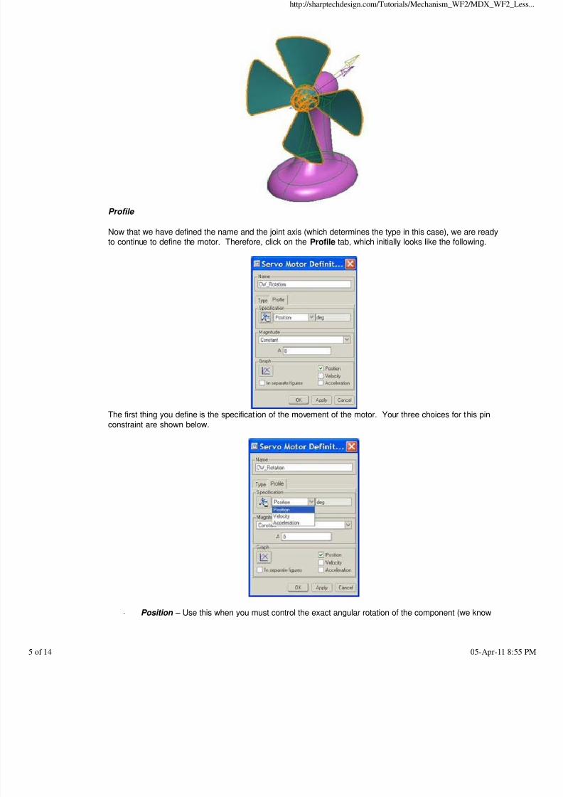
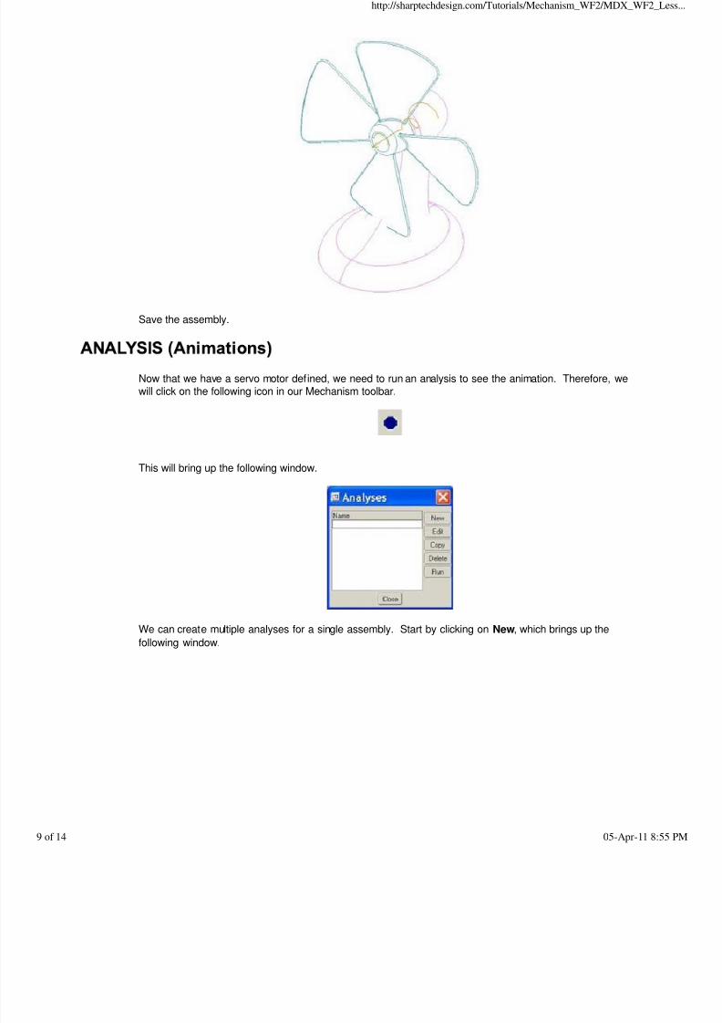
To demonstrate Servo Motors and basic animation, we will start with our Fan assembly that we worked with
in an earlier lesson, which looks like the following.
If you remember from Lesson 2, we reset the zero location so the blades would be straight up and down,but we never specified that we wanted to use “0” for regenerations. Therefore, that will be the first thing we
will do, just so we can always return to the absolute zero position.
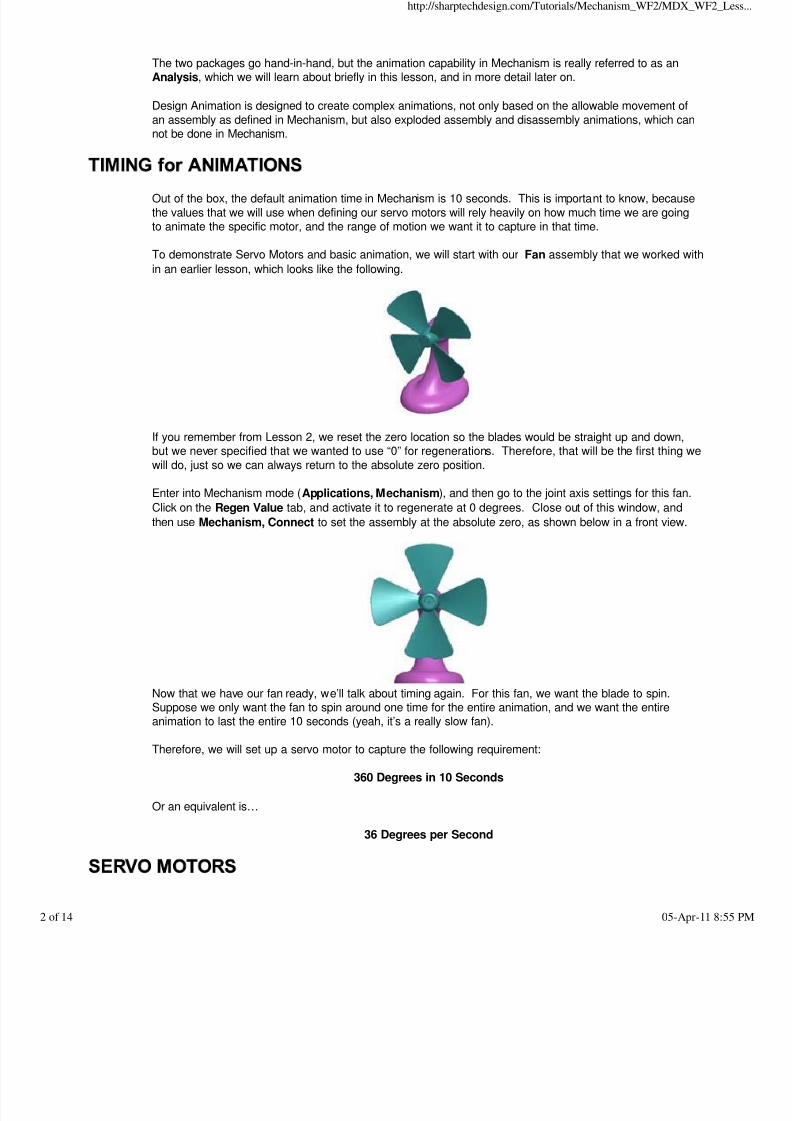
Enter into Mechanism mode (Applications, Mechanism), and then go to the joint axis settings for this fan.
Click on the Regen Value tab, and activate it to regenerate at 0 degrees. Close out of this window, and
then use Mechanism, Connect to set the assembly at the absolute zero, as shown below in a front view.
Now that we have our fan ready, we’ll talk about timing again. For this fan, we want the blade to spin.
Suppose we only want the fan to spin around one time for the entire animation, and we want the entireanimation to last the entire 10 seconds (yeah, it’s a really slow fan).
Therefore, we will set up a servo motor to capture the following requirement:
There are two types of motors in Mechanism, Servo and Force. We will concentrate mostly on the servomotor in this lesson.
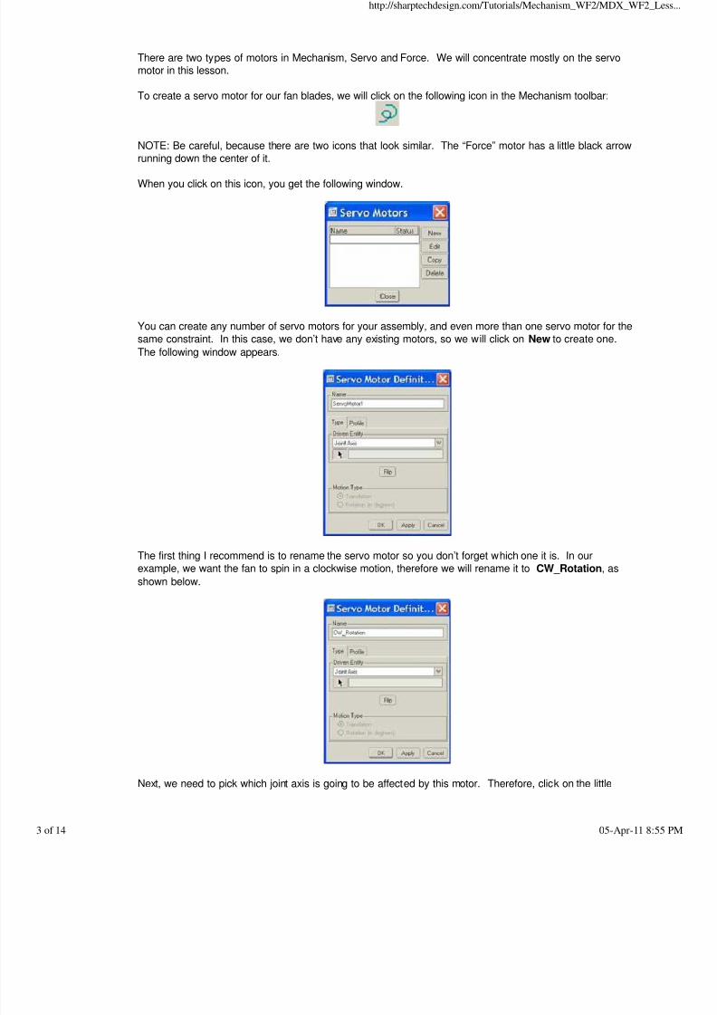
To create a servo motor for our fan blades, we will click on the following icon in the Mechanism toolbar:
NOTE: Be careful, because there are two icons that look similar. The “Force” motor has a little black arrow
running down the center of it.
When you click on this icon, you get the following window.
You can create any number of servo motors for your assembly, and even more than one servo motor for thesame constraint. In this case, we don’t have any existing motors, so we will click on New to create one.
The following window appears.
The first thing I recommend is to rename the servo motor so you don’t forget which one it is. In our
example, we want the fan to spin in a clockwise motion, therefore we will rename it to CW_Rotation, as
shown below.
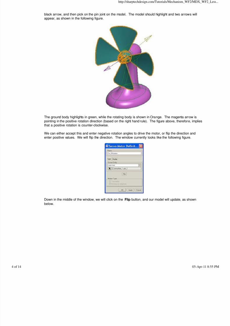
Next, we need to pick which joint axis is going to be affected by this motor. Therefore, click on the little
black arrow, and then pick on the pin joint on the model. The model should highlight and two arrows willappear, as shown in the following figure.
The ground body highlights in green, while the rotating body is shown in Orange. The magenta arrow is
pointing in the positive rotation direction (based on the right hand rule). The figure above, therefore, impliesthat a positive rotation is counter-clockwise.
We can either accept this and enter negative rotation angles to drive the motor, or flip the direction and
enter positive values. We will flip the direction. The window currently looks like the following figure.
Down in the middle of the window, we will click on the Flip button, and our model will update, as shown
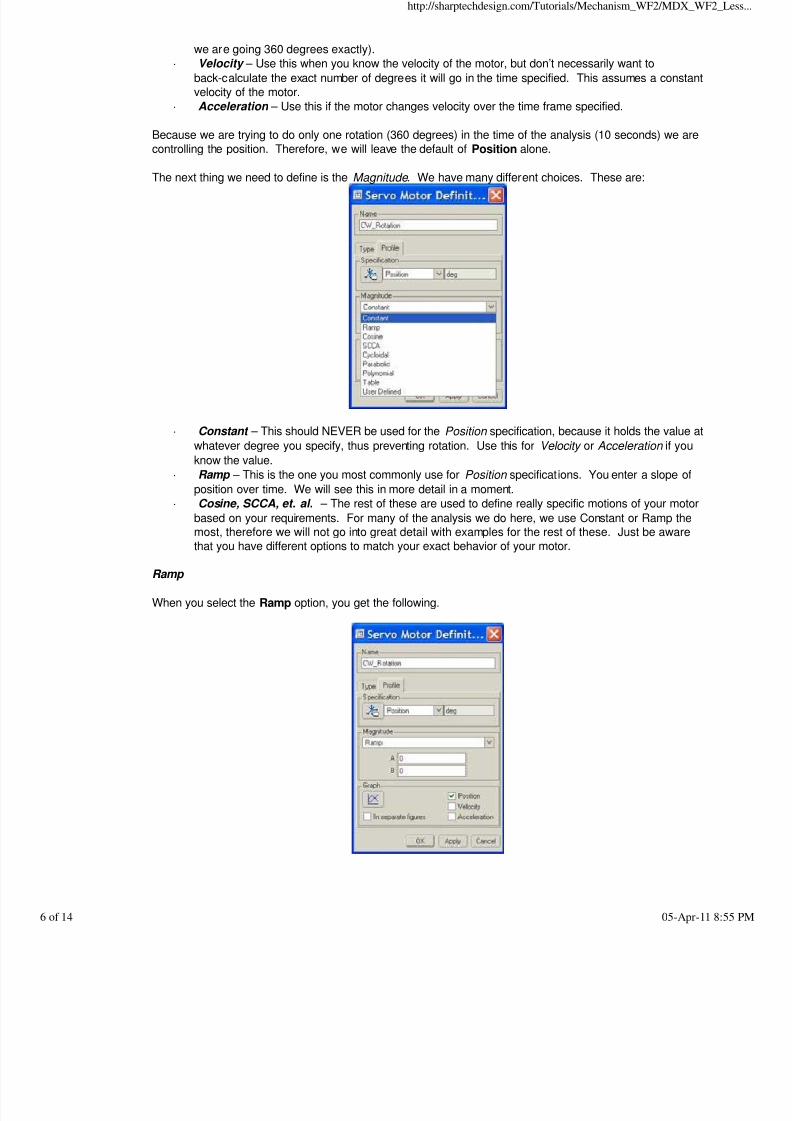
Now that we have defined the name and the joint axis (which determines the type in this case), we are readyto continue to define the motor. Therefore, click on the Profile tab, which initially looks like the following.
The first thing you define is the specification of the movement of the motor. Your three choices for this pin
constraint are shown below.
· Position – Use this when you must control the exact angular rotation of the component (we know
· Velocity – Use this when you know the velocity of the motor, but don’t necessarily want to
back-calculate the exact number of degrees it will go in the time specified. This assumes a constant
velocity of the motor.
· Acceleration – Use this if the motor changes velocity over the time frame specified.
Because we are trying to do only one rotation (360 degrees) in the time of the analysis (10 seconds) we are
controlling the position. Therefore, we will leave the default of Position alone.
The next thing we need to define is the Magnitude . We have many different choices. These are:
· Constant – This should NEVER be used for the Position specification, because it holds the value at
whatever degree you specify, thus preventing rotation. Use this for Velocity or Acceleration if you
know the value.
· Ramp – This is the one you most commonly use for Position specifications. You enter a slope of
position over time. We will see this in more detail in a moment.
· Cosine, SCCA, et. al. – The rest of these are used to define really specific motions of your motor
based on your requirements. For many of the analysis we do here, we use Constant or Ramp the
most, therefore we will not go into great detail with examples for the rest of these. Just be awarethat you have different options to match your exact behavior of your motor.
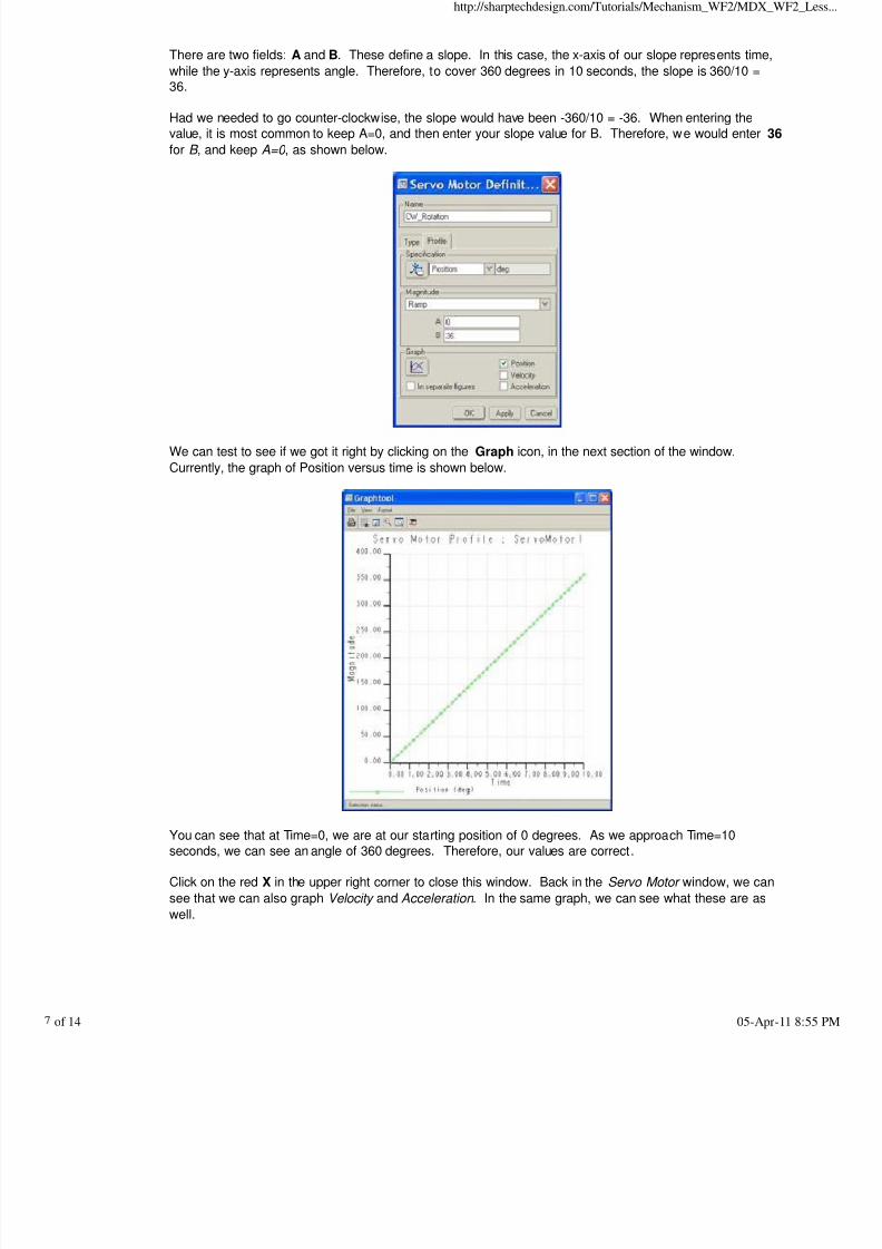
Ramp
When you select the Ramp option, you get the following.
There are two fields: A and B. These define a slope. In this case, the x-axis of our slope represents time,
while the y-axis represents angle. Therefore, to cover 360 degrees in 10 seconds, the slope is 360/10 =36.
Had we needed to go counter-clockwise, the slope would have been -360/10 = -36. When entering the
value, it is most common to keep A=0, and then enter your slope value for B. Therefore, we would enter 36
for B , and keep A=0 , as shown below.
We can test to see if we got it right by clicking on the Graph icon, in the next section of the window.
Currently, the graph of Position versus time is shown below.
You can see that at Time=0, we are at our starting position of 0 degrees. As we approach Time=10
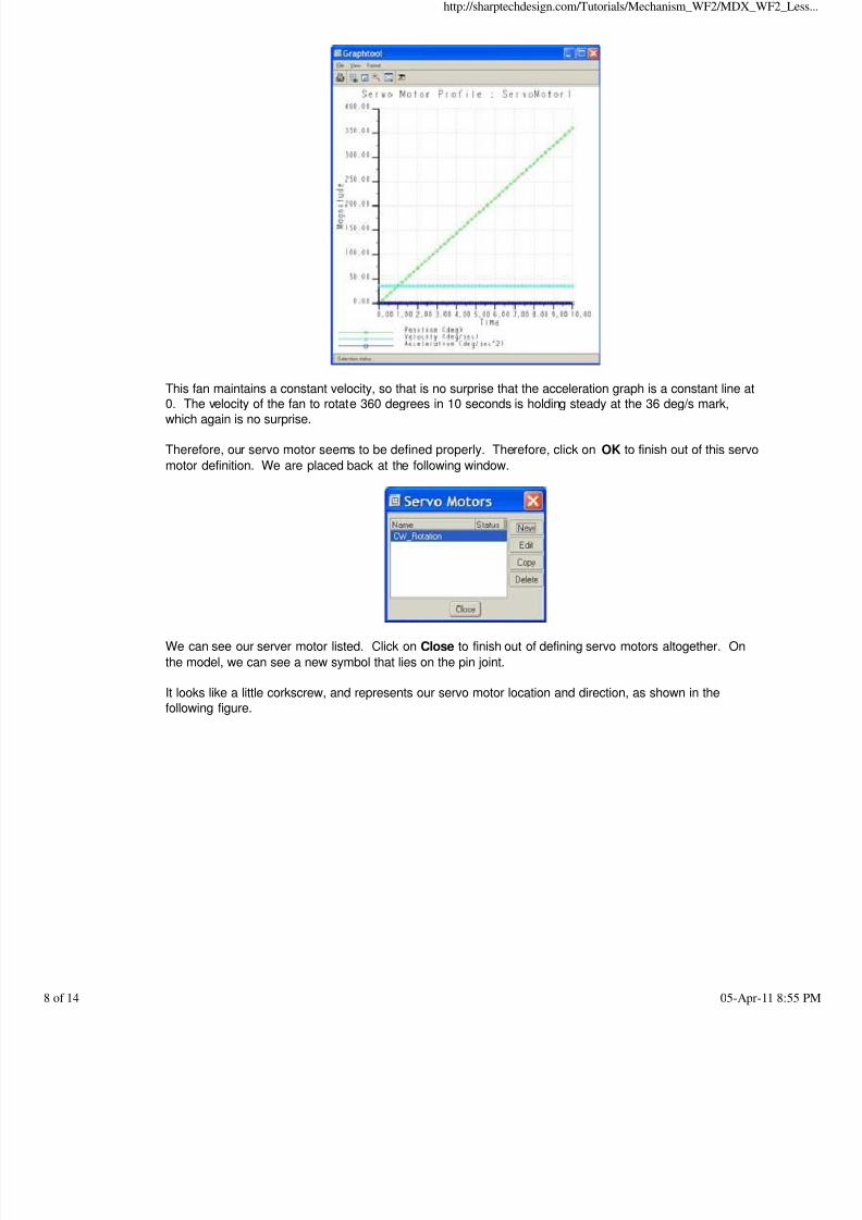
seconds, we can see an angle of 360 degrees. Therefore, our values are correct. Click on the red X in the upper right corner to close this window. Back in the Servo Motor window, we can
see that we can also graph Velocity and Acceleration . In the same graph, we can see what these are as
This fan maintains a constant velocity, so that is no surprise that the acceleration graph is a constant line at0. The velocity of the fan to rotate 360 degrees in 10 seconds is holding steady at the 36 deg/s mark,
which again is no surprise.
Therefore, our servo motor seems to be defined properly. Therefore, click on OK to finish out of this servo
motor definition. We are placed back at the following window.
We can see our server motor listed. Click on Close to finish out of defining servo motors altogether. On
the model, we can see a new symbol that lies on the pin joint.
It looks like a little corkscrew, and represents our servo motor location and direction, as shown in the
Now that we have a servo motor defined, we need to run an analysis to see the animation. Therefore, wewill click on the following icon in our Mechanism toolbar.
This will bring up the following window.
We can create multiple analyses for a single assembly. Start by clicking on New, which brings up the
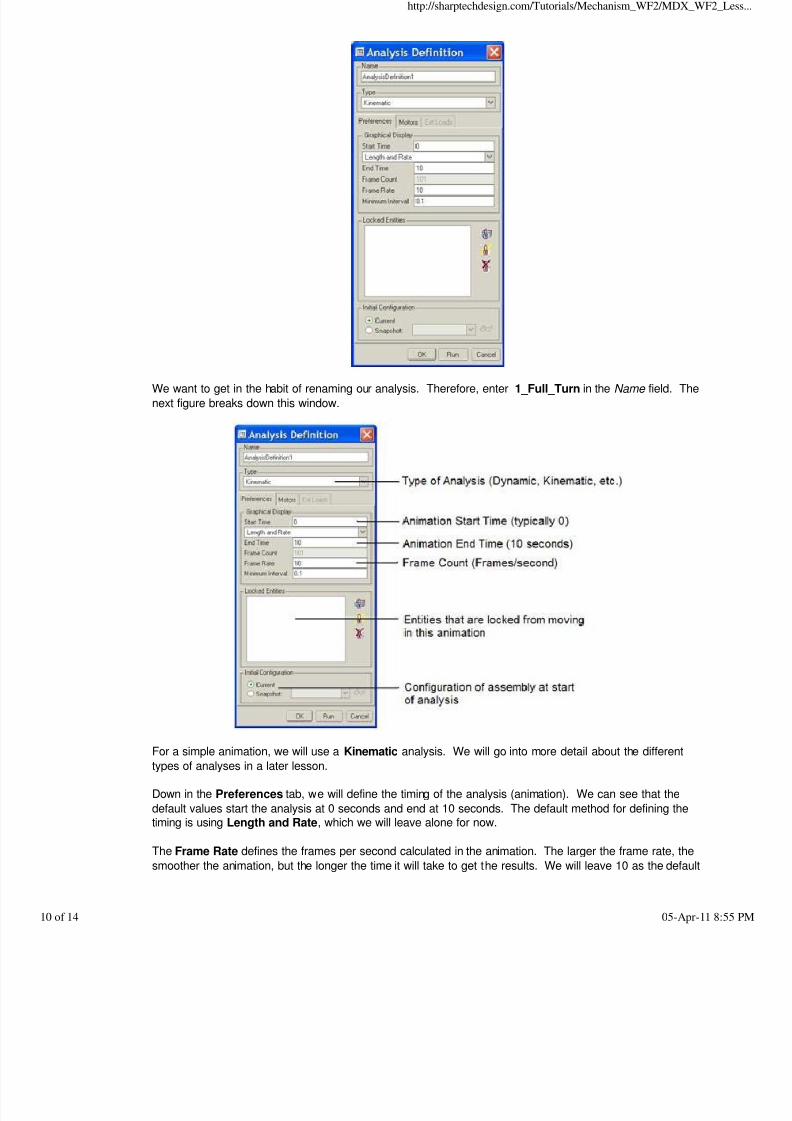
We want to get in the habit of renaming our analysis. Therefore, enter 1_Full_Turn in the Name field. The
next figure breaks down this window.
For a simple animation, we will use a Kinematic analysis. We will go into more detail about the different
types of analyses in a later lesson.
Down in the Preferences tab, we will define the timing of the analysis (animation). We can see that the
default values start the analysis at 0 seconds and end at 10 seconds. The default method for defining thetiming is using Length and Rate, which we will leave alone for now.
The Frame Rate defines the frames per second calculated in the animation. The larger the frame rate, the
smoother the animation, but the longer the time it will take to get the results. We will leave 10 as the default
for now. In the next section, we can use the familiar Lock/Unlock bodies constraint that we saw in the drag window.
Most of the time, unless you are just testing a servo motor, you will let the entire assembly run through theanimation.
Finally, you can specify how the analysis starts. The reason we set the regeneration value at 0 for our joint
axis is so we could use Mechanism, Connect to define our starting position for our animation. That would
correspond to Current in the selection box.
Be careful, however. If you do not “Connect” up your assembly, the animation will start at the exact location
it is currently sit ting, which could cause a problem if you have limits set. You can also use an existingsnapshot to define the starting position of the components in the assembly.
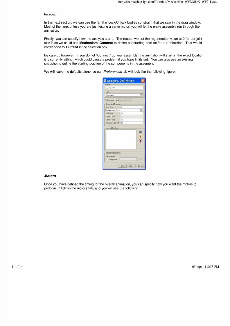
We will leave the defaults alone, so our Preferences tab will look like the following figure.
Motors
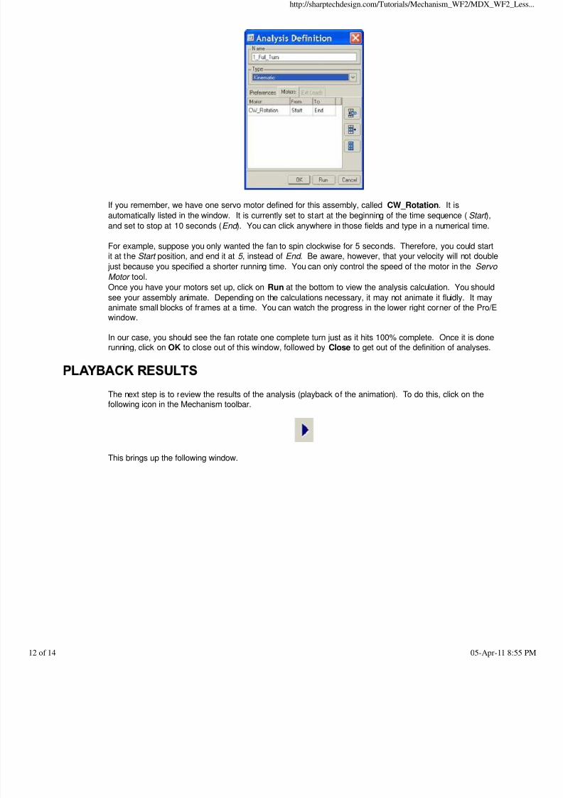
Once you have defined the timing for the overall animation, you can specify how you want the motors toperform. Click on the motors tab, and you will see the following.
If you remember, we have one servo motor defined for this assembly, called CW_Rotation. It is
automatically listed in the window. It is currently set to start at the beginning of the time sequence (Start ),
and set to stop at 10 seconds (End ). You can click anywhere in those fields and type in a numerical time.
For example, suppose you only wanted the fan to spin clockwise for 5 seconds. Therefore, you could start
it at the Start position, and end it at 5 , instead of End . Be aware, however, that your velocity will not doublejust because you specified a shorter running time. You can only control the speed of the motor in the Servo
Motor tool.
Once you have your motors set up, click on Run at the bottom to view the analysis calculation. You should
see your assembly animate. Depending on the calculations necessary, it may not animate it fluidly. It may
animate small blocks of frames at a time. You can watch the progress in the lower right corner of the Pro/Ewindow.
In our case, you should see the fan rotate one complete turn just as it hits 100% complete. Once it is donerunning, click on OK to close out of this window, followed by Close to get out of the definition of analyses.
The next step is to review the results of the analysis (playback of the animation). To do this, click on thefollowing icon in the Mechanism toolbar.
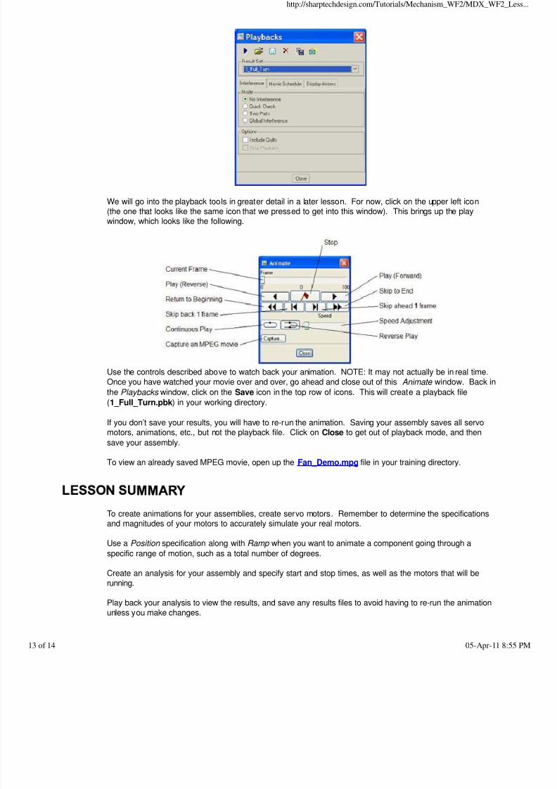
We will go into the playback tools in greater detail in a later lesson. For now, click on the upper left icon(the one that looks like the same icon that we pressed to get into this window). This brings up the playwindow, which looks like the following.
Use the controls described above to watch back your animation. NOTE: It may not actually be in real time.Once you have watched your movie over and over, go ahead and close out of this Animate window. Back in
the Playbacks window, click on the Save icon in the top row of icons. This will create a playback file
(1_Full_Turn.pbk) in your working directory.
If you don’t save your results, you will have to re-run the animation. Saving your assembly saves all servomotors, animations, etc., but not the playback file. Click on Close to get out of playback mode, and then
save your assembly.
To view an already saved MPEG movie, open up the Fan_Demo.mpg file in your training directory.
To create animations for your assemblies, create servo motors. Remember to determine the specificationsand magnitudes of your motors to accurately simulate your real motors.
Use a Position specification along with Ramp when you want to animate a component going through a
specific range of motion, such as a total number of degrees.
Create an analysis for your assembly and specify start and stop times, as well as the motors that will be
running. Play back your analysis to view the results, and save any results files to avoid having to re-run the animation
Go back to this fan assembly and redefine the servo motor to run at a velocity of 1200 RPM. Create an
animation for 10 seconds based on this new motor. Save your results that you get from the playback. HINT: Make sure that it is still going clockwise, and you may need to bump up your frame rate to 100
frames per second to see any movement.
Zero_Refs
Create an animation for this assembly to open the lid from the closed position over a span of 5 seconds,then completely close it over another 5 seconds, thus creating a 10 second animation.
HINT: You will need two different motors to accomplish this task, one that moves in a CW direction, andanother that moves in a CCW direction.