PROGRESS OF THE LASSO EXPERIMENT " fir; B.E.H. SERENE European Space Agency, Toulouse, France ABSTRACT " ! . ' -' ' '> . " .• ' The LASSO (Laser Synchronisation from Stationary Orbit) experiment has been designed to demonstrate the feasibili- ty of achieving time synchronisation between remote atomic clocks with an accuracy of one nanosecond or better by using laser techniques for the first time. The experiment uses ground- based laser stations and the SIRIO-2 geostationary satellite, to be launched by ESA towards the end of 1981. The first part of the paper is dedica- ted to the qualification of the LASSO on-board equipment, with a brief des- cription of the electrical and optical test equipment used. The second part gives the progress of the operational organisation since the last PTTI meeting, including the pro- visional list of participants. 1. INTRODUCTION Since the last PTTI meeting an important number of activi- ties have taken place in the framework of the SIRIO-2 programme and more specifically for the LASSO experiment - the units of the mechanical model have been integrated and successfully tested with the complete satellite, - a design review has been held to examine breadboard results with a view of authorising the manufacture of the qualification units, 307 https://ntrs.nasa.gov/search.jsp?R=19810018944 2018-06-25T18:38:31+00:00Z
Transcript
PROGRESS OF THE LASSO EXPERIMENT
" fir; B.E.H. SERENE
European Space Agency, Toulouse, France
ABSTRACT" ! . ' -' ' '> . " .• '
The LASSO (Laser Synchronisation fromStationary Orbit) experiment has beendesigned to demonstrate the feasibili-ty of achieving time synchronisationbetween remote atomic clocks with anaccuracy of one nanosecond or betterby using laser techniques for the firsttime. The experiment uses ground-based laser stations and the SIRIO-2geostationary satellite, to be launchedby ESA towards the end of 1981.
The first part of the paper is dedica-ted to the qualification of the LASSOon-board equipment, with a brief des-cription of the electrical and opticaltest equipment used.
The second part gives the progress ofthe operational organisation since thelast PTTI meeting, including the pro-visional list of participants.
1. INTRODUCTION
Since the last PTTI meeting an important number of activi-ties have taken place in the framework of the SIRIO-2programme and more specifically for the LASSO experiment
- the units of the mechanical model have been integratedand successfully tested with the complete satellite,
- a design review has been held to examine breadboardresults with a view of authorising the manufactureof the qualification units,
the units of the qualification model have been deliveredto the Centre National d'Etudes Spatiales (CNES) forintegration and performance evaluation at subsystemlevel,after acceptance of the principal investigators by ESA,two LASSO Experimenters and Users Team (LEOT) meetingswere held in Geneva and Paris respectively*the LASSO Coordination Centre (LCC) was subcontractedto the Italian firm TELESPAZIO which is already incharge of the SIRIO-2 Operations Control Centre {SIQCC) .
2. QUALIFICATION OF THE LASSO PAYLOAD
2.1. LASSO On-Board Equipment
The specifications and the design concept were largelypresented at the last PTTI meeting (1). It is recalledthat the LASSO payload consists of :
- the retro-refleetors,- the photo-detectors for sensing ruby and neodyme laserpulses,
- the ultra-stable oscillator,- the counter to time-tag the arrival of the pulses.
These time-tags are to be encoded in time divisionmultiplex with satellite housekeeping before transmissionto the ground.An overall block diagram is shown in Figure 1.
2.2. LASSO Test Equipment
The test equipment has been designed and built for easytransportation and operation with a maximum of automatictest sequences. It is used at :
- subsystem level for qualification and acceptancetests,
- system level for integration and pre-launch tests,
and consists of two inter-connected parts : the electricaltest equipment (ETE) and the optical test equipment (OTE).
(1) SERENE B. and ALBERTINOLI P.t"The LASSO Experiment on the SIRIO-2 Spacecraft", ESA Journal,Vol. 4, pages 59 to 72, 1980
In order to allow a complete check of the LASSO pay load,the ETE must perform the following functions :
(a) satellite interface simulation concerning powersupply, telecommand transmission, telemetry acqui-sition and synchronisation with satellite rotation.
(b) laser pulse simulation by means of an electricalpulse generator which is used directly behind thephoto-detectors or indirectly to trigger theOTE. In both cases, stimuli pulses are time-taggedby the ETE; these measures are used as referencesto verify those carried out by the LASSO equipment.
(c) LASSO housekeeping monitoring; this function concernstemperatures, voltages, currents and statusrecognition.
(d) interface with the satellite check-out equipmentafter integration of the LASSO payload in thesatellite.
Overall control of the ETE is performed by a desk-topcomputer running automatic and semi-automatic testsequences and providing finally statistical treatment ofthe measurements performed .
An overall block diagram is shown in Figure 2.
2.2.2. 2Etical_tes t
The OTE, under ETE software control, sends laser pulsestowards LASSO detectors and simulates the light generatedby the earth albedo inside a time window corresponding toearth visibility.
The departure of the laser pulses are detected in the OTEby fast photo-diodes which provide an electrical feed-back signal time-tagged by the ETE.
The block diagram of the OTE is given in Figure 3, and themain characteristics of the different parts are listedbelow :
(c) earth albedo simulator where a quartz-iodine lampprovides the illumination :
222 yW/cm for X + 6 nm2
16 yW/cm for X~ + 6 nm
(d) optical interface which collects, by means of opticalfibers, the light generated by the three simulatorsabove; after being mixed and merged into a parallelbeam, the light is chopped by a mechanical shutterdriven by the earth appearence signal.
(e) electrical interface between the OTE and the ETE.
Pulse width half amplitude
313
2.3. LASSO Units Test
2.3.1. Retro-reflectors
The qualification programme was run by AEROSPATIALE on atest sample made of 94 dummy glass corner cubes and4 flight-worthy quartz corner cubes. The diffractionfigures of the 4 quartz corner cubes were measured beforeand after each test :
- vibration (sinusoidal and random)- thermal cycle under vacuum (+50°C/ -60°C)
The measured efficiency for normal incidence is in fact20 for 694.3 nm and 17.5 for 532 nm;
2.3.2. Optics
The qualification programme on the two sets of opticswas conducted by MATRA and EMD.For the neodyme optics the results are :
- normal incidence A = 534.3 nm with a bandwidth (halfamplitude) of 11.8 nm;
- 10 degrees incidence introduce a shift of the centralwavelength of -2,3 nm; the bandwidth remains the same;
- the optical gain versus incidence angle was measuredand the results are given in Figure 4 and 5;
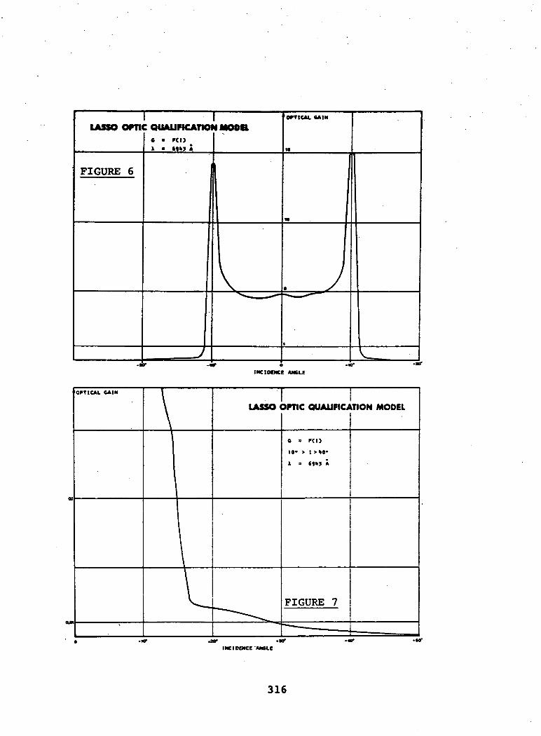
For the ruby optics the results are :
- normal incidence A = 696.9 nm with a bandwidth (halfamplitude) of 12.1 nm;
-10 degrees incidence introduce a shift of the centralwavelength of -2.5 nm, the bandwidth remaining the same;
- the optical gain versus incidence angle was measuredand the results are given in Figures 6 and 7.
2.3.3. Ultra-Stable_gscillator (U.S.O;.)
This unit, manufactured by F.E.I. (USA), was deliveredfully qualified.
314
ILASSO OPTIC QUALIFICATION MODEL6 = Kl)
> = »20 A
OPTICAL CAIN
FIGURE 4
INCIDENCE ANGLE
LASSO OPTIC QUALIFICATION MODEL
315
I ILASSO OPTIC QUALIFICATION MODIL
INCIDENCE AMBLE
LASSO OPTIC QUALIFICATION MODEL
INCIDENCE 'ANCie
316
2.3.4. Converter
The qualification programme was conducted by LABEN andthe following test sequence was applied :
- electrical performance,- vibration (sinusoidal and random),'.- electrical performance,- thermal cycles under vacuum <+60t*C, -20°C)- final electrical performance.
2.3.5. Detection_and_datation
The qualification programme was conducted by EMD on bothunits, using only the ETE. The following test sequencewas applied :
- electrical performance,- vibration (sinusoidal and random),
The electrical performance was controlled for sixdifferent configurations which are listed below :
Configu-ration
1
2
3
4
Pulsewidth
(halfamplitude)
(nsec)
2
20
Time Sep-arationbetween2 pulsesof a same
pair(msec)
0.284
72.7
0.284
72.7
Time Sep-arationbetween2 pairs
(msec)
1164
Pulseamplitude
(mV)
200
8 000
Time Sep-arationbetween2 se-quences
(msec)
70
317
A 5th configuration is used for false detection evaluation,with and without the presence of the earth albedo, during aperiod of five minutes.
Yet another configuration. No. 6, is used for the chronometerdead-time evaluation, i.e. time tagging pulses far apartof 200 ysec.
The results obtained for the different configurations aresummarised in the Table 1.
Confi-guration
1
2
3
4
1
2
3
4
5
5
1
2
3
4
5
6
sensitivity
normaliin
H
maximalMn
ii
nn
normaln
ii
n
n
albedo
noii
n
ii
yesnn
n
n •
noyes
M
nn
n
Standarddeviation(psec)
148377
137
456
159
280
141
296
-
-
185
286
145
240
-
Falsedetection
-
--
-
-
-.--
0
0
- -
-
-
- • '•'
0
Operating properly
TABLE 1
318
2.4. LASSO Subsystem Test
For this purpose a satellite mock-up was manufactured,enabling the units to be mounted in their exact position.
After delivery to CNES, the 'detection, the datation andthe ultra-stable oscillator were integrated on the mock-up and inter-connected with the qualification modelharness. This partial subsystem was submitted to thermalcycle under vacuum (+50°C, -10°C) during which-the elec-trical performance was extensively controlled using theOTE and ETE. .
The main results are :
- for 1900 pairs of pulses generated by the neodyme andthe ruby laser simulators, in all the configurations,the standard deviation is 341 psec with a bias of68 psec due to the fact that two different time refe-rences are used.
- the number of false detections is always less than oneper hour.
After delivery to CNES, the converter was integrated inthe partial subsystem. The test programme for the quali-fication of the complete subsystem is at present ongoingwith the following activities :
- electrical performance,- electromagnetic compatibility, including electrostatictest, :
- thermal cycles,- final electrical performance.
3. OPERATIONAL ORGANISATION
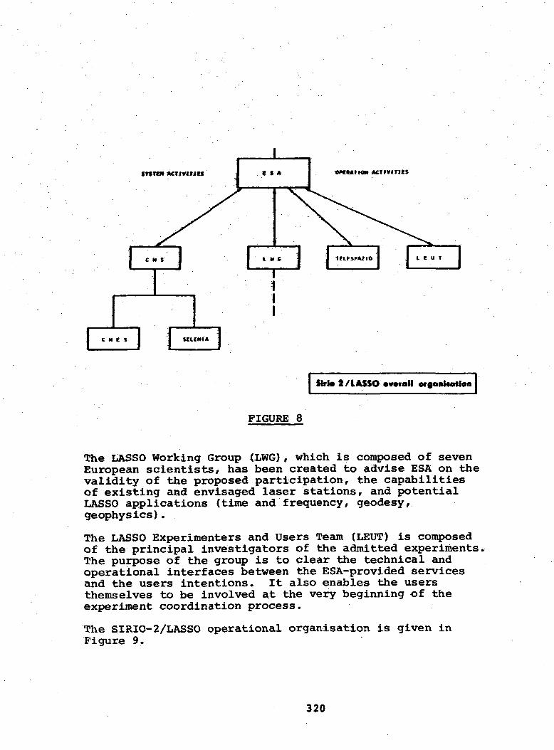
The overall SIRIO-2/LASSO organisation -is shown inFigure 8.
The industrial consortium is led by the CompagniaNazionale Satelliti per Telecommunicazioni (CNS) withtwo co-contractors, CNES and SELENIA, in charge of theLASSO and MDD payloads recpectively, while for the ope-rational activities the company TELESPAZIO has beenentrusted, under ESA contract, to run the SIOCC and the LCC,
319
srsrc*
1 t If C
1r14
i I ifirspAjio
Strl» 2/lASSO •vvroll organttatfon
FIGURE 8
The LASSO Working Group (LWG), which is composed of sevenEuropean scientists, has been created to advise ESA on thevalidity of the proposed participation, the capabilitiesof existing and envisaged laser stations, and potentialLASSO applications (time and frequency, geodesy,geophysics).
The LASSO Experimenters and Users Team (LEUT) is composedof the principal investigators of the admitted experiments.The purpose of the group is to clear the technical andoperational interfaces between the ESA-provided servicesand the users intentions. It also enables the usersthemselves to be involved at the very beginning of theexperiment coordination process.
The SIRIO-2/LASSO operational organisation is given inFigure 9.
320
s e n ' L I K K SSIRIO-I OPERATIONS
COHTROl CENTRE (SIOCC)I
LASSO COORDINATIONCENTRE (LCC)
S C I E N T I F I C C O M M U N I T Y
I Slrlo 2/LASSO operational organUatlon
FIGURE 9
3.1. The Scientific Community
The Announcement of Opportunity was issued by ESA inSeptember 1979 and distributed worldwide. Replies werereceived and analysed with the support of the LWG duringthe first quarter 1980. Provisional admittances werenotified to the principal investigators, and two LEUTmeetings were held in June and September 1980.
The provisional list of participants in the LASSOmission is given in Table 2.
Data exchange between LCC, laser stations, time institutesand research laboratories will, as far as practicable, takeplace using the worldwide General Electric Mark III System.
Specialised or validative data processing will be performedby various user institutes primarily to satisfy their ownneeds, but the results will be made available to the usercommunity as a whole by way of the G.E. Mark III fileinterrogation feature.
The LCC data output will consist of laser transmissionand reception times at the participating laser stations,along with the datation extracted from the satellitetelemetry. The data will be distributed to principalinvestigators via the G.E. Mark III System.
3.4. Cooperation with the "Bureau Internationalde 1'Heure" (BIH)
The BIH has offered its cooperation with ESA in the LASSOmission in three areas :
- time comparison over long periods, by statisticaltreatment, for atomic clocks attached to laser stations;
- special processing allowing the participation ofone-way laser stations;
- data exchange via the G.E. Mark III System.
3.5. ESA Responsibility
The LASSO principal tasks to be carried out by ESA underthe SIRIO-2 Exploitation Phase during 24 months aftergeosynchronous orbit acquisition are :
(a) schedule and prepare the overall LASSO mission interms of monthly, weekly and daily activities, inliaison with participating principal investigatorsand laser station operators;
324
(b) build, operate and maintain a LASSO CoordinationCentre (LCC);
(c) collaborate with LASSO Principal Investigators in thecalculation of time asynchronisms among participatingatomic clocks with the aim of demonstrating thefeasibility of achieving a precision of one nanosecondor better;
(d) transport and maintain a transportable calibrationdevice in order to monitor secular drift phenomenain the laser transmission and reception equipmentat participating laser stations;
(e) evaluate and report on the performances of the LASSOmission in comparison with other space and groundmethods for time transfer.
4. CONCLUSION
The testing of the LASSO qualification model and themanufacturing of the flight model hardware is progressingin a satisfactory manner.
The LASSO mission implementation is facilitated by theoverwhelming support of users, consisting mainly of laserstation operators, time and frequency institutes, andresearchers in the field of geodesy and geophysics.
The LASSO exploitation is benefitting from the fact thatthe users have developed, over the years, an informalbut well-established scientific and operational relation-ship as a result of earlier land and space programmes.
Accordingly, users in Europe, America and Asia are under-taking procurement or adaptation of ground hardware, alongwith software development, in order to render the LASSOmission and their own participation as fruitful andrewarding as possible.
- oOo -
325
QUESTIONS AND ANSWERS
PROFESSOR CARROLL ALLEY, University of Maryland
Could you give us more details on the results of the testing, par-ticularly as to the minimum detectable signal in the presence ofmaximum Albedo and in the presence of minimum Albedo?
DR. SERENE:
Well, I am surprised you have any questions, Professor, but no Idon't have this information here. Have you any problem concerningthe detection level? Because as far as I understand you plan touse a quite powerful laser and you have more problem to avoid de-stroying the equipment on-board than to know the threshold.
PROFESSOR ALLEY:
We need to know both. Let me go a bit further. You reported thatthe false alarm turns out to be at a rate of less than one per hour,whereas the specifications call for one per minute. This suggeststo me that perhaps the threshold levels for detection is set higherthan it might be necessary and that one might have a better sensi-tivity if one adjusted that.
DR. SERENE:
Well, the threshold detection is just to avoid filling the memorywith any stray lights, but actually that is not involved in thethreshold for the detection of the laser pulse because we have twomodes. The normal mode and the sensitive mode on-board, and Idon't see the point, because the spec for one false detection perminute is more to limit electronic noise than light noise.
PROFESSOR ALLEY:
Well, I would think that they would get mixed up at the final level.Perhaps we should continue this discussion elsewhere.
DR. SERENE:
Yes, no problem. But, we can have electronic noise and passivelight. That is where the false detection comes from, because ifyou have something recorded in the memory perhaps not coming fromthe detection, but coming by electromagnetic coupling that is afalse detection. It has nothing to do with the threshold.
326
PROFESSOR ALLEY:
Well, I think this is not the forum to continue this detail but letus continue it later.