Proc. SPIE Vol. 5904, p. 281-292, Cryogenic Optical Systems and Instruments XI Progress on Smart Focal Plane Technologies for Extremely Large Telescopes Colin Cunningham *a , Eli Atad a , Jeremy Bailey b , Fabio Bortolleto c , Francisco Garzón d , Peter Hastings a , Roger Haynes b , Callum Norrie a , Ian Parry e , Eric Prieto f , Suzanne Ramsay Howat a , Juergen Schmoll g , Lorenzo Zago h , Frederic Zamkotsian i a UK Astronomy Technology Centre, Royal Observatory Edinburgh, EH9 3HJ, UK b Anglo Australian Observatory, 167 Vimidra Rd, Eastwood, NSW 2112, Australia c INAF -Astronomical Observatory of Padova, Vicolo dell'Osservatorio 5, I-35122 Padova, Italy d Instituto Astrofisica Canarias, Calle Via Lactea, La Laguna, Santa Cruz de Tenerife, E-38205, Spain e University of Cambridge, Institute of Astronomy, Madingley Road, Cambridge, CB3 0HA, UK f Laboratoire d’Astrophysique Marseille, BP 8, Traverse du Siphon, 13372 Marseille Cedex 12, France g University of Durham, Centre for Advanced Instrumentation, Netpark Research Institute, Joseph Swan Road, Netpark, Sedgefield, TS21 3FB, UK h Centre Suisse d'Electronique et de Microtechnique SA (CSEM), Rue Jaquet-Droz 1, P.O. Box CH-2007 Neuchâtel, Switzerland i Laboratoire d’Astrophysique Marseille, 2 place Le Verrier, 13248 Marseille Cedex 4, France ABSTRACT A key instrument for an Extremely Large Telescope (ELT) is likely to be multi-object spectrometer which observes at least 100 discrete sources with diffraction limited spatial resolution and moderate spectral resolution in the wavelength region from 1.0 to 2.5 μm. Such an instrument has been chosen as the principal driver for the Smart Focal Planes technology development project which has brought together 14 companies and institutes in Europe and Australia. An overview of a new ELT instrument concept based upon beam manipulators (including novel ‘starbug’ miniature robots) is presented; supported by a summary of scientific goals and systems requirements. Progress made on specific support technology studies is also presented, including work on image slicer replication and cryogenic reconfigurable slits. Keywords: spectroscopy, image slicers, MOEMS, beam steerers, fibers, mechanisms 1. INTRODUCTION We report on progress in development of Smart Focal Plane Technologies, partly funded by the European Union Framework 6 programme, through OPTICON 1 . We define Smart Focal Planes as devices that enable maximum use to be made of limited focal plane resources in astronomical instruments. They provide an optimal matching of the instrument design to the scientific goal, be it obtaining a statistical sample of objects (using a multi-object spectrometer) or understanding the detailed physics of a compact source (using an integral field unit). We do not include in our definition or in our research programme active pixel detectors or other smart sensors.. The research programme has been structured to address critical technology developments, guided by conceptual designs for two potential ELT instruments, one being a multi-object, multi-integral field spectrometer, and the other a single field multi-object multi-slit spectrometer. 2. CURRENT AND PROPOSED SMART FOCAL PLANE INSTRUMENTS Multiobject and integral field spectrometers are workhorse visible wavelength instruments for 8-10m telescopes – GMOS on both Gemini Telescopes, DEIMOS on the Keck telescope and VIMOS on the VLT. For operation at IR * [email protected]Page 1
Transcript
Proc. SPIE Vol. 5904, p. 281-292, Cryogenic Optical Systems and Instruments XI
Progress on Smart Focal Plane Technologies for Extremely Large Telescopes
Colin Cunningham*a, Eli Atada, Jeremy Baileyb, Fabio Bortolletoc, Francisco Garzónd, Peter
Hastingsa, Roger Haynesb, Callum Norriea, Ian Parrye, Eric Prietof, Suzanne Ramsay Howata, Juergen Schmollg, Lorenzo Zagoh, Frederic Zamkotsiani
aUK Astronomy Technology Centre, Royal Observatory Edinburgh, EH9 3HJ, UK bAnglo Australian Observatory, 167 Vimidra Rd, Eastwood, NSW 2112, Australia
cINAF -Astronomical Observatory of Padova, Vicolo dell'Osservatorio 5, I-35122 Padova, Italy dInstituto Astrofisica Canarias, Calle Via Lactea, La Laguna, Santa Cruz de Tenerife, E-38205, Spain
eUniversity of Cambridge, Institute of Astronomy, Madingley Road, Cambridge, CB3 0HA, UK fLaboratoire d’Astrophysique Marseille, BP 8, Traverse du Siphon, 13372 Marseille Cedex 12, France
gUniversity of Durham, Centre for Advanced Instrumentation, Netpark Research Institute, Joseph Swan Road, Netpark, Sedgefield, TS21 3FB, UK
hCentre Suisse d'Electronique et de Microtechnique SA (CSEM), Rue Jaquet-Droz 1, P.O. Box CH-2007 Neuchâtel, Switzerland
iLaboratoire d’Astrophysique Marseille, 2 place Le Verrier, 13248 Marseille Cedex 4, France
ABSTRACT
A key instrument for an Extremely Large Telescope (ELT) is likely to be multi-object spectrometer which observes at least 100 discrete sources with diffraction limited spatial resolution and moderate spectral resolution in the wavelength region from 1.0 to 2.5 µm. Such an instrument has been chosen as the principal driver for the Smart Focal Planes technology development project which has brought together 14 companies and institutes in Europe and Australia. An overview of a new ELT instrument concept based upon beam manipulators (including novel ‘starbug’ miniature robots) is presented; supported by a summary of scientific goals and systems requirements. Progress made on specific support technology studies is also presented, including work on image slicer replication and cryogenic reconfigurable slits.
1. INTRODUCTION We report on progress in development of Smart Focal Plane Technologies, partly funded by the European Union Framework 6 programme, through OPTICON1. We define Smart Focal Planes as devices that enable maximum use to be made of limited focal plane resources in astronomical instruments. They provide an optimal matching of the instrument design to the scientific goal, be it obtaining a statistical sample of objects (using a multi-object spectrometer) or understanding the detailed physics of a compact source (using an integral field unit). We do not include in our definition or in our research programme active pixel detectors or other smart sensors..
The research programme has been structured to address critical technology developments, guided by conceptual designs for two potential ELT instruments, one being a multi-object, multi-integral field spectrometer, and the other a single field multi-object multi-slit spectrometer.
2. CURRENT AND PROPOSED SMART FOCAL PLANE INSTRUMENTS
Multiobject and integral field spectrometers are workhorse visible wavelength instruments for 8-10m telescopes – GMOS on both Gemini Telescopes, DEIMOS on the Keck telescope and VIMOS on the VLT. For operation at IR
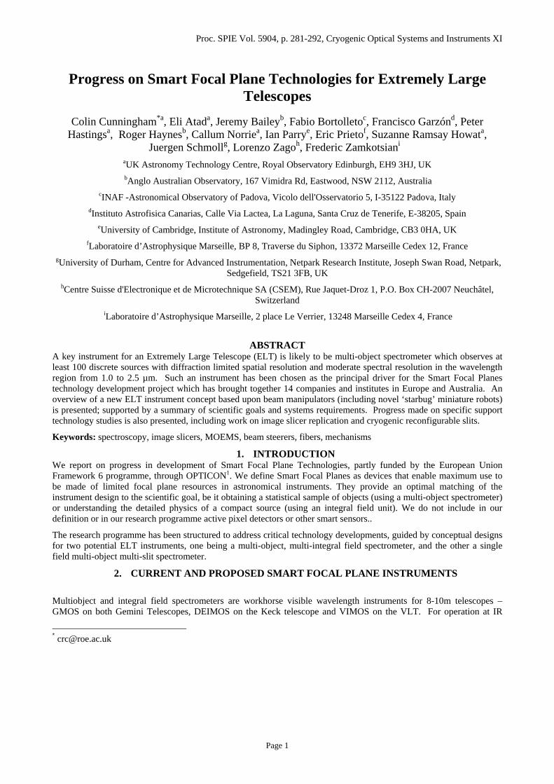
wavelengths of up to 2.5 microns and beyond, it is essential to cool the spectrometer slit masks, or feed image slicing Integral Field units using programmable pick-off optics. Current MOS instruments working at IR wavelengths use separate Dewar modules to enable change of slit masks without thermally cycling the whole instrument. More rapid configuration of cryogenic slit masks entails the use of complex cryogenic mechanisms, and will be provided in the EMIR instrument being built for the GTC. The GIRMOS concept for Gemini used a combination of deployable optical pick-off arms feeding image slicing integral field units to replace configurable slits or exchangeable sit masks. This pick-off arm concept (Figure 1) has now evolved into the fully-funded KMOS instrument for ESO-VLT (Sharples2).
Figure 1 KMOS Pick-off arms
The aim of the OPTICON Smart Focal Planes project is to develop technologies which will enable MOS and IFU spectroscopy to be carried out at IR wavelengths on current and next generation telescopes. In order to ensure that technology we develop has maximum impact into the era of Extremely Large Telescopes, we have developed concepts for instruments for ELTs based on the two principal options: reconfigurable slits and deployable pick-offs. These concepts have been used to develop challenging specifications to ensure the technology development is sufficiently constrained to be realistic and useable at the same time as allowing sufficient latitude to encourage innovation. As a further constraint, we chose to adopt the interface to the OWL telescope design.
3. ELT DRIVERS FOR SFP TECHNOLOGY
Previously we have made the case for novel technologies to be developed to enable ELTs to be used to make maximum use of the telescope focal plane at reasonable cost (Cunningham3). The recently released Science Case for a European 50 -100m telescope shows the dramatic possibilities which multi object spectrometers on ELTs will open up, but also emphasises the challenging technical specifications expected.
The methodology we have used to develop SFP technology is:
• Use the Science Case to develop specifications for nominal Instruments for multiobject spectroscopy • Evaluate the critical technologies needed to meet such a specification • Survey current technology for suitability • Innovate where there are gaps • Develop and prototype novel and existing technology: feedback lessons-learned and limitations into a more
practical instrument specification • Bring technologies together in a laboratory demonstrator
The programme is currently at the technology prototyping level. A very important outcome of the programme is to develop capability within Europe and our partners in Australia by building a strong working team across seven nations – a key reason for the European Union funding such a programme through Framework 6.
Page 2
3.1 ELT instruments as technology drivers: Smart Integral Field Multi Object Spectrometer As a framework for the Smart Focal Planes developments, we have selected instruments that form part of the EU-supported Framework 6 Design Study for a European ELT (Russell4). These instrument concepts have been selected to meet the draft science requirements for an ELT, based on the science case, and also to explore the impact of the likely instrumentation suite on the telescope design. The first instrument we studied is based on the Multi-Object Multi-field Spectrometer and Imager (MOMSI). We expect the MOMSI concept to evolve during the Design Study, so to avoid confusion we designate the concept we use to set our technology requirements in this programme SMART-MOMSI.
3.1.1 Instrument concept and science requirements. An important breakthrough for a 100-m ELT telescope will be to measure the Herzsprung-Russell diagrams for galaxies in the Virgo cluster. With a 100-m diffraction limited telescope, modelling suggests that individual stars will be resolved at 20Megaparsecs, the distance of Virgo. Obtaining an accurate age and chemical composition for these stars at different locations in the galaxy will reveal its star formation history. The formation and evolution of galaxies and the impact of environment on that process is another key science case for an ELT. Targetting deep, high redshift fields such as the Hubble Ultra-Deep Field, spectroscopy of the individual galaxies will explore their physical properties, such as star formation rate and dynamics, as a function of redshift. Both of these goals require near-infrared spectroscopy at moderately high spectral resolving power (R~4000) to access the principal diagnostic lines (e.g Halpha, Hbeta, O[III]). We have developed the requirements for the MOMSI instrument based on this science case to provide a set of meaningful and stretching requirements for the technology developments, taking as starting point the predicted performance of an f6 100-m telescope with diffraction limited performance (50% Strehl at K over a 2arcmin field) provided by a multi-conjugate adaptive optics system.
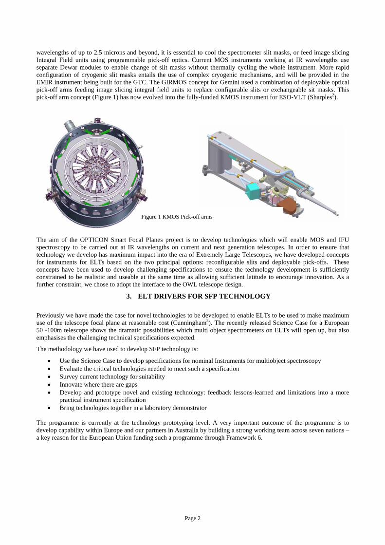
3.1.2 SMART-MOMSI Instrument Concept The imaging mode from MOMSI has not been developed any further within the Smart Focal Planes scope of work, as the spectroscopic mode already offers sufficient challenges to explore the SFP technologies. In spectroscopic mode, the science requirements call for a minimum of 100 fields of 100mas x 100mas in size to be selected from a field of 2arcminute diameter. For an f-6 100m telescope, the plate scale is 2.92mm arcsec-1. The physical diameter of the 2arcmin field is therefore 350mm and the individual fields are 300µm square. The core wavelength range for the instrument is 0.8-2.5µm, leading to an operating temperature for the cryostat of 130K. The field is sampled with spatial resolution matched to the diffraction limit at 2µm, requiring 2.5mas sampling. The initial concept for the integral field unit is based on image slicing, and so the requirement is for 40slices of 2.5mas width and 100mas length.
Relating the integral field unit requirements to physical sizes for the image slicer requires the development of a concept for the MOMSI spectrometer module, as this is not directly constrained by the science requirements. Conceptual designs for multi-integral field spectrometers have varied in the approach taken in coupling the IFU output to the spectrometer. The ESO-VLT KMOS instrument has 24 integral field units, with the output from eight forming the pseudo-slit input to a spectrometer. For the MUSE instrument, an integral field unit which provides contiguous coverage over a 1arcminute field is made up from 24 IFUs coupled to 24 spectrographs (Hainault5). It is the latter
Page 3
approach that we have taken for MOMSI, with a 1:1 coupling from each IFU to a simple spectrometer.
A 3-mirror optical concept was developed based on a diffraction limited instrument on a 100m OWL telescope and 100 pick-offs, which may be the maximum practical number. The optical concept is based on 3 mirrors feeding each pick-off field into an image slicer which in turn feeds each modular spectrometer. The first mirror is a ‘Starbug’ (McGrath6) which can be placed anywhere on the focal plane either by using a self-propelled robot or a pick-and place mechanism. This carries an optical element which is either a tilted spherical mirror or a lens and a flat mirror. In either case, the optics perform the same task – to collimate the light from the focal plane and to direct it towards the first element of the receiving optics The bug carries a concave spherical mirror steerable in two dimensions across the focal plane. The bug is held in position on the steel surface below the focal plane by permanent magnetism.
Each 100mas field of the f/6 beam coming from the OWL telescope is collimated producing a 4 mm diameter beam and an image of the aperture 25 mm from the pole of the spherical mirror on the bug. This aperture image is arranged to be at the radius of curvature of mirror AM1. When the bug is moved across the focal plane, the aperture image moves with it but is kept at the radius of curvature of mirror AM1 by displacement of the position of that mirror along the optical axis.
The mirror AM1 is a concave toroidal mirror and must be steerable in two axes by up to 5 and 20 degrees to follow the motions of the bug, as well as the lateral adjustment of 12mm. It must also be deformable to change its radius of curvature from around 2.2m by up to 5mm AM1 has 2 functions: it produces an image of the aperture on mirror AM2 and produce a f/300 convergent beam required for the slicers (300 µm wide slices). The mirror AM2 is flat, but is also deformable to correct at least 4 Zernike terms in coma and astigmatism. Preliminary optical analysis shows that this design can give diffraction limited performance over the 2 arcmin field.
3.2 ELT instruments as technology drivers: Smart-MOS The second instrument concept we have developed to derive technology specifications aims to fill the ample scientific niche for a large field of view NIR MOS instrument, seeing-limited or using ground layer adaptive optics, and is based on the WFSPEC instrument in the European FP6 Design Study. To differentiate the concept from that which will evolve in the Design Study, we call it SMART-MOS. This concept has not been taken as far as SMART-MOMSI, and it is only driving technology development for one aspect: reconfigurable slit mechanisms. The science case for a SMART–MOS instrument points to a large FOV of up to 4 arcmin. However, initial optical design studies suggest that it would be very hard to obtain field of over one arcmin for the OWL design. In order to cover a larger FOV multiple instruments could be employed, or a variation of the MOMSI concept adapted to this seeing limited or low order Adaptive Optics situation. It is very desirable that it is fully reconfigurable in a short time to allow for efficient operation of the instrument. This suggests that custom manufactured replaceable slit masks will not be practical in a cryogenic instrument. The two options we have considered are mechanically reconfigurable multi-slit masks and programmable micro-shutters or mirrors based on MOEMS devices. This specification results in the need for an exceedingly fast camera, of the order of f/1 (for a 2k detector with 18 micron pixels).
4. TECHNOLOGY DEVELOPMENTS IN THE OPTICON PROGRAMME
Development of these two instrument concepts has led us to the conclusion that the critical technologies to be developed to enable an IR MOS instrument for an ELT to be built at reasonable cost are:
• Beam steering devices: active robotic pick-offs, passive pick-off positioned using a pick and place mechanism, or fibre-based devices
• Steerable deformable mirrors • Linear focus mechanisms • High precision image slicers
Page 4
• Fibre IFUs • Slit mechanisms: macro and micro
All must be capable of economic production in quantities of around 100, and must operate reliably at cryogenic temperatures. Many of the challenges associated with such requirements are common across the devices, so we have also engaged in a parallel enabling technology study to review tribology, actuation, position sensing and 3D metrology at cryogenic temperatures.
4.1 Beam Manipulators
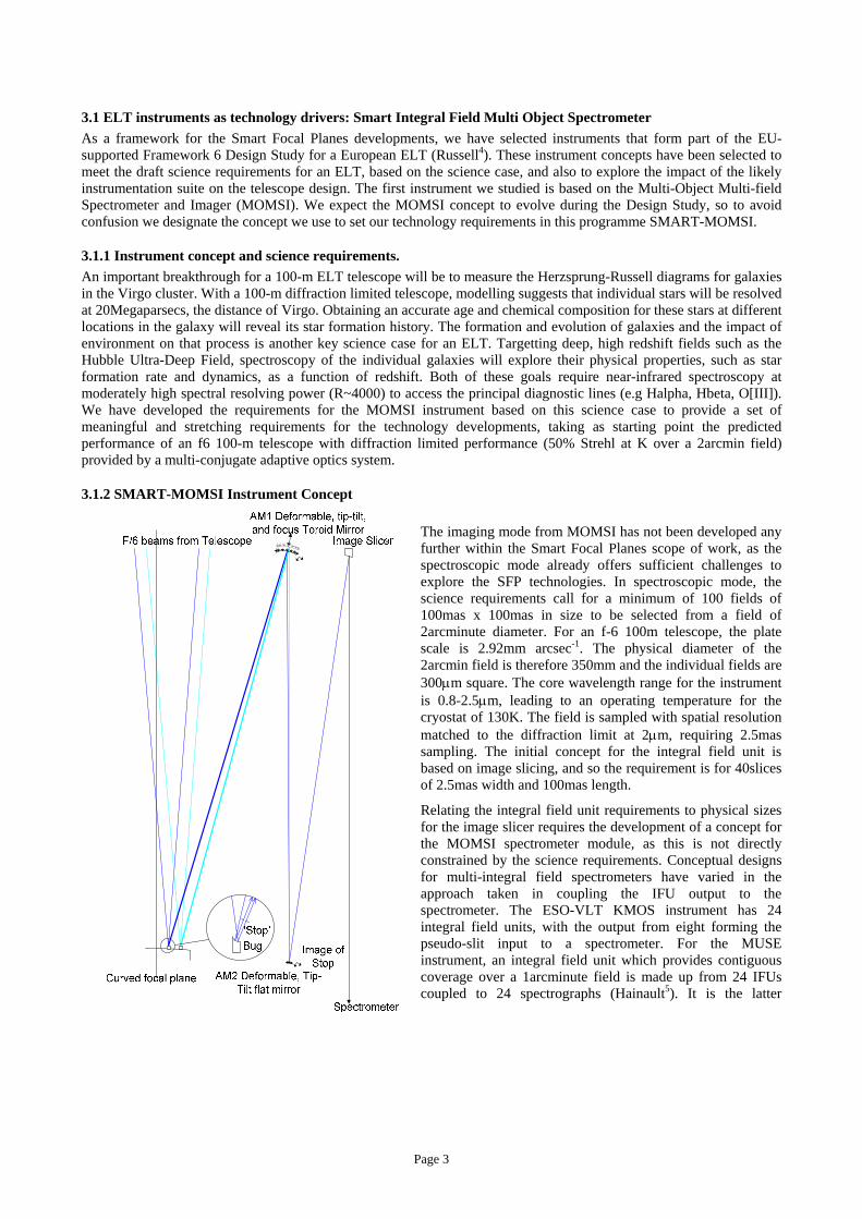
4.1.1 Starbugs First described as recently as 2004 (McGrath6), Starbug is a new concept for a robotic system positioning payloads such as pickoff optics, fibres or deployable IFUs on telescope focal surfaces. An extension of concepts used in existing fibre positioning systems, Starbug retains the advantages of each type of existing positioner, while eliminating many of the disadvantages. It employs micro-robotic actuators to independently and simultaneously position multiple small payloads accurately on an arbitrarily large field plate, and offers a cost-effective and multiply-redundant design for payload positioning systems suitable for use at telescope foci. Operation in cryogenic environments, micron positioning resolution, simultaneous movement of arbitrary numbers of payloads and the removal of many movement constraints are some of the advantages offered. MOMSI imposes particularly challenging focal surface positioning requirements that well match a Starbug implementation. Figure 2 Starbug
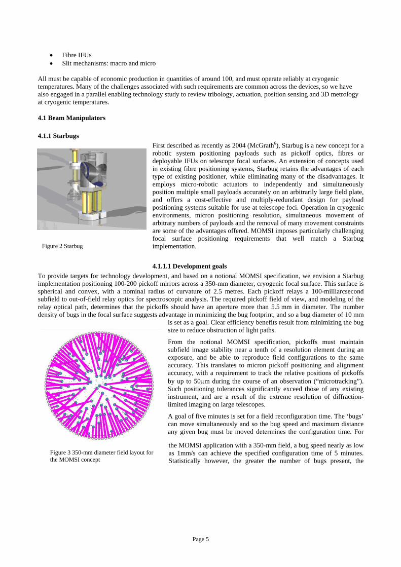
4.1.1.1 Development goals To provide targets for technology development, and based on a notional MOMSI specification, we envision a Starbug implementation positioning 100-200 pickoff mirrors across a 350-mm diameter, cryogenic focal surface. This surface is spherical and convex, with a nominal radius of curvature of 2.5 metres. Each pickoff relays a 100-milliarcsecond subfield to out-of-field relay optics for spectroscopic analysis. The required pickoff field of view, and modeling of the relay optical path, determines that the pickoffs should have an aperture more than 5.5 mm in diameter. The number density of bugs in the focal surface suggests advantage in minimizing the bug footprint, and so a bug diameter of 10 mm
is set as a goal. Clear efficiency benefits result from minimizing the bug size to reduce obstruction of light paths.
From the notional MOMSI specification, pickoffs must maintain subfield image stability near a tenth of a resolution element during an exposure, and be able to reproduce field configurations to the same accuracy. This translates to micron pickoff positioning and alignment accuracy, with a requirement to track the relative positions of pickoffs by up to 50µm during the course of an observation (“microtracking”). Such positioning tolerances significantly exceed those of any existing instrument, and are a result of the extreme resolution of diffraction-limited imaging on large telescopes.
A goal of five minutes is set for a field reconfiguration time. The ‘bugs’ can move simultaneously and so the bug speed and maximum distance any given bug must be moved determines the configuration time. For
the MOMSI application with a 350-mm field, a bug speed nearly as low as 1mm/s can achieve the specified configuration time of 5 minutes. Statistically however, the greater the number of bugs present, the
Figure 3 350-mm diameter field layout for the MOMSI concept
Page 5
shorter the expected configuration time because no bug needs to move the full diameter of the plate – if 100 bugs are uniformly distributed, no part of the plate is more than ~15mm from a bug. It is likely that modeling will show significantly lower bug speeds will in general meet the goal.
At the outset of this work, the only demonstrated prototype Starbug actuator did not possess sufficient axes of motion (no rotation), or sufficient load-bearing capacity. No performance optimization had been undertaken, it had not been demonstrated in cryogenic conditions, nor operated under closed loop control. Its 0.5mm/s speed of motion was marginal for the MOMSI configuration time specification.
4.1.1.2 Metrology for bug characterisation Although various metrology schemes may be imagined to provide position for the bugs, we chose a focal plane imaging arrangement based on that used in other AAO fibre positioners. An inexpensive frame-rate video camera images the field, viewing reference marks on the bug, and software locates its position and orientation. Various image scales were used for various bug characterization tests, however distance measurements of 270 separate bug movements were used to derive a centroiding standard deviation of 0.01 pixels. At the finest plate scale used, this gave a 3-sigma measurement accuracy of 1.5µm over a 40mm field, and was used to characterize bug minimum step size. No absolute calibration for this system was undertaken, although in principle it would be straightforward to empirically derive a calibrated distortion map for a fixed camera/focal surface geometry. An extended, high resolution extension of this arrangement may be suitable for a Starbug instrument implementation.
4.1.1.3 Actuator development Given the immaturity of technology meeting the Starbug positioning, cryogenic and load requirements, we developed and experimented with a variety of microrobotic actuators, based on the AAO’s experience with FMOS-Echidna (Gillingham7). Four different families of actuator were trialed; inertial stick-slip, inchworm, active plate and resonant drives. Several designs of bug have been tested. One exceeded many of the design goals, achieving controllable rotation and x-y translation at speeds greater than 5mm/s, with a diameter of only 6mm. Minimum step size demonstrated for this particular bug was less than 2µm, approaching the submicron goal. Actuators of other technologies tested achieved step sizes of ~0.1µm, as measured with an inductance probe.
4.1.1.4 Automated bug control With a metrology system providing position feedback, a model of the actuator movement response, and computer control of the driving waveform, closed loop control may be implemented to drive the bug from a starting point to a desired destination, with accuracy limited by the minimum bug step size and metrology. This was demonstrated to operate a single bug under closed loop control with a loop cycle time of under 100ms, and a destination arrival accuracy near 10µm, commensurate with the plate scale of the imaging metrology system used for this test.
4.1.1.5 Cryogenic operation Bugs were cooled in a test dewar to temperatures as low as -100°C for vacuum and low temperature performance measurement, demonstrating operation to temperatures low enough for K-band observation.
Table 1. Goal and achieved performance parameters for one of the bug designs under development. Other bug designs have exceeded stated performance in specific parameters, however this design meets or approaches goals in many parameters.
Parameter Goal Achieved Size Footprint <10mm diameter Footprint 6mm diameter Translation Arbitrary x-y direction Arbitrary x-y direction Rotation Rotation in both directions Rotation in both directions Speed of motion >1mm/s 5mm/s (at room temperature) Incremental step size <1µm 2µm
Page 6
Low temperature operation <-100ºC -100ºC, with reduced step size and speed of motion
Direction of gravity vector Arbitrary Arbitrary, with some variation in achieved speed
Control Closed-loop with position feedback
Closed loop with position feedback
4.1.2 Planetary Positioner Unit for a Smart Focal Plane As an alternative solution for the SMART-MOMSI concept, we are developing a robotic positioner working at cryogenic temperatures to arrange passive pick-off mirrors (PMs) on the focal plane. This option will be particularly useful if technical or cost difficulties occur in developing wireless Starbugs. Compared with Starbugs which can be rearranged in a parallel fashion, this option has to work sequentially. While the time taken to position each mirror can be relatively short, it will still be necessary to arrange that one pattern of PMs is set up while another is observing if excessive telescope time is not to be wasted. To allow this to happen, the PMs are placed on both sides of a focal plate which can be turned over so that as one set of PMs is illuminated from the sky the other set is being re-configured ready for the next observation., in the same way fibre positioning robots such as 2df operate. An additional requirement is to be able to place the PMs on a surface which matches the curvature of the telescope focal plane. The focal plate has an illuminated diameter of 350mm and a radius of curvature (convex) of 2.5 m.
Each PMs is moved by being gripped, lifted clear of the other PMs, moved to a new location, given a new orientation, lowered in place and released. The robotic positioner unit consists of the focal plate and its tumble mechanism (UKATC/Astron), a gripper assembly (CSEM), a positioner robot (UKATC/Astron) and a target acquisition and metrology system (AAO). The focal plate unit is a relatively straightforward cryomechanism which turns the plate through ± 90 degrees, locks it in place during an observation and provides a suitable cooling path to remove the heat falling on it from the window of the vacuum vessel which will enclose the whole system. The gripper unit provides a means of closing two jaws on to the PM with a controlled force and lifting the PM ~25mm to clear the others. It has a through hole along its axis to allow an acquisition camera to check that the jaws and the PM are aligned accurately before the PM is gripped.
The positioner robot is of a new design (UK Patent applied for, number 0513339.2) similar in its geometry to a swing-arm profilometer which is used for measuring aspheric optical surfaces. A large turntable rotates about an axis which passes through the centre of curvature of the focal plate. It carries an arm which is pivoted about an axis which also passes through the centre of curvature of the focal plate. The movement of this arm enables the gripper to be swung from the middle of the focal plate to just beyond its edge. The gripper assembly is carried on a small rotary stage which is used to align the gripper jaws with the PM before it is grasped. The geometry of this system automatically ensures that the lift-and-lower motion of the gripper assembly is always perpendicular to the surface of the focal plate irrespective of the position of the gripper on the plate. This minimises any tendency for the PM to squirm as it is pushed into contact with the focal plate. When the gripper is swung beyond the edge of the focal plate, the plate can be turned over (tumbled) to deploy the new pattern of PMs.
Figure 4: Schematic of the Planetary Positioner Robot tumble
ihousing
Figure 4 shows the main mechanisms of the positioner robot. A principal feature of the design is that all the major positioning movements of the gripper are rotary. This allows them to be balanced easily which minimises the changes in gravitational deflection of the unit
swing arm
gripper lift and lower focal
plate
turntable bearing
Page 7
as the telescope tracks across the sky.
The unit is also compact radially which makes packaging it into an instrument much easier. The end view on the right of shows that much of the focal plate is clearly visible as the positioner is working. It is expected that the metrology system for confirming the exact position of all the PMs before the focal plate is tumbled will be similar to that described for the Starbug devices.
A concept for a gripper system is being developed, with the pinch function based on gripper design already developed for the semiconductor industry by CSEM but with an optical through-hole along the central axis to enable accurate metrology during PM placement.
4.1.3 Active Mirrors The concept is derived from several years experience at LAM in development of metal active mirrors. The idea is to deform a thin optical surface using 4 piezoelectric actuators. This deformation will adapt the curvature radius of the
surface in X and Y direction independently. For the MOMSI design, we need a mirror diameter of 200 mm, with a toroidal surface of nominal curvature radius of 4000 mm, adjustable to plus or minus 400 mm in each axis of the toroid. LAM have shown over several years that a general solution is to use four actuators and one fixed point, which enables the mirror be deformed to a specific shape and have a smooth deformation without high frequency deformation.
Finite element analysis linked directly to optical ray-tracing (ZEMAX) predicts that it is possible to maintain diffraction limited performance by actuating the surface to control the deformation of this mirror as it tracks the PM or Starbug across the field.
Figure 5: principle of actuation generating the deformation of the steering mirror
4.2 Image slicer micro-optics for ELTs The SMART-MOMSI virtual instrument requires integral field units (IFUs) to feed the spectrometers to enable 3D spectroscopy of 100 mas fields. For diffraction limited sampling the slicing mirror size has to be extraordinary small, down to 0.1 mm slice width, to minimise the mass and space taken by fore-optics. Taking into account that large numbers of deployable IFUs are necessary to exploit the large focal planes of an ELT, the number of single IFUs can reach or exceed one hundred, stressing the volume and mass
aspect by at least two orders of magnitude.
The most efficient IFUs for the near infrared regime are designed with reflective image slicing mirrors rather than optical fibers (Allington-Smith8). Apart from the ease of using them under cryogenic environment, there are no instabilities as observed in optical fibers, and no loss of etendue. Image slicers can be built up from separate optical surfaces (Todd9), but monolithic items make alignment and rigidity issues less troublesome. This applies particularly to the small scale of components to be used in ELTs in diffraction limited cases. The most common method of production for facetted free-form optics is diamond machining. However, diamond-machining of large amounts of similar micro-optical components is time consuming and expensive. Furthermore due to tool wear and material inhomogeneities the result may not be as reproducible as replicated devices, using a single master piece as a preform. We are testing replication techniques, using test masters diamond-machined by LFM, Bremen. The experiments have been done by Reflex (Prague, Czech Republic) and Media Lario (Merate, Italy).
In the slicer replication approach the technical limits for small mirror fabrication have been explored, taking into account special needs in terms of release angle and chamfer sizes, which are critical to determine the best fill factor
Page 8
which can be achieved on very small slicing mirror arrays. The experiments show that for a 0.1 mm wide slicer element a fill factor of about 0.9 is easily met or exceeded. Problems being investigated are shape deviation and the duration of a standard replication process, being between one and two weeks for a single replica. We are testing a double replication process with a much faster intermediate resin casting step. The next steps will be to determine the lifetime of a master mandrel used to make intermediate resin mandrels, and the replication of realistic test pieces: the pupil and slicer mirrors derived from the existing GNIRS IFU (Allington-Smith8). Further studies will compare different production methods and strategies of multi-alignment and mass-metrology.
4.3 Technology for reconfigurable slit masks The Smart-MOS instrument concept requires a programmable slit mask operating at cryogenic temperatures. A concept developed for NIRSPEC on JWST uses edges of opposite bars to create variable width slits as shown below (Crampton10). The mask can provide in its field of view many slits as pairs of bars, and offers versatility for slit-width adjustment and a simple implementation of an imaging mode.
Figure 6: A functional model of reconfigurable slit array realised by CSEM for the JWST. The 130x130 mm field is divided into stripes. Within each stripe a variable slit is obtained by positioning two bars each terminated with a sharp edge
Figure 7: The CSEM prototype mechanism
A large MOS will have large fields and need masks allowing a large number of slits: for instance EMIR is planning a field of 300x300 mm with 50 slits. The practical and cost-effective realization of these complex active mechanisms requires solving issues of manufacturing cost and control of cryogenic actuators.
Page 9
The bars are to be thin and relatively long (~700 mm), and must remain straight following cycling to cryogenic temperatures. Currently the manufacturing cost of bars made for the JWST prototype (where bars are only 300 mm long) exceeds €1k per unit. To make this technique practical for large masks, cheaper manufacturing methods must be sought, which nonetheless maintain the good properties of the expensive prototypes. On the basis of the bar design used in the prototype (which is machined by EDM) alternative designs have been explored, which are both lighter and promise a reduction of manufacturing cost
4.4 Micro-Opto-Electro-Mechanical Systems (MOEMS) An alternative to the slit mechanism shown above is the use of MOEMS devices such as micro-mirror arrays (MMAs) or micro-shutter arrays (MSAs), allowing remote control of the multi-slit configuration in real time. MOEMS are based on mature silicon micro-electronics processes and their main advantages are their compactness, scalability, and specific task customization using elementary building blocks. While the development of this technology is expensive, these systems are easily replicable and the price of the components is decreasing dramatically when their production volume is increased. The typical size of these micro-elements is around 100µm, and MMAs are designed for generating reflecting slits, while MSAs generate transmissive slits. MSA has been selected to be the multi-slit device for NIRSpec and is under development at the NASA's Goddard Space Flight Center. They use a combination of magnetic effect for shutter opening, and electrostatic effect for shutter latching in the open position (Moseley11).
In Laboratoire d’Astrophysique de Marseille, we have developed over several years different tools for the modelling and the characterization of these MEMS-based slit masks. Our models, based on Fourier theory (Figure 8), address two key parameters for the MOS performance: contrast and spectral photometric variation (SPV). The SPV requirement is generally < 10%, but as SPV is strongly dependent on the object position and wavelength, the required value cannot be reached. We have proposed a dithering strategy able to solve this problem (Zamkotsian12).
Field (MSA plane)
Spectrograph Pupil
Detector Plane
JWST telescope
Figure 8: Spectrograph model including the telescope shape and wavefront errors, the MOEMS-based slit mask, the limited pupil in the spectrograph (grating), the optics aberrations, and the pixelisation on the detector.
We have also developed a characterization bench to measure these parameters. Preliminary contrast measurement has been carried out on the MMA fabricated by Texas Instrument, in order to simulate the actual MOEMS device for NIRSpec. Contrasts of around 500 have been measured for an ON-OFF angle of 10°; this value is exceeding 3000 when the ON-OFF angle is 20°. Effects of object position on the micro-mirrors have been revealed (Zamkotsian, 2003). Additional parameters such as the size of the source, the wavelength, and the input and output pupil size are also analysed. We are simulating the operation of a multi-object spectrograph with our multi-object field of view with several sources. By using attenuation filters, we can set the magnitude difference between the studied object and the spoiling source(s). First results show the impact of interfering sources even when they are located at several times the diameter of the sources (PSF and diffraction effects). Measurement on micro-shutters with the adaptation of the bench for these devices in transmission is possible. In the future, cryogenic tests will be performed.
We have engaged in a collaboration with the Institut de Micro-Technologies (IMT) of University of Neuchatel (Switzerland) in order to get a first demonstrator of a European MOEMS-based slit mask. Micro-mirrors have been
Page 10
selected and a .design is under investigation in terms of performances and feasibility. Our simulations and measurements show that it is best to project one astronomical element on each micro-mirror, significantly reducing the major sources of scattered light. To reach a contrast value > 3000, we set the deflection angle at 20°. The mirrors surfaces must be flat and the gaps between mirrors minimized: a fill factor > 90% is foreseen. In order to fit with the plate scale of 8m-class telescopes as well as future ELTs, micro-element size must be at least 100 µm x 200 µm. Driving voltages of less than 100V enable the use of conventional drive electronics. Additional requirements are reliability and cryo actuation capabilities. Based on these requirements, we have designed with IMT an original micro-mirror array to be built with silicon materials using the bulk micromachining process. First elements are scheduled for the beginning of 2006.
4.5 Optical Fibre Technologies Fibre-based MOS and IFU at visible wavelengths have been very scientifically productive in recent years. In this programme we are investigating how they compare with the other Smart Focal Plane technologies described here, in particular when used at longer wavelengths and in cryogenic instruments.
Some of the advantages of fibre systems are versatility in selecting targets and dealing with convoluted light-paths, especially when locating bulky spectrometers remote from the telescope focal plane and in gravity invariant locations. Disadvantages include focal ratio degradation (FRD) which reduces the effective throughput of the system, and absorption, particularly at longer wavelengths.
One aspect of fibre systems which may be easier for ELT instruments where the science case does not require us to reach the diffraction limit is that the microlens arrays needed to couple the fibres to the telescope focal plane may be replaced with larger lens combinations, with consequent improved FRD (Lee13)
Current instruments use silica fibres which work well between 0.3 and 1.1 microns, and can be used in a cryogenic environment. Operating in K-band (2-2.5 microns) and beyond requires the use of materials such as fluorides or chalcogonides. We will evaluate these by making three deployable IFUs using ultra-low-OH silica, zirconium fluoride and chalcogenide fibres, and testing at low temperatures both optically and mechanically.
4.5.1 A NIR Fibre-based multi-IFU deployment concept One aspect common to pick-off arms (KMOS), magnetically held fibres (2dF) and Starbugs (MOMSI) is that the optical path is folded up or across from the focal plane, placing severe constraints on the optical layout and space envelope. Fibre plug plates are better but they are not robotic and therefore labour-intensive. The concept presented here combines the best of both worlds offering a robotic system with minimal configuration constraints. It consists of a set of deployable IFUs which can be robotically positioned on a glass surface near the telescope focal plane. The IFUs are held on to the glass plate using gas pressure. This concept was not viable in the past because the small fibre ferrules used for MOS did not have sufficient area to provide a good holding force. However, as we push to larger telescopes (8m and ELTs) and we replace single fibres with IFUs, the obtainable holding force becomes more than sufficient.
5. FUTURE RESEARCH IN OPTICON The Opticon Joint Research Activity has enabled us to make significant progress in developing many of the technologies needed for the most challenging multi-object spectrometers for future Extremely Large Telescope. The next step is to decide on the priorities for the next phase of development, based on a trade-off study and evaluation of where we can make the most innovation for maximum scientific benefit. We intend to build working prototypes over the next year for:
We will then propose to build a prototype instrument based on these technologies. Of course, the ultimate aim is to build an ambitious instrument similar to the MOMSI concept for an ELT
Page 11
6. ACKNOWLEDGEMENTS
We thank the many people in the partner organisations that have made contributions to this programme. OPTICON has received research funding from the European Community's Sixth Framework Programme under contract number RII3-CT-001566. Further support is received from member organisitions. Starbugs have additional support from the Innovation Access Programme – International Science and Technology - under the Australian Government innovation statement, Backing Australia’s Ability.
Hofmann, R; Ivison, R.J.; Saglia, R.; Thatte, N.A. “KMOS: an infrared multiple-object integral field spectrograph for the ESO VLT” Ground-based Instrumentation for Astronomy. Ed. Moorwood and Masanori. Proc SPIE, 5492, 1179-1186 (2004)
3. Cunningham, C.R.; Ramsay-Howat, S.K.; Garzón, F; Parry, I.R.; Prieto, E; Robertson, D.J.; Zamkotsian, F. “Smart focal plane technologies for ELT instruments” Second Backaskog Workshop on Extremely Large Telescopes Ed: Ardeberg and Andersen Proc SPIE 5382 718-726 (2004)
4. Russell, A P.; Monnet, G; Quirrenbach, A; Bacon, R; Redfern, M; Andersen, T; Ardeberg, A; Atad-Ettedgui, E; Hawarden, T.G., “Instruments for a European Extremely Large Telescope: the challenges of designing instruments for 30-100m telescopes”, Ground-based Instrumentation for Astronomy. Ed. A.F.M. Moorwood and I Masanori.Proc. SPIE, 5492, 1796-1809, (2004)
5. Henault,F; Bacon,R; Dekker, H; Delabre,B; Djidel,S; Dubois, J-P; Hubin, N; Lantz,N.B; Lau,W; Le Louarn,M; Lewis,I.J; Lizon,J-L; Lynn,J; Pasquini,L; Reiss,R , Roth,M.M; “MUSE optomechanical design and performance” Ground-based Instrumentation for Astronomy, Ed. Moorwood, A and Masanori, I, Proc. SPIE 5492, 909-920 (2004)
6. McGrath, A and Moore, A “Starbug: enabling the smart focal plane”, Ground-based Instrumentation for Astronomy, Ed. Moorwood, A and Masanori, I, Proc. SPIE 5495, 600-610 (2004)
7. Gillingham, P.R.; Moore, A.M.; Akiyama, M; Brzeski, J; Correll, D; Dawson, J; Farrell, T J.; Frost, G; Griesbach, J.S.; Haynes, R; Jones, D; Miziarski, S; Muller, R; Smedley, S; Smith, G; Waller, L.G.; Noakes, K; Arridge, C; “The Fiber Multi-object Spectrograph (FMOS) Project: the Anglo-Australian Observatory role”, Instrument Design and Performance for Optical/Infrared Ground-based Telescopes, ed. M. Iye & A. Moorwood, Proc. SPIE 4841, 985-996 (2003)
8. Allington-Smith, J.R.; Dubbeldam, C. M.; Content, R; Dunlop, C. J.; Robertson, D.J.; Elias, J; Rodgers, B; Turner, J.E. ”Integral field spectroscopy with the Gemini Near-Infrared Spectrograph” Ground-based Instrumentation for Astronomy, Ed. Moorwood, A and Masanori, I, Proc. SPIE,5492, 701-710 (2004)
9. Todd, S.P; Wells, M; Ramsay Howat, S.K; Hastings, P.R. “Cryogenic image slicing IFU for UKIRT: manufacture, alignment, laboratory testing, and data reduction” Specialized Optical Developments in Astronomy Ed Atad-Ettedgui, E; D'Odorico, S. Proc SPIE, 4842, 151-161 (2003).
10. Crampton, D; et al “Canadian Near-IR MOS/IFS Concept for NGST” Next Generation Space Telescope Science and Technology, Ed Smith, E and Long, K ASP Conference Series, 207, 149 (2000).
11. Moseley, S. H.; Blumenstock, K. A.; Ewin, A.; Franz, D. E.; Hein, J.; Hu, R.; Kotecki, C.; Kutyrev, A. S.; Laughlin, J.; Li, M. J.; Lynch, B.; Miles, A.; Mott, D. B.; Rapchun, D. A.; Schwinger, D. S.; Silverberg, R.; Smith, W.; Wesenberg, R. P.; Zincke, C.; Zheng, Y. “Microshutter arrays for JWST - programmable field masks” Bulletin of the American Astronomical Society, 34, 1240 (2002)
12. Zamkotsian, F; Dohlen K, “Performance modeling of JWST near-infrared multi-object spectrograph” Optical, Infrared, and Millimeter Space Telescopes Ed Mather, J, Proc SPIE 5487, 635-644 (2004)
13. Lee, D; Haynes, R; Ren, D; Allington-Smith, J, “Characterization of Lenslet Arrays for Astronomical Spectroscopy” Publications of the Astronomical Society of the Pacific, 113, (789), 1406-1419 (2001)