·I I I ·1 I I I ·I I I I I PROGRESS REPORT FOR ]OWA HIGHWAY RESEARCH BOARD PROJECT HR-178 DYNAMIC PAVEMENT DEFLECTION MEASUREMENTS by Vernon J. Marks May, 1977 Iowa Department of Transportation Highway Division Off ice of Materials Ames, Iowa 50010 515+296-1447
Transcript
·I I I ·1
I I
I ·I I I I I
PROGRESS REPORT FOR
]OWA HIGHWAY RESEARCH BOARD PROJECT HR-178
DYNAMIC PAVEMENT DEFLECTION MEASUREMENTS
by Vernon J. Marks
May, 1977
Iowa Department of Transportation Highway Division
Off ice of Materials Ames, Iowa 50010
515+296-1447
I. I I I I I I I I I I I I I I I I I I
TABLE OF CONTENTS
Introduction
Changes in Pavement Deflection Operation . Using the Road Rater
Road Rater Training
Correlation of the Road Rater and Benkelman Beam
Correlation of Road Rater Deflection and AASHTO Structural Numbers
Determination of Seasonal Deflection Variation of Flexible Pavement
Determination of Increased Structural Capability Due to Resurfacing
Road Rater Equipment Problems
Deflection variation Caused by Pavement Temperature
Summary of 1976 Road Rater Deflection Data
Appendix A - Method of Test for Determining Pavement Deflection Using the Road Rater
Appendix B - Method of Test for Determining Pavement Deflection Using the Benkelman Beam
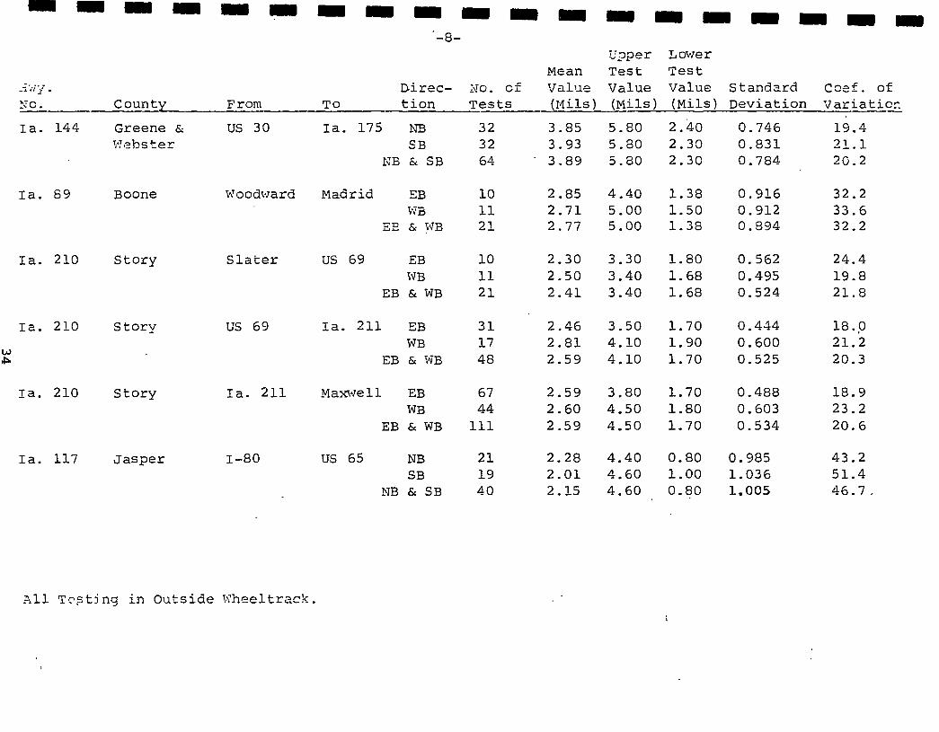
Appendix c - Summary of the 1976 Road Rater Pavement Deflection Data
1
5
6
7
10
12
13
13
15
15
16
21
26
I I I I I I I I I I I I I I I I I I I
DYNAMIC PAVEMENT DEFLECTION MEASUREMENTS
INTRODUCTION
In October, 1975, when project HR-178, "Dynamic Pavement
Deflection Measurement" was approved, there were two commercially
available systems that were considered. They were the Dynaflect
and the Road Rater. After obtaining information from the
manufacturers and other state highway departments, the advantages
of each were considered and the decision was to purchase a Road
Rater. The reasons for this decision are given in a November 11,
1975 progress report.
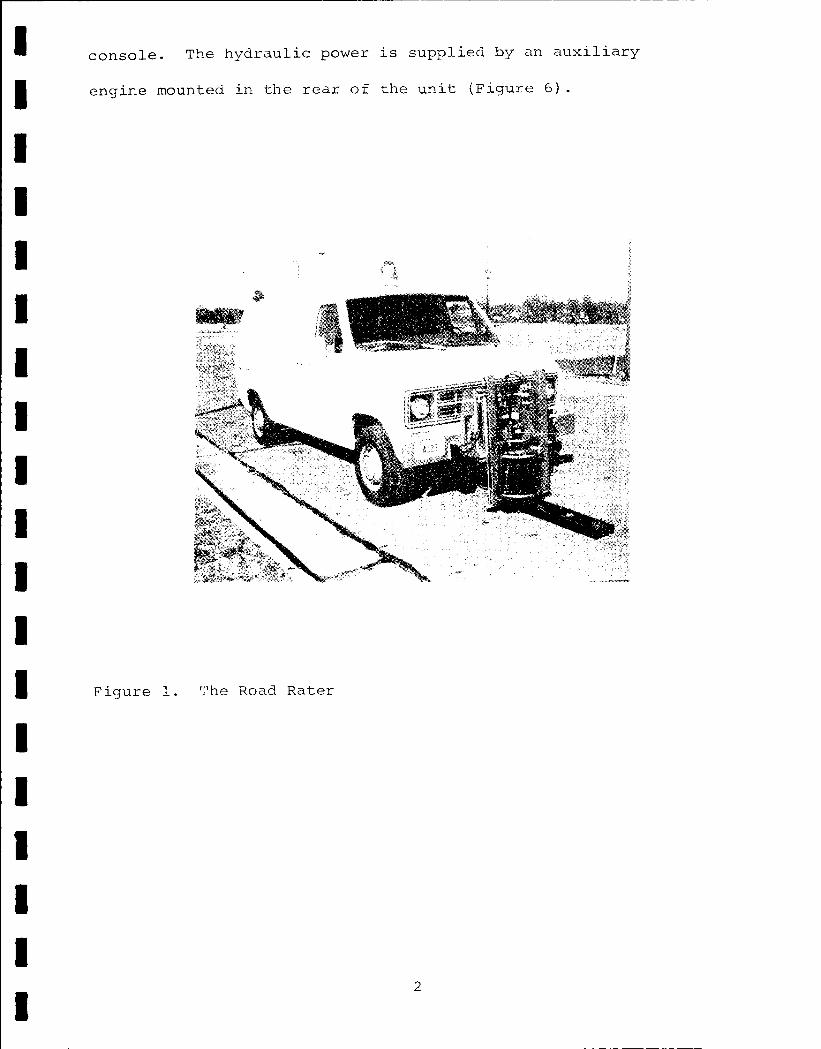
The Road Rater is an electronically controlled hydraulically
powered unit mounted on the front of a van type vehicle (Figure
1). A servo valve allows a pulsating flow of hydraulic fluid that
imparts a movement into a large mass mounted in the center of the
unit. The resultant movement of this mass produces a force that
is applied to the pavement. This dynamic loading varies from 800
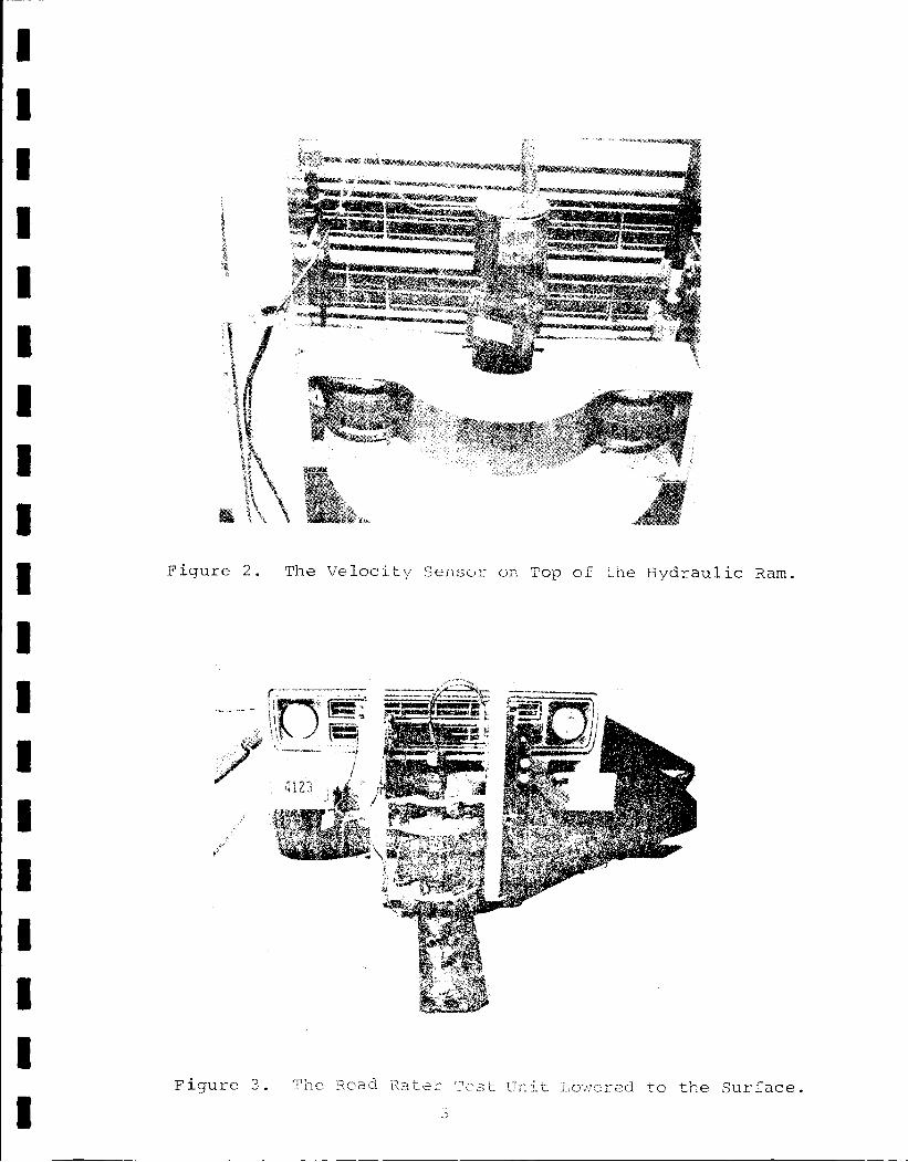
to 2000 pounds. The force being applied to the pavement is monitored
by a velocity sensor (Figure 2) attached to the top of the two-way
hydraulic ram that produces the movement. The resultant movement
of the roadway surface is measured by identical sensors that are
lowered to the surface (Figures 3 and 4). An electronic console
(Figure 5) containing the controls to regulate the magnitude
and frequency of the loading is located next to the driver
inside of the vehicle. The resultant movement as indicated by the·
roadway velocity sensors is displayed on meters contained in the
I I I I I I I I I I I I I I I I I I I
console. The hydraulic power is supplied by an auxiliary
engine mounted in the rear of the unit (Figure 6).
Figure 1. The Road Rater
2
I I I I I I I I I I I I I I I I I I I
Figure 2. The Velocity Sensor on Top of the Hydraulic Ram.
Figure 3. rn1e So ad i~a te::::- '"est Ur: it Lov1ered to the Surface.
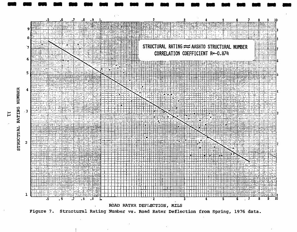
ROAD RATER DEFLECTION, MILS Figure 7. Structural Rating Number vs. Road Rater Deflection from Spring, 1976 data.
I I I I I I I I I
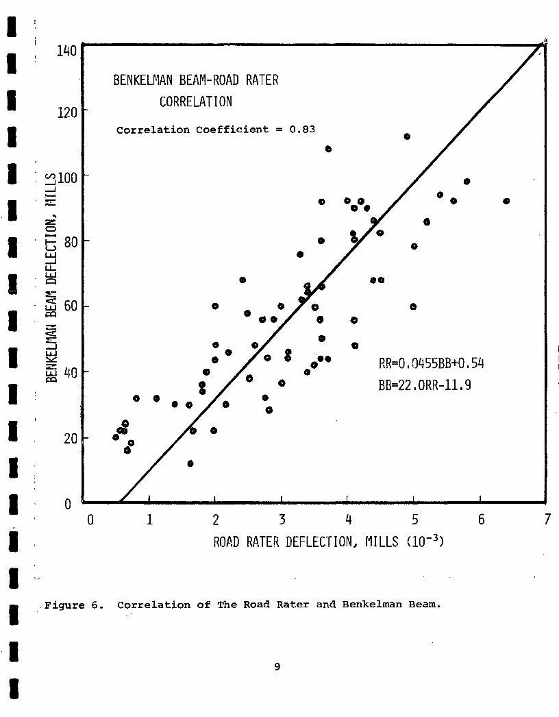
The correlation of this data indicated confidence in the
AASHTO procedure can be strengthened. After trials with other
plots, a log-log basis was selected to avoid a nonlinear regression
line. The correlation shown in Figure 7 resulted in a correlation
coefficient of -0.874. There appears to be no major inconsistencies
in the data points.
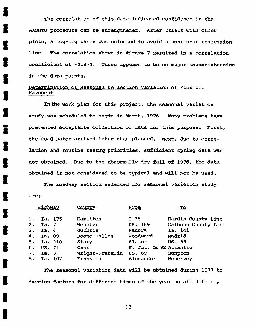
Determination of Seasonal Deflection Variation of Flexible Pavement
In the work plan for this project, the seasonal variation
study was scheduled to begin in March, 1976. Many problems have
prevented acceptable collection of data for this purpose. First,
the Road Rater arrived later than planned. Next, due to corre-
lation and routine testing priorities, sufficient spring data was
I not obtained. Due to the abnormally dry fall of 1976, the data
I I I I I I I I I
obtained is not considered to be typical and will not.be used.
The roadway section selected for seasonal variation study
are:
Highway County From To
1. Ia. 175 Hamilton I-35 Hardin County Line 2. Ia. 7 Webster us. 169 Calhoun County Line 3. Ia. 4 Guthrie Panora Ia. 141 4. Ia. 89 Boone-Dallas Woodward Madrid 5. Ia. 210 Story Slater us. 69 6. us. 71 Cass. N. Jct. :ra. 92 Atlantic 7. Ia. 3 Wright-Franklin us. 69 Hampton 8. Ia. 107 Franklin Alexander Meservey
The seasonal variation data will be obtained during 1977 to
develop factors for different times of the year so all data may
12
I I I I I I I I I I I I I I I I I I I
be related to the unstable spring deflections. Testing could be
conducted any time except when the ground is frozen and multiplied
by an appropriate factor to be related to the 11 standard 11 time of
year.
Determination of Increased Structural Capability Due to Resurfacing
The Road Rater deflection data will be very useful in deter
mining the thickness of resurfacing needed to achieve a desired
structural capability. Testing of one resurfacing project was in
cluded in 1976 where data was obtained before and after. More re
surfacing projects will be tested in 1977 to establish or support
previously established methods of determining overlay requirements.
ROAD RATER EQUIPMENT PROBLEMS
There has been a continuous problem of leakage from the air
spring system. This did not cause a problem with testing or the
results, but made it necessary to check and adjust the air pressure
periodically. A pressurized air tank was purchased so that the
pressure in the air system could be adjusted in the field at any
time.
There has been some trouble with the hydraulic system. The
hydraulic filter developed a leak and had to be replaced. Late in
the 1976 testing season a hydraulic servo valve became inoperable
and was replaced.
During the winter of 1976-77, it was noted that the front
axle suspension of the van was showing some distortion caused by
the weight of the Road Rater unit. A subsequent investigation of
13
I I I I I I I I I I I I I I I I I I I
the front axle problem showed thct Foundation Mechanics, Inc. had
not met a Federal requirement for certification of the load carrying
capacity of the front axle after modification.
Foundation Mechanics was contacted about the front sus
pension and indicated a willingness to aid in correcting the
problem. They contacted Ford Motor Company and requested information
and assistance. Ford personnel were very helpful in giving advice
on the suspension needs considering tlE particular loading appli-
ca tiai. Ford Motor Company, however, has a policy that they will
not recertify any unit.
Stronger springs were installed at the front axle. During
this installation and inspection of the front suspension, both
front suspension assemblies were found to be bent and required
straightening.
Aft~r consideration of all aspects including mounting the test
unit at the rear of the unit, a decision was made to use the Road
Rater as originally constructed with the modification of the stronger
springs and the straightened axles. This suspension problem rendered
the Road Rater unit inoperable for March and April, 1977. This has
caused the testing program to be delayed and some proposed testing
may not be completed as scheduled. A careful surveillance of this
problem will be necessary and the condition will be reviewed
continually.
14
I I I I I I I I I I I I I I I I I I I
Deflection Variation Caused by Pavement Temperature
Pavement temperature has a definite bearing on the resultant
deflection of flexible pavements. Higher temperatures caused
greater deflections and lower temperatures yield decreased de
flections. Again, the objective would be to establish this re
lationship so all data could be related to a "standard" temperature.
A Raytek remote reading infrared surface temperature gun has been
purchased to obtain pavement temperature. The gun has been tested
for accuracy against a thermocouple both in the laboratory and in
the field. There is good correlation at pavement temperatures
above 90° F.and below 600 F the infrared gun yields poor results.
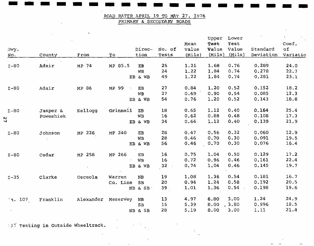
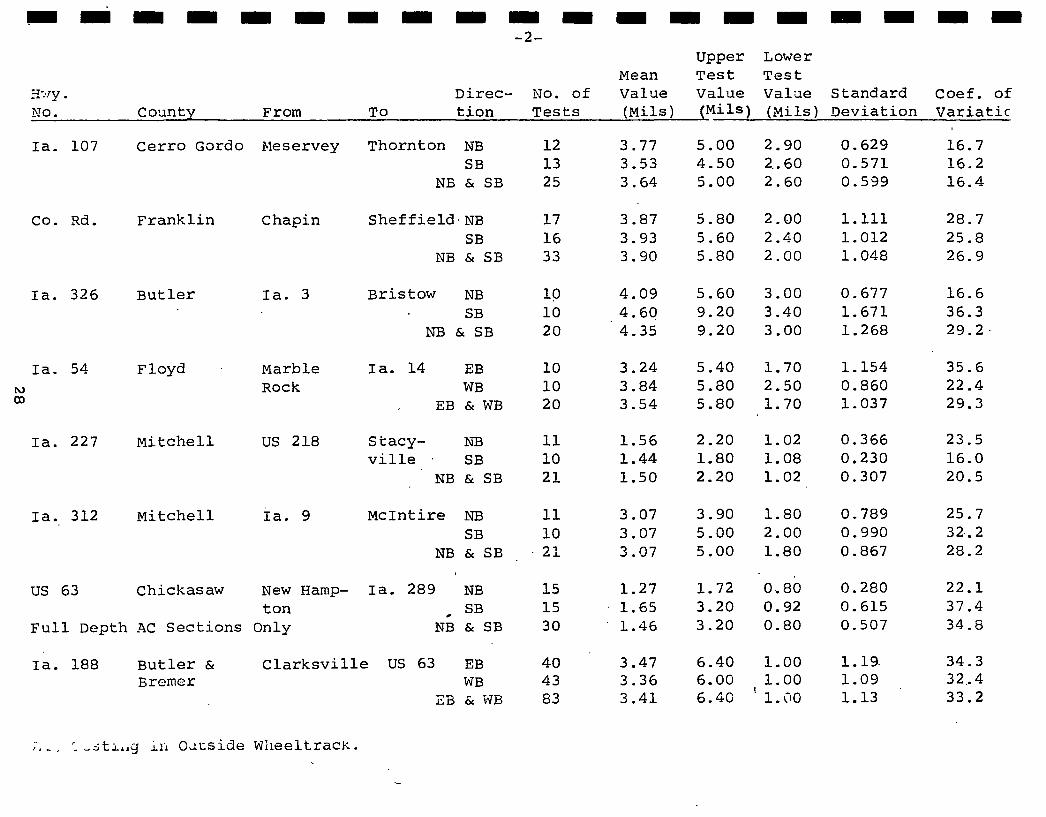
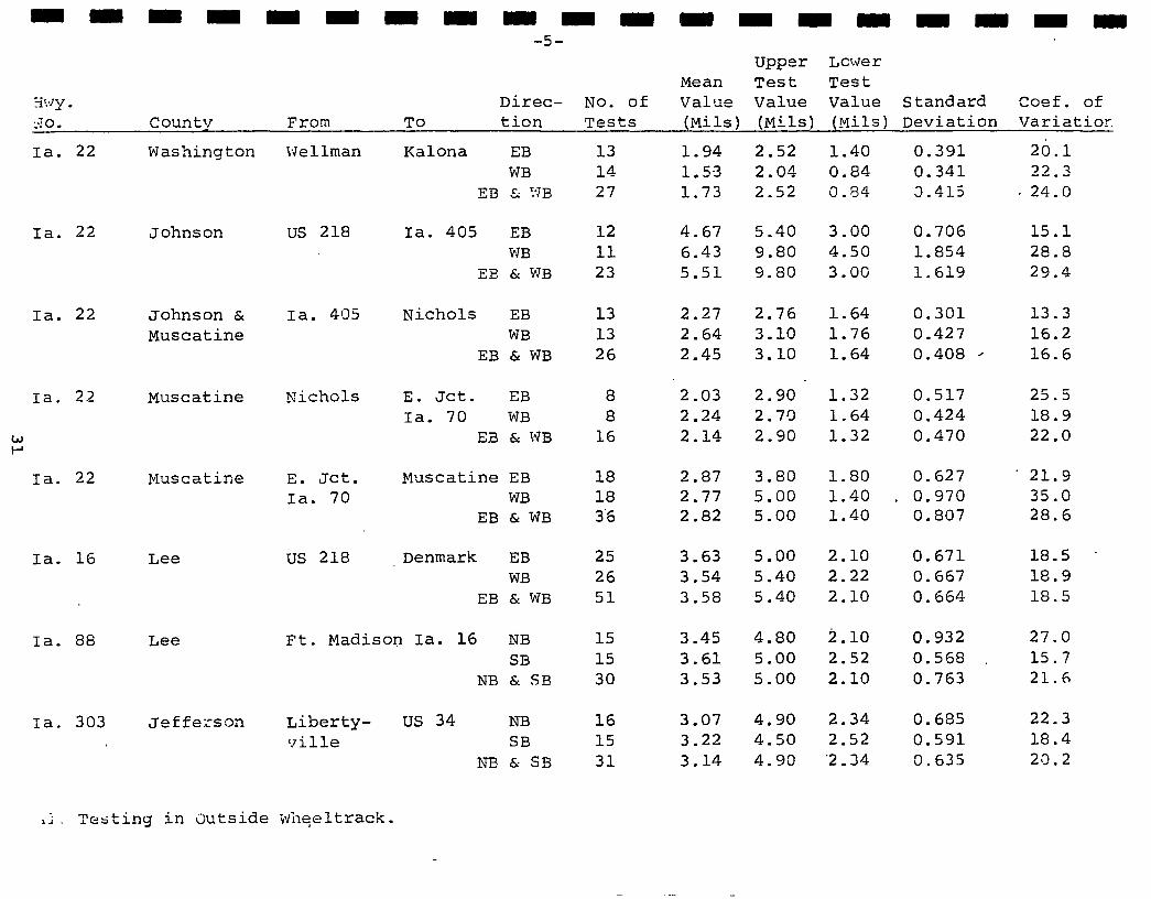
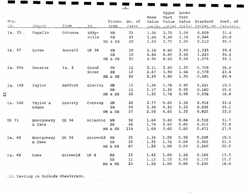
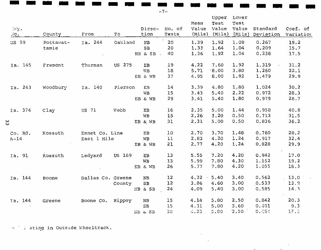
Summary of 1976 Road Rater Deflection Data
The 1976 summary of deflection data is given in Appendix C.
The Road Rater has demonstrated its ability to increase the
quantity of testing. With this greater capacity for testing,
an inventory program can be initiated. The goal will be to estab
lish structural ratings for all primary flexible roadways in Iowa.
Specific requests for pavement deflection testing will, however,
continue to be given priority. As can be noted from the summary,
only a limited amount of testing has been conducted on the
secondary system.
15
I I I I I I Appendix A
Method of Test for Determining Pavement Deflection
I Using The Road Rater
I I I I I I I I I I I I 16
I I I I I I I I I I I I I I I I I I I
Test Method No. Iowa 1009-A June 1977
IOWA DEPARTMENT OF TRANSPORTATION HIGHWAY DIVISION
Office of Materials
METHOD OF TEST FOR DETERMINING PAVEMENT DEFLECTION USING THE ROAD RATER
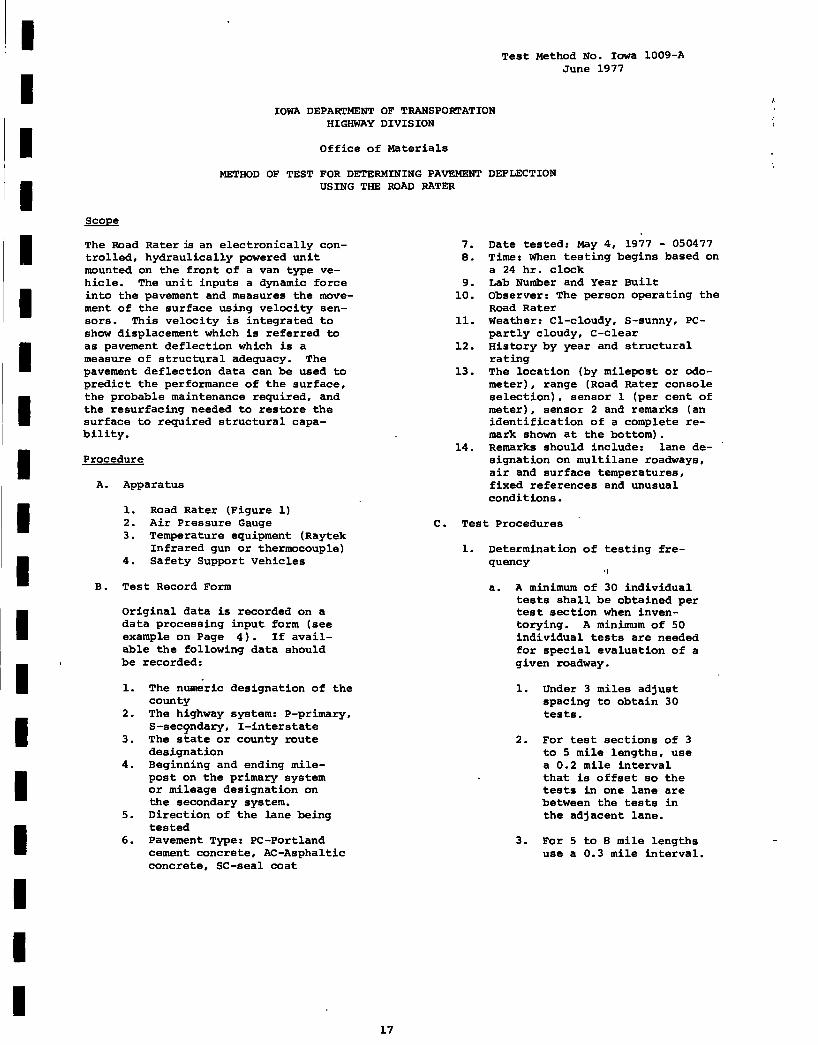
The Road Rater :is an electronically controlled, hydraulically powered unit mounted on the front of a van type vehicle. The unit inputs a dynamic force into the pavement and measures the movement of the surface using velocity sensors. This velocity is integrated to show displacement which is referred to as pavement deflection which is a measure of structural adequacy. The pavement deflection data can be used to predict the performance of the surface, the probable maintenance required, and the resurfacing needed to restore the surface to required structural capability.
Procedure
A. Apparatus
l. Road Rater (Figure l) 2. Air Pressure Gauge 3. Temperature equipment (Raytek
Infrared gun or thermocouple) 4. Safety Support Vehicles
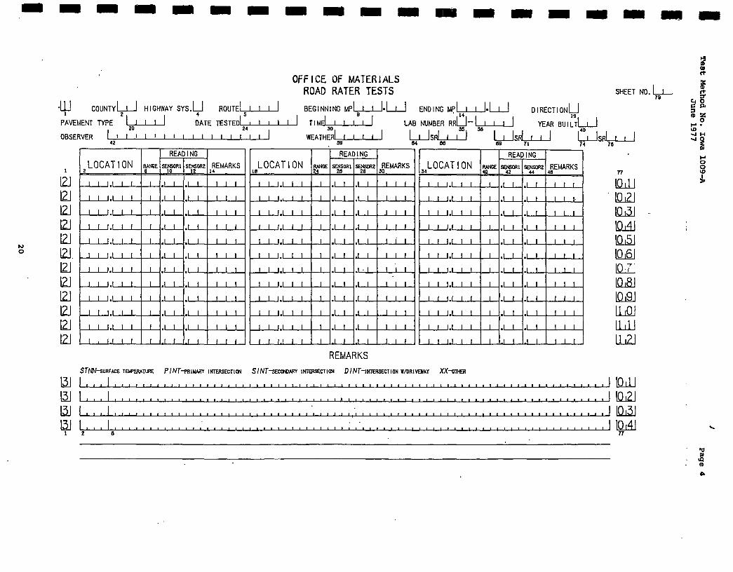
B. Test Record Form
Original data is recorded on a data processing input form (see example on Page 4). If available the following data should be recorded:
1. The nuaeric designation of the county
2. The highway system: P-primary, S-sec9ndary, I-interstate
3. The state or county route designation
4. Beginning and ending milepost on the primary system or mileage designation on the secondary system.
13. The location (by milepost or odometer), range (Road Rater console selection), sensor l (per cent of meter), sensor 2 and remarks (an identification of a complete remark shown at the bottom).
14. Remarks should include: lane designation on multilane roadways, air and surface temperatures, fixed references and unusual conditions.
c. Test Procedures
l. Determination of testing fre-quency
·1
a. A minimum of 30 individual tests shall be obtained per test section when inventorying. A minimum of 50 individual tests are needed for special evaluation of a given roadway.
1. Under 3 miles adjust spacing to obtain 30 tests.
2. For test sections of 3 to 5 mile lengths, use a 0.2 mile interval that is offset so the tests in one lane are between the tests in the adjacent lane.
3. For 5 to 8 mile lengths use a 0.3 mile interval.
I I I I I I I I I I I I I I I I I I I
Test 'lethod !:o. Iciw:: 1009-A ,J"'1.ne l9T7
b.
.).
b.
c.
d.
·+. sEctio:::s ,7-reater Jes in length, ;:iile ir:tcrval.
'les:-.i:-:(:r :--r-c:q:uency shall be as nuter_l or r3 i rec ted by the ·2'.•SL'Cr':· ··C'r special test sec'.~_: or,s.
t>- :::J '-- _j_,' :J
cr.:Jir·e 2rid c:1llow to ~i ~ ~inut0 warm-
Cl-:.ec~c ,1j _ _:_- p2:-essu.re in t~1e
t·,..;o ·,1'.Jne r ,1. ir spr ir::.gs wi tr. a 9ood tire air pressure g0ug0. hd~ air if required to bri!·O t 11e sr>ri~g pressure to ·~ ()+·- :Js i.
e. :!-:eek .1ir 9ressure in the six CE;:. ter ~iii· sprinqs. This c'.:eck :rus '.:_ }JE· :--:1acle with the S~-:!a_,_ l ·.-:=:i ·0 t~1at sep0rates
1.:hc L-.10 .3£•ts of air springs .in tl·E oDer, posicion (clockwis to c~e~). Add air as rn,·~·T i1e ,-C:'-''.'-~:i red to bring
LO CAT I ON RANGE SENSOR! SENSORZ REMARKS LOCATION RANGE SENSOR! SENSOR2 REMARKS LO CAT I ON RANGE SENSOR! SENSOR2 REMARKS 2 8 10 12 14 18 24 26 28 30 34 40 42 44 46
REMARKS STNN-suRFACE TEMPERATURE PI NT-PRIMARY INTERSECTION SI NT-sECONDARY INTERSECTION DI NT-1NTERSEcnoN W/DR!VEWAY XX-oTHER
n
lQJJ 10121
10131
10141
10151
10161
JOT K18J llli9J lLQJ lLlJ U2J
-I-! ID ID rt
I I I I I I I I I I I I I I I I I I I
~p.pendix B
Method of Test for Determing Pavement Deflection Using the Benkelman Beam
21
I I I I I I I
I I .1
I I I I I I I I
Test Method No. Iowa 1006-A February 1971
IOWA STATE HIGHWAY COMMISSION
Materials Department
METHOD OF TEST FOR DETERMINING PAVEMENT DEFLECTION
USING THE BENKLEMAN BEAM
Scope
The Benkelman Beam is used to determine the deflection of road surfaces under an 18,000 pound axle load. Information gathered from the Benkelman Beam studies is an indication of structural adequacy. The resulting information can be used to predict the performance of the surface, the probable maintenance required, and the resurfacing needed to restore the surface to required structural adequacy.
Procedure
A. Apparatus
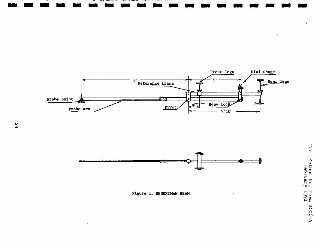
1. Benkelman Beam (Fig. 1)
2. Truck with 18,ooo pound axle load.
3. Watch with sweep hand.
4. Thermometer or thermocouple.
5. Safety support vehicles (3).
B. Test Record Form
Original data is recorded in a field book having the following columns:
1. Station or miles.
2. Lane.
3. Position (inside or outside wheel track).
4. L0 (initial reading).
5. Li (intermediate reading).
6. Lr (final reading).
7. 6 (vertical displacement of front legs).
8. True Deflection.
Entries of the air and surface temperature, date, time and remarks are also made in the field book.
22
C. Test Procedure
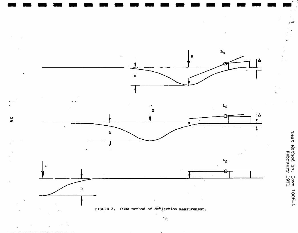
The test is conducted according to the Canadian Good Roads Association (CGRA) method as follows (Fig. 2):
1. The rear wheels of the truck are stopped on the selected station or odometer reading.
2. The probe point of the Benkelman Beam is placed between the rear dual wheels of the truck in the wheel track being tested.
3. The dial is observed until the rate of movement is less than 0.001 inch per minute at which time the initial reading (L0 ) is noted and recorded.
4. The truck is then moved ahead 8 1 -
4-1/211 (the distance from the probe point to the front legs) and again the reading (Li) is not taken and recorded until the movement is less than 0.001 inch per minute.
5. The rear wheels are then moved 30 ft. ahead of the probe point and the final reading (Lr) is taken and recorded in the same manner as above.
D. Precautions
1. The beam should be vibrated to relieve any friction by lightly tapping it near the pivot on top with the fingers.
2. The beam is quite sensitive and should not be used when the wind is adversely affecting the readings.
3. A constant (K) should be for each Benkelman Beam. stant for the I.S.H.C. 's beam is 2.90.
determined The con
present
I I I I I I I
I I I I I I I I I I
2
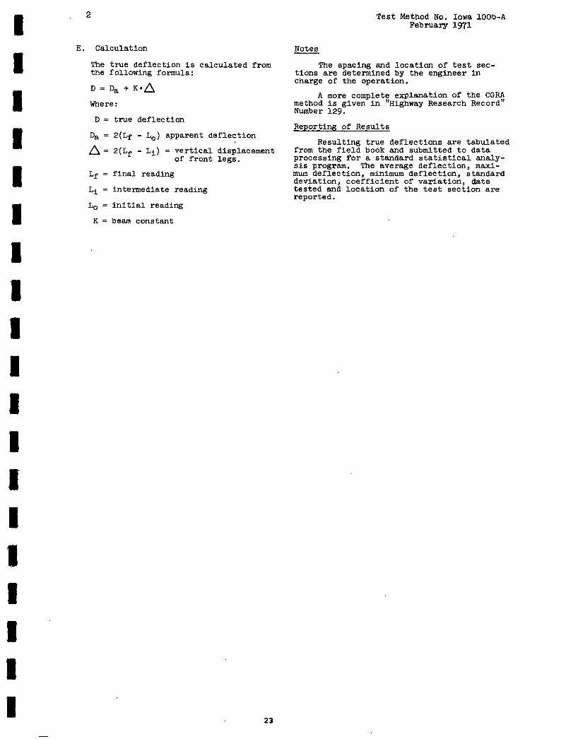
E. Calculation
The true deflection is calculated from the following formula:
D=Da+K•,6
Where:
D true deflection
Da 2(Lf - Lo) apparent deflection
.6 = 2(Lf - Li) = vertical of front
final reading
intennediate reading
L0 initial reading
K = beam constant
displacement legs.
23
~
Test Method No. Iowa lOOb-A February 1971
The spacing and location of test sections are detennined by the engineer in charge of the operation.
A more complete explanation of the CGRA method is given in "Highway Research Record" Number 129.
Reporting of Results
Resulting true deflections are tabulated from the field book and submitted to data processing for a standard statistical analysis program. The average deflection, maximum deflection, minimum deflection, standard deviation, coefficient of variation, date tested and location of the test section are reported.
Mean Test Test H\·ly. Direc- NO. , of Value Va.ltie Val'...le Stan_dard coc:f. of No. Co:.rnty Fro:n To ti on Tests (Mils_) (Nils) (;-1.ils) Deviation \iar iatio:
Mean Test Test :I<:;y. Direc- NO. of Value Value Value Standard Coef. of . ·,-.. . .,r·· .,,....,.,. f'!:"Offi 'I"O C.J.011 !'S:::>C:.:3 (.·11. i_::; j U·iLi...;:;i 0=-v·iat~-~~
-- . -• ....... '- ._, \.J.J. J. :_ I \.·ll..:...S) \f :::...::- l...::. c.:..:... -
Mean Test Test .. i.~.·l":l. Di rec- ~'Jo. cf Value Value Value Standard coef. of ~o. County From TO ti on Tests (Mils) (Mils) (Mils) Deviation Variaticr:
I a. 144 Greene & us 30 Ia. 175 NB 32 3.85 5.80 2.40 0.746 19.4 ·w.~bster SB 32 3.93 5.80 2.30 0.831 21. l


![[PPT]Inter-Rater Reliability - Home - Ivy Tech Community … · Web viewInter-Rater Reliability Respiratory Ivy Tech Community College-Indianapolis What Is Inter-Rater Reliability](https://static.documents.pub/doc/80x56/5aefd30e7f8b9a572b8ea7b7/pptinter-rater-reliability-home-ivy-tech-community-viewinter-rater-reliability.jpg)


