37
Progress towards nanometre-level beam stabilisation at ATF2 N. Blaskovic, D. R. Bett, P. N. Burrows, G. B. Christian, C. Perry John Adams Institute, University of Oxford
| Date post: | 23-Dec-2015 |
| Category: |
Documents |
| Upload: | hester-wheeler |
| View: | 214 times |
| Download: | 1 times |

Progress towards nanometre-level beam stabilisation at ATF2
N. Blaskovic, D. R. Bett, P. N. Burrows,G. B. Christian, C. Perry
John Adams Institute, University of Oxford

Outline
Neven Blaskovic 2
• Introduction– Feedback at a linear collider– International Linear Collider– Feedback on Nanosecond Timescales
• Experimental setup at Accelerator Test Facility• Position jitter on waist• Interaction point feedback results

Introduction
Feedback at a Linear Collider
Neven Blaskovic 3
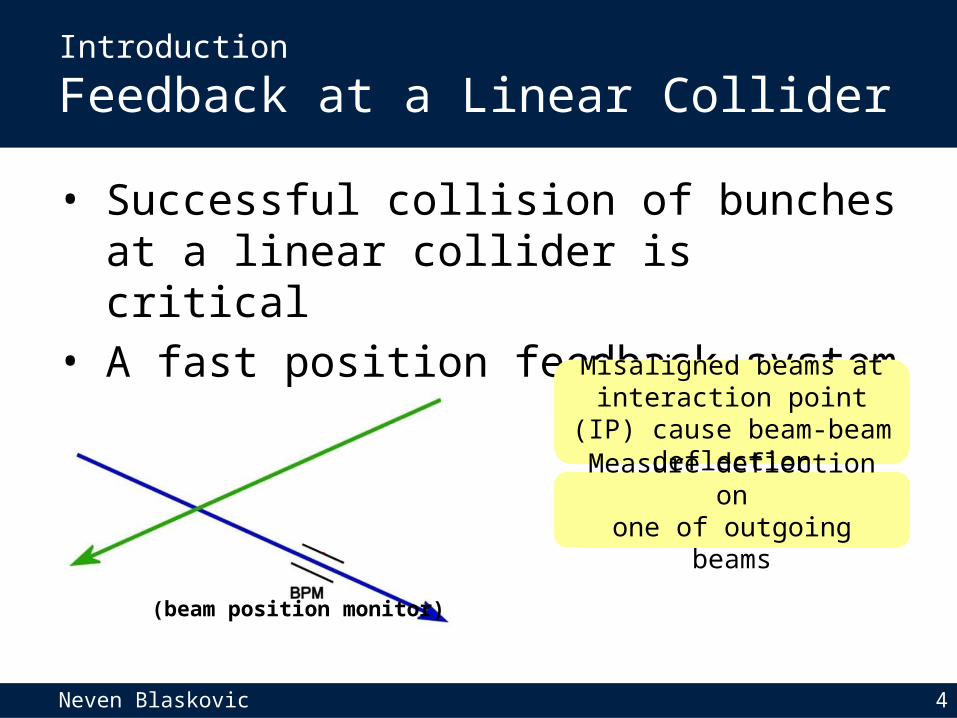
• Successful collision of bunches at a linear collider is critical
• A fast position feedback system is required
Misaligned beams at interaction point (IP) cause
beam-beam deflection
Neven Blaskovic 4
• Successful collision of bunches at a linear collider is critical
• A fast position feedback system is required
Introduction
Feedback at a Linear Collider
Misaligned beams at interaction point (IP) cause
beam-beam deflection
Measure deflection onone of outgoing beams
(beam position monitor)

Neven Blaskovic 5
• Successful collision of bunches at a linear collider is critical
• A fast position feedback system is required
Misaligned beams at interaction point (IP) cause
beam-beam deflection
Measure deflection onone of outgoing beams
Correct orbit of next bunch (correlated to previous bunch due to short bunch spacing)
(beam position monitor)
Introduction
Feedback at a Linear Collider

Introduction
International Linear Collider (ILC)
Neven Blaskovic 6
• Proposed linear electron-positron collider• Centre-of-mass energy: 250-1000 GeV• Vertical beamsize: 5.9 nm• Bunch separation: 554 ns
(ILC Technical Design Report)

Introduction
Accelerator Test Facility (ATF) at KEK
Neven Blaskovic 7
• Test bed for the International Linear Collider• Facility located at KEK in Tsukuba, Japan• Goals of the present accelerator (ATF2):– 37 nm vertical spot size at final focus– Nanometre level vertical beam stability

Introduction
Accelerator Test Facility (ATF) at KEK
Neven Blaskovic 8
Electron source
90 meters

Introduction
Accelerator Test Facility (ATF) at KEK
Neven Blaskovic 9
1.28 GeV linear accelerator
Electron source
90 meters

Introduction
Accelerator Test Facility (ATF) at KEK
Neven Blaskovic 10
Damping ring
Electron source
1.28 GeV linear accelerator
90 meters

Introduction
Accelerator Test Facility (ATF) at KEK
Neven Blaskovic 11
Damping ring
Electron source
Extraction lineFinal focus
Model interaction point (IP) of a collider(location of feedback system)
1.28 GeV linear accelerator
90 meters

Introduction
Accelerator Test Facility (ATF) at KEK
Neven Blaskovic 12
• ATF can be operated with 2-bunch trains in the extraction line and final focus
• The separation of the bunches is ILC-like (tuneable up to ~300 ns)
• Our prototype feedback system:– Measures the position of the first bunch– Then corrects the path of the second bunch
• Train extraction frequency: ~3 Hz

Introduction
Feedback on Nanosecond Timescales (FONT)
Neven Blaskovic 13
• Low-latency, high-precision feedback system• We have previously demonstrated a system
meeting ILC latency, BPM resolution and beam kick requirements
• We have extended the system for use at ATF• We aim for nanometre level beam stabilisation
at the ATF IP

Neven Blaskovic 14
IPB Cavity BPM at beam waist
• C-band: 6.4 GHz in y• Low Q: decay time < 30 ns• Resolve 2-bunch trains
Experimental Setup
IPBbeam

Neven Blaskovic 15
for cavity BPM
• Analogue, 2-stage downmixer• Resolution of < 80 nm• Developed by Honda et al.
Processor
Experimental Setup
IPB
Proc
esso
rbeam

Neven Blaskovic 16
Board
• 9 ADC channels at 357 MHz• 2 DAC channels at 179 MHz• Xilinx Virtex 5 FPGA
Experimental Setup
IPB
Proc
esso
r
Board
beam

Neven Blaskovic 17
• Made by TMD Technologies• ± 30 A drive current• 35 ns rise time (90 % of peak)
Amplifier
Experimental Setup
Ampl
ifier
IPB
Proc
esso
r
Board
beam

Neven Blaskovic 18
IPK
Ampl
ifier
IPB
Proc
esso
r
Board
• Vertical stripline kicker• 12.5 cm long strips for IPK• Just before IP chamber
IPK Kicker
Experimental Setup
beam

Neven Blaskovic 19
Position Jitter
Measured position jitter on waist ~ 75 nm

Neven Blaskovic 20
Position Jitter
A few hours later, measured position jitter > 200 nm

Neven Blaskovic 21
Position Jitter
Using a downstream BPM, the waist position was found to have driftedCorrecting for waist drift off-line recovers waist beam jitter ~ 75 nm
Resolution
Neven Blaskovic 22
• The ~75 nm measured jitter is an upper limit to the resolution of the BPM, for the single-point sampling used in the feedback firmware

Off-line analysis shows that multi-sample averagingimproves the resolution to under 40 nm
Resolution
Neven Blaskovic 23
• The ~75 nm measured jitter is an upper limit to the resolution of the BPM, for the single-point sampling used in the feedback firmware

Neven Blaskovic 24
Interaction Point Feedback
• IPB position is used to drive the local kicker IPK
• Latency: 212 ns• Effect measured at IPB
IPK
Ampl
ifier
IPB
Proc
esso
r
Board
beam

Neven Blaskovic 25
Interaction Point Feedback

Neven Blaskovic 26
Interaction Point Feedback

Conclusions
Neven Blaskovic 27
• Demonstrated low-latency, high-precision, intra-train feedback systems
• Cavity BPM feedback latency: 212 ns• Cavity BPM resolution– Single-point sampling: < 80 nm– Multi-sample averaging: < 40 nm
• Achieved beam stabilisation at the ATF IP, reducing the jitter to < 90 nm

Thank you for your attention!
Neven Blaskovic 28
Cavity BPM Signal Processing
Neven Blaskovic 29
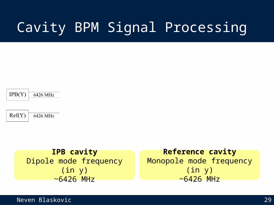
Reference cavityMonopole mode frequency (in y)
~6426 MHz
IPB cavityDipole mode frequency (in y)
~6426 MHz

Neven Blaskovic 30
Cavity BPM Signal Processing
The IPB and reference cavity signals are downmixedusing a common, external 5712 MHz local oscillator (LO)
simplified schematic

Neven Blaskovic 31
Cavity BPM Signal Processing
The IPB signal is downmixed using the reference cavity signal as LOThe I and Q output signals at baseband are used to obtain the beam position
simplified schematic

Neven Blaskovic 32
Methods to Improve Resolution
Using multi-sample averagingtakes the measured jitter from ~75 nm to ~40 nm

Neven Blaskovic 33
Methods to Improve Resolution
Removing correlation with bunch phase, charge and off-waist BPMtakes the measured jitter from ~75 nm to ~50 nm and <40 nm with averaging

Neven Blaskovic 34
Methods to Improve Resolution
Jitter (nm)Remove correlation with
off-waist BPM bunch phase, charge & off-waist BPM
Single-sample 76 49Multi-sample 42 39
On-waist jitter measurement gives upper limit on BPM resolution
In green, the level of resolution used in feedback so far

Ground Motion vs. Frequency
Neven Blaskovic 35
Vertical ground motion power spectral density integrated up from a range of cut-off frequencies to give the RMS ground motion as a function of frequency
R. Amirikas et al.

Monopole and Dipole Cavity Modes
Neven Blaskovic 36
Y. Inoue et al.
Monopole modeTMrφz = TM010
Dipole modeTMrφz = TM110
Electric fieldposition independent
Electric fieldproportional to position

Neven Blaskovic 37
Interaction Point Feedback
first bunch uncorrected
second bunch correctedBe
am w
aist
sca
n


