Page 1
1
Progressive Collapse Analysis of Steel Structures under Fire Conditions
By Ruirui Sun1,*
, Zhaohui Huang2 and Ian Burgess
3
ABSTRACT
In this paper a robust static-dynamic procedure has been developed. The development extends
the capability of the Vulcan software to model the dynamic and static behaviour of steel
buildings during both local and global progressive collapse of the structures under fire conditions.
The explicit integration method was adopted in the dynamic procedure. This model can be
utilized to allow a structural analysis to continue beyond the temporary instabilities which would
cause singularities in the full static analyses. The automatic switch between static and dynamic
analysis makes the Vulcan a powerful tool to investigate the mechanism of the progressive
collapse of the structures generated by the local failure of components. The procedure was
validated against several practical cases. Some preliminary studies of the collapse mechanism of
steel frame due to columns‘ failure under fire conditions are also presented. It is concluded that
for un-braced frame the lower loading ratio and bigger beam section can give higher failure
temperature in which the global structural collapse happens. However, the localised collapse of
the frame with the higher loading ratio and smaller beam section can more easily be generated.
The bracing system is helpful to prevent the frame from progressive collapse. The higher lateral
stiffness of the frame can generate the smaller vertical deformation of the failed column at the re-
stable position. However, the global failure temperature of the frame is not sensitive to the lateral
stiffness of the frame.
KEYWORDS: Progressive Collapse, Steel Frame, Explicit Integration, Combined Analysis,
Local Instability, Bracing system.
1,* PhD Research Student, Department of Civil and Structural Engineering, the University of
Sheffield, Sheffield, S1 3JD, UK. Tel: +44-(0)114-2225726, Fax: +44-(0)114-2225700, Email:
[email protected]
2 Reader, School of Engineering and Design, Brunel University, Uxbridge, Middlesex, UB8 3PH,
UK.
3 Professor, Department of Civil and Structural Engineering, the University of Sheffield,
Sheffield, S1 3JD, UK.
Page 2
2
1. Introduction
Structural engineers have a responsibility for incorporating fire safety into their building designs
in order to minimize loss of life and property. The collapse of the twin towers of the World
Trade Centre in New York was a reminder of the potential of fire to cause devastating failures of
high-rise buildings by initiating progressive collapse. At present, steel structures have been
widely used in the multi-story buildings because they are ideally suited to the current drive for
improved construction efficiency as labour costs increase. However, the material properties of
steel reduce significantly at elevated temperatures. For example, at 700°C the strength of steel is
only 23% of ambient-temperature strength. At 800°C this has reduced to 11% and at 900°C to
6%. Therefore, fire resistance design of steel buildings is a major concern to the structural
engineers.
Currently, for structural fire engineering design, there is a trend that more designers will adopt
the performance-based design approach. That means structures are treated integrally in structural
fire safety design. For last two decades, extensive research has been carried out on the behaviour
of steel-framed buildings under fire conditions. The Cardington full-scale fire tests [1]
demonstrate that the real behaviour of structural elements can be very different from that
indicated by standard furnace tests. In real buildings structural elements form part of a
continuous assembly, and building fires often remain localized, with the fire-affected structure
receiving significant restraint from cooler areas surrounding it. If such interactions are to be used
by designers in specifying fire protection strategies as part of a performance-based structural
design approach, then this cannot practically be based on large-scale testing because of the
extremely high implicit costs. It is therefore becoming increasingly important that software
models be developed to enable the behaviour of such structures to be predicted with sufficient
accuracy under fire conditions. In recent years many researchers have developed numerical
models to simulate the behaviour of steel or steel-composite frame in fire. For example, Wang
and Moore [2] built a three dimensional model of a steel frame with semi-rigid connection to
study the structural behaviour in fire. A computer program Vulcan has been developed at the
University of Sheffield for three-dimensional modelling of steel, steel-framed composite and
reinforced concrete buildings in fire [3-7]. The computer program FEMFAN from the Fire
Page 3
3
Engineering Research Group at Nanyang Technological University has been used by Tan et al.
[8-11], to study the behaviour of a number of steel frames under fire conditions. Franssen et al.
[12] developed a computer program SAFIR, which was used by many researchers [13-15]. Also
a number of researchers [16-24] used commercial FEA software ABAQUS to carry out the
structural analysis of steel frames at elevated temperatures. The most of above mentioned
analyses are based on static analysis. It is clear that static analysis is computational effective for
modelling structural behaviour in fire in which the loading time is longer (from 0.5 to 4 hours).
However, a shortcoming of static analysis is that the analyses would be terminated by numerical
singularity or structural instability due to any localised members' failure.
Progressive collapse occurs when an initial local failure spreads from element to element,
eventually resulting in collapse of a disproportionately large or entire part of a structure. Tan
and Astaneh-Asl [25] experimentally studied the effective tying of steel structure subject to
failure of key members and proposed a method to prevent progressive collapse using steel cables.
Izzuddin et al. [26, 27] investigated the progressive collapse of multi-storey composite buildings
modelled by a two-dimensional model. Liew [28] built a mix-element model to study three
dimensional steel frames subject to blast load and fire attack. The model is capable of capturing
detailed behaviour of member and frame instability associated with the effects of high-strain rate
and fire temperature. Lien et al. [29] proposed the Vector Form Intrinsic Finite Element analysis
of nonlinear behaviour of steel frame. They studied the behaviour of steel frame under fire
induced by earthquake and concluded that the deformation of structure is significantly affected
by the aftershock, fire and fracture of structural element.
The robustness of structure is the ability of the structure to prevent from disproportional failure
after the local damage arisen by accidental actions. Hence, in order to assess of the robustness of
structure in fire conditions, it is necessary to make sure that the analysis can go further after local
instability taking place. Some researchers have tried to overcome this shortcoming of static
analysis by carrying out full dynamic analysis for the whole duration of fire. Because the time of
fire loading is relative long, hence the computation is very expansive. Therefore, the main
objective of this paper is to develop a robust simplified numerical procedure in which the whole
behaviour of a load-controlled structure can be modelled effectively. The model developed
Page 4
4
combines the static and dynamic analysis together to make full use of their advantages. Static
analysis can be used to trace the behaviour of the structures at elevated temperature until the
instability happened. After the instability of the analyses is identified, the dynamic procedure
will be activated to continue the analysis. In this paper, an explicit dynamic procedure has been
developed to allow modelling of the collapse of structural frames in fire. The model developed
can be used to overcome the instabilities encountered in previous static analyses, and any re-
stabilisation of the frame at high deflections can be identified. After the re-stabilisation of the
frame gained the procedure will switch to static analysis again. The procedure developed was
comprehensively validated. A series of parametric studies was conducted to investigate the
mechanism of progressive collapse of planar steel frame due to the individual column failure.
2. Non-linear procedure
2.1 Dynamic Procedure
The general equation of a body motion can be expressed as:
( ) ( ) (1)
Where is the mass matrix, is damping matrix, ( ) is the internal force vector and ( ) is
external force vector; , , and are time, displacement, velocity and acceleration vectors,
respectively.
In order to solve Eq. (1) the direct-integration dynamic procedure provides two general operators:
the implicit integration and explicit integration methods. In implicit dynamic analysis the
integration operator matrix must be inverted and a set of nonlinear equilibrium equations must be
solved at each time increment. But, for explicit one, no global mass or stiffness matrices need to
be formed and inverted because displacements and velocities are calculated in terms of quantities
that are known at the beginning of a time increment, thus, the calculation at each increment is
relatively inexpensive compared to an implicit integration scheme.
Since implicit dynamic procedure requires forming and inverse the global stiffness matrix, hence,
more disk space and memory are needed compared to explicit dynamic. Thus, for large scale
problem explicit dynamic will be more effective than implicit one. Moreover, for problems with
high nonlinearity or material complexity, the implicit dynamic would have difficulty to get a
Page 5
5
converged solution, resulting in either a large number of iterations needed or numerical failure of
the analysis. Since the high nonlinearity due to material degradation, failure of members and the
local and global instability presented in the collapse of the structural frame, in this research
explicit method is adopted as integration method for dynamic analysis.
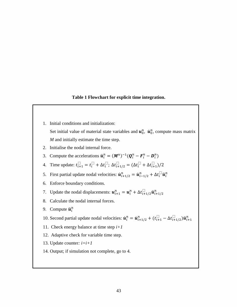
Time integration
In the developed explicit dynamic procedure, central difference integration is used to integrate
the equation of motion explicitly through the time, using the kinematic conditions at the current
increment i to calculate the kinematic conditions at the next increment, i+1. That is,
(2)
(3)
Where and
are the displacement and velocity of degrees of freedom (DOF) n at i-th time
step, is the time step and the subscript i refers to the current increment number of dynamic
steps, ( ) . The key to the computational efficiency of the explicit
procedure is the use of diagonal elements of mass matrices because the acceleration at the
beginning of the increment is computed by:
( ) (
) (4)
Where, is the acceleration of DOF n at i-th time step, is the mass of DOF n,
is the
applied load, and and
are the internal and damping force vectors, respectively. In this
procedure the time increments must be quite small so that the accelerations are nearly constant
during an increment. Since the time increments are small, analyses typically require many
thousands of increments. Fortunately, each increment is computationally inexpensive because
there are no simultaneous equations needed to be solved. Table 1 gives a summary and flowchart
of the explicit dynamics algorithm developed.
Mass matrix
Page 6
6
A robust beam-column element has been developed in Vulcan [4]. The cross section of the beam
column is divided into a matrix of segments and each segment may have different material,
temperature, and mechanical properties. For beam-column element in Vulcan (see Fig.1), the
configuration of the beam is characterized using global coordinate (x-y-z) and a local coordinate
(x’-y’-z’) which is located at the neutral axis of the beam. In this case, an effective way to form
lumped mass matrix is to measure the translational displacements in global coordinates (x-y-z),
but to measure the angular velocity referenced to the natural coordinate.
The motion of the finite element model is described by the displacements ,
velocities and accelerations of the node referenced to the global co-ordinate system
( and n is the number of nodes). The rotational motion of the node is described by the
angular velocities and angular accelerations . Let
and be the components
of all internal nodal force in global co-ordinate system, let
and be the
components of all external nodal force in global co-ordinate system and let
and
be the corresponding moments, expressed in terms of the natural coordinate; and then,
and
be the corresponding external applied moments, expressed in terms of the natural
coordinate. Hence, translational equations of the motion of the node n are:
(
) ( ) (5)
Here, is the translational mass at the node n in global coordinate. Then rotational equations
of the motion of the node n in nodal co-ordinate system are the usual Euler Equation [30]:
( )
(6)
( )
(7)
( )
(8)
Where and are the principal moments of inertia for node n,
,
,
and
,
,
are angular accelerations and velocities, respectively. The above expressions
about the rotational equations of motion are not well suited for an explicit finite element code
because they are nonlinear in term of w and not easy to integrate with time. Thus, it is assumed
Page 7
7
that the nodal rotational inertia is homogeneous for a node. The simplification made results in a
simper set of equations for rotational motion in global coordinates as:
(9)
(10)
(11)
The above equation can also be expressed as:
(12)
(13)
(14)
The inertia properties of the beam-column element are lumped by the following procedure:
(1) Element translational mass matrix:
The consistent mass matrices are given by the relationship:
∫
(15)
where is the density of the element material and is the shape function matrix. The lumped
procedure adopted here, which is called ‗Consistent Diagonal Lumping‘ or ‗HRZ‘ method, is
based on the consistent mass matrix. The diagonal coefficient of consistent mass matrix
associated with translational DOFs ,
, and .( ) can be computed as:
(a) Compute total mass of element, m;
(b) Compute s by adding diagonal coefficients associated with translational DOFs that are in the
same direction:
;
(c) Scale all diagonal coefficients obtained in (a) by multiplying them with :
and
;
(2) Element rotational mass:
Nodal mass moments about all three axes are assumed to be the same and calculated as:
∑ (16)
∑
(17)
Page 8
8
∑
(18)
∑ (19)
( ) (20)
(21)
Where =element cross section area, =element length, =element mass, =cross
section moments of inertia, =material density of J-th segment, =mass moment lumped to
node n , is the total number of segments of cross section and is associated to the ratio
between the mass lumped on each node with the total mass of the element.
Damping matrix
Damping in nature comes from various mechanisms. Its effect on structural response is to cause
the displacement amplitude to decay with time (dissipation of energy). In general, for the
analyses of structures, damping is assumed to be viscous or velocity-proportional for the ease of
solution. In the current study, a mass proportional damping matrix is assumed.
(22)
Where, ( ), is the damping ratio, M is the mass matrix, and are the
frequencies of the i and j-th modes, respectively.
Limitation of time step size
Taking the nonlinearity and damping into accounting, the estimation of the stable time step limit
for Beam-Column element in this procedure is:
(
) (√ ) (23)
Where L is the element length, is the damping ratio and is the reduction factor for nonlinear
system (normally, =0.4-0.8 based on experience).
√ ( )
( )( ) (24)
where is the Young‘s modulus of segment, is the density of segment, is Poisson ratio.
Page 9
9
Energy balance check
In order to discern the instable solution, the energy balance check is also developed in this
procedure. The instable solution can be easily detected by energy balance check as any
instability would result in the spurious generation of energy which leads to a violation of the
conservation of energy. Therefore, the maintenance of stability can be established by checking
the energy balance.
In central difference method, the energy W is usually integrated in time by a trapezoidal rule. The
external, internal, kinetic and damping dissipated energy are given by:
(
) (25)
(
) (26)
(27)
Here, and
represents the internal and external force at n-th time step.
The energy conservation requires that
| | ( ) (28)
Where is a small tolerance, generally on the order of 10-2
(0.05 used here).
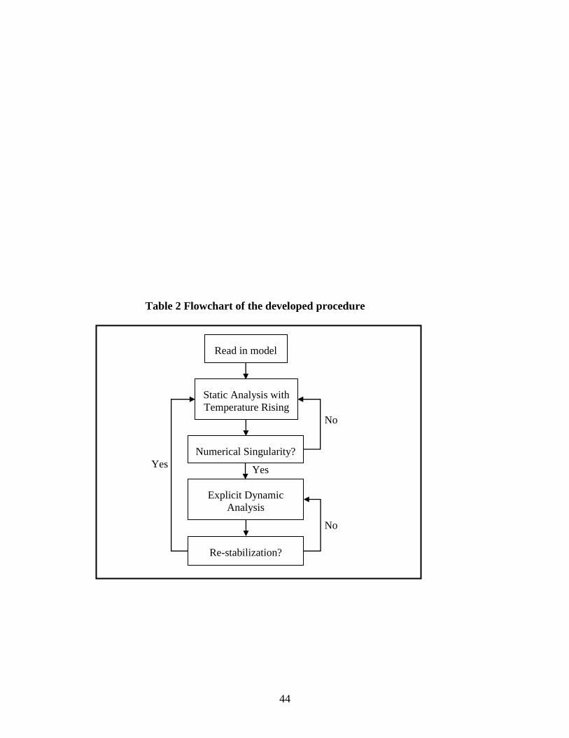
2.2. Combined static-dynamic procedure
In this paper a robust combined static-dynamic procedure has been developed to model stable
and unstable parts of the structural analysis in fire. Table 2 shows the flowchart of the developed
combined procedure. Compared to full dynamic procedure the static analysis is computationally
effective when the analyzed structure is stable at elevated temperatures. Normally, the structural
members are subjected to constant loads under fire conditions. Due to the degradation of the
materials at elevated temperatures the load capacity of the member is reduced with temperatures
increasing. At certain temperature when the load capacity of the certain members is less than the
load applied on them, the failure of the members will occur to initiate the local or global
collapses of the structure.
As shown in Table 2, once the stability of the structures is lost, the dynamic procedure can be
switched on automatically and the analysis can be carried on. It is assumed that the switch
Page 10
10
between static and dynamic analysis happens within a single temperature increment step. As
described above, the explicit scheme is adopted in the dynamic procedure. The internal energy,
external energy and kinetic energy are calculated at each step. The criterion for switching on the
dynamic analysis is that the convergence of the static analysis fails to be found; while the switch
from dynamic analysis back to static analysis depends on the kinetic energy of the structure. If
the increase of kinetic energy is relative small compared to the internal energy, which means that
the velocity of structural members‘ movement becomes very small, the stability of analyzed
structure might be achieved. If the stability of the structure is regained during the analysis, the
static procedure is triggered once again. The analysis will be kept going until the final global
failure of structure.
Obviously, the proposed static-dynamic procedure has many advantages against other methods.
Compared with previous static analysis, the proposed procedure has extended ability to trace the
structural behavior from local failure to final global collapse. This is very important for
evaluating the robustness of structure against progress collapse under fire conditions. However,
compared with traditional full dynamic analysis, the developed procedure has the advantage to
reduce computational time significantly. Since the heating of structures in fire is a slow time-
dependant process and the time step of dynamic analysis is normally small in order to guarantee
the converge results. Hence, it is quite expansive in term of computational time for using full
dynamic analysis to simulate structural behavior under fire loads. With proposed static-dynamic
procedure, the structural behavior at elevated temperatures is mainly simulated by static analysis.
Only when the temporary instability of the analyzed structure happens then the dynamic time-
history analysis will be triggered. This will improve the computational efficiency dramatically.
The quantitive comparisons will be demonstrated in the following validation section.
3. Validation
3.1 Elastic vibration test
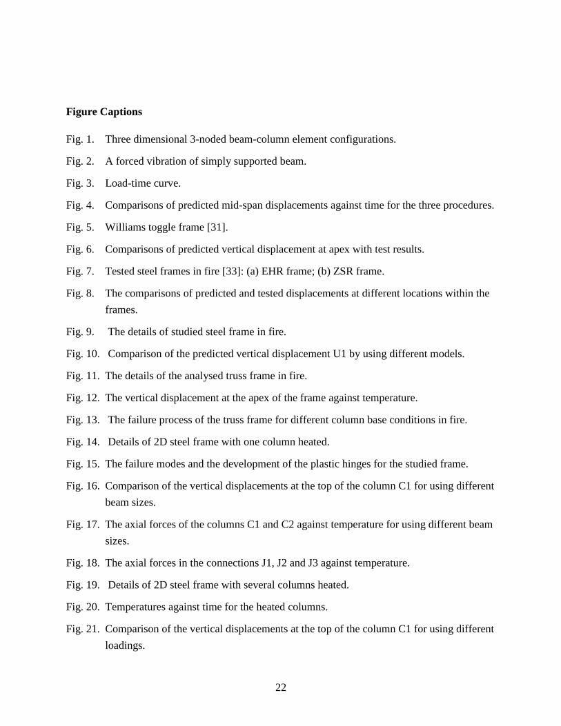
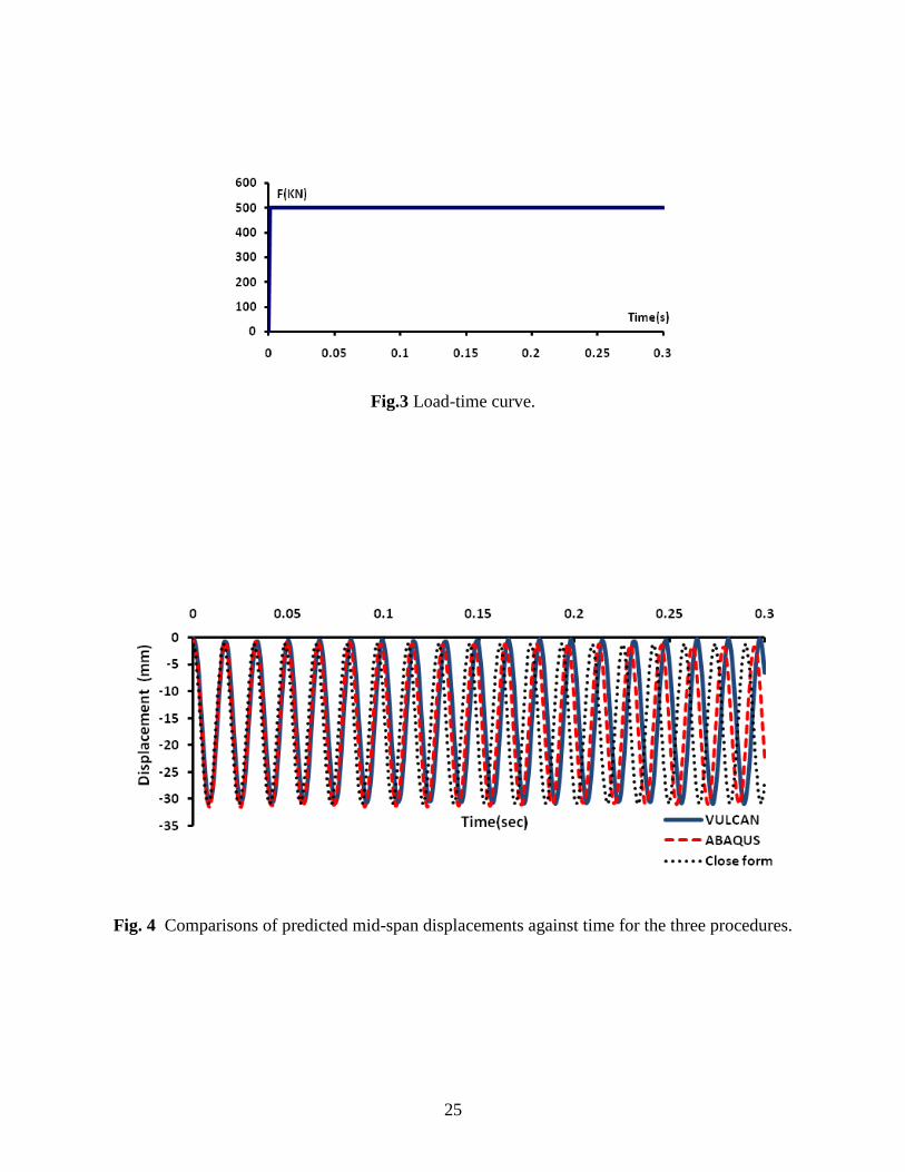
A forced vibration of simply supported beam as shown in Fig. 2 was analyzed. A concentrated
load was applied at the mid-span of the beam with the time-force curve which is shown in Fig. 3.
The cross section of the beam as shown in the Fig. 2 was adopted. Linear elastic material
Page 11
11
properties with Young‘s modulus, , was assumed. Eight elements were used to
model this beam. In the analysis the time step was automatically estimated. The predicted mid-
span displacements against time are presented in Fig. 4 together with the results generated by
ABAQUS and Close-form solution which was based on the elastic vibration theory. It is evident
that the results by three methods are in good agreement.
3.2 Stability problem
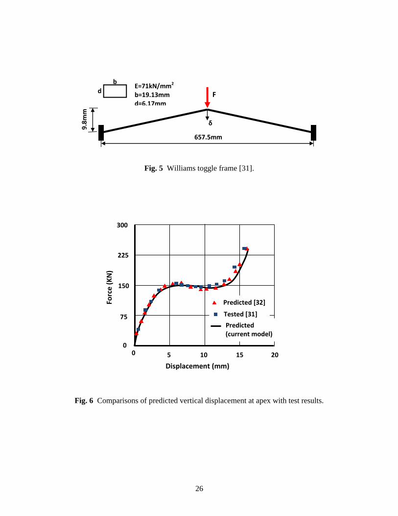
The Williams toggle frame [31], as shown in Fig. 5, has the structural behaviour of snap-through
buckling and its results have been used for verification of numerical solutions by many
researchers. The structure was assumed to be elastic and the material properties as indicated in
Fig. 5 were used. The fixed bases and rigid connection at apex were assumed. The concentrated
load at apex point of frame was increasing at a constant rate with time. At force level around
150N the snap-trough happened. The frame dropped rapidly and returned to the stable position
again later.
Fig. 6 shows the comparison of the load-displacement relationships obtained by the current
model and numerical results predicted by Yang and Chiou [32], together with the test results of
the Williams [31]. It is evident that the developed dynamic procedure can accurately handle this
problem.
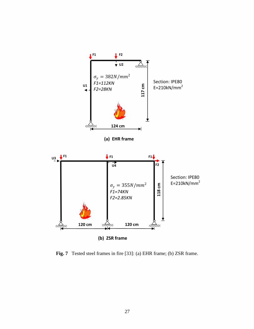
3.3 Steel frames tested in fire
The model has been validated using data from two groups of steel frames, tested by Rubert and
Schaumann [33] and subsequently investigated by other researchers [34, 35]. The structural
details are shown in Fig.7. The frames were all uniformly heated by ISO834 standard fire. The
L-shaped frame was designated as EHR, and the double-span one was designated as ZSR as
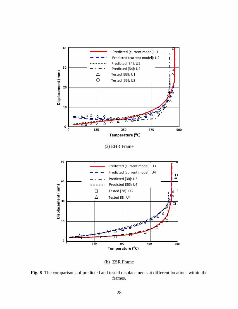
shown in Fig.7. All structural elements were made of IPE80 I-sections. The comparisons of
predicted displacements at different locations within the frames against the temperature are
shown in Fig. 8, together with the tested results [33] and other models' predictions [34, 35]. It
can be seen that the results generated by the current model agreed well with the tested data and
the predictions from other models.
3.4 Instability problem in fire
Page 12
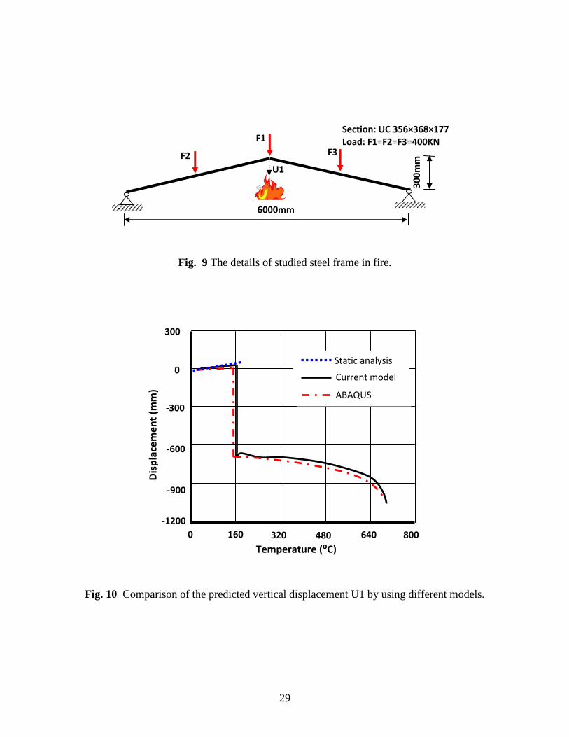
12
To validate the combined static-dynamic procedures developed, the simple frame as shown in
Fig. 9 has been investigated under ISO843 fire. The frame was also analyzed using the
commercial software ABAQUS/Standard to validate the current model. In this case implicit
integration was used in the ABAQUS full dynamic model. In the current procedure, the dynamic
analysis is switched on when the static analysis terminates as the instability of frame takes place;
then when the re-stable position is regained, the static procedure is restarted to carry on the
analysis. As indicated in Fig. 10, results generated by the current model agree well with the
predictions from ABAQUS. It is evident that current combined procedure is capable to trace the
behaviour of structure after local failure (snap-through, etc.) occurs and the analysis can be
continued up to the total failure of structure.
For considering the computational efficiency, it is difficult to make a direct comparison between
the different computer programs due to the different FE formulations adopted in the programs.
Therefore, above case has been analysed again by using full dynamic procedure developed in
this paper. In full dynamic analysis the computing time needed is proportional to fire duration.
Hence, if the real fire time, such as 60 min, is adopted for the analysis the massive computing
time is required to finish the modelling. However, it is often possible to scale the real time to a
very small equivalent time period if the response of the structure in fire remains basically
static. In order to save the computational time, the 60-min standard fire is scaled down to 20s for
full dynamic simulation. Almost identical results were produced for both full dynamic and
combined static-dynamic analyses. For this case the computing times for full dynamic and
combined static-dynamic procedures were 15 min and 60 min, respectively by using the same
computer. This indicates that the computational efficiency is improved significantly by suing
current combined static-dynamic procedure.
4. Case studies
In order to demonstrate the capability of the developed procedure a series parametric analyses
was conducted. Firstly, a uniformly heated latticed frame was modelled. Followed, a 2D three
stores with 4 bays steel frame has been investigated.
4.1 Truss frame in fire
Page 13
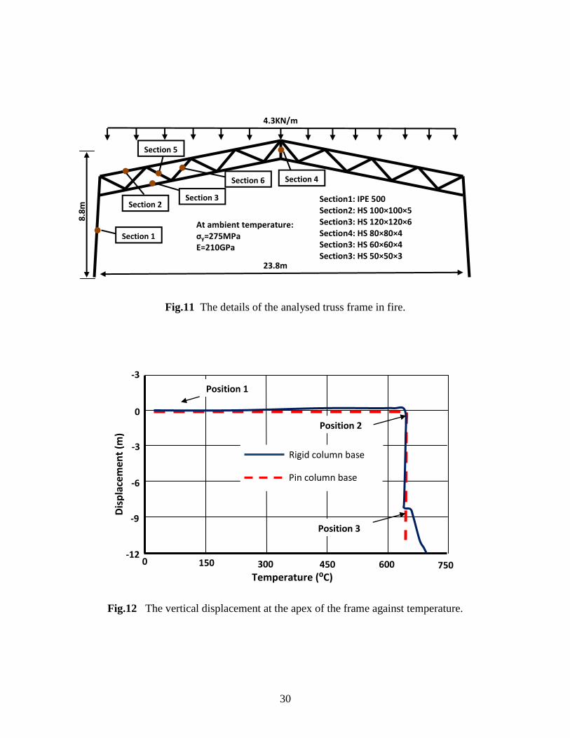
13
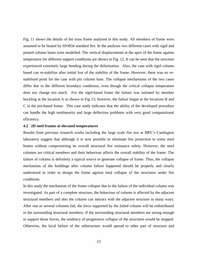
Fig. 11 shows the details of the truss frame analysed in this study. All members of frame were
assumed to be heated by ISO834 standard fire. In the analyses two different cases with rigid and
pinned column bases were modelled. The vertical displacements at the apex of the frame against
temperature for different support conditions are shown in Fig. 12. It can be seen that the structure
experienced extremely large bending during the deformation. Also, the case with rigid column
based can re-stabilize after initial lost of the stability of the frame. However, there was no re-
stabilised point for the case with pin column base. The collapse mechanisms of the two cases
differ due to the different boundary conditions, even though the critical collapse temperature
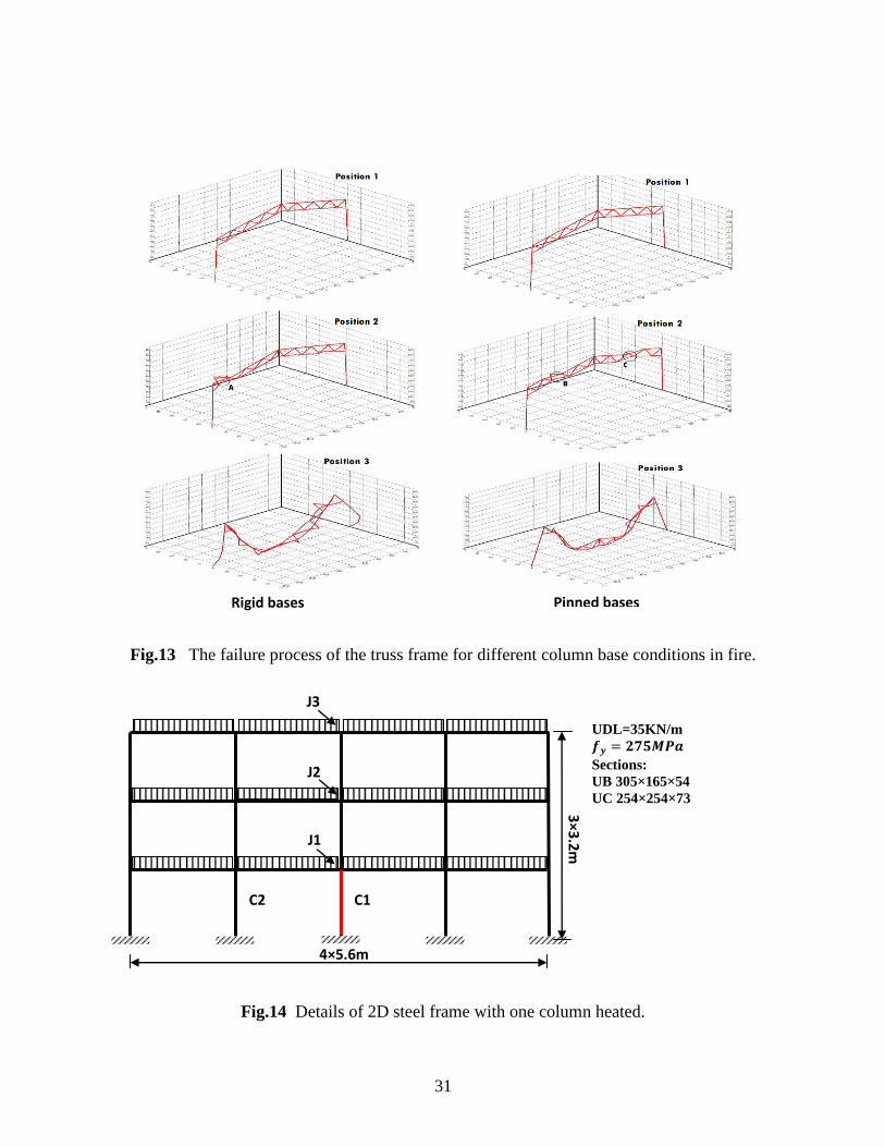
does not change too much. For the rigid-based frame the failure was initiated by member
buckling at the location A as shown in Fig 13; however, the failure began at the locations B and
C in the pin-based frame. This case study indicates that the ability of the developed procedure
can handle the high nonlinearity and large deflection problems with very good computational
efficiency.
4.2 2D steel frames at elevated temperatures
Results from previous research works including the large scale fire test at BRE‘s Cardington
laboratory suggest that although it is now possible to eliminate fire protection to some steel
beams without compromising its overall structural fire resistance safety. However, the steel
columns are critical members and their behaviour affects the overall stability of the frame. The
failure of column is definitely a typical source to generate collapse of frame. Thus, the collapse
mechanism of the buildings after column failure happened should be properly and clearly
understood in order to design the frame against total collapse of the structures under fire
conditions.
In this study the mechanism of the frame collapse due to the failure of the individual column was
investigated. As part of a complete structure, the behaviour of column is affected by the adjacent
structural members and also the column can interact with the adjacent structure in many ways.
After one or several columns fail, the force supported by the failed column will be redistributed
to the surrounding structural members. If the surrounding structural members are strong enough
to support those forces, the tendency of progressive collapse of the structures would be stopped.
Otherwise, the local failure of the substructure would spread to other part of structure and
Page 14
14
generate global collapse of the buildings. The study conducted here demonstrates the robustness
of the current combined static-dynamic procedure.
4.2.1 One column failure
A preliminary study of the frame with only one column heated to failure was carried out. It
gives fundamental insight of the loading redistribution mechanism and the members' interaction
within a steel frame. As shown in Fig. 14, a 3 story and 4 bay frames with UB 305×165×54
beam section and UC 254×254×73 column section was analyzed. The middle column C1 was
assumed to be heated by standard fire and the rest of the frame remained as ambient temperature.
European steel profiles of S235 steel grade was adopted and all beam-to-column connections
were considered to be rigid.
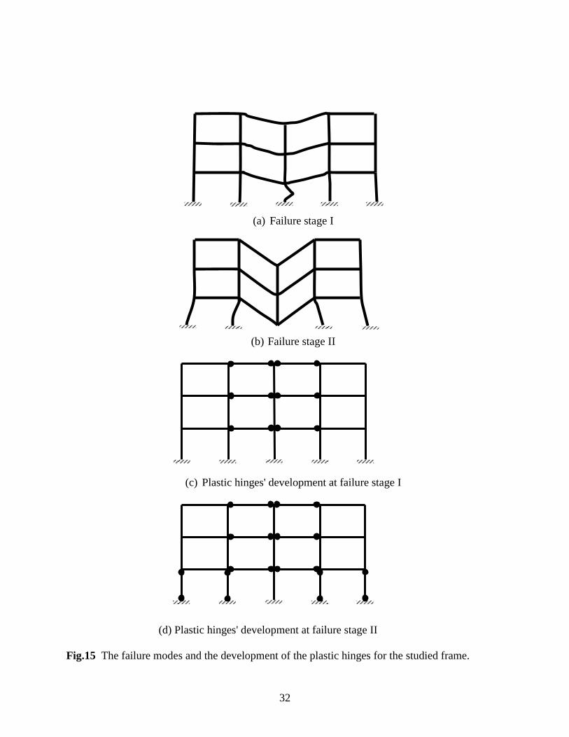
In the column C1 as the temperature rising, additional compression force was generated due to
the thermal expansion and the restraint provided by the surrounding cool structure. The material
strength of the steel was also degraded as temperature elevating. When the compression force
within the column exceeded the buckling load of the column C1, the buckle of the column took
place. After the buckle of the column the loads supported by the column C1 were re-distributed
to the adjacent remaining structural members. Fig. 15 shows the failure mode of the frame
studied and the development of the plastic hinges at the different stages.
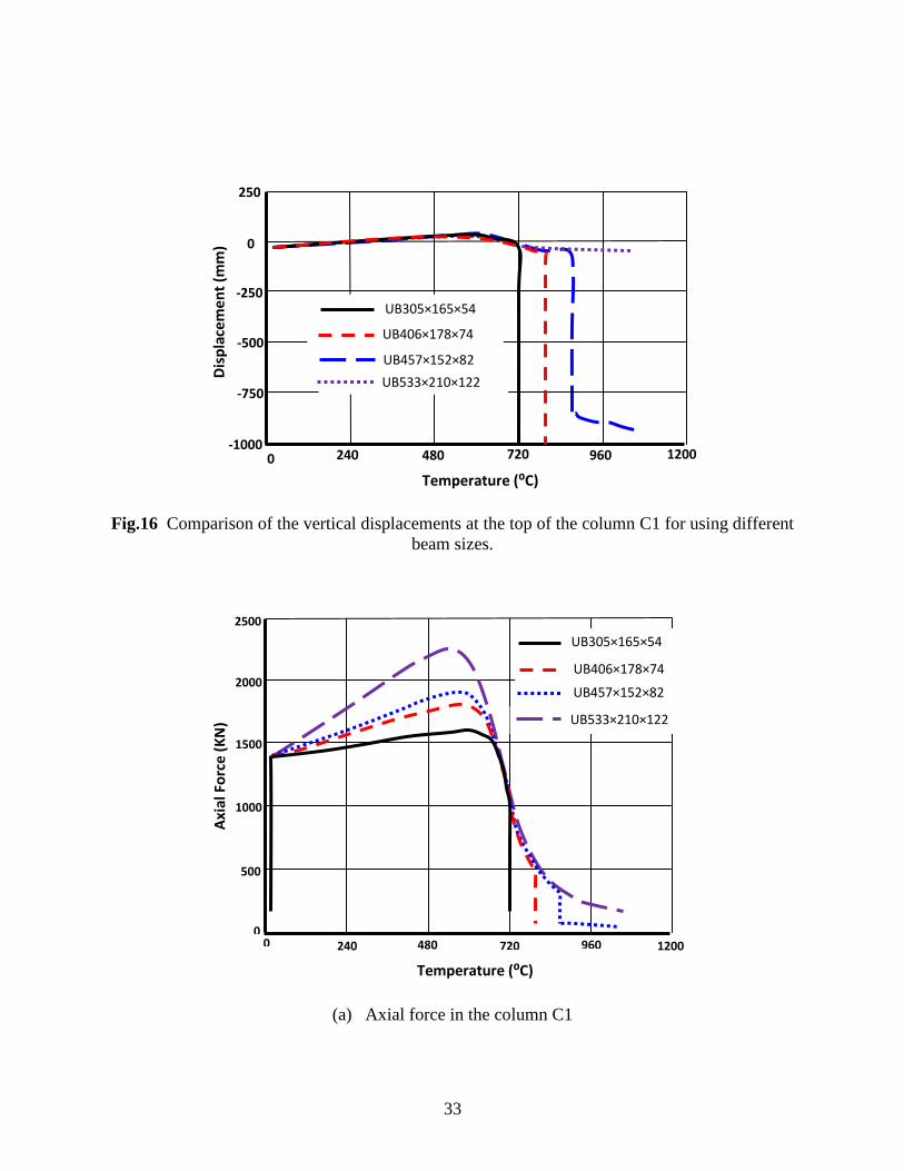
It is clear that the restraints to the column are mainly provided by the beams above the heated
column. In order to investigate the influence of the restraints on the columns to the frame
behaviour, the analyses were repeated by using different beam sections for the frame. The
vertical displacements at the top of the heated column with different beam section sizes are
shown in Fig. 16. Since different beam sections provide different stiffness and strength, hence
the beam section not only influences the critical temperature of column but also affect the
loading sharing mechanism of the frame. Fig. 17 shows the axial forces of the columns C1 and
C2 against temperature for using different beam sizes. Form the Fig. 17(a) it is clear that at the
same temperature level the big size of the beam generated lager additional compressive force in
the column C1. Therefore, the temperature level at which the column C1 starts to buckle is lower
for the large beam compared to the small beam. However, due to the rigid connection assumed
between the beam and column when the column C1 gradually lose it strength the beam behaves
Page 15
15
like a continue beam over the column C1. Hence, big beam can resist more bending moment
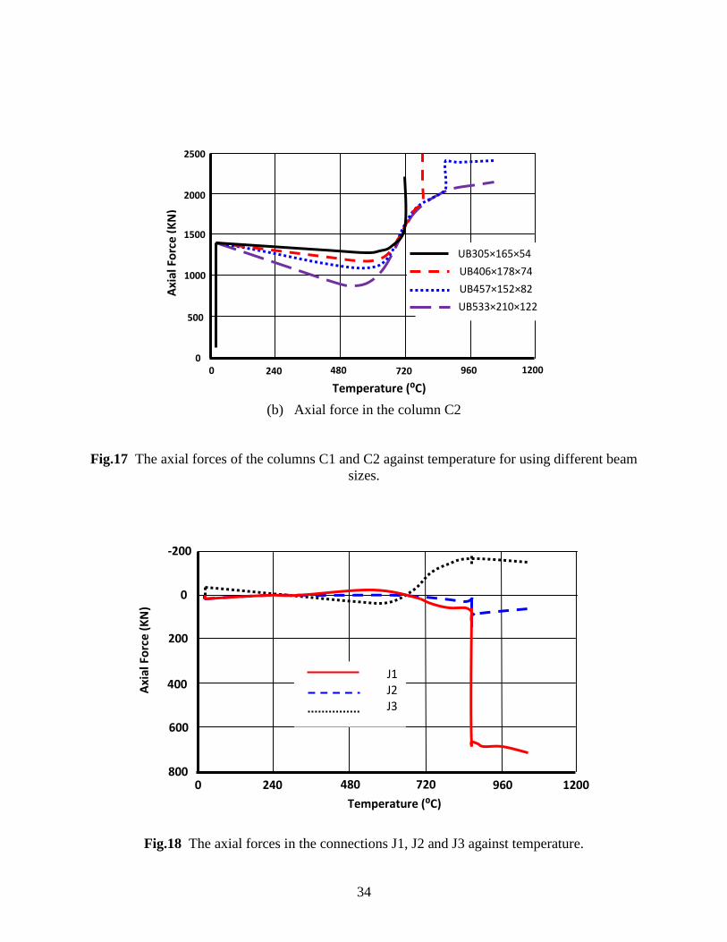
which is resulted due to the losing support capacity of the column C1. Fig. 17(b) shows the
different vertical loads transferred to the column C2 for different beam sizes. It is clear that after
the heated column C1 fails, the force taken by the column was redistributed. Hence, the axial
force acting on the column C2 increased. Also, using bigger beam section increases the
possibility of re-stabilization after the failure of the column.
The failure process of the frame as shown in Figs. 15(c) and (d) indicates that the plastic hinges
firstly generate in the middle bay; then spread to the edge bays. With increasing the size of the
beam section, the lateral stiffness of edge span is getting stronger. When the lateral stiffness is
big enough to hold the catenary force generated in the beam, the frame can be re-stabilized
eventually and failure stage II disappears. It is evident that increasing beam section can prevent
the frame from totally collapse when one column fails. Also the lateral support of the frame can
enhance the capacity of the frame to avoid the progressive collapse.
The force in joints connecting to the failed column is another interesting topic. As shown in
Fig. 18, the axial forces of connections change after column failure. That is because the failure of
middle column C1 would generate large deformation of beam, and then catenary action would
developed in the connected beams to hold the redistributed force. As shown in Fig.18, the force
in connection J1 in the same floor as failed column (see Fig. 14) changes significantly from
80KN to 680KN after the column C1 failed. This means that the catenary action is significantly
developed in the beams which connect to the failed column. The axial forces in the connections
J2 and J3 were also changed as shown in the figure. However, compared to the connection J1
these changes are insignificant. Therefore, for the design with the purpose of preventing frame
collapse, the connections in the same floor with the failed column should be under specially
attention.
4.2.2 Progressive column failure
In a real fire, several columns can be heated at the same time. When one column fails as a source
of collapse, the other columns would be more vulnerable because their strength degrades as the
fire develops. In this case, the columns will fail progressively, which will induce the total
collapse of the frame. As shown in Fig. 19, a 4 story- 4 bay frames was considered in this case
Page 16
16
study. All columns in the ground floor were heated by standard fire, but the middle column C1
had higher temperature (300ºC higher) so this column was the source column of collapse. The
temperature-time curves of the heated columns are shown in Fig.20. The behaviour of frame
under this scenario has been investigated and influences of different parameters were
investigated.
Influence of the loadings
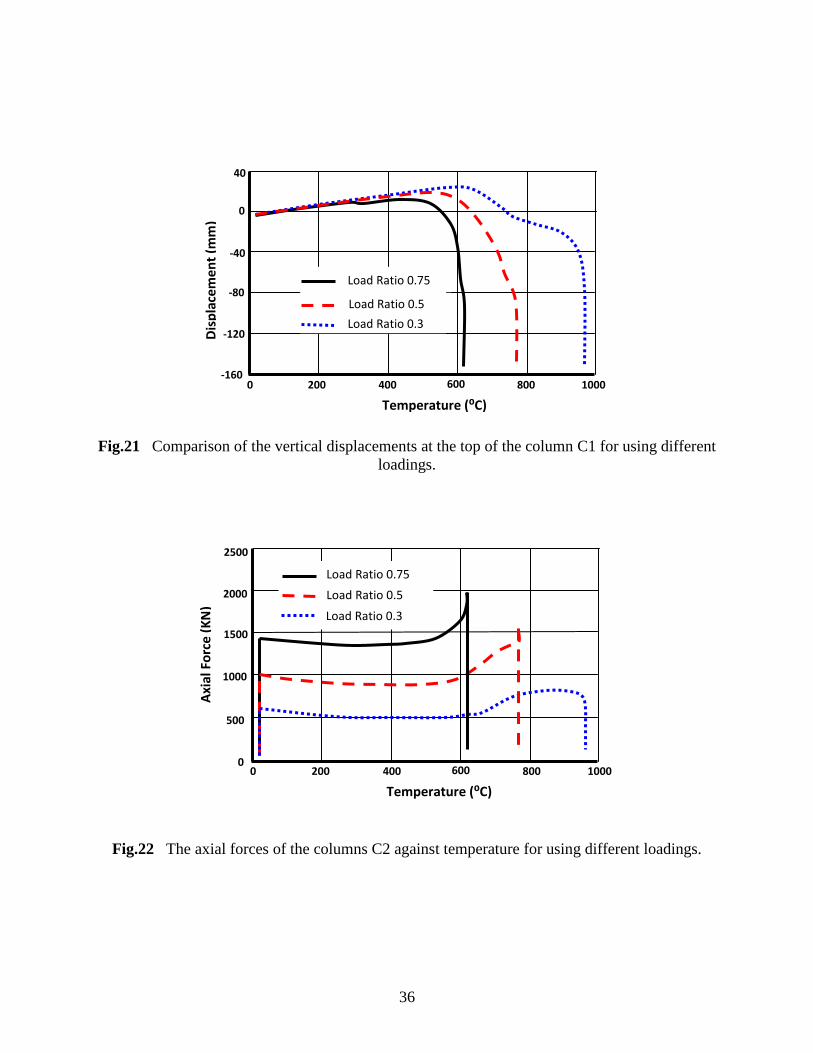
Frame analyses with different loading ratios of column (0.3, 0.5 and 0.73) were carried out. With
increasing loading ratio, the failure temperature of column decrease (see Fig. 21). There was no
sign of re-stabilization for these three loading ratios. Fig. 22 shows the axial forces of the
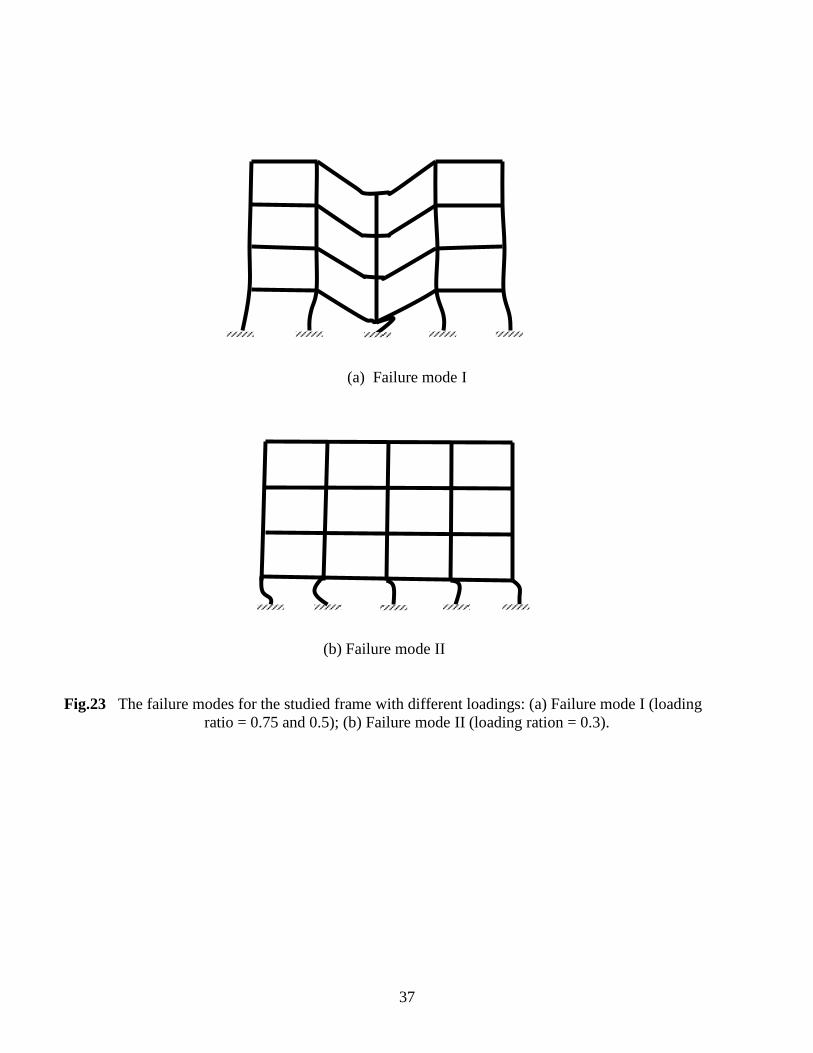
columns C2 against temperature for using different loadings. As shown in Fig. 23 the collapse
mechanism of the frame changes with the loading ratio. For higher loading ratios (see Fig. 23(a)),
the source column C1 buckled at relative low temperature, in which the rest columns did not
buckle, although they were heated. The total collapse of frame (failure mode I) in this case was
due to the lack of lateral support. With lower loading ratio, the frame could stand for more time
with higher failure temperature. However, when the source column C1 failed, then the loads
were transferred to the other columns. Due to the other columns were heated as well hence the
buckling took place in all rest columns. The failure mode of this case was presented in Fig. 23(b).
It can be seen that the failure mode II of the frame is more destructive compared to the failure
mode I.
Influence of beam sections
The analyses conducted in Section 4.2.1 indicate that the different collapse mechanism of the
frame could be generated by using different beam sections. Hence, three beam sections of
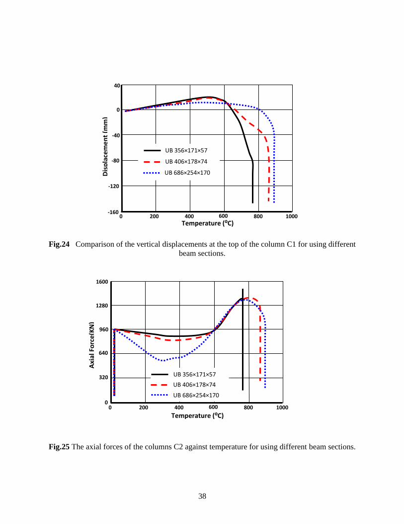
UB356×171×57 (UB1), UB406×178×74 (UB2) and UB686×254×170(UB3) were employed in
this study. Fig. 24 presents the comparison of the vertical displacements at the top of the column
C1 for using different beam sections. It is clear that the bigger beam section which can provides
stiffer lateral restraints could make the frame stood up longer time with higher failure
temperature. Fig. 25 shows the axial forces of the columns C2 against temperature for using
Page 17
17
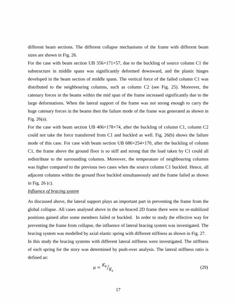
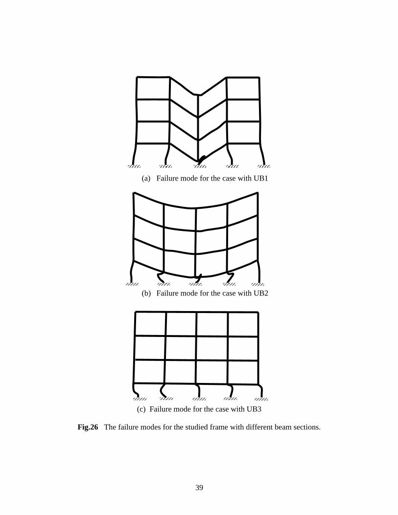
different beam sections. The different collapse mechanisms of the frame with different beam
sizes are shown in Fig. 26.
For the case with beam section UB 356×171×57, due to the buckling of source column C1 the
substructure in middle spans was significantly deformed downward, and the plastic hinges
developed in the beam section of middle spans. The vertical force of the failed column C1 was
distributed to the neighbouring columns, such as column C2 (see Fig. 25). Moreover, the
catenary forces in the beams within the mid span of the frame increased significantly due to the
large deformations. When the lateral support of the frame was not strong enough to carry the
huge catenary forces in the beams then the failure mode of the frame was generated as shown in
Fig. 26(a).
For the case with beam section UB 406×178×74, after the buckling of column C1, column C2
could not take the force transferred from C1 and buckled as well. Fig. 26(b) shows the failure
mode of this case. For case with beam section UB 686×254×170, after the buckling of column
C1, the frame above the ground floor is so stiff and strong that the load taken by C1 could all
redistribute to the surrounding columns. Moreover, the temperature of neighbouring columns
was higher compared to the previous two cases when the source column C1 buckled. Hence, all
adjacent columns within the ground floor buckled simultaneously and the frame failed as shown
in Fig. 26 (c).
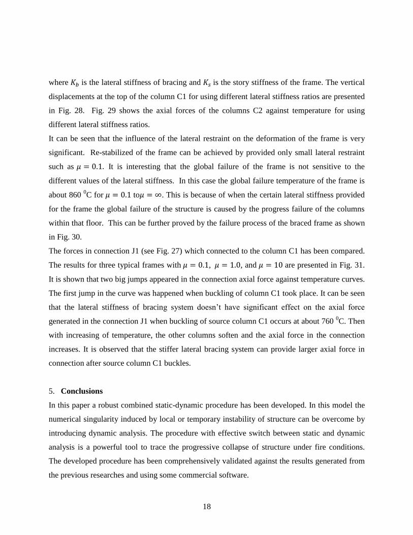
Influence of bracing system
As discussed above, the lateral support plays an important part in preventing the frame from the
global collapse. All cases analysed above in the un-braced 2D frame there were no re-stabilized
positions gained after some members failed or buckled. In order to study the effective way for
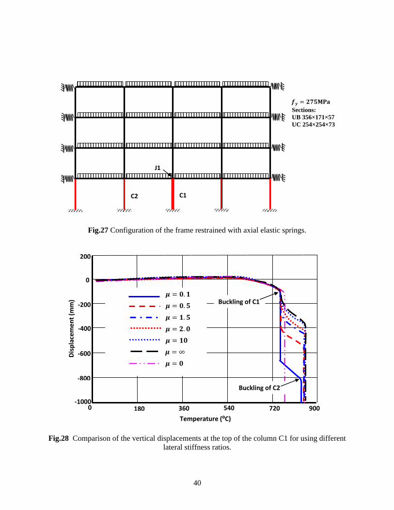
preventing the frame from collapse, the influence of lateral bracing system was investigated. The
bracing system was modelled by axial elastic spring with different stiffness as shown in Fig. 27.
In this study the bracing systems with different lateral stiffness were investigated. The stiffness
of each spring for the story was determined by push-over analysis. The lateral stiffness ratio is
defined as:
⁄ (29)
Page 18
18
where is the lateral stiffness of bracing and is the story stiffness of the frame. The vertical
displacements at the top of the column C1 for using different lateral stiffness ratios are presented
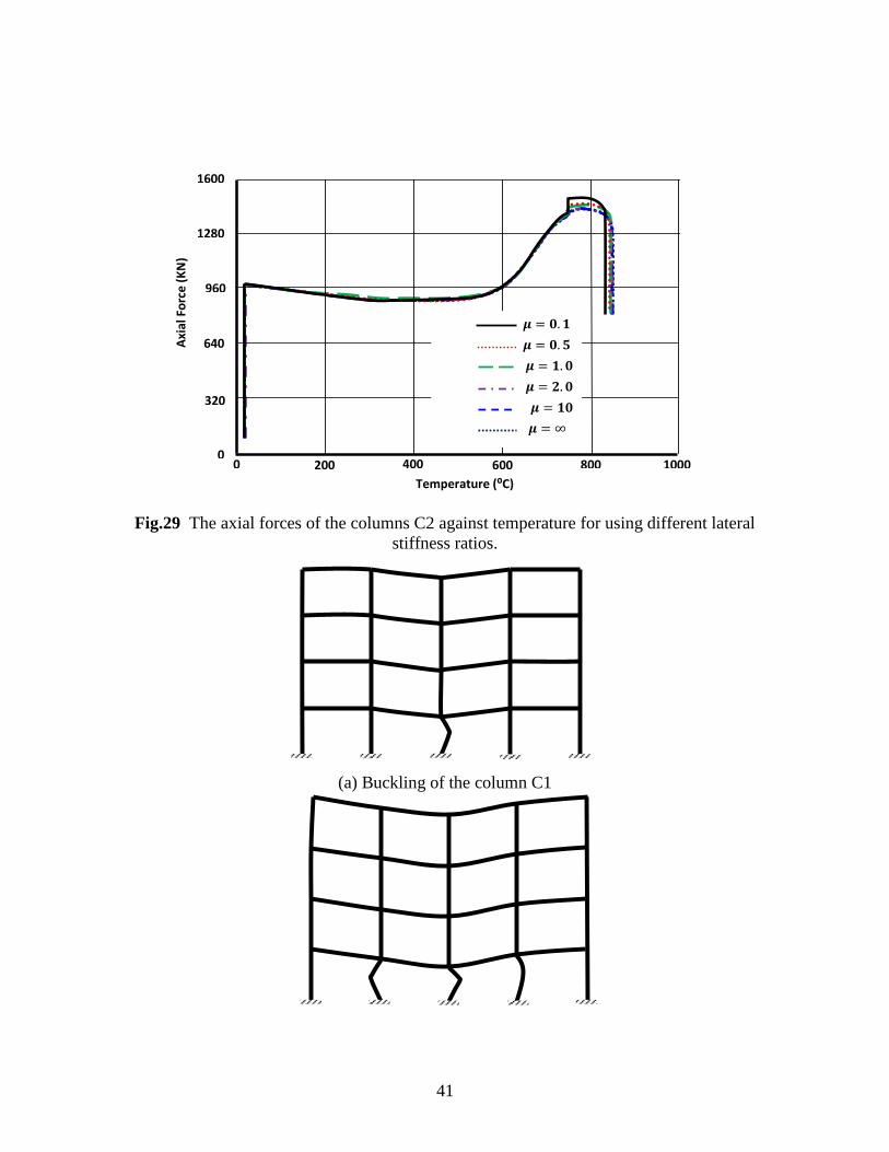
in Fig. 28. Fig. 29 shows the axial forces of the columns C2 against temperature for using
different lateral stiffness ratios.
It can be seen that the influence of the lateral restraint on the deformation of the frame is very
significant. Re-stabilized of the frame can be achieved by provided only small lateral restraint
such as It is interesting that the global failure of the frame is not sensitive to the
different values of the lateral stiffness. In this case the global failure temperature of the frame is
about 860 0C for to . This is because of when the certain lateral stiffness provided
for the frame the global failure of the structure is caused by the progress failure of the columns
within that floor. This can be further proved by the failure process of the braced frame as shown
in Fig. 30.
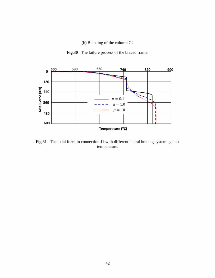
The forces in connection J1 (see Fig. 27) which connected to the column C1 has been compared.
The results for three typical frames with , , and are presented in Fig. 31.
It is shown that two big jumps appeared in the connection axial force against temperature curves.
The first jump in the curve was happened when buckling of column C1 took place. It can be seen
that the lateral stiffness of bracing system doesn‘t have significant effect on the axial force
generated in the connection J1 when buckling of source column C1 occurs at about 760 0C. Then
with increasing of temperature, the other columns soften and the axial force in the connection
increases. It is observed that the stiffer lateral bracing system can provide larger axial force in
connection after source column C1 buckles.
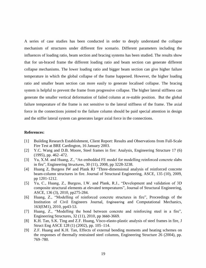
5. Conclusions
In this paper a robust combined static-dynamic procedure has been developed. In this model the
numerical singularity induced by local or temporary instability of structure can be overcome by
introducing dynamic analysis. The procedure with effective switch between static and dynamic
analysis is a powerful tool to trace the progressive collapse of structure under fire conditions.
The developed procedure has been comprehensively validated against the results generated from
the previous researches and using some commercial software.
Page 19
19
A series of case studies has been conducted in order to deeply understand the collapse
mechanism of structures under different fire scenario. Different parameters including the
influences of loading ratio, beam section and bracing systems has been studied. The results show
that for un-braced frame the different loading ratio and beam section can generate different
collapse mechanisms. The lower loading ratio and bigger beam section can give higher failure
temperature in which the global collapse of the frame happened. However, the higher loading
ratio and smaller beam section can more easily to generate localised collapse. The bracing
system is helpful to prevent the frame from progressive collapse. The higher lateral stiffness can
generate the smaller vertical deformation of failed column at re-stable position. But the global
failure temperature of the frame is not sensitive to the lateral stiffness of the frame. The axial
force in the connections jointed to the failure column should be paid special attention in design
and the stiffer lateral system can generates larger axial force in the connections.
References:
[1] Building Research Establishment, Client Report: Results and Observations from Full-Scale
Fire Test at BRE Cardington, 16 January 2003.
[2] Y.C. Wang and D.B. Moore, Steel frames in fire: Analysis, Engineering Structure 17 (6)
(1995), pp. 462–472.
[3] Yu, X.M. and Huang, Z., ―An embedded FE model for modelling reinforced concrete slabs
in fire‖, Engineering Structures, 30 (11), 2008, pp 3228-3238.
[4] Huang Z, Burgess IW and Plank RJ "Three-dimensional analysis of reinforced concrete
beam-column structures in fire. Journal of Structural Engineering, ASCE, 135 (10), 2009,
pp 1201-1212.
[5] Yu, C., Huang, Z., Burgess, I.W. and Plank, R.J., ―Development and validation of 3D
composite structural elements at elevated temperatures‖, Journal of Structural Engineering,
ASCE, 136 (3), 2010, pp275-284.
[6] Huang, Z., ―Modelling of reinforced concrete structures in fire‖, Proceedings of the
Institution of Civil Engineers Journal, Engineering and Computational Mechanics,
163(EM1), 2010, pp43-53.
[7] Huang, Z., ―Modelling the bond between concrete and reinforcing steel in a fire‖,
Engineering Structures, 32 (11), 2010, pp 3660-3669.
[8] K.H. Tan, S.K. Ting and Z.F. Huang, Visco-elasto-plastic analysis of steel frames in fire, J
Struct Eng ASCE 128 (1) (2002), pp. 105–114.
[9] Z.F. Huang and K.H. Tan, Effects of external bending moments and heating schemes on
the responses of thermally restrained steel columns, Engineering Structure 26 (2004), pp.
769–780.
Page 20
20
[10] Z.F. Huang and K.H. Tan, Structural responses of axially restrained steel beams with
semirigid moment connection in fire, J Struct Eng ASCE 131 (4) (2005), pp. 541–551.
[11] Z.F. Huang, K.H. Tan and S.K. Ting, Heating rate and boundary restraint effects on fire
resistance of steel columns with creep, Engineering Structure 28 (2006), pp. 805–817.
[12] Franssen JM, Kodur VK, Mason J. User‘s manual for SAFIR 2001: A computer program
for analysis of structures submitted to the fire. Belgium University of Liege, 2002.
[13] R. Becker, Structural behaviour of simple steel structures with non-uniform longitudinal
temperature distributions under fire conditions, Fire Safety J 37 (2002), pp. 495–515.
[14] V. Souza Junior and G.J. Creus, Simplified elastoplastic analysis of general frames on fire,
Engineering Structure 29 (2007), pp. 511–518.
[15] A. Buchanan, P. Moss, J. Seputro and R. Welsh, The effect of stress–strain relationships on
the fire performance of steel beams, Engineering Structure 26 (2004), pp. 1505–1515.
[16] A.M. Sanad, J.M. Rotter, A.S. Usmani and M.A. O‘Connor, Composite beams in large
buildings under fire: Numerical modelling and structural behaviour, Fire Safety J 35 (3)
(2000), pp. 165–188.
[17] Y.Z. Yin and Y.C. Wang, A numerical study of large deflection behaviour of restrained
steel beams at elevated temperatures, J Construct Steel Res 60 (2004), pp. 1029–1047.
[18] H. Chen and J.Y.R. Liew, Explosion and fire analysis of steel frames using mixed element
approach, Journal of Engineering Mechanics ASCE 131 (6) (2005), pp. 606–616.
[19] K.T. Ng and L. Gardner, Buckling of stainless steel columns and beams in fire,
Engineering Structure 29 (2007), pp. 711–730.
[20] J. Chen and B. Young, Cold-formed steel lipped channel columns at elevated temperatures,
Engineering Structure 29 (2007), pp. 2445–2456.
[21] J.B.P. Lim and B. Young, Effects of elevated temperatures on bolted moment-connections
between cold-formed steel members, Engineering Structure 29 (2007), pp. 2419–2427.
[22] J.A. El-Rimawi, I.W. Burgess and R.J. Plank, Studies of the behavior of steel subframes
with semi-rigid connections in fire, J Construct Steel Res 49 (1999), pp. 83–98.
[23] J.C. Zhao, Application of the direct iteration method for non-linear analysis of steel frames
in fire, Fire Safety J 35 (2000), pp. 241–255.
[24] A. Landesmann, E.M. Batista and J.L.D. Alves, Implementation of advanced analysis
method for steel-framed structures under fire conditions, Fire Safety J 40 (2005), pp. 339–
366.
[25] Samuel Tan, Albolhassan Astaneh-Asl. Cable-based retrofit of steel building floors to
prevent progressive collapse. Berkeley: University of California; 2003.
[26] B.A. Izzuddin et al., Progressive collapse of multi-storey buildings due to sudden column
loss—Part I: Simplified assessment framework, Engineering Structures 30 (2008), pp.
1308–1318.
[27] .A. Izzuddin et al., Progressive collapse of multi-storey buildings due to sudden column
loss—Part II: Simplified assessment framework, Engineering Structures 30 (2008), pp.
1424–1438.
[28] J.Y.R. Liew, Survivability of steel frame structures subject to blast and fire, Journal of
Constructional Steel Research 64 (7–8) (2008), pp. 854–866.
Page 21
21
[29] K.H. Lien et al., Vector Form Intrinsic Finite Element analysis of nonlinear behavior of
steel structures exposed to fire. Engineering Structure 32 (2010), pp. 80–92.
[30] R. Vignjevic, A hybrid approach to the transient collapse analysis of thin walled
frameworks I. Comput. Methods Appl. Mech. Eng. 148 (1997), pp. 407–421.
[31] Williams, F.W. (1964). ―An Approach to the Non-linear Behavior of the Members of a
Rigid Jointed Plane Framework with Finite Deflections.‖ Quart. J. Mech. Appl.Math., Vol.
17, 451-469.
[32] Y.B. Yang and H.T. Chiou, Rigid body motion test for nonlinear analysis with beam
elements, ASCE J.Engrg. Mech. 113 (9) (1987) 1404-1419.
[33] Rubert and Schaumann Rubert A, Schaumann P. Structural steel and plane frame
assemblies under fire action. Fire Safety Journal 1986;10:173-84.
[34] K.H. Lien K H Lien, Y J Chiou. Vector form intrinsic finite element analysis of nonlinear
behaviour of steel structure exposed to fire. Engineering Structure. 32(2010) Pages 80 – 92.
[35] Ali Hosam M. Ali, Lateral displacement and collapse of single-story steel frames in
uncontrolled fires. Engineering structure. 26(2004) PP. 593-607.
Page 22
22
Figure Captions
Fig. 1. Three dimensional 3-noded beam-column element configurations.
Fig. 2. A forced vibration of simply supported beam.
Fig. 3. Load-time curve.
Fig. 4. Comparisons of predicted mid-span displacements against time for the three procedures.
Fig. 5. Williams toggle frame [31].
Fig. 6. Comparisons of predicted vertical displacement at apex with test results.
Fig. 7. Tested steel frames in fire [33]: (a) EHR frame; (b) ZSR frame.
Fig. 8. The comparisons of predicted and tested displacements at different locations within the
frames.
Fig. 9. The details of studied steel frame in fire.
Fig. 10. Comparison of the predicted vertical displacement U1 by using different models.
Fig. 11. The details of the analysed truss frame in fire.
Fig. 12. The vertical displacement at the apex of the frame against temperature.
Fig. 13. The failure process of the truss frame for different column base conditions in fire.
Fig. 14. Details of 2D steel frame with one column heated.
Fig. 15. The failure modes and the development of the plastic hinges for the studied frame.
Fig. 16. Comparison of the vertical displacements at the top of the column C1 for using different
beam sizes.
Fig. 17. The axial forces of the columns C1 and C2 against temperature for using different beam
sizes.
Fig. 18. The axial forces in the connections J1, J2 and J3 against temperature.
Fig. 19. Details of 2D steel frame with several columns heated.
Fig. 20. Temperatures against time for the heated columns.
Fig. 21. Comparison of the vertical displacements at the top of the column C1 for using different
loadings.
Page 23
23
Fig. 22. The axial forces of the columns C2 against temperature for using different loadings.
Fig. 23. The failure modes for the studied frame with different loadings: (a) Failure mode I
(loading ratio = 0.75 and 0.5); (b) Failure mode II (loading ration = 0.3).
Fig. 24. Comparison of the vertical displacements at the top of the column C1 for using different
beam sections.
Fig. 25. The axial forces of the columns C2 against temperature for using different beam
sections.
Fig. 26. The failure modes for the studied frame with different beam sections.
Fig. 27. Configuration of the frame restrained with axial elastic springs.
Fig. 28. Comparison of the vertical displacements at the top of the column C1 for using different
lateral stiffness ratios.
Fig. 29. The axial forces of the columns C2 against temperature for using different lateral
stiffness ratios.
Fig. 30. The failure process of the braced frame.
Fig. 31. The axial force in connection J1 with different lateral bracing system against
temperature.
Page 24
24
Fig.1 Three dimensional 3-noded beam-column element.
Fig.2 A simply supported beam for forced vibration test.
1
2
3
r
s
t x
y
z
s
t Beam centroidal axis
Reference axis
Vt
Segments
x’
y’
z’
Vr
Vs ak
bk
4m
F
320mm
200mm
20mm
20mm
Dimension Cross section
Page 25
25
Fig.3 Load-time curve.
Fig. 4 Comparisons of predicted mid-span displacements against time for the three procedures.
Page 26
26
Fig. 5 Williams toggle frame [31].
Fig. 6 Comparisons of predicted vertical displacement at apex with test results.
δ
657.5mm
9.8
mm
F
b
d E=71kN/mm2 b=19.13mm d=6.17mm
Displacement (mm)
5
75
10 15 20
0 0
150
225
300
Predicted [32]
Tested [31]
Predicted (current model)
Forc
e (
KN
)
Page 27
27
Fig. 7 Tested steel frames in fire [33]: (a) EHR frame; (b) ZSR frame.
U1
U2
F1 F2
124 cm
11
7 c
m
(a) EHR frame
𝜎 = 382 / 2
F1=112KN F2=28KN
Section: IPE80 E=210kN/mm2
120 cm 120 cm
11
8 c
m
U3
U4
F1 F1 F1
F2
(b) ZSR frame
𝜎 = 355 / 2
F1=74KN F2=2.85KN
Section: IPE80 E=210kN/mm2
Page 28
28
(a) EHR Frame
(b) ZSR Frame
Fig. 8 The comparisons of predicted and tested displacements at different locations within the
frames.
Predicted (current model): U1
Predicted (current model): U2
Predicted [34]: U1
Predicted [34]: U2
Tested [33]: U1
Tested [33]: U2
0 125 250 375 500 0
10
20
30
40
Temperature (⁰C)
Dis
pla
cem
en
t (m
m)
0 150 300 450 600 0
15
30
45
60
Temperature (⁰C)
Dis
pla
cem
en
t (m
m)
Predicted (current model): U3
Predicted (current model): U4
Predicted [30]: U3
Predicted [30]: U4
Tested [28]: U3
Tested [8]: U4
Page 29
29
Fig. 9 The details of studied steel frame in fire.
Fig. 10 Comparison of the predicted vertical displacement U1 by using different models.
F2
F1
F3
U1
6000mm
30
0m
m
Section: UC 356×368×177 Load: F1=F2=F3=400KN
160
-900
320 480 640
-1200
0
-600
-300
0
Temperature (⁰C)
Dis
pla
cem
en
t (m
m)
800
300
Current model
ABAQUS
Static analysis
Page 30
30
Fig.11 The details of the analysed truss frame in fire.
Fig.12 The vertical displacement at the apex of the frame against temperature.
Section 1
Section 2 Section 3
Section 6
Section 5
Section 4
4.3KN/m
8.8
m
23.8m
Section1: IPE 500 Section2: HS 100×100×5 Section3: HS 120×120×6 Section4: HS 80×80×4 Section3: HS 60×60×4 Section3: HS 50×50×3
At ambient temperature: σy=275MPa E=210GPa
150
-9
300 450 600 -12
0
-6
-3
0
Temperature (⁰C)
Dis
pla
cem
en
t (m
)
750
-3
Rigid column base
Pin column base
Position 1
Position 2
Position 3
Page 31
31
Fig.13 The failure process of the truss frame for different column base conditions in fire.
Fig.14 Details of 2D steel frame with one column heated.
Rigid bases Pinned bases
UDL=35KN/m
𝒇𝒚 = 𝟐𝟕𝟓 𝑷𝒂
Sections:
UB 305×165×54
UC 254×254×73
C1 C2
4×5.6m
3×
3.2
m
J1
J2
J3
Page 32
32
(a) Failure stage I
(b) Failure stage II
(c) Plastic hinges' development at failure stage I
(d) Plastic hinges' development at failure stage II
Fig.15 The failure modes and the development of the plastic hinges for the studied frame.
Page 33
33
Fig.16 Comparison of the vertical displacements at the top of the column C1 for using different
beam sizes.
(a) Axial force in the column C1
240
-750
480 720 960 -1000
0
-500
-250
0
Temperature (⁰C)
Dis
pla
cem
en
t (m
m)
250
UB305×165×54
UB406×178×74
UB457×152×82
UB533×210×122
1200
240
500
480 720 960 0 0
1000
1500
2000
Temperature (⁰C)
Axi
al F
orc
e (
KN
)
2500
UB305×165×54
UB406×178×74
UB457×152×82
UB533×210×122
1200
Page 34
34
(b) Axial force in the column C2
Fig.17 The axial forces of the columns C1 and C2 against temperature for using different beam
sizes.
Fig.18 The axial forces in the connections J1, J2 and J3 against temperature.
240
500
480 720 960 0
0
1000
1500
2000
Temperature (⁰C)
Axi
al F
orc
e (
KN
)
2500
UB305×165×54
UB406×178×74
UB457×152×82
UB533×210×122
1200
-200
0
200
400
600
800 0 240 480 720 960 1200
Axi
al F
orc
e (
KN
)
Temperature (⁰C)
J1 J2 J3
Page 35
35
Fig.19 Details of 2D steel frame with several columns heated.
Fig.20 Temperatures against time for the heated columns.
𝒇𝒚 = 𝟐𝟕𝟓 𝐏𝐚
Sections:
UB 356×171×57
UC 254×254×73
C1 C2
4×6m
4×3
.6m
0 1600 3200 4800 6400 8000
0
240
480
720
960
1200
C1 C2 and others
Tem
per
atu
re (ºC
)
Time (s)
Page 36
36
Fig.21 Comparison of the vertical displacements at the top of the column C1 for using different
loadings.
Fig.22 The axial forces of the columns C2 against temperature for using different loadings.
200 0 400 600 800 1000
40
0
-40
-80
-120
-160
Load Ratio 0.75
Load Ratio 0.5
Load Ratio 0.3
Temperature (⁰C)
Dis
pla
cem
en
t (m
m)
200 0 400 600 800 1000
2500
2000
1500
1000
500
0
Load Ratio 0.75
Load Ratio 0.5
Load Ratio 0.3
Temperature (⁰C)
Axi
al F
orc
e (
KN
)
Page 37
37
(a) Failure mode I
(b) Failure mode II
Fig.23 The failure modes for the studied frame with different loadings: (a) Failure mode I (loading
ratio = 0.75 and 0.5); (b) Failure mode II (loading ration = 0.3).
Page 38
38
Fig.24 Comparison of the vertical displacements at the top of the column C1 for using different
beam sections.
Fig.25 The axial forces of the columns C2 against temperature for using different beam sections.
200 0 400 600 800 1000
40
0
-40
-80
-120
-160
UB 356×171×57
Temperature (⁰C)
Dis
pla
cem
en
t (m
m)
UB 406×178×74
UB 686×254×170
200 0 400 600 800 1000
1600
1280
960
640
320
0
UB 356×171×57
Temperature (⁰C)
Axi
al F
orc
e(K
N)
UB 406×178×74
UB 686×254×170
Page 39
39
(a) Failure mode for the case with UB1
(b) Failure mode for the case with UB2
(c) Failure mode for the case with UB3
Fig.26 The failure modes for the studied frame with different beam sections.
Page 40
40
Fig.27 Configuration of the frame restrained with axial elastic springs.
Fig.28 Comparison of the vertical displacements at the top of the column C1 for using different
lateral stiffness ratios.
C1 C2
𝒇𝒚 = 𝟐𝟕𝟓 𝐏𝐚
Sections:
UB 356×171×57
UC 254×254×73
J1
180 0 360 540 720
0
-200
-400
-600
-800
-1000
Temperature (⁰C)
Dis
pla
cem
en
t (m
m)
200
𝝁 = 𝟎. 𝟏
𝝁 = 𝟎. 𝟓
𝝁 = 𝟏. 𝟓
𝝁 = 𝟐. 𝟎
𝝁 = 𝟏𝟎
𝝁 =
𝝁 = 𝟎
Buckling of C1
Buckling of C2
900
Page 41
41
Fig.29 The axial forces of the columns C2 against temperature for using different lateral
stiffness ratios.
(a) Buckling of the column C1
1600
1280
320
640
960
0 0 200 400 600 800 1000
𝝁 = 𝟎. 𝟏
𝝁 = 𝟎. 𝟓
𝝁 = 𝟏. 𝟎
𝝁 = 𝟐. 𝟎
𝝁 = 𝟏𝟎
𝝁 =
Temperature (⁰C)
Axi
al F
orc
e (
KN
)
Page 42
42
(b) Buckling of the column C2
Fig.30 The failure process of the braced frame.
Fig.31 The axial force in connection J1 with different lateral bracing system against
temperature.
0
120
240
360
480
600
500 580 660 740 820 900
Temperature (⁰C)
Axi
al F
orc
e (
KN
)
= 0.1
= 1.0
= 10
Page 43
43
Table 1 Flowchart for explicit time integration.
1. Initial conditions and initialization:
Set initial value of material state variables and 𝒖0𝑛 ��0
𝑛, compute mass matrix
M and initially estimate the time step.
2. Initialise the nodal internal force.
3. Compute the accelerations ��𝑖𝑛 (𝑴𝑛) (𝑸𝑖
𝑛 𝑭𝑖𝑛 𝑫𝑖
𝑛)
4. Time update: 𝑡𝑖 ⬚ 𝑡𝑖
⬚ 𝑡𝑖⬚; 𝑡𝑖
⬚ ( 𝑡𝑖⬚ 𝑡𝑖
⬚ )
5. First partial update nodal velocities: ��𝑖 𝑛 ��𝑖
𝑛 𝑡𝑖⬚��𝑖
𝑛
6. Enforce boundary conditions.
7. Update the nodal displacements: 𝒖𝑖 𝑛 𝒖𝑖
𝑛 𝑡𝑖 ⬚ ��𝑖
𝑛
8. Calculate the nodal internal forces.
9. Compute ��𝑖𝑛
10. Second partial update nodal velocities: ��𝑖𝑛 ��𝑖
𝑛 (𝑡𝑖 ⬚ 𝑡𝑖
⬚ )��𝑖 𝑛
11. Check energy balance at time step i+1
12. Adaptive check for variable time step.
13. Update counter: i=i+1
14. Output; if simulation not complete, go to 4.
Page 44
44
Table 2 Flowchart of the developed procedure
Read in model
Static Analysis with
Temperature Rising
Numerical Singularity?
Explicit Dynamic
Analysis
Re-stabilization?
Yes
No
No
Yes