Georgia Institute of Technology | Milwaukee School of Engineering | North Carolina A&T State University | Purdue University University of Illinois, Urbana-Champaign | University of Minnesota | Vanderbilt University Project 1J.1: Hydraulic Transmissions for Wind Energy Researchers: Biswaranjan Mohanty, Feng Wang, Brad Bohlmann, Mike Gust PI: Professor Kim A. Stelson Center for Compact and Efficient Fluid Power Department of Mechanical Engineering University of Minnesota FPIRC, Chicago, October 14-16, 2015
Transcript
Georgia Institute of Technology | Milwaukee School of Engineering | North Carolina A&T State University | Purdue University
University of Illinois, Urbana-Champaign | University of Minnesota | Vanderbilt University
Project 1J.1: Hydraulic Transmissions
for Wind Energy
Researchers: Biswaranjan Mohanty,
Feng Wang, Brad Bohlmann,
Mike Gust
PI: Professor Kim A. Stelson
Center for Compact and Efficient Fluid Power
Department of Mechanical Engineering
University of Minnesota
FPIRC, Chicago, October 14-16, 2015
2
Outline
1. Introduction
2. Research topics
Hydrostatic turbine control
Short-term energy storage
Hydro-mechanical transmission
3. Power regenerative wind turbine test platform
4. Conclusions
3
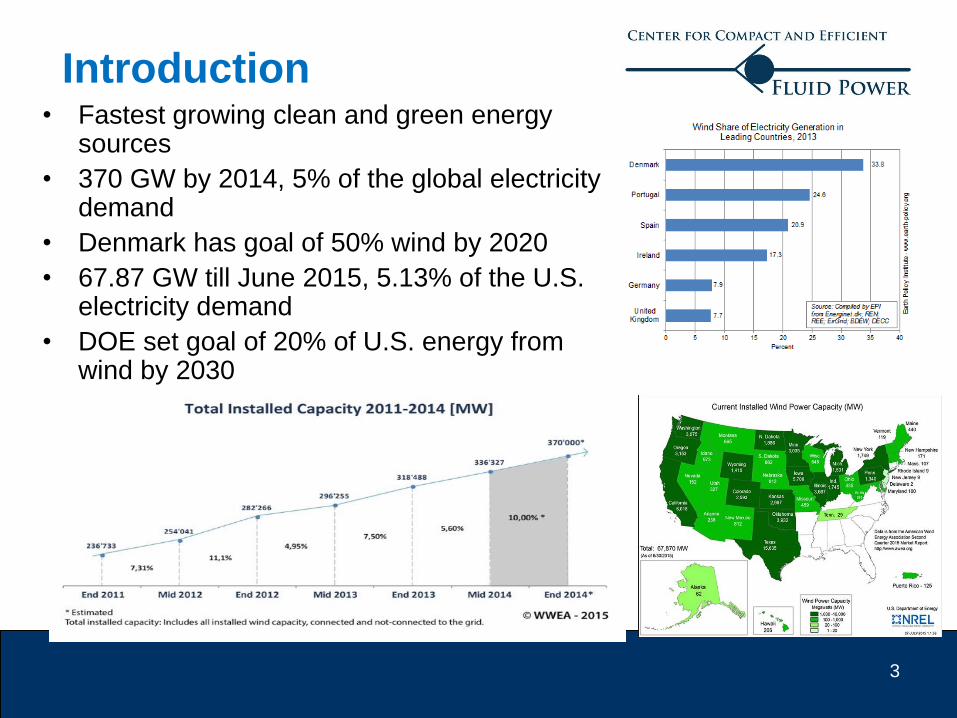
• Fastest growing clean and green energy sources
• 370 GW by 2014, 5% of the global electricity demand
• Denmark has goal of 50% wind by 2020
• 67.87 GW till June 2015, 5.13% of the U.S. electricity demand
• DOE set goal of 20% of U.S. energy from wind by 2030
Introduction
4
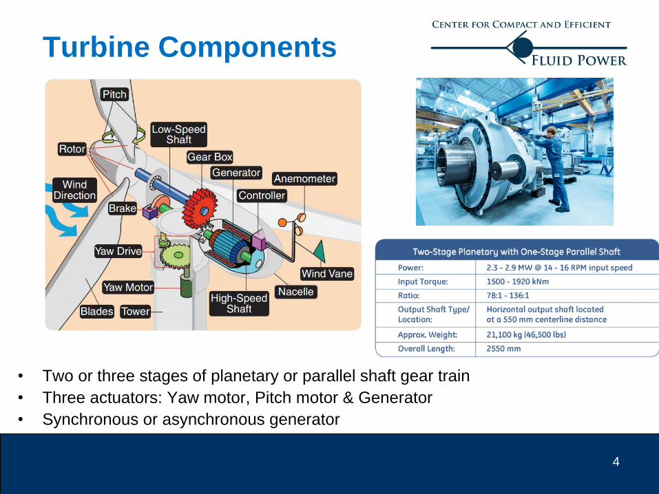
• Two or three stages of planetary or parallel shaft gear train
• Three actuators: Yaw motor, Pitch motor & Generator
• Synchronous or asynchronous generator
Turbine Components
5
Components reliability
WindStats Data
- 5,000 turbines from Denmark, 24,000 from Germany & 1,200 from Sweden
Electrical system has highest failure rate
Gear Box has longest downtime per failure
Drive train repairs are more expensive due to the crane costs.
6
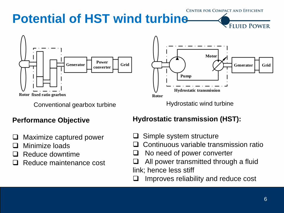
Hydrostatic transmission (HST):
Simple system structure
Continuous variable transmission ratio
No need of power converter
All power transmitted through a fluid
link; hence less stiff
Improves reliability and reduce cost
Conventional gearbox turbine
Rotor
GeneratorPower
converter
fixed ratio gearbox
Grid
Rotor
Hydrostatic transmission
Generator Grid
Pump
Motor
Hydrostatic wind turbine
Potential of HST wind turbine
Performance Objective
Maximize captured power
Minimize loads
Reduce downtime
Reduce maintenance cost
7
HST wind turbines
Core technology: Digital displacement technology by Artemis
Mitsubishi 7MW Sea Angel offshore turbine
1. ChapDrive (Norway)
2. Windera Power System (Florida)
3. WindSmart (Canada)
4. Mitsubishi Heavy Industry
93.5% peak efficiency from shaft-to-shaft, and
also very efficient in part load too
Aachen University IFAS 1 MW
HST wind power test stand
8
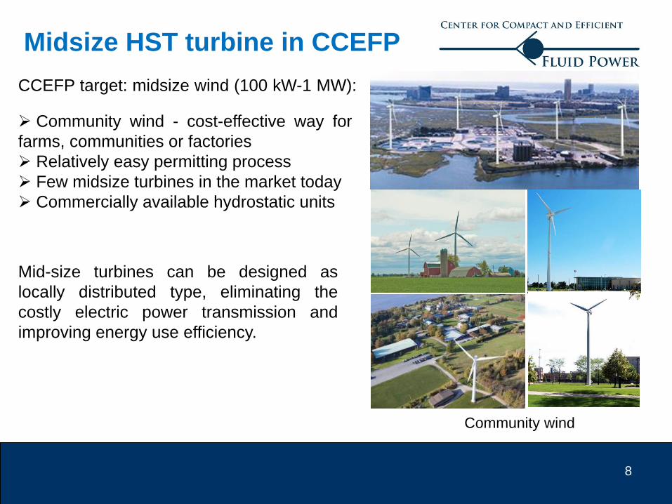
Midsize HST turbine in CCEFP
Mid-size turbines can be designed as
locally distributed type, eliminating the
costly electric power transmission and
improving energy use efficiency.
CCEFP target: midsize wind (100 kW-1 MW):
Community wind - cost-effective way for
farms, communities or factories
Relatively easy permitting process
Few midsize turbines in the market today
Commercially available hydrostatic units
Community wind
9
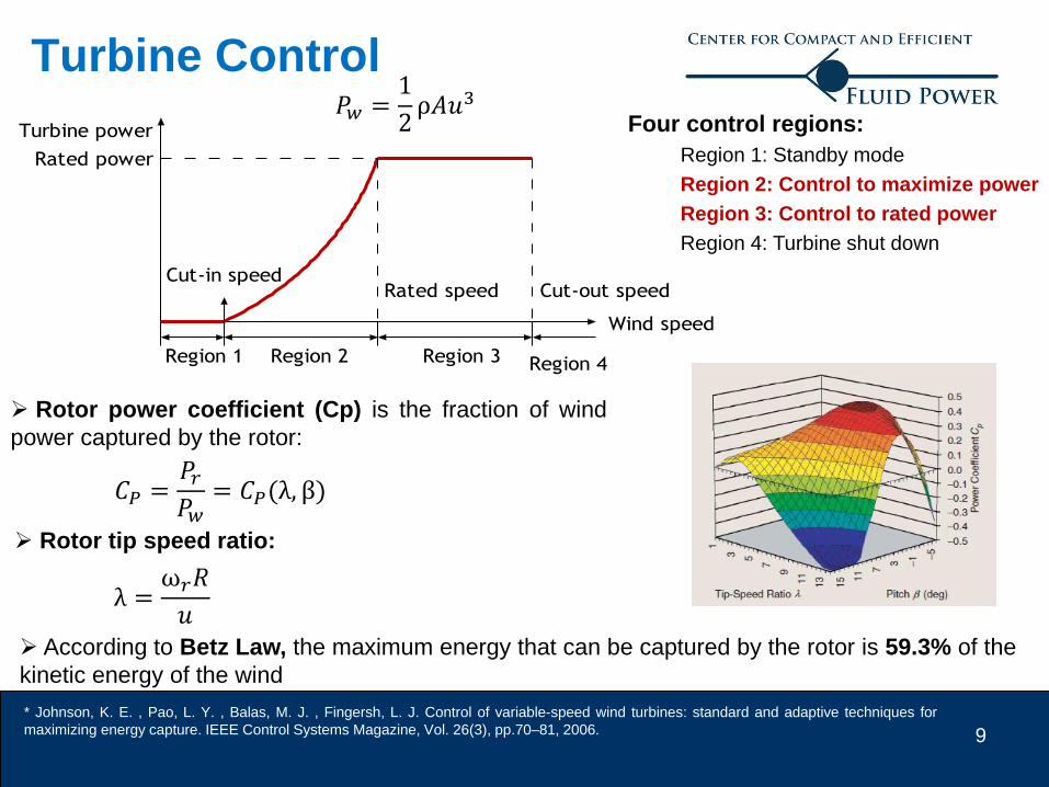
Turbine Control
Wind speed
Turbine power
Rated speed Cut-out speed
Region 1 Region 2 Region 3
Rated power
Cut-in speed
Region 4
Four control regions:
Region 1: Standby mode
Region 2: Control to maximize power
Region 3: Control to rated power
Region 4: Turbine shut down
Rotor power coefficient (Cp) is the fraction of wind
power captured by the rotor:
Rotor tip speed ratio:
𝐶𝑃 =𝑃𝑟𝑃𝑤
= 𝐶𝑃(λ, β)
λ =ω𝑟𝑅
𝑢
𝑃𝑤 =1
2ρ𝐴𝑢3
According to Betz Law, the maximum energy that can be captured by the rotor is 59.3% of the
kinetic energy of the wind
* Johnson, K. E. , Pao, L. Y. , Balas, M. J. , Fingersh, L. J. Control of variable-speed wind turbines: standard and adaptive techniques for
maximizing energy capture. IEEE Control Systems Magazine, Vol. 26(3), pp.70–81, 2006.
10
Torque control law - control rotor reaction
torque:
where the gain K is given by blade parameters.
Region 2 Control (Existing)
• Objective: Maximize power captured
• Strategy: Constant pitch angle β and use τ𝑔 to operate turbine at optimum point
τ𝑔 = τ𝑐 = 𝐾ω𝑟2
𝐾 =1
2ρ𝐴𝑅3
𝐶𝑝𝑚𝑎𝑥
λ∗3
Dynamics of the rotor
ω𝑟 =1
2𝐽ρ𝐴𝑅3ω𝑟
2(𝐶𝑝
λ3−
𝐶𝑝𝑚𝑎𝑥
λ∗3 ) u
142 4 6 8 10 12
0.3
0.4
0.5
0.2
0.1R
oto
rp
ow
er c
oeffic
ien
t
Tip speed ratio
pC
maxpC
*
Acceleration Deceleration
max
3 3
*
p pC C
max
3 3
*
p pC C
max
3 3
*
p pC C
Optimum point
The beauty of the kω2 law: bring the turbine to
optimal point only with rotor speed and it does not
require wind speed information.
11
HST turbine control in region 2
Control strategy
1. Use rotor speed to generate rotor reaction torque (pump torque) command (kω2 law)
2. Convert pump torque command to line pressure command
3. Track the line pressure by adjusting motor displacement through PI controller
Rotor
Hydrostatic transmission
Generator
Kω2 law
Torque/
pressure
conversion
torque
cmd
pressure
cmd PI
controller
Pressure
sensor
+-
motor
disp. cmd
p
c c
p
pD
HST turbine control scheme in region 2
where ηp is the pump mechanical
efficiency.
• F. Wang and K. A. Stelson, ‘Model predictive control for a mid-sized hydrostatic wind turbine’, 13th Scandinavian International Conference on
Fluid Power, SICFP2013, June 3-5, 2013, Linköping, Sweden, 2013.
Rotor reaction torque generated by the pump
The relationship between the
pump torque command and the
line pressure command:
To give accurate control, the pump
mechanical efficiency is estimated by
previewing the pump efficiency
map from the historical rotor speed
and line pressure data.
12
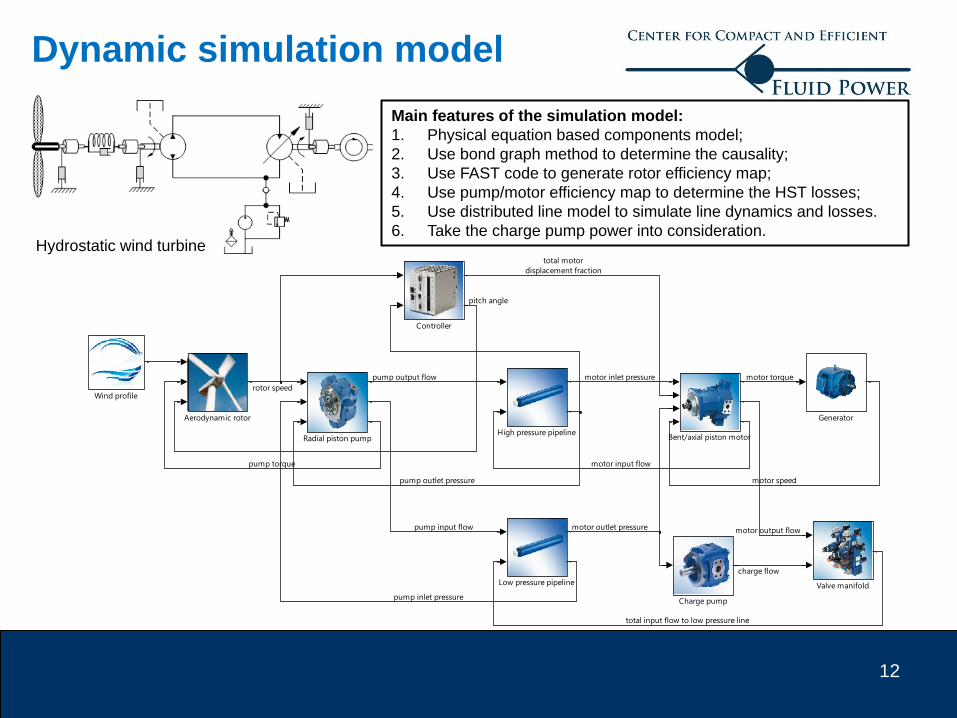
Dynamic simulation model
Main features of the simulation model:
1. Physical equation based components model;
2. Use bond graph method to determine the causality;
3. Use FAST code to generate rotor efficiency map;
4. Use pump/motor efficiency map to determine the HST losses;
5. Use distributed line model to simulate line dynamics and losses.
6. Take the charge pump power into consideration.Hydrostatic wind turbine
Wind profile
Valve manifold
Radial piston pump
Low pressure pipeline
High pressure pipeline
Generator
Controller
Charge pump
Bent/axial piston motor
Aerodynamic rotor
rotor speed
pump output flow
pump torque
pump outlet pressure
motor inlet pressure
motor input flow
motor torque
motor speed
total motor
displacement fraction
pump input flow motor output flow
charge flow
total input flow to low pressure line
motor outlet pressure
pump inlet pressure
pitch angle
13
Short-term energy storage
To increase the energy capture of an HST wind turbine, a short-term energy storage
system using a hydraulic accumulator is proposed.
Energy storage regime
Captures excess energy when the wind speed is above rated (region 3)
Release stored energy when the wind speed is below rated (region 2).
𝑃𝑤𝑖𝑛𝑑 =1
2𝜌𝐴𝑢3
Wind turbulence: Gaussian distribution
10 minutes turbulent wind profile
* R. Dutta, F. Wang, B. Bohlmann and K. A. Stelson, “Analysis of short-term energy storage for mid-size hydrostatic wind turbine,” in Proc. ASME
Dynamic Systems and Control Conference, Fort Lauderdale, FL, USA, 2012, selected as top 20 outstanding finalist papers.
- mean wind speed
Store
Release
Wind speed
Turbine
power
Rated speed Cut-out speed
Region 1 Region 2 Region 3
Rated
power
Cut-in speed
14
PPo
o Fixed
pump
M1 M2
Generator
pD
Accumulator
Displacement
control
Rotor
M1 – Variable motor
M2 – Variable pump/motor
2.0%
2.5%
3.0%
3.5%
4.0%
4.5%
0 20 40 60 80 100 120
% in
cre
ase
Accumulator Volume (liter)
% increase in AEP
Sensitivity study: accumulator size on
annual energy production (AEP) in a 50 kW
turbine:
• 40 liter accumulator increases AEP by 3.4%
• 60 liter accumulator increases AEP by 4.1%
Short-term energy storage
Generator power with and without storage
A cost analysis is required to determine
whether the AEP increase will offset the
cost increase of implementing the system.
* R. Dutta, F. Wang*, B. Bohlmann, K. Stelson, ‘Analysis of short-term energy storage for mid-size hydrostatic wind turbine’, ASME Transaction,
Journal of Dynamic Systems, Measurement, and Control, 136(1), 2013.
Energy storage configuration
15
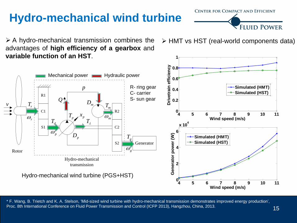
p
p
pT
dT
Rotor
px
QR1
C1
S1
R2
C2
S2
r
rTmT
m
g
gT
Hydro-mechanical
transmission
mD
pD
T
v
Generator
Hydro-mechanical wind turbine
Hydro-mechanical wind turbine (PGS+HST)
R- ring gear
C- carrier
S- sun gear
Hydraulic powerMechanical power
A hydro-mechanical transmission combines the
advantages of high efficiency of a gearbox and
variable function of an HST.
* F. Wang, B. Trietch and K. A. Stelson, ‘Mid-sized wind turbine with hydro-mechanical transmission demonstrates improved energy production’,
Proc. 8th International Conference on Fluid Power Transmission and Control (ICFP 2013), Hangzhou, China, 2013.
4 5 6 7 8 9 10 110
0.2
0.4
0.6
0.8
1
Wind speed (m/s)
Dri
vetr
ain
eff
icie
ncy
Simulated (HMT)
Simulated (HST)
4 5 6 7 8 9 10 110
2
4
6
x 104
Wind speed (m/s)
Gen
era
tor
po
wer
(W)
Simulated (HMT)
Simulated (HST)
HMT vs HST (real-world components data)
16
A. Power Regenerative Test Platform
M
VFD
Hydrostatic Transmission
(HST)Hydrostatic Drive
(HSD)
Virtual rotor Turbine output
Variable
Frequency
Drive
Virtual wind
simulated by
hydrostatic
drive
Real HST under test
To Investigate the performance of hydrostatic transmission
To test the advanced control algorithm
1. Capable of simulating a turbine output power of 105 kW
2. Small electric motor (55kW) to compensate for losses in the components (assuming overall
efficiencies of the pump and motor are 90% each)
55 kW
105 kW160 kW
17
Electric
power input
Virtual rotor
Turbine
output
180 cc Bosch
variable pump
135 cc Linde
variable motor
2512 cc Hagglunds
motors (act as pump)2512 cc
Hagglunds motors
A. Power Regenerative Test Platform
18
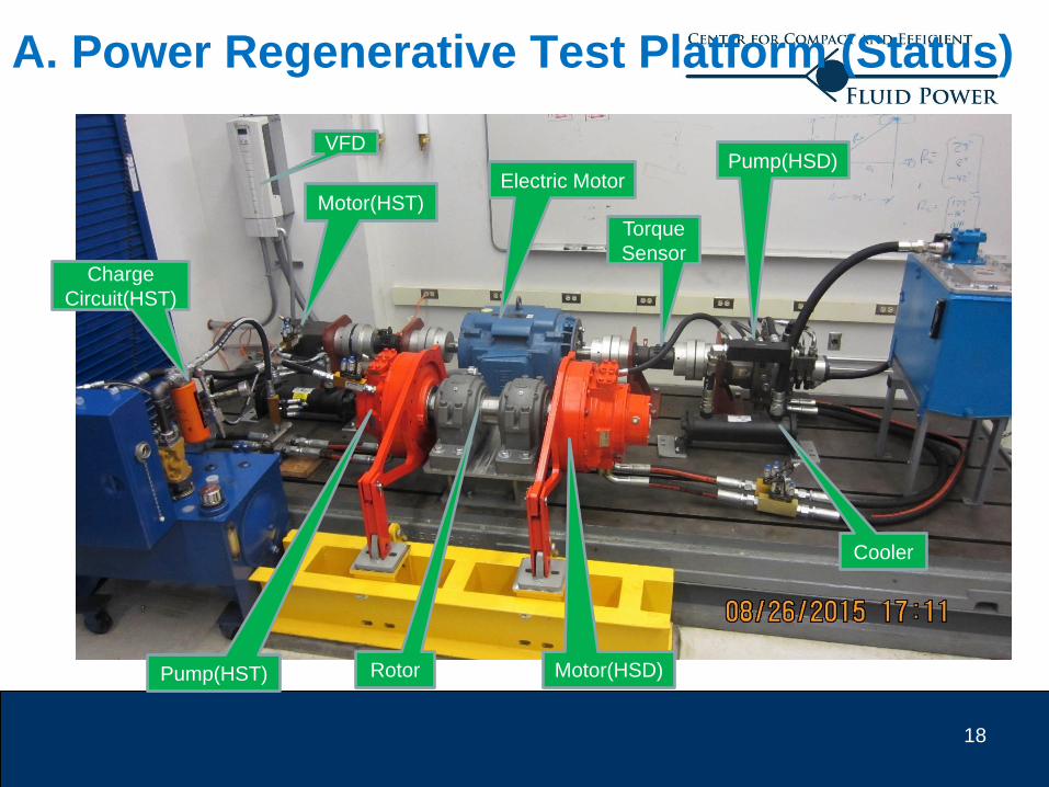
A. Power Regenerative Test Platform (Status)
VFD
Electric MotorPump(HSD)
Motor(HST)
Pump(HST) Rotor Motor(HSD)
Charge
Circuit(HST)
Cooler
Torque
Sensor
19
A. Wind turbine rotor simulation
Aerodynamic torque is a function of pitch angle,
rotor speed and wind speed
To simulate real dynamics of the rotor of a
turbine, the effect of the large blade inertia will
be virtually simulated and the modified torque is
applied on the rotor of the test platform
τ𝑑 = τ𝑟 − (𝐽𝑟 − 𝐽𝑠) ω𝑟
Design a controller to track desired torque
using HSD circuit
To generate aero dynamic torque for 105 kW
turbine by modifying the blade dynamics of the
FAST code
20
Conclusions
The proposed HST turbine control strategy based on torque control law is applicable to
the real world HST turbine.
Short-term energy storage with hydraulic accumulator can improve the turbine energy
production. A cost analysis is required to determine whether the energy increase will offset
the cost increase of implementing such system.
A hydro-mechanical transmission combines the advantages of high efficiency of a
gearbox and variable function of an HST, resulting a high turbine energy production. The
cost and reliability analysis is still required.
The power regeneration wind turbine test platform enables simulating the real word HST
turbine behaviors in the lab, providing a powerful tool to investigate research topics.
New improvements could come from advanced turbine control strategies, more efficient