Project - "Making the Grandfather's Clock - Veneering the Panels" ...continued Beth now spreads yellow glue over the top side of the MDF panel. She positions the burl veneer panel on the glued MDF piece. She lightly presses the veneer onto the panel.
Transcript
Project - "Making the Grandfather's Clock - Veneering the Panels" ...continued
Beth now spreads yellow glue over the top side of the MDF panel.
She positions the burl veneer panel on the glued MDF piece.
She lightly presses the veneer onto the panel.
Beth uses Saranwrap to cover the top and bottom. This keeps any glue that is squeezed out from attaching to the outer clamping boards.
She has placed the plastic wrapped sandwich on the trim board and is now placing the top in position. These boards will help spread the clamping pressure uniformly on the veneer sides. You have seen me use a vacuum bag for clamping veneer panels before. It would be great to use here, but we want to show that clamps can work well on small panels, such as this.
She has clamped the sandwich in the bench vise and is adding a couple of hand clamps to further squeeze the package. She will leave it to set overnight.
With the veneer work done for the moment, Beth turns to work on some of the solid walnut panels she had glued up last time.
She had never used a cabinet scraper before but quickly finds that it is easy to use and gives a super smooth finish to these small panels.
Here, Beth is laying the glass pieces in place on the front and side frames she had made last week. She will simply mark the outline of each piece of glass. If you recall, she opted not to change the rail and stile router bits to cut the rabbet. Instead, she will cut the rabbet now.
She holds the rabbeting bit next to the frame to visualize the cut.
Beth adjusts the router height until the bearing rides against the molding edge.
She has cut a small portion and now inspects to see if the rabbeting is deep enough. It should be as deep as the channel cut by the stile set.
She determines that the rabbet should be slightly deeper, so she changes the pattern bearing. The bearing set at the left allows her to adjust the rabbet depth by swapping bearings. This assortment of bearing is very handy for use with a lot of pattern bearing bits.
Project - "Making the Grandfather's Clock - Continuing the Frames
She now rabbets all the inside edges where the glass pieces will go.
The rabbet bit has given her a very nice and smooth rabbet, but, of course, the bearing's size has "rounded" the corners. Beth will have to try her hand with the chisel.
She starts by using a straight edge and knife to score a straight line using the straight part of the rabbet as a guide.
She uses the line to place her chisel and with a series of small cuts, makes a square corner.
With the bulk of the material removed, she uses hand pressure to shear the rabbet walls smooth.
Her first square corner looks fine. Now, 15 to go � but they do go very quickly.
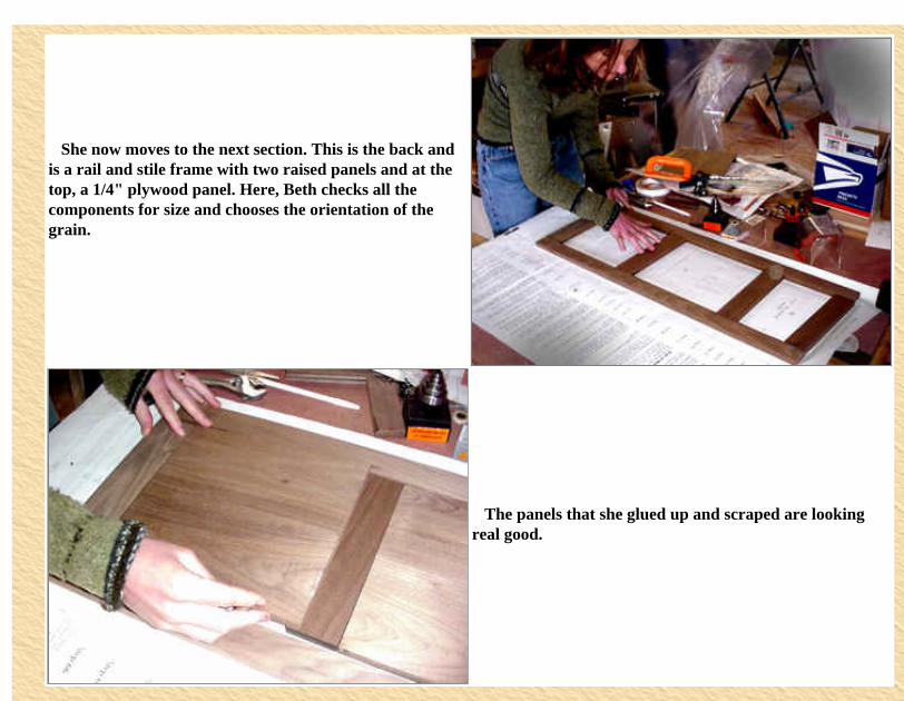
She now moves to the next section. This is the back and is a rail and stile frame with two raised panels and at the top, a 1/4" plywood panel. Here, Beth checks all the components for size and chooses the orientation of the grain.
The panels that she glued up and scraped are looking real good.
http://www.woodshopdemos.com/gclk-8.htm (3 of 3) [09/09/2008 9.52.30]
Project - "Making the Grandfather's Clock - Rail and Stile and Raised Panel Making
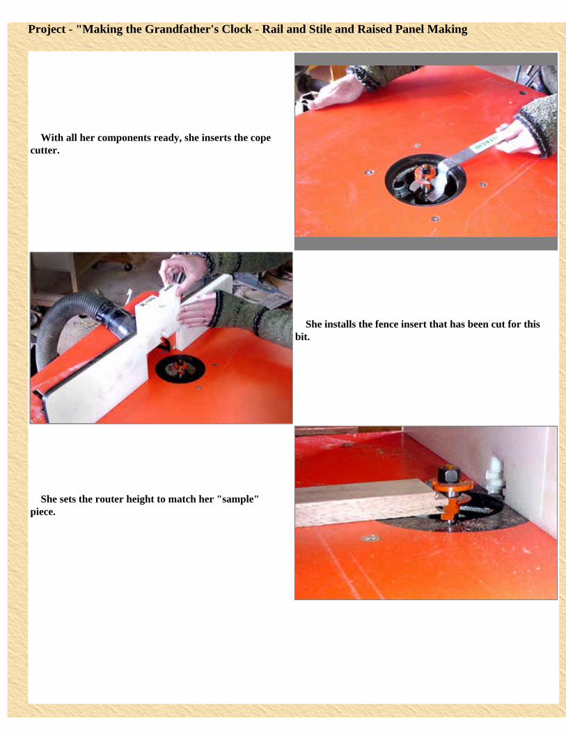
With all her components ready, she inserts the cope cutter.
She installs the fence insert that has been cut for this bit.
She sets the router height to match her "sample" piece.
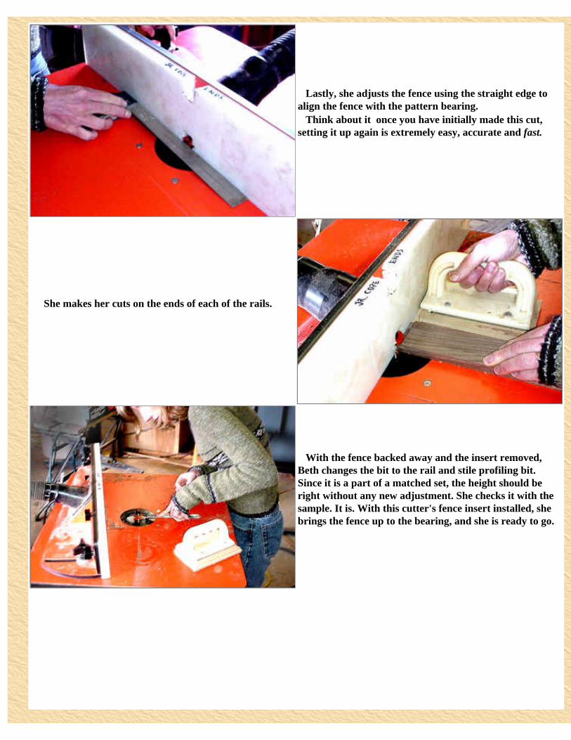
Lastly, she adjusts the fence using the straight edge to align the fence with the pattern bearing. Think about it � once you have initially made this cut, setting it up again is extremely easy, accurate and fast.
She makes her cuts on the ends of each of the rails.
With the fence backed away and the insert removed, Beth changes the bit to the rail and stile profiling bit. Since it is a part of a matched set, the height should be right without any new adjustment. She checks it with the sample. It is. With this cutter's fence insert installed, she brings the fence up to the bearing, and she is ready to go.
Having placed the sample on the infeed side, Beth has installed two feather boards. One in clamped to the fence and holds the piece down on the table. She is clamping the second to the table having positioned it to hold the piece tight against the fence.
She runs the stiles and the rails through the router giving each of the pieces their profile. All she has to do now is to shape the panels.
Beth uses the bent wrench to quickly change bits once again. This time, she places the "junior" raised panel cutter in the collet.
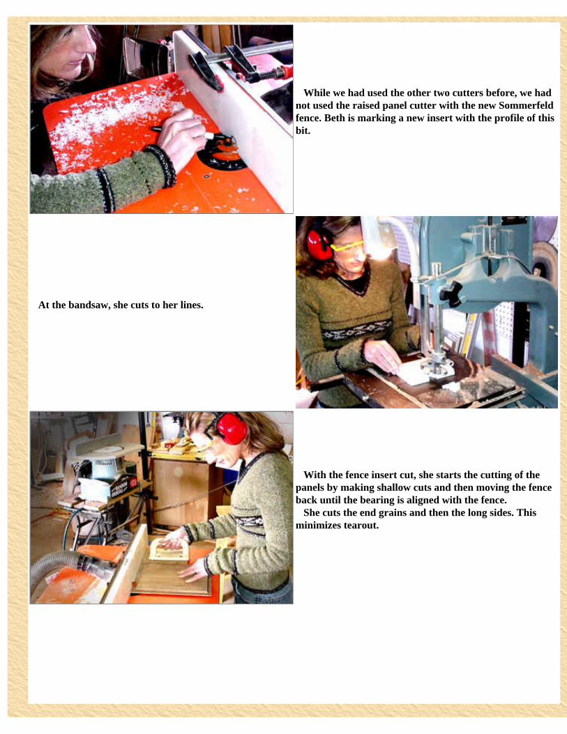
While we had used the other two cutters before, we had not used the raised panel cutter with the new Sommerfeld fence. Beth is marking a new insert with the profile of this bit.
At the bandsaw, she cuts to her lines.
With the fence insert cut, she starts the cutting of the panels by making shallow cuts and then moving the fence back until the bearing is aligned with the fence. She cuts the end grains and then the long sides. This minimizes tearout.
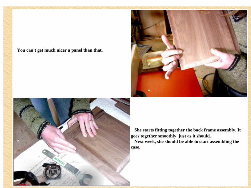
You can't get much nicer a panel than that.
She starts fitting together the back frame assembly. It goes together smoothly � just as it should. Next week, she should be able to start assembling the case.
Main Menu Previous Page Next Page
A "commercial" note: I have received many emails asking "where to buy" certain items mentioned in this story. They are all available from www.sommerfeldtools.com but may not be listed in the on-line catalog. That is why I am listing part numbers and prices here. Also, when ordering, please mention having seen it on "WoodShopDemos.com" Here is a list of all the products mentioned:
Description Part Number Price Other commentJr. Grandfather
Clock Plans Plan-001 $24.95 Sale: $19.95
Quartz Chiming Movement Movement-001 $39.95
Clock Templates ClockTemplates-001 $29.95
http://www.woodshopdemos.com/gclk-9.htm (5 of 6) [09/09/2008 9.54.02]
Project - "Making the Grandfather's Clock - Rail and Stile and Raised Panel Making
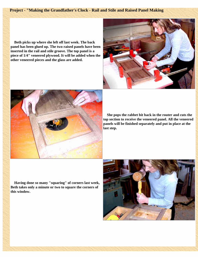
Beth picks up where she left off last week. The back panel has been glued up. The two raised panels have been inserted in the rail and stile groove. The top panel is a piece of 1/4" veneered plywood. It will be added when the other veneered pieces and the glass are added.
She pops the rabbet bit back in the router and cuts the top section to receive the veneered panel. All the veneered panels will be finished separately and put in place at the last step.
Having done so many "squaring" of corners last week, Beth takes only a minute or two to square the corners of this window.
The cabinet scraper quickly removes the little trace of glue squeeze out.
Beth takes a few minutes at the Delta Bench Random Orbital Sander to sand smooth both sides. This is where it helps to have the panels cut precisely. The panel surfaces are aligned with the rail and stile so that this flat sander can smooth both.
The instructions say to make sure that both assembled sides and front and back have the same widths. Beth puts them next to each other and decides that her units are exactly matched.
The plans call for a tongue and groove set to be used to join the four sides. I would not have thought of this for joining the assembly. I think I would have tried using the locking miter bit � that would have given a joint without a seam showing. Beth and I searched through the plans and found that the "seam" will be covered by a strip of molding. So this joint makes sense. It is similar to dadoing the pieces on the table saw, except that the tongue automatically matches the groove width producing a tight joint.
Two grooves will be cut into the length of both sides. The tongue is designed to cut a 1/4" width. The bearing allows a 3/8" depth of cut � much too much for 1/2" stock. The plans explain how to swap the pattern bearing to make a 1/4" cut. Rather than to change bearings, Beth and I decide that we can use the fence to limit this depth.
She installs the groove cutter.
Beth adjusts the fence so that the cutter depth is 1/4". She has raised the router so that the cutter is 1/8" above the table. Note, the "sawdust." This is actually white plastic from the fence insert. Beth found that the zero clearance insert cut for the Junior Raised Panel was close enough and could be used for this operation with just a small additional routing.
Beth has clamped a featherboard in place to keep pressure on the side as it is routed.
With the grooves cut in the sides, Beth now installs the other cutter. This one will be adjusted so that it cuts a tongue that is centered on the 1/2" frame stock.
After having checked all the inserts, Beth decides that a new one will have to be cut just for this cutter. She marks the profile outline.
Beth cuts the shape at the bandsaw.
http://www.woodshopdemos.com/gclk-10.htm (5 of 5) [09/09/2008 9.55.41]
Project - "Making the Grandfather's Clock - Putting the Case Together
Beth adjusts the fence to give her the 1/4" tongue depth. Of course, she will run a sample before running the actual frames.
Having made the sample cut and positioning a couple of featherboards to keep the panel flat on the table, Beth makes the tongue cut on the edge of both the front and back panels.
The next step, is to cut a dado across all the panels to hold a floor in place. We were concerned that the dado would show through at the corners, but a search of the plans showed us that it would be covered by the base unit. Beth has installed the tongue cutter back in the router and has raised it to make the cut.
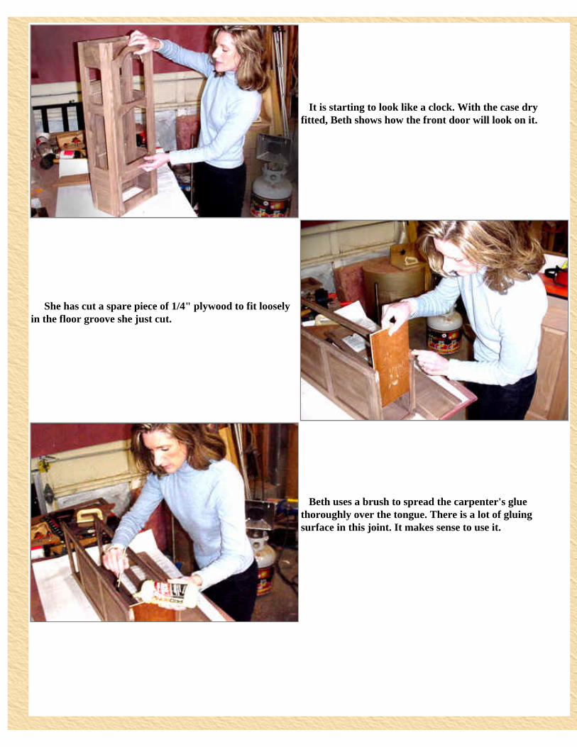
It is starting to look like a clock. With the case dry fitted, Beth shows how the front door will look on it.
She has cut a spare piece of 1/4" plywood to fit loosely in the floor groove she just cut.
Beth uses a brush to spread the carpenter's glue thoroughly over the tongue. There is a lot of gluing surface in this joint. It makes sense to use it.
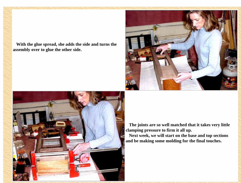
With the glue spread, she adds the side and turns the assembly over to glue the other side.
The joints are so well matched that it takes very little clamping pressure to firm it all up. Next week, we will start on the base and top sections and be making some molding for the final touches.
Main Menu Previous Page Next Page
http://www.woodshopdemos.com/gclk-11.htm (3 of 3) [09/09/2008 9.57.01]
Project - "Making the Grandfather's Clock - Making the Top Frame"
Two weeks ago, Beth had bookmatched and glued up some figured walnut burl. In the interim, we have been French polishing to see how high a gloss we could get. It is looking good. We will probably do all the veneered panels this way.
Each of the veneer panels will be shaped and the edges raised. That will come later, right now it is time to continue with the frames.
Beth starts the top frame section. She notes that the drawings call for 1 1/2" square stock or to glue up three pieces of 1/2" stock. The 1 1/2" square stock is then rabbeted to give the 1/2" sides. We looked at this for some time and decided that it we were very careful, we could use 1/2" pieces and use the locking miter joint to give us the nice crisp corner.
Beth has seen the locking miter bit used but has not used it herself. I said that the joint is great and easy to do if you follow the basic set-up rules.
She is using the bent wrench to install the bit in the router. She has already put the fence insert in place for this bit. I have cut an insert for this bit. One side on the insert is with the bit centered on 1/2" stock, and the other side is for it centered on 3/4" stock. The custom insert will give Beth a smoother cut and is better for dust collection.
She sets the height of the bit to be approximately at the 1/2 point of the stock. With this, she runs two pieces of stock. One is marked "A" and the other "B". She runs the "A" side up and the "B" side down.
She places the two cut pieces together. She was lucky. The two lined up perfectly. She is ready to make the cuts.
On each of the corners, she selects one piece to be run flat on the table.
She runs the mating piece against the fence. The walnut mills very well. While the fence was set to make the final cut in one pass, she makes a second pass just to "clean out" the cut.
Beth inspects her corner pieces. They fit together perfectly and give a sharp, square outside corner. What's best is that the sides are already the 1/2" stock, so they can now be routed with the rail and stile cutters to fit the rest of the frame section.
Project - "Making the Grandfather's Clock - Making the Top Frame"
With the corner posts done, Beth figures out which will be the stile for the side panel.
It is time to cut the cope ends on all the rails of the sides and the front panel. She selects the cope cutter � it is the one with the bearing in the middle.
She installs the bit.
Beth sets the router bit height by the sample she had cut last week.
She slides the insert that is cut for that profile. Each fence insert is labeled with the profile.
She brings the fence forward until it is aligned with the pattern bearing and locks it in place.
She makes the cut on the ends of each of the rails. Her right hand is holding the push pad that is attached to a piece of 1/2" MDF. This serves as a push stick and as a backer board. The push pad in her left hand is used to keep the piece flat on the table and against the fence.
Now, Beth has switch cutters and fence inserts and makes her cut along the lengths of all the pieces.
It has taken Beth very little time to make the cuts using the CMT/Sommerfeld Junior Raised Panel Set. The two profile bits are matched so that once you have one set to the correct height, the other bit can be used without resetting the router height. This feature is also a feature of the standard raised panel set and really makes using these cutters easy.
With the ends of the rails coped, Beth attaches one of the templates to a rail piece which will be shaped with the graceful crown at the top of the clock.
Beth takes the piece to the bandsaw and very carefully cuts the wood staying about 1/8" away from the template.
She has installed a trim bit so that the bearing is in contact with the template and the cutter covers the wood. The inset shows a closer, "birdseye" view.
Beth makes her cut. When she is coming up against the cross grain, she is careful to take minimal cuts and little pressure � letting the cutter do its work. A very sharp cutter and not pushing it greatly reduces the chip out problem.
She examines the cut and finds that it is smooth and exactly matches the template.
Beth examines her progress. She has done one more template curving now and has quite a number to go. Some of the curve cutting gets more difficult to handle � smaller pieces and less wood to hold on to. For that reason, we decided to stop right here. Next week I will try to put together a small jig to make the shape cutting easier and safer. We have a lot left to do but will try to wrap it up next week so we can start on some new projects.
I don't know if I have shown you this exploded parts view of the clock. I present it now to show that the project is complex but simple. The simple part is that the various "frames" (sides, front, back, door, etc.) are all really much the same series of tasks. You cut the pieces, then cut the cope ends, then the sides, then the panels, and a frame is done. For those of you whom I have now confused, let me go through one such "frame". I think it is important to understand this because so many people have looked at the clock in progress and have said "wow, that is too complex." It isn't once you understand the making of one frame.
I have had requests from several readers to do in greater detail the making of the raised panel and rails and stiles. So, I will try to do it in a step-by-step fashion. This is where Beth and I left off last week. She had just cut some of the elements for the top crown section.
I am starting by laying out the next section. If you go to the exploded section drawing above, this will be the bottom (blue) section � without the molding elements that are pictured. We will add that later. Note, that as Beth did last week, we have corner sections that I will make from two 1/2" pieces using the locking miter bit. I will do that first.
I have installed the locking miter bit. I have also brought out my sample that I cut from the same stock. I will use that to setup the router bit height and fence depth.
Having a sample block does make the set up of any bit very fast and accurate. From this view, you can see that the bit height is not left to guess work or trail and error. It can be very exact.
I store the sample cut with the fence insert for that bit. This insert happens to have two profiles cut in it. One is for this bit in 1/2" stock and the other for 3/4" stock. Labeling helps to keep the inserts straight.
As I do every time that I put an insert in the fence, I first check to see that it clears the stopped cutter. Then, while standing behind the fence, I turn on the router and move the fence cautiously over the router. That serves to cut any minor discrepancies of the bit setup and is a good safety procedure.
When the router comes to a complete stop, I move the fence into the bit and use the sample cut to adjust the fence depth.
I will make one cut on each corner piece with the stock flat on the table. In my right hand I am holding the push block with the 1/2" MDF. This has the locking miter shape and is used as a backer board. I will push the stock through the bit with this hand. My left hand has the standard push block. I use this to hold the stock flat on the table and against the fence. Remember, my right hand is doing the feeding of the stock through the cutter.
This is the cut. The arrow points to the outside edge which should be knife sharp. If there is any width to it, the fence needs to be backed off slightly. On the other hand, when you are running the stock and you see a slight gap on the outfeed side of the fence, the fence should be adjusted in until it touches the stock. These very slight adjustments can mean the difference between a "nice" fit and an exact, seamless fit.
I will run the mating two pieces vertically against the fence. My right hand will hold the push pad that I have rotated so that another section of MDF is used. My left hand will use the standard push pad to keep the work against the fence and riding on the table.
This is my CMT/Sommerfeld Junior Raised Panel bit set. I have been using it more than a year now, and it is great to use. The two rail and stile profile cutters are matched which makes setting up for tight joints very easy.
This is what I am working on. The "L" on the right is made up of the two stiles I just profiled with the locking miter bit. I will cut the cope ends on the two crosspieces, the rails, first.
The cope cutter is the one with the bearing in the middle.
Using the bent wrench, I install the cope bit in the router. My right hand is holding the knob that is connected to the shaft lock of the Hitachi M12V router.
I have said many times, that I love the bent wrench. I realize that what I haven't mentioned is that the Hitachi M12V collet is amazing. It takes less than a 1/4-turn to lock and unlock the collet. Every other router I own takes one or more turns. This setup I have makes changing bits amazingly quick and easy.
I have installed a throat plate and am now setting the router bit height using the coped end of my sample.
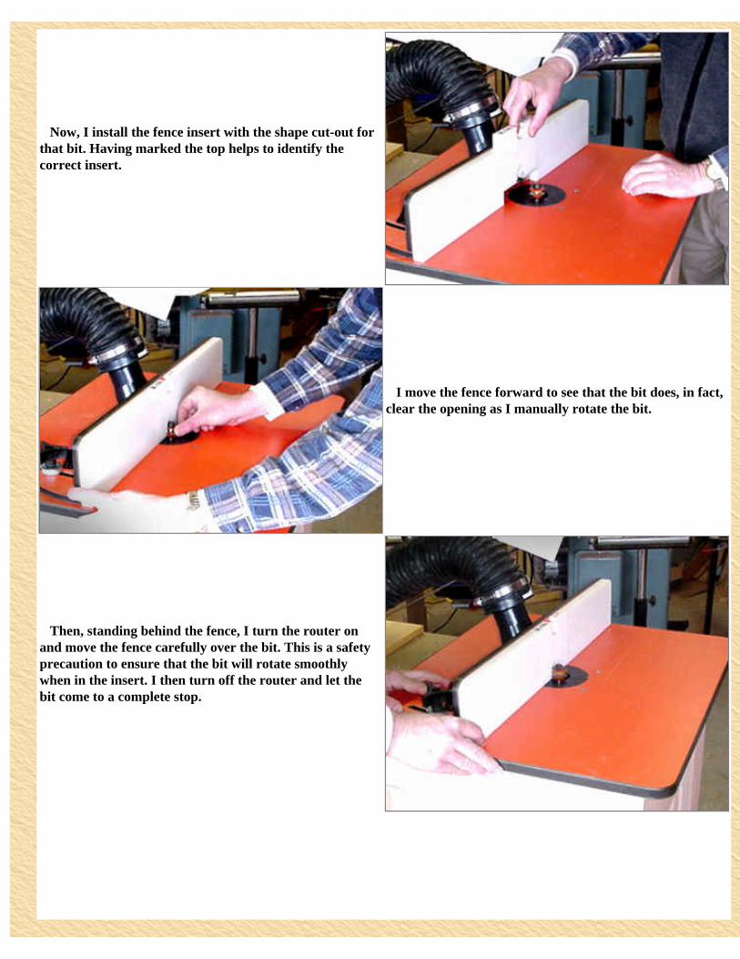
Now, I install the fence insert with the shape cut-out for that bit. Having marked the top helps to identify the correct insert.
I move the fence forward to see that the bit does, in fact, clear the opening as I manually rotate the bit.
Then, standing behind the fence, I turn the router on and move the fence carefully over the bit. This is a safety precaution to ensure that the bit will rotate smoothly when in the insert. I then turn off the router and let the bit come to a complete stop.
I now use a straight edge to align the fence with the pattern bearing. I lock the fence in place and, one more time, rotate the bit to be sure that it is free to move. With that done, I am ready to cut the cope ends on the rails. All cuts are made with the face (outside) down and flat on the table. If in doubt, mark all the pieces with an "X" on the inside face � this "X" then will be facing up when making the cut.
The fence is used to guide the ends of the rails. I have added a new piece of MDF to the push block. This will serve as a backer board and will keep the rail perpendicular to the fence.
A second push block allows me to use my left hand to hold the rail against the MDF-pushblock and the fence and flat on the table. The right hand does the pushing of the rail through the cutter. The customized, zero-clearance, insert keeps the stock from "dipping" into the space around the bit. Even with these narrow pieces, this system works well � cutting clean, coped ends.
I test fit this newly cut rail to my sample piece. It fits perfectly, so I can make all the cuts on both ends of each of the rail pieces.
http://www.woodshopdemos.com/gclk-14a.htm (5 of 5) [09/09/2008 10.04.47]
With the rail ends coped, we can change bits and cut the profile on the rails and stiles that will accommodate the raised panel. The bit I install now is the bit with the bearing at the top. Note, that I press the bit down to "bottom it out." In fact, it is bottomed on the 1/2" diameter O-ring I have placed at the bottom of the collet. This keeps the bit shaft from getting locked in place when tightening the collet. With the bit installed like this, it should match exactly the height that we used for the cope bit.
I tighten the bit using the bent wrench.
I use the sample piece to double-check the height. When the router bit is rotated, the cutter should just "kiss" the groove of the sample. It does.
The correct fence insert is installed. Since I have cut this insert in the other edge of the same insert, all I have to do is switch it end for end.
Just as before, I move the fence forward to see if this insert clears the installed bit. Then, standing behind the fence, I turn the router on and move the fence over the router bit. If you look real closely, you will see a few flakes of freshly cut white plastic. Once I have made this cut, I can turn off the router and set the fence depth.
With the router turned off and the bit at a complete stop, I align the fence with the top bearing and lock it in place. I am ready to run the stock.
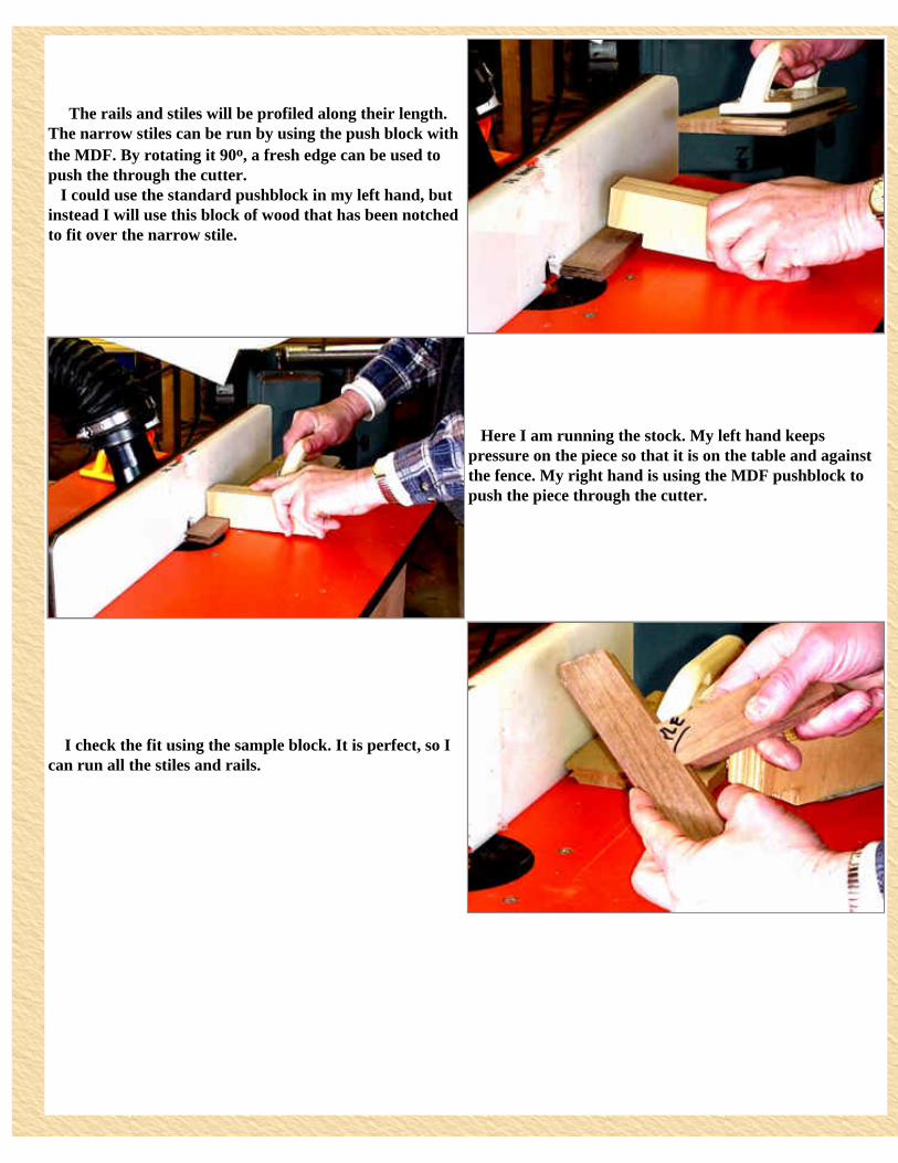
The rails and stiles will be profiled along their length. The narrow stiles can be run by using the push block with the MDF. By rotating it 90o, a fresh edge can be used to push the through the cutter. I could use the standard pushblock in my left hand, but instead I will use this block of wood that has been notched to fit over the narrow stile.
Here I am running the stock. My left hand keeps pressure on the piece so that it is on the table and against the fence. My right hand is using the MDF pushblock to push the piece through the cutter.
I check the fit using the sample block. It is perfect, so I can run all the stiles and rails.
For the wider rails, I switch back to the standard pushblock.
With all the pieces profiled, I can start to assemble the three sides.
I am only dry fitting at this point and want to give you an idea of how the sections go together. The locking miter joint, we did first, will be the corner post. [Note, the gap at the corner is because I am not holding the corner together.] Now, let's take a look how we made the template panel cuts.
With the rail and stiles cut for our frame, we can cut the raised panel to fit inside a frame. [Note: this is actually a raised panel for another frame.] Some panels will be square and some will be curved to fit the curved rail sections. We will use this panel as an example.
I, first, will attach the appropriate template to the dimensioned board. The instructions say to use two nails for this. I am using 5/8" sheet metal screws. I have pre-drilled the template to locate the screws well enough in so that the screw hole will not protrude in the raised panel cutter area. I am working from the back. The face is flat down on the table.
At the bandsaw, I carefully cut the shape, staying about 1/8" away from the template.
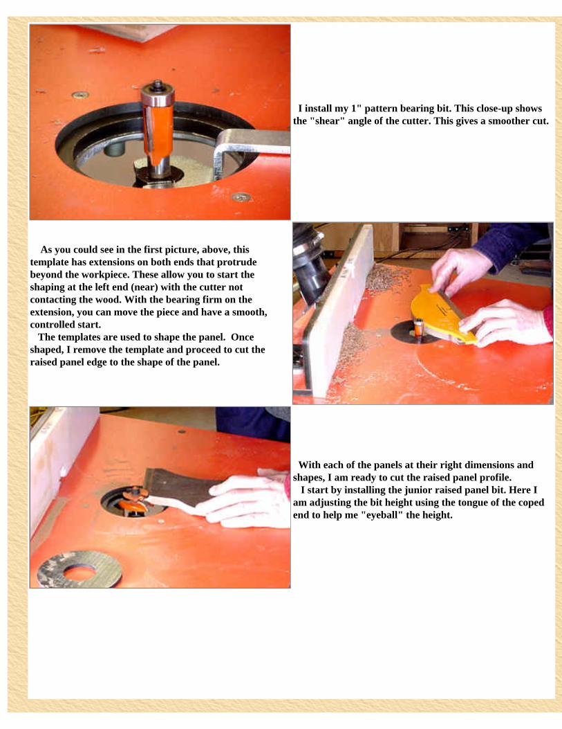
I install my 1" pattern bearing bit. This close-up shows the "shear" angle of the cutter. This gives a smoother cut.
As you could see in the first picture, above, this template has extensions on both ends that protrude beyond the workpiece. These allow you to start the shaping at the left end (near) with the cutter not contacting the wood. With the bearing firm on the extension, you can move the piece and have a smooth, controlled start. The templates are used to shape the panel. Once shaped, I remove the template and proceed to cut the raised panel edge to the shape of the panel.
With each of the panels at their right dimensions and shapes, I am ready to cut the raised panel profile. I start by installing the junior raised panel bit. Here I am adjusting the bit height using the tongue of the coped end to help me "eyeball" the height.
I have lowered the router speed. This is a 2 1/2" bit and the maximum speed for that diameter is 16,000. Just as I did with the other bits, I have installed the insert for this bit and have run the router through the cutout. I am now aligning the fence with the bearing in the middle of the cutter. All the veneered panels that need this shape are shown on the table � patiently awaiting their edging.
Using the two push block method that I have used in the earlier procedures, I cut the raised panel profile on each of the square panels. I also cut the shape on the ends of the curved panels. I will show you why, in a second. With the regular size raised panel bit, you need to make this cut it several stages. The junior raised panel bit is smaller, and the cut can be made in one pass. I make the first pass a "light" pass and then make a second finishing pass.
I said a minute ago that you want to shape the ends of the curved panel. Here is why. In the picture at the right, I have moved the workpiece against the cutters bearing. Since this short edge was routed in the last step, I can safely ease the workpiece onto the bearing at this pre-shaped location. Once on the bearing, I can ease the piece "around the corner". The bearing will always be firmly on the piece so all I have to do is to control the feed rate. The blue tape keeps the insert plate from being lifted by air coming from the router's fan.
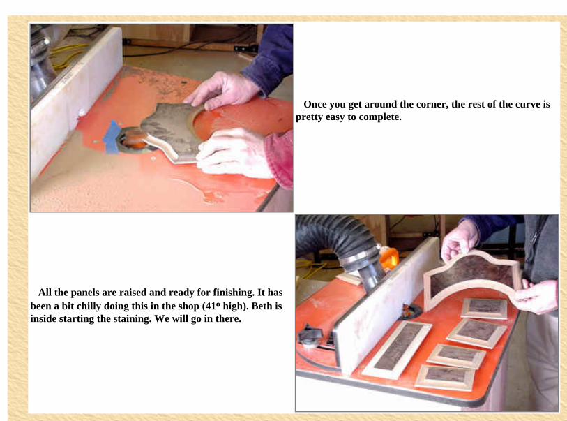
Once you get around the corner, the rest of the curve is pretty easy to complete.
All the panels are raised and ready for finishing. It has been a bit chilly doing this in the shop (41o high). Beth is inside starting the staining. We will go in there.
http://www.woodshopdemos.com/gclk-16.htm (4 of 4) [09/09/2008 10.07.44]
Well, Beth liked the idea that the panels needed to be finished inside where it is nice and toastie. The 41o shop (on a warm day) is getting to both of us.
As you know, we used MDF for the veneered panels. Now, Beth is attempting to "hide" the MDF edges. We found a "Brown Leather" color in the pre-mixed acrylic enamels. Beth is brushing the first coat on the exposed MDF edges
This is a panel that was given the first coat yesterday. She uses a piece of rolled up 220 grit sandpaper to smooth the painted area. The first coat raised the MDF slightly. This smoothes it out just fine.
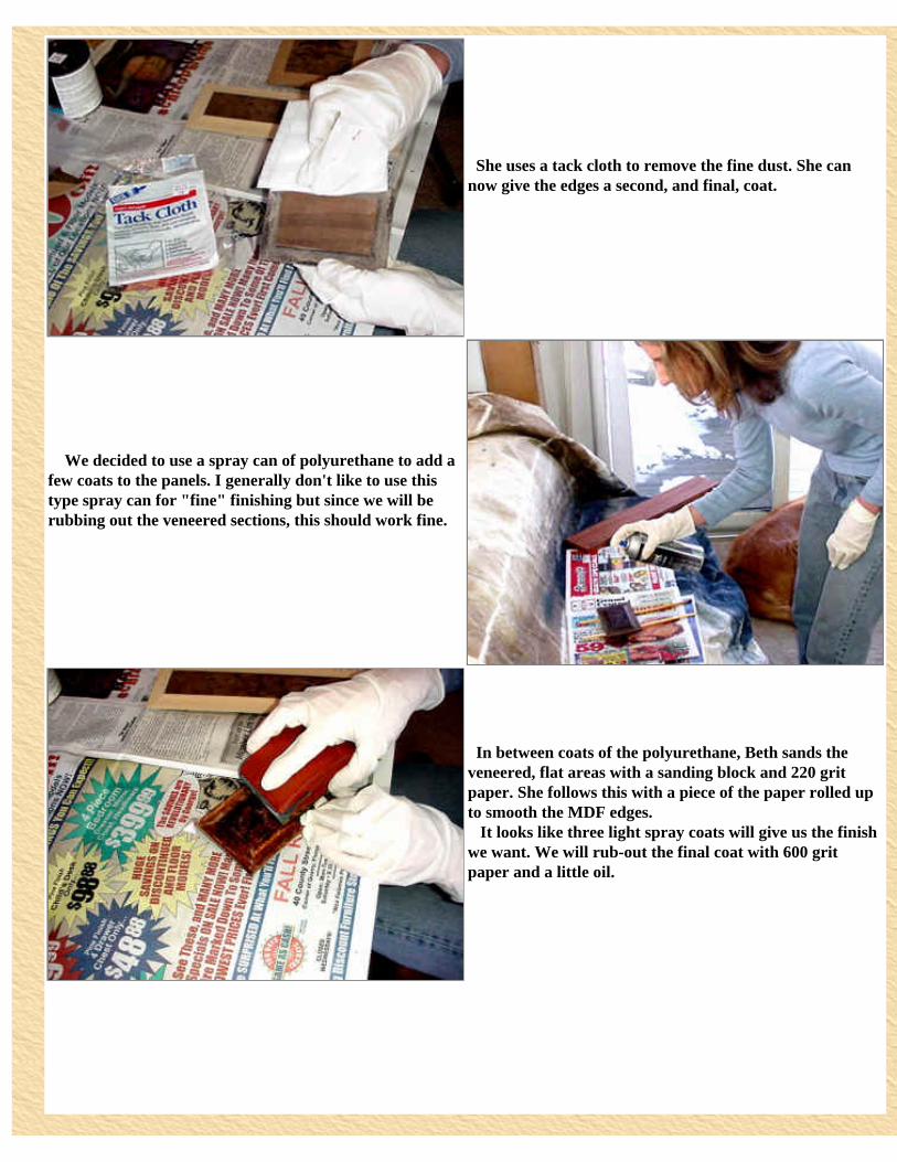
She uses a tack cloth to remove the fine dust. She can now give the edges a second, and final, coat.
We decided to use a spray can of polyurethane to add a few coats to the panels. I generally don't like to use this type spray can for "fine" finishing but since we will be rubbing out the veneered sections, this should work fine.
In between coats of the polyurethane, Beth sands the veneered, flat areas with a sanding block and 220 grit paper. She follows this with a piece of the paper rolled up to smooth the MDF edges. It looks like three light spray coats will give us the finish we want. We will rub-out the final coat with 600 grit paper and a little oil.
The clock case isn't ready for finishing, but Beth uses this opportunity to apply some oil finish to a spare piece of the walnut.
On another spare piece of walnut, Beth applies the wipe-on polyurethane that we had used on the small clocks we made for Christmas presents. We will give both samples 3 coats and see which we like better for the whole assembly. Next week, we may be working on the final assembly and finishing this project.
http://www.woodshopdemos.com/gclk-17.htm (3 of 3) [09/09/2008 10.09.01]
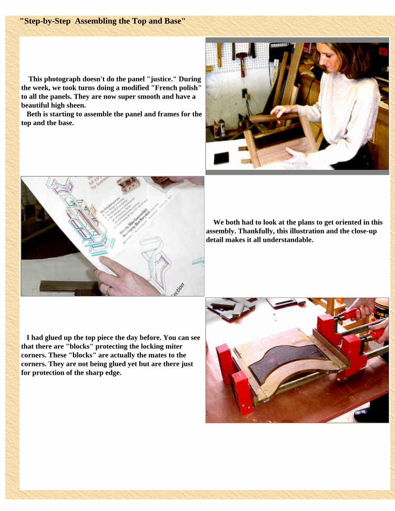
This photograph doesn't do the panel "justice." During the week, we took turns doing a modified "French polish" to all the panels. They are now super smooth and have a beautiful high sheen. Beth is starting to assemble the panel and frames for the top and the base.
We both had to look at the plans to get oriented in this assembly. Thankfully, this illustration and the close-up detail makes it all understandable.
I had glued up the top piece the day before. You can see that there are "blocks" protecting the locking miter corners. These "blocks" are actually the mates to the corners. They are not being glued yet but are there just for protection of the sharp edge.
Beth tries this panel in place on the cabinet to get an idea of how it will look. The top curve was purposely left straight. It can be shaped now. Having the rest of the frame to hold on to will help this task.
Working from the back, she attaches the template for the upper curve. As before, she uses two 5/8" sheet metal screws to temporarily secure it to the frame.
At the bandsaw, she carefully cuts the shape, leaving about 1/8" to trim off in the next step.
Beth shapes the edge using the trim bit's bearing guided by the template.
She admires the clean, smooth cut that the template and trim bit gives the piece.
At this point, Beth turns her attention to the bottom section. She wants to check that the front and sides will have clearance to wrap around the base. It fits perfectly.
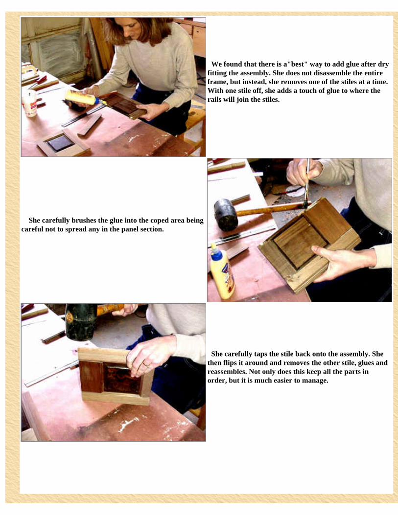
We found that there is a"best" way to add glue after dry fitting the assembly. She does not disassemble the entire frame, but instead, she removes one of the stiles at a time. With one stile off, she adds a touch of glue to where the rails will join the stiles.
She carefully brushes the glue into the coped area being careful not to spread any in the panel section.
She carefully taps the stile back onto the assembly. She then flips it around and removes the other stile, glues and reassembles. Not only does this keep all the parts in order, but it is much easier to manage.
She places the side panel in the clamps to dry. Note that she has a front panel clamped as well. This is not glued at this point. It is in the clamp to mate with the locking miter corner to keep the corner from being crushed by the clamp.
Main Menu Previous Page Next Page
http://www.woodshopdemos.com/gclk-18.htm (5 of 5) [09/09/2008 10.10.08]
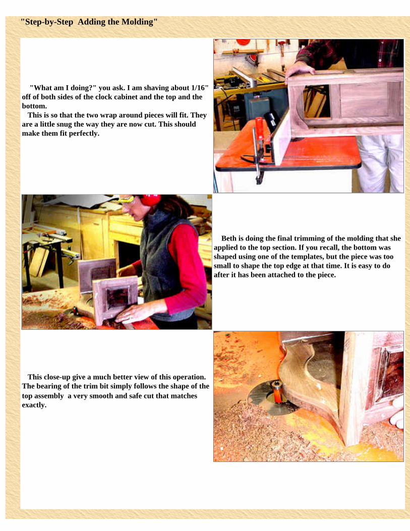
"What am I doing?" you ask. I am shaving about 1/16" off of both sides of the clock cabinet and the top and the bottom. This is so that the two wrap around pieces will fit. They are a little snug the way they are now cut. This should make them fit perfectly.
Beth is doing the final trimming of the molding that she applied to the top section. If you recall, the bottom was shaped using one of the templates, but the piece was too small to shape the top edge at that time. It is easy to do after it has been attached to the piece.
This close-up give a much better view of this operation. The bearing of the trim bit simply follows the shape of the top assembly � a very smooth and safe cut that matches exactly.
Now she can slide the top assembly over the top of the case. The door is not mounted yet but is in place to help Beth locate the top exactly.
Beth and I have been sanding each piece at every step of the way. She uses the orbital sander and 220 grit paper to remove a few glue marks. She is using the orange pad to keep the sander away from the finished raised panel � it would not be good to scratch these veneered surfaces that we have labored over.
Beth has ripped several pieces of walnut to the dimensions specified for the molding pieces. The piece that she is now measuring she thinks may be wider than what we think would look good. We decide to shape the edge and then try it in place. We can always rip it narrower at that point.
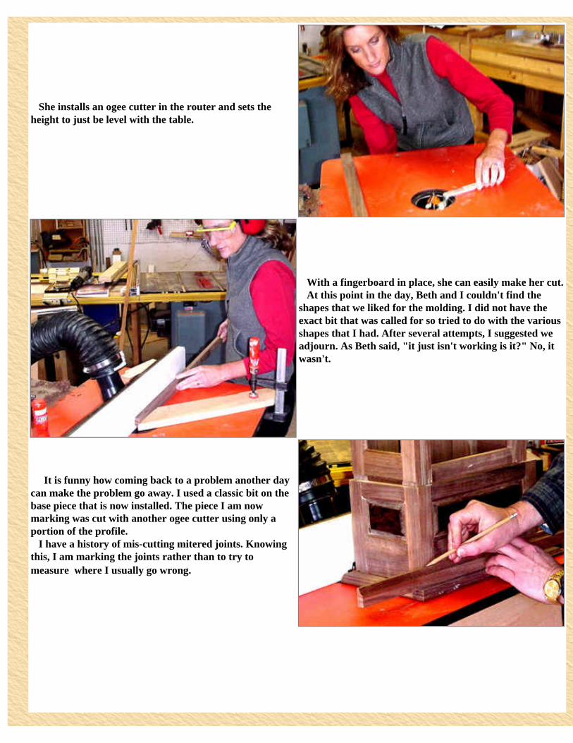
She installs an ogee cutter in the router and sets the height to just be level with the table.
With a fingerboard in place, she can easily make her cut. At this point in the day, Beth and I couldn't find the shapes that we liked for the molding. I did not have the exact bit that was called for so tried to do with the various shapes that I had. After several attempts, I suggested we adjourn. As Beth said, "it just isn't working is it?" No, it wasn't.
It is funny how coming back to a problem another day can make the problem go away. I used a classic bit on the base piece that is now installed. The piece I am now marking was cut with another ogee cutter using only a portion of the profile. I have a history of mis-cutting mitered joints. Knowing this, I am marking the joints rather than to try to measure � where I usually go wrong.
When we started this project, I reported that I installed a brand new CMT compound miter saw blade. It has performed flawlessly in all the cross cuts so far. Now, it is making picture frame perfect corner cuts. [By the way, I have retracted the guard only for the picture. It releases as soon as I start the cut. Table saw guards should be so well engineered.]]
I glue the pieces in place and add a brad at each corner.
The two pieces of base molding are installed and look just fine. Now to attack the molding for just above the bottom raised panel frame. This is the one we were having trouble with yesterday.
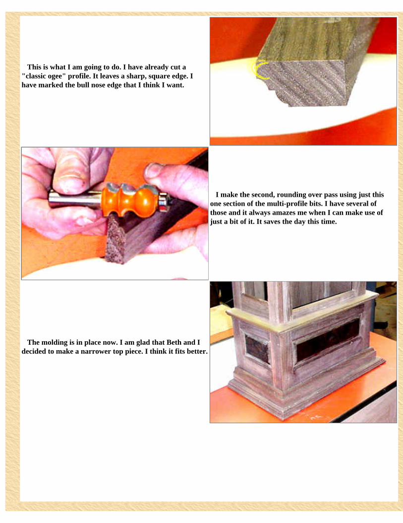
This is what I am going to do. I have already cut a "classic ogee" profile. It leaves a sharp, square edge. I have marked the bull nose edge that I think I want.
I make the second, rounding over pass using just this one section of the multi-profile bits. I have several of those and it always amazes me when I can make use of just a bit of it. It saves the day this time.
The molding is in place now. I am glad that Beth and I decided to make a narrower top piece. I think it fits better.
I am holding the door in place. I have to find overlap hinges that will look right in this piece. Next, I have to mount the stage for the clock itself. Then we can move to the warmth (yea!) of the house for the finishing steps.
http://www.woodshopdemos.com/gclk-19.htm (6 of 6) [09/09/2008 10.11.18]
Last week, Beth and I added the molding around the base and top units. What I forgot is that there is also a piece of molding that covers the butt joints of the sides and front. I start by cutting a 7/8"square of walnut. I must say, that I really appreciate the Grip-Tite magnetic hold downs for ripping narrow pieces.
At the router, I make several passes with the rabbeting bit. This piece will be an outside corner molding so I want to rabbet the inside to leave 1/4" sides. The two finger boards help to keep the stock square against the fence.
Several router passes later and you can see what the outside molding looks like. The two edges have a slight ogee shape, and I am now rounding over the outside corner. The trick to making moldings is to set up each cut with sufficient hold downs or to use push blocks. The smoother the routing, the less follow-up sanding is required.
I use the Delta Bench Random Orbital Sander with 220 grit to give a fine smoothing to the outside edges.
A couple of brads hold the molding in place while the glue sets.
This is a good time to sand of few of the edges that haven't yet been touched. I am "feathering" the edges of the door recess.
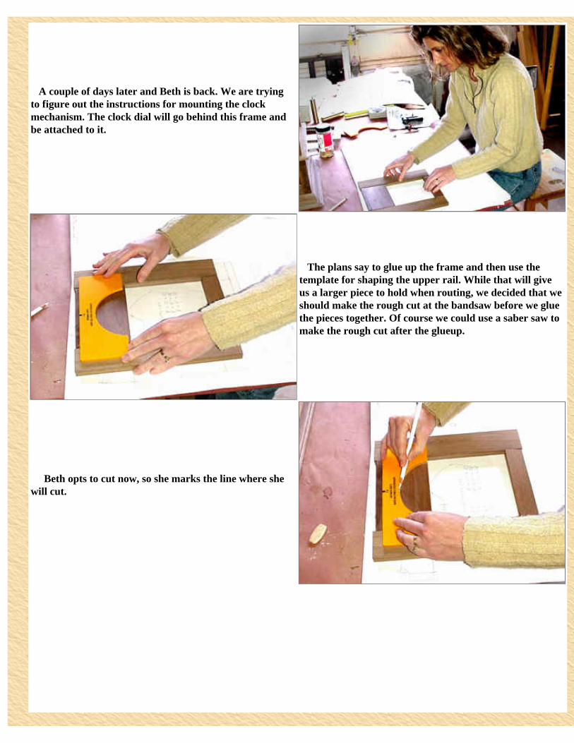
A couple of days later and Beth is back. We are trying to figure out the instructions for mounting the clock mechanism. The clock dial will go behind this frame and be attached to it.
The plans say to glue up the frame and then use the template for shaping the upper rail. While that will give us a larger piece to hold when routing, we decided that we should make the rough cut at the bandsaw before we glue the pieces together. Of course we could use a saber saw to make the rough cut after the glueup.
Beth opts to cut now, so she marks the line where she will cut.
Note that she started by cutting a relief cut to the center of the radius. This will allow her to remove the first portion at the mid-point. It is a tight curve, but since this is a rough cut, she takes her time and makes the cut staying away from her line.
She attaches the template for routing the upper rail. Beth is working from the back of the frame. Two 5/8" sheet metal screws hold the template in position. With the template mounted, we tried the piece on the router, and re-affirmed that we should wait until the assembly is glued up. The instructions are right here.
The bottom rail is too narrow for any of the biscuits we have, so Beth has cut down a #20 biscuit. The bottom of the rail will be out of sight, so she makes her mark favoring that side.
With the 5/32" slot cutter mounted in the router, Beth eases the pieces into the cutter at the marks.
Beth has become expert at gluing and clamping these frame assemblies together.
We have to wait for this frame to set before we can go much further.
Before quitting for the day, Beth reads forward and sees that a 3/8" hole has to be drilled in the brass dial. She leaves it in its protective plastic to keep it clean and scratch free.
It is looking more like a clock, but as Beth tries the dial in place, she realizes that it will be centered on the piece that is now drying and that is centered on the door opening � so, we are forced to stop here. Next week, we will be able to finish the assembly and start the finishing. This will be perfect timing because we have a bunch of spring projects we want to start.