IEEE 802.3az January 2008 Interim Meeting Proposal of Low-Power Idle 100Base-TX January 2008 IEEE 802.3az Task Force Presenter: Joseph Chou Realtek Semiconductor Corp. Contributors: Albert Kuo, Dachin Tseng, Jian-ru Lin, Ken Huang
Transcript
IEEE 802.3az January 2008 Interim Meeting
Proposal of Low-Power Idle 100Base-TX
January 2008IEEE 802.3az Task Force
Presenter: Joseph ChouRealtek Semiconductor Corp.
Contributors: Albert Kuo, Dachin Tseng,Jian-ru Lin, Ken Huang
IEEE 802.3az January 2008 Interim Meeting
2 Supporters
• Robert Hays (Intel)• Brad Booth (AMCC)• Adam Healey (LSI)• Brian Murray (LSI)• Dan Dove (HP)
– Transition to Idle State– Transition to Wakeup State– Refresh Signal
• Transition Timing Diagram• Simulation Result of Feasibility • Implementation Considerations• Single Ethernet PHY Block Diagram• Estimation of Power Consumptions• LPI Transition State Diagrams• Further Discussions • 802.3 100Base-TX Standard Modifications
– Auto-negotiation Capability pages & State diagrams– Additional 4B/5B (for 100Base-TX) Codeword used– PCS State diagrams
IEEE 802.3az January 2008 Interim Meeting
4
Realtek Single Port Ethernet NIC RTL816XPower Measurement (PCIe+MAC+PHY)
0
100
200
300
400
500
600
700
800
900
No link 10 100 1000
Baud rate (Mbps)
Ave
rage
Pow
er (
mW
)
ActiveIdle
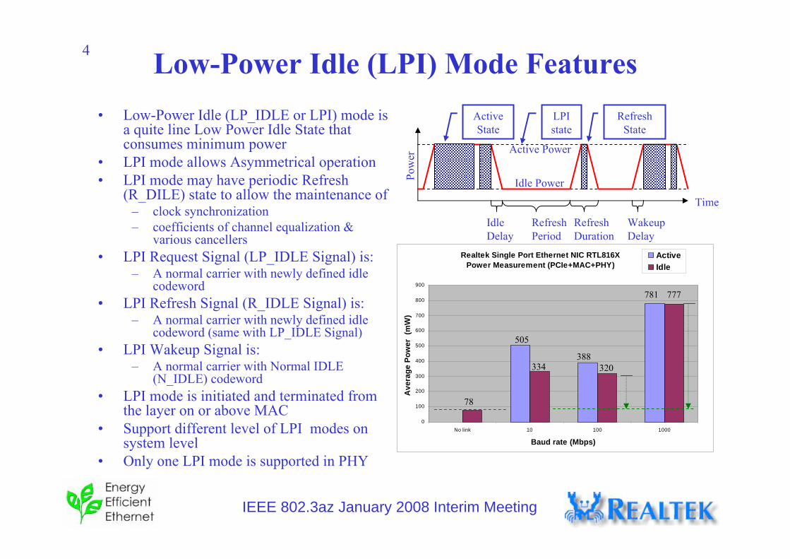
Low-Power Idle (LPI) Mode Features• Low-Power Idle (LP_IDLE or LPI) mode is
a quite line Low Power Idle State that consumes minimum power
• LPI mode allows Asymmetrical operation• LPI mode may have periodic Refresh
(R_DILE) state to allow the maintenance of – clock synchronization – coefficients of channel equalization &
various cancellers• LPI Request Signal (LP_IDLE Signal) is:
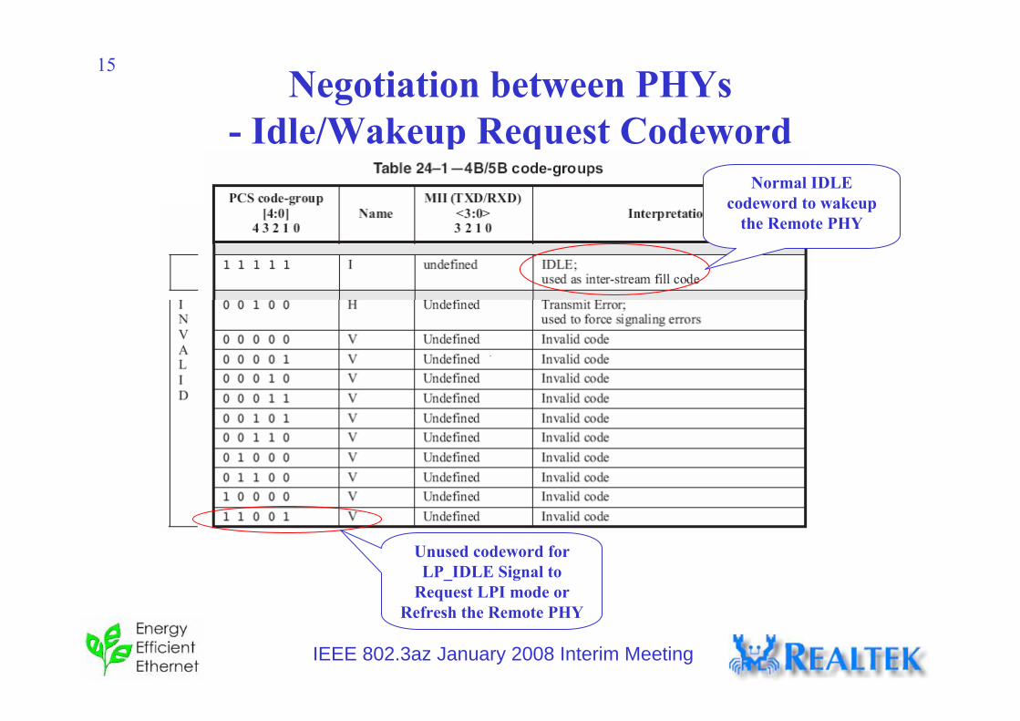
– A normal carrier with newly defined idle codeword
• LPI Refresh Signal (R_IDLE Signal) is:– A normal carrier with newly defined idle
codeword (same with LP_IDLE Signal)• LPI Wakeup Signal is:
– A normal carrier with Normal IDLE (N_IDLE) codeword
• LPI mode is initiated and terminated from the layer on or above MAC
• Support different level of LPI modes on system level
• Only one LPI mode is supported in PHY
78
320334388
505
777781
Active Power
Idle Power
Refresh Period
Idle Delay
Wakeup Delay
Pow
er
Time
RefreshState
LPI state
Active State
RefreshDuration
IEEE 802.3az January 2008 Interim Meeting
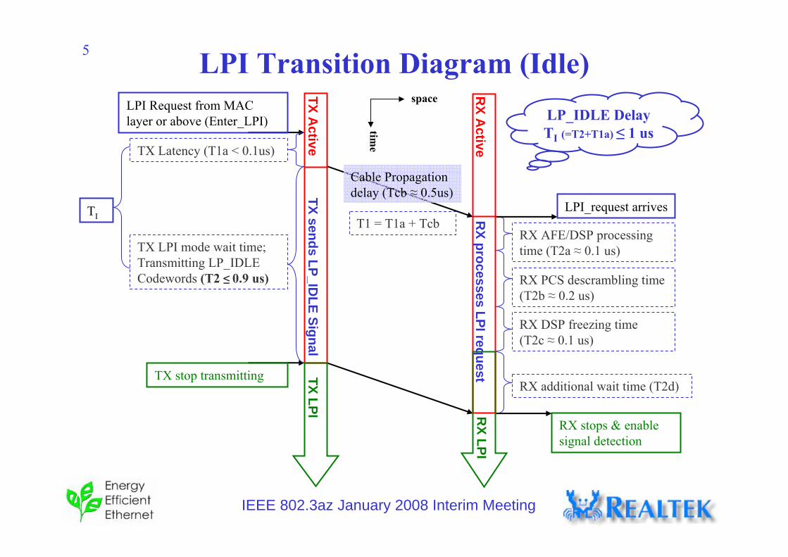
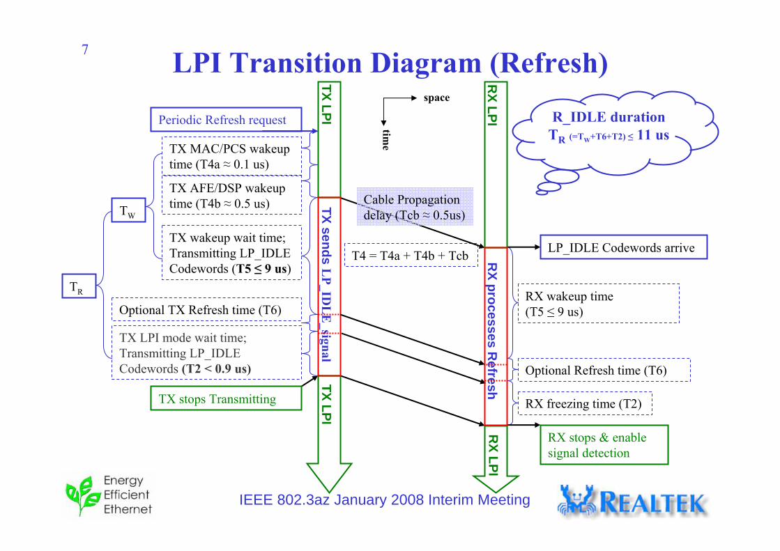
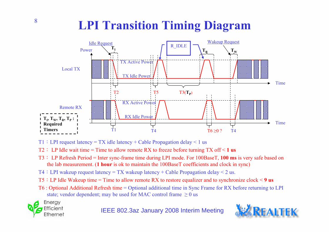
5 LPI Transition Diagram (Idle)LPI Request from MAC layer or above (Enter_LPI)
T1:LPI request latency = TX idle latency + Cable Propagation delay < 1 usT2: LP Idle wait time = Time to allow remote RX to freeze before turning TX off < 1 usT3: LP Refresh Period = Inter sync-frame time during LPI mode. For 100BaseT, 100 ms is very safe based on
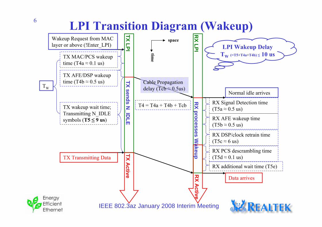
the lab measurement. (1 hour is ok to maintain the 100BaseT coefficients and clock in sync)T4:LPI wakeup request latency = TX wakeup latency + Cable Propagation delay < 2 us.T5:LP Idle Wakeup time = Time to allow remote RX to restore equalizer and to synchronize clock < 9 usT6 : Optional Additional Refresh time = Optional additional time in Sync Frame for RX before returning to LPI
state; vendor dependent; may be used for MAC control frame ≥ 0 us
TI, TW, TR, TP : Required Timers
Idle Request
Time
R_IDLE
TX Active Power
TX Idle PowerLocal TX
Remote RXRX Active Power
RX Idle Power
Power
Time
T2 T5
T6 ≥0 ?
T3(TP)
T1 T4
Wakeup Request
T4
TI TWTR
IEEE 802.3az January 2008 Interim Meeting
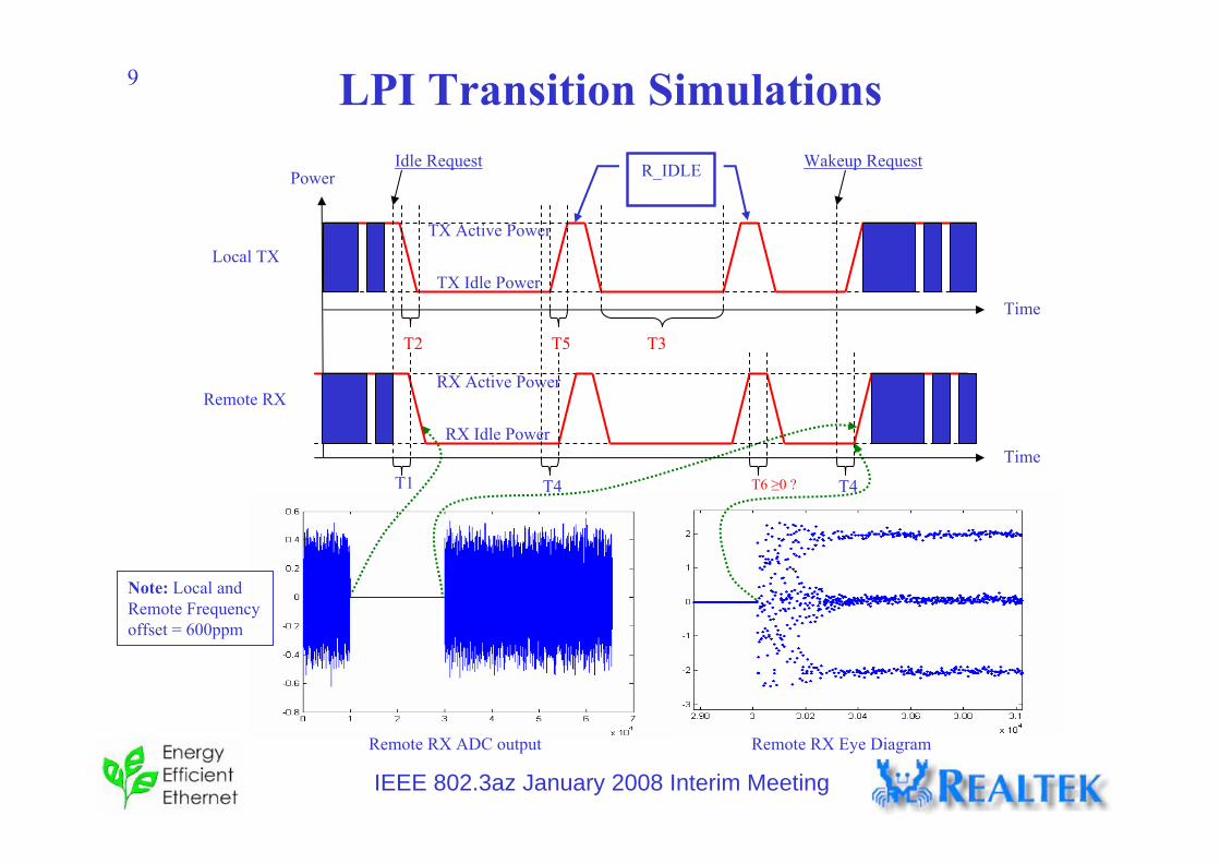
9 LPI Transition Simulations
Remote RX ADC output
Note: Local and Remote Frequency offset = 600ppm
Remote RX Eye Diagram
Idle Request
Time
R_IDLE
TX Active Power
TX Idle PowerLocal TX
Remote RXRX Active Power
RX Idle Power
Power
Time
T2 T5
T6 ≥0 ?
T3
T1 T4
Wakeup Request
T4
IEEE 802.3az January 2008 Interim Meeting
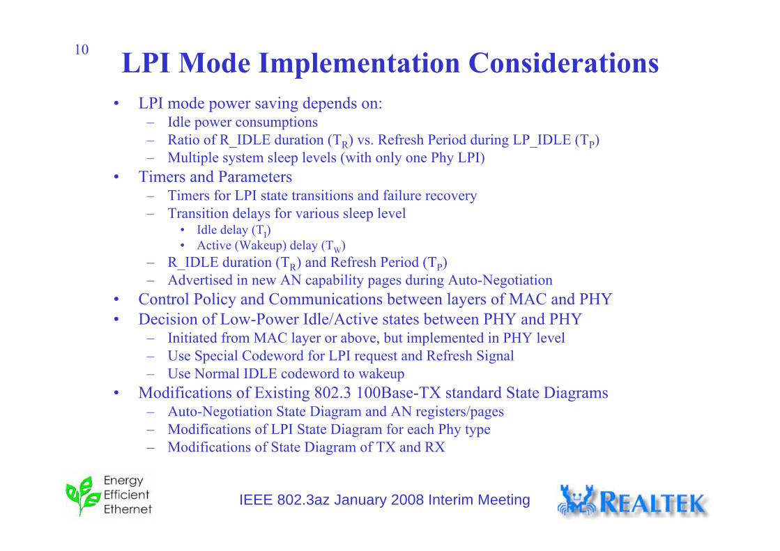
10 LPI Mode Implementation Considerations• LPI mode power saving depends on:
– Idle power consumptions– Ratio of R_IDLE duration (TR) vs. Refresh Period during LP_IDLE (TP)– Multiple system sleep levels (with only one Phy LPI)
• Timers and Parameters– Timers for LPI state transitions and failure recovery– Transition delays for various sleep level
• Idle delay (TI)• Active (Wakeup) delay (TW)
– R_IDLE duration (TR) and Refresh Period (TP)– Advertised in new AN capability pages during Auto-Negotiation
• Control Policy and Communications between layers of MAC and PHY• Decision of Low-Power Idle/Active states between PHY and PHY
– Initiated from MAC layer or above, but implemented in PHY level– Use Special Codeword for LPI request and Refresh Signal– Use Normal IDLE codeword to wakeup
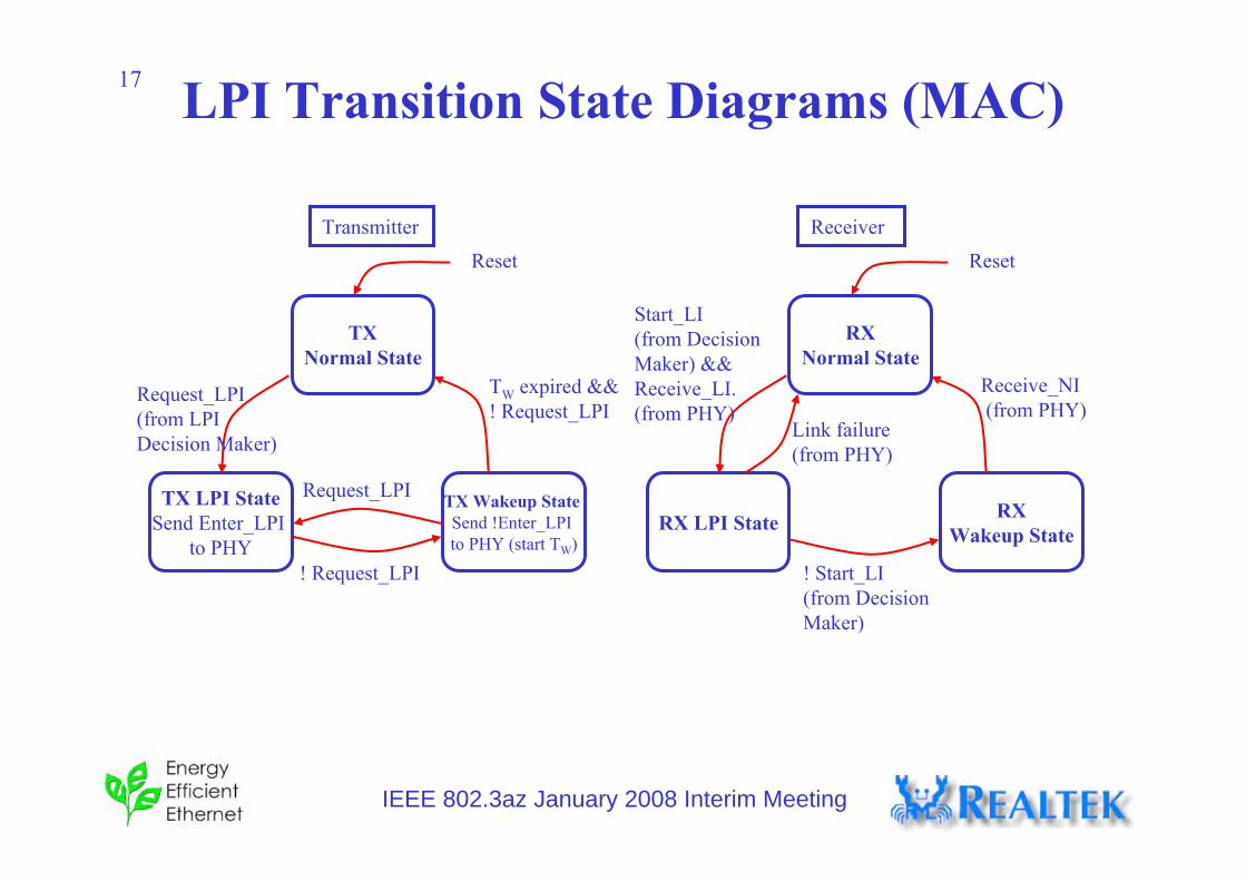
• Modifications of Existing 802.3 100Base-TX standard State Diagrams– Auto-Negotiation State Diagram and AN registers/pages– Modifications of LPI State Diagram for each Phy type – Modifications of State Diagram of TX and RX
IEEE 802.3az January 2008 Interim Meeting
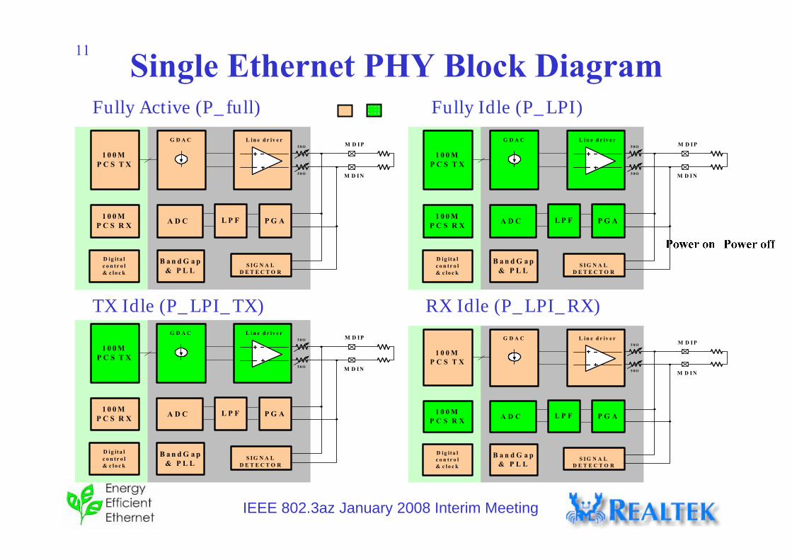
11 Single Ethernet PHY Block DiagramFully Active (P_full) Fully Idle (P_LPI)
TX Idle (P_LPI_TX) RX Idle (P_LPI_RX)
5 0 O
5 0 O
1 0 0 M P C S T X
G D A C L in e d r iv e rM D IP
M D IN
S IG N A LD E T E C T O R
L P FA D C P G A
B a n d G a p & P L L
1 0 0 M P C S R X
D ig ita l c o n tr o l & c lo c k
5 0 O
5 0 O
1 0 0 M P C S T X
G D A C L in e d r iv e rM D IP
M D IN
S IG N A LD E T E C T O R
L P FA D C P G A
B a n d G a p & P L L
1 0 0 M P C S R X
D ig ita l c o n tr o l & c lo c k
5 0 O
5 0 O
1 0 0 M P C S T X
G D A C L in e d r iv e rM D IP
M D IN
S IG N A LD E T E C T O R
L P FA D C P G A
B a n d G a p & P L L
1 0 0 M P C S R X
D ig ita l c o n tr o l & c lo c k
5 0 O
5 0 O
1 0 0 M P C S T X
G D A C L i n e d r iv e rM D I P
M D I N
S I G N A LD E T E C T O R
L P FA D C P G A
B a n d G a p & P L L
1 0 0 M P C S R X
D i g i t a l c o n t r o l & c l o c k
IEEE 802.3az January 2008 Interim Meeting
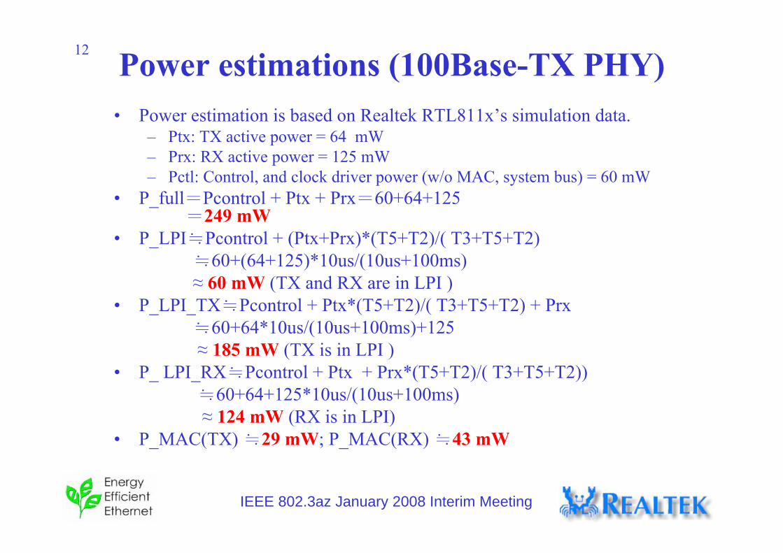
12 Power estimations (100Base-TX PHY)• Power estimation is based on Realtek RTL811x’s simulation data.
– Ptx: TX active power = 64 mW– Prx: RX active power = 125 mW– Pctl: Control, and clock driver power (w/o MAC, system bus) = 60 mW
• P_full=Pcontrol + Ptx + Prx=60+64+125=249 mW
• P_LPI≒Pcontrol + (Ptx+Prx)*(T5+T2)/( T3+T5+T2)≒60+(64+125)*10us/(10us+100ms)≈ 60 mW (TX and RX are in LPI )
• P_LPI_TX≒Pcontrol + Ptx*(T5+T2)/( T3+T5+T2) + Prx≒60+64*10us/(10us+100ms)+125 ≈ 185 mW (TX is in LPI )
• P_ LPI_RX≒Pcontrol + Ptx + Prx*(T5+T2)/( T3+T5+T2)) ≒60+64+125*10us/(10us+100ms) ≈ 124 mW (RX is in LPI)
• P_MAC(TX) ≒29 mW; P_MAC(RX) ≒43 mW
IEEE 802.3az January 2008 Interim Meeting
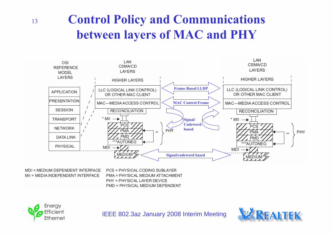
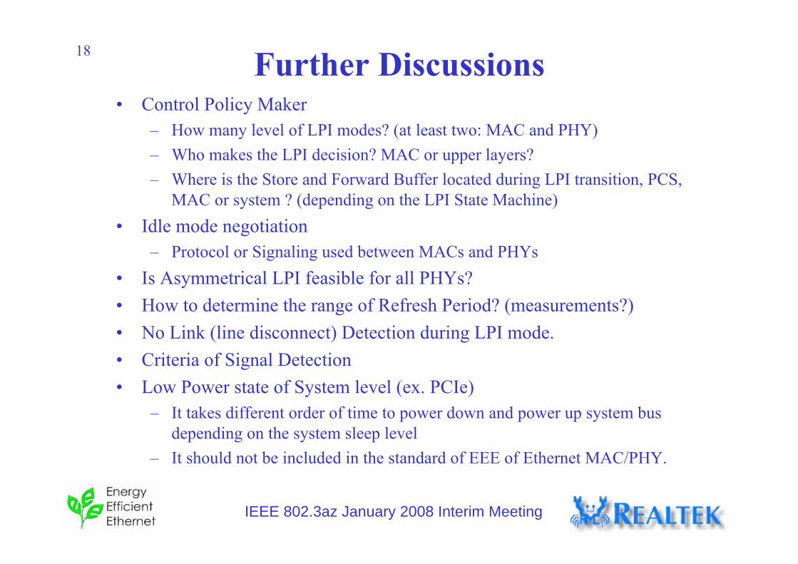
13 Control Policy and Communications between layers of MAC and PHY
– How many level of LPI modes? (at least two: MAC and PHY)– Who makes the LPI decision? MAC or upper layers? – Where is the Store and Forward Buffer located during LPI transition, PCS,
MAC or system ? (depending on the LPI State Machine)• Idle mode negotiation
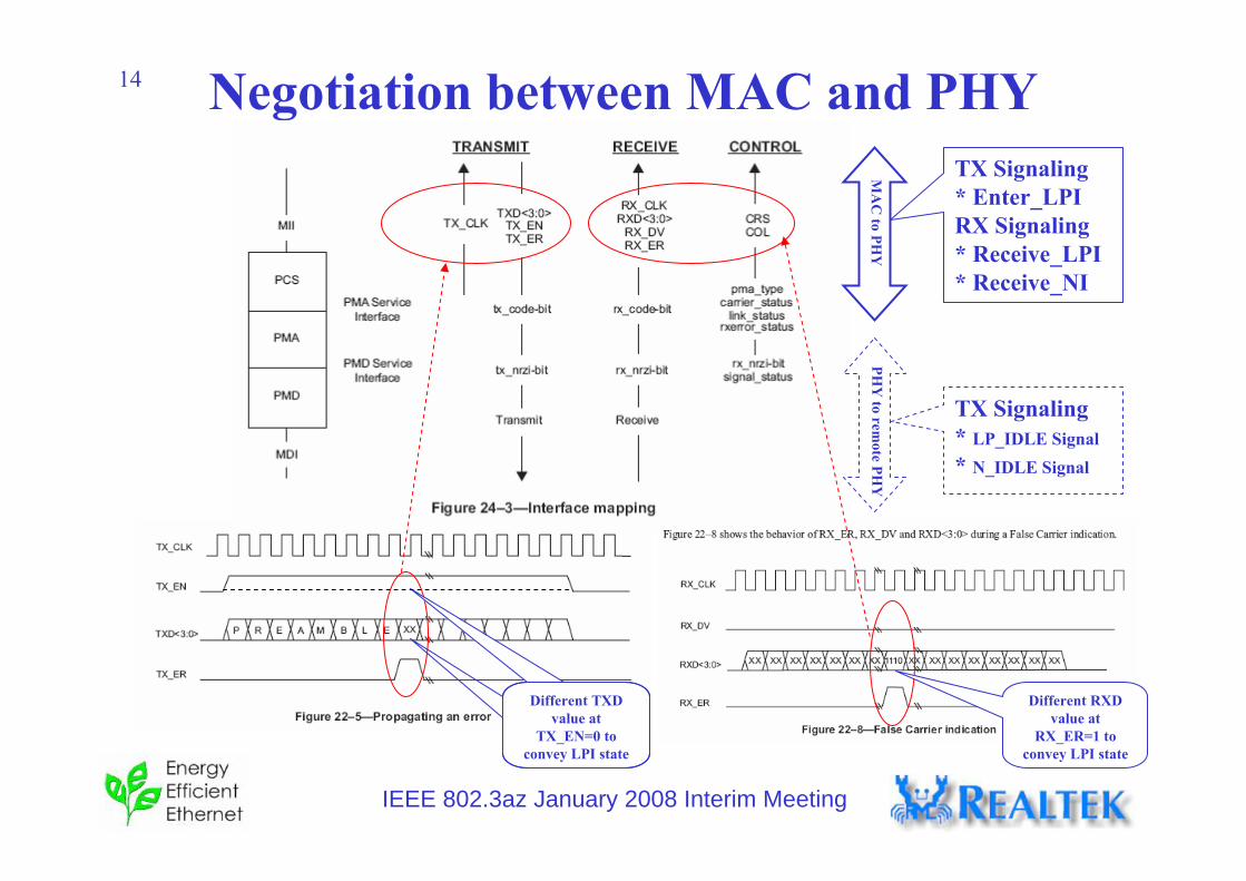
– Protocol or Signaling used between MACs and PHYs• Is Asymmetrical LPI feasible for all PHYs?• How to determine the range of Refresh Period? (measurements?)• No Link (line disconnect) Detection during LPI mode.• Criteria of Signal Detection• Low Power state of System level (ex. PCIe)
– It takes different order of time to power down and power up system bus depending on the system sleep level
– It should not be included in the standard of EEE of Ethernet MAC/PHY.
IEEE 802.3az January 2008 Interim Meeting
19
Questions?
Thank you
IEEE 802.3az January 2008 Interim Meeting
Backup
IEEE 802.3az January 2008 Interim Meeting
21
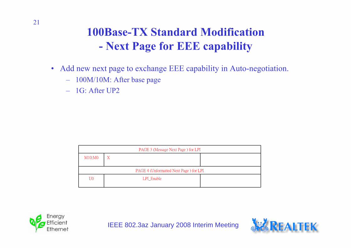
100Base-TX Standard Modification - Next Page for EEE capability
• Add new next page to exchange EEE capability in Auto-negotiation.– 100M/10M: After base page– 1G: After UP2
PAGE 3 (Message Next Page ) for LPI
M10:M0 X
PAGE 4 (Unformatted Next Page ) for LPI
U0 LPI_Enable
IEEE 802.3az January 2008 Interim Meeting
22 100Base-TX Standard Modification Auto Neg TX FSM
• Add stateEEE_MP_TX EEE_UP_TX
IEEE 802.3az January 2008 Interim Meeting
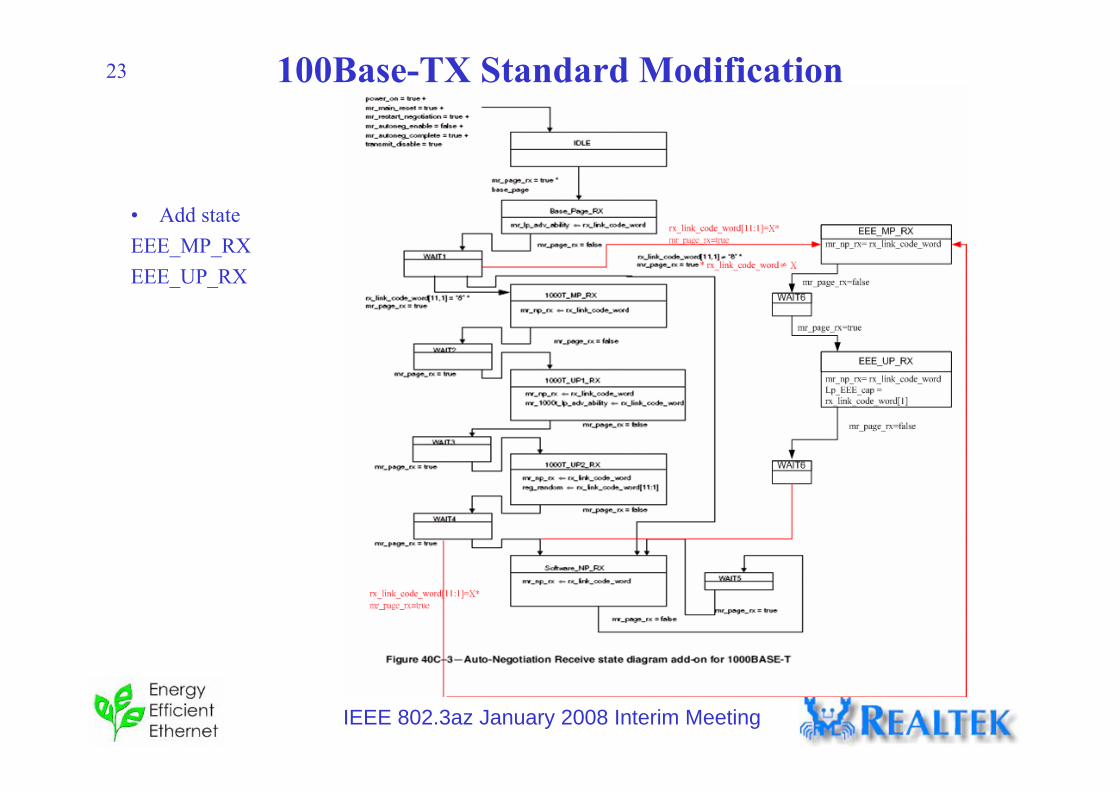
23 100Base-TX Standard Modification Auto Neg RX FSM
• Add state EEE_MP_RX EEE_UP_RX
IEEE 802.3az January 2008 Interim Meeting
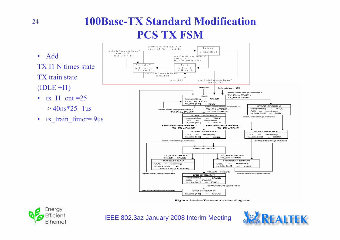
24 100Base-TX Standard ModificationPCS TX FSM
• Add TX I1 N times stateTX train state(IDLE +I1)• tx_I1_cnt =25
=> 40ns*25=1us• tx_train_timer= 9us
t x _ b i t s = I 1t x _ I 1 _ c n t = 0
T x I 1
t x _ b i t s = I D L E
T x t r a in
e n t e r _ L P I
s e n t C o d e G r o u p .i n d i c a t e *e n t e r _ L P I * t x _ I 1 _ c n t = 1 5
s e n t C o d e G r o u p . i n d i c a t e *! e n t e r _ L P I
t x _ I 1 _ c n t = t x_ I 1 _ c n t + 1
T x I1 C N T
s e n t C o d e G r o u p . i n d i c a t e *e n t e r _ L P I *
t x _ I 1 _ c n t ≠ 1 5
s e n t C o d e G r o u p . i n d i c a t e *e n t e r _ L P I
s e n t C o d e G r o u p . i n d i c a t *e n t e r _ L P I *t x _ t r a i n _ t i m e r _ d o n e
IEEE 802.3az January 2008 Interim Meeting
25 100Base-TX Standard ModificationPCS RX FSM
• Add Rx I1 state
R x I1
r x _ b i t s [ 9 : 0 ]≠ / I / J / ≠ / I / I1 /
≠ / I 1 / I1 /
r x _ b i t s [ 9 : 0 ] = / I / I 1 / + /I 1 / I 1 /
IEEE 802.3az January 2008 Interim Meeting
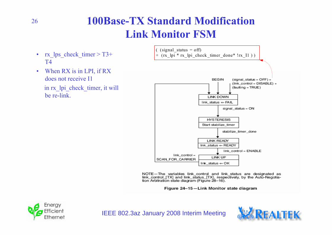
26 100Base-TX Standard ModificationLink Monitor FSM
• rx_lps_check_timer > T3+ T4
• When RX is in LPI, if RX does not receive I1 in rx_lpi_check_timer, it will be re-link.