54
Protocol Architectures IP Framework Going, Going…..

Protocol Architectures IP Framework
Going, Going…..

Course so far
• Basic OS principles • Networks - Ethernet • Network devices in Linux • Looked at socket code and basic socket
calls • Looked at the select socket call
– Call allows us to wait on a set of sockets – Alternative to forking another process or multi-
threading

Need to take a step back
• Moved from the OS to networking side. • Need to spend some time giving you a
networking context • Most communication models done using the
Open System Interconnection (OSI) model

OSI Model
Physical Layer
Data Link Layer
Network Layer
Transport Layer
Session Layer
Presentation Layer
Application Layer

OSI Model Explained
• Used as a reference model for computer communications. It is NOT an implementation model
• Physical Layer - interfaces with the physical medium. Decides things like what is a 1 and what is a 0.
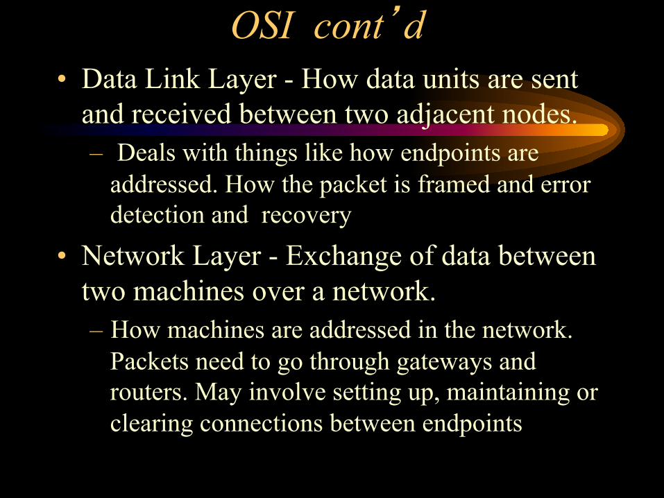
OSI cont’d • Data Link Layer - How data units are sent
and received between two adjacent nodes. – Deals with things like how endpoints are
addressed. How the packet is framed and error detection and recovery
• Network Layer - Exchange of data between two machines over a network. – How machines are addressed in the network.
Packets need to go through gateways and routers. May involve setting up, maintaining or clearing connections between endpoints

OSI Model • Transport Layer - Concerned with moving
data between two endpoints (usually two processes) over a network – Issues of reliability, error detection and
recovery as well as Quality-Of-Service issues • Session Layer - structures to support a
session - as a series of related interactions between endpoints. – Request/Response interaction - Client /Server;
PUSH/PULL models, how individual sessions are setup, maintained and closed
OSI Model Cont’d
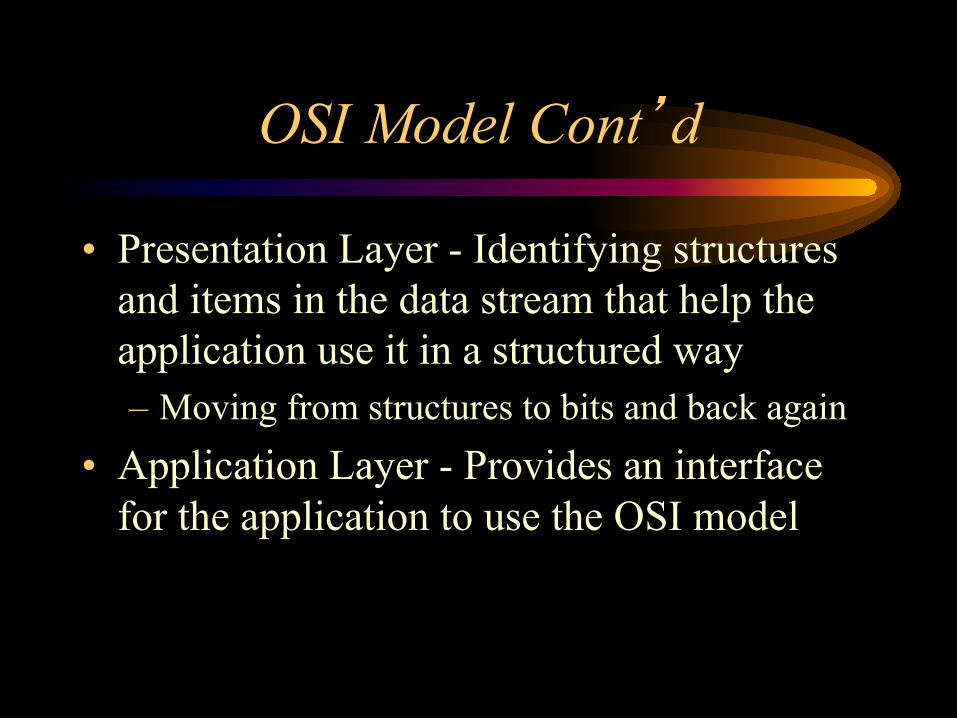
• Presentation Layer - Identifying structures and items in the data stream that help the application use it in a structured way – Moving from structures to bits and back again
• Application Layer - Provides an interface for the application to use the OSI model

IPv4 Header
32-bit source IP address
32-bit destination IP address
TOS TOTAL LENGTH IHL V
16-bit IDENTIFIER Flags 13-bit Frag Offset
TTL PROTO NO
16-bit header checksum
Options (if any)

IPv4 continued
• V = version number = 4 • IHL = IP header length in 32 bits = 5 • TOS = Type of Service Field
– used to specify quality-of-service requirements • TOTAL LENGTH = total length of packet • IDENTIFIER = uniquely identifies the
packet in a set
IPv4 continued
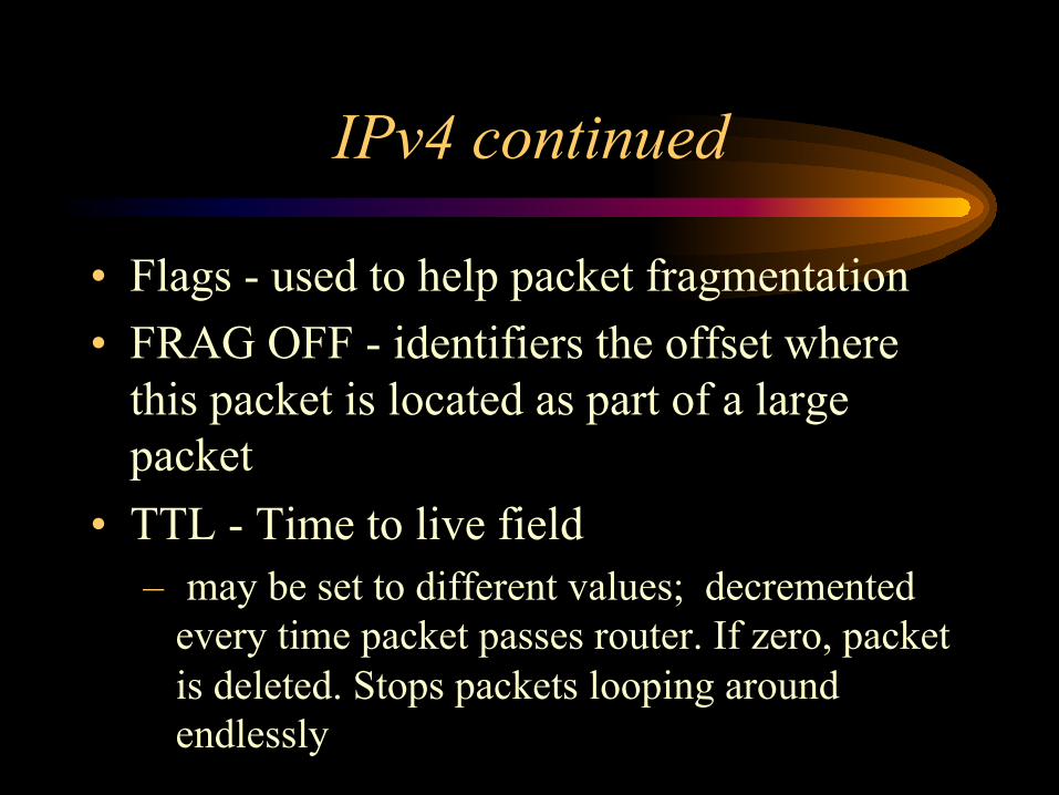
• Flags - used to help packet fragmentation • FRAG OFF - identifiers the offset where
this packet is located as part of a large packet
• TTL - Time to live field – may be set to different values; decremented
every time packet passes router. If zero, packet is deleted. Stops packets looping around endlessly

IPv4 continued
• PROTO_NO - specifies the transport protocol running over IP – TCP = 6, UDP = 17
• HEADER CHECKSUM - every header is first checksummed if error entire packet is discarded
• 32 -bit source and destination addresses

IPv6 Header Format Version Traffic
Class Flow Label
Payload Length Next header Hop Limit
Source Address
Destination Address
IPv6 Field Formats
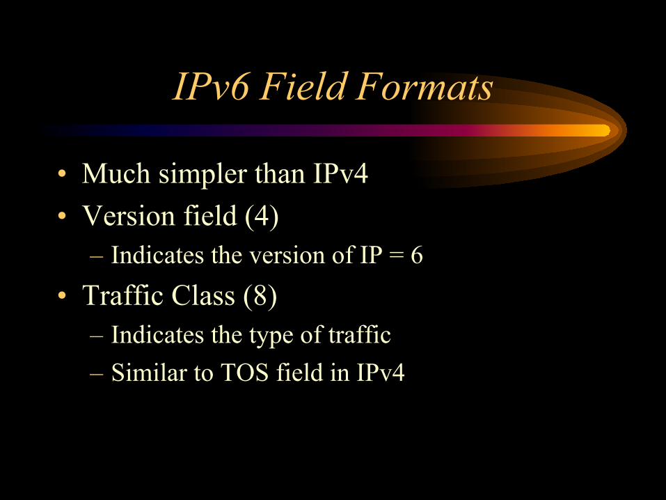
• Much simpler than IPv4 • Version field (4)
– Indicates the version of IP = 6 • Traffic Class (8)
– Indicates the type of traffic – Similar to TOS field in IPv4
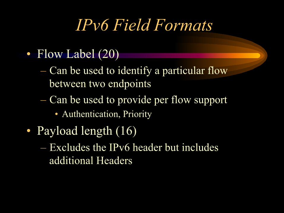
IPv6 Field Formats • Flow Label (20)
– Can be used to identify a particular flow between two endpoints
– Can be used to provide per flow support • Authentication, Priority
• Payload length (16) – Excludes the IPv6 header but includes
additional Headers

IPv6 Field Formats
• Next Header (8) – Additional Header – Transport Protocol
• TCP, UDP, etc
• Hop Limit (8) – Prevents Looping – Similar to TTL in IPv4

IPv6 Field Formats
• Source Address (128) • Destination Address (128) • Huge Address Space
– Divided into several types • Link Only (machines directly connected) • Site Only • Global Addresses

The Aggregatable Global Unicast Address
now obsolete
Interface Identifier SLAID NLAID RES TLAID Pre Fix
Prefix - 3 bits, 001 indicates an aggregatable global unicast address TLAID – 13 bits, Top-Level aggregatable idebtifier RES - 8 bits, Reserved for future use NLAID – 24 bits Next-level aggregatable identifier SLAID – 16 bits, Site-level aggregatable identifier Interface ID – 64 bits, Interface ID, globally unique

Auto-configuration
• Once we can determine the network that we are attached to, we can automatically get a unique IPv6 address
• Can do so using Router Advertisement and Neighbour Discovery protocols
• Eliminates the need for Foreign Agents • MN communicates directly with HA and
CN about Binding Updates

Header extensions
• Header extensions can be used to: – Help re-route packets, so avoid the need for
encapsulation – Can also provide security header extensions
which maintain secure connections
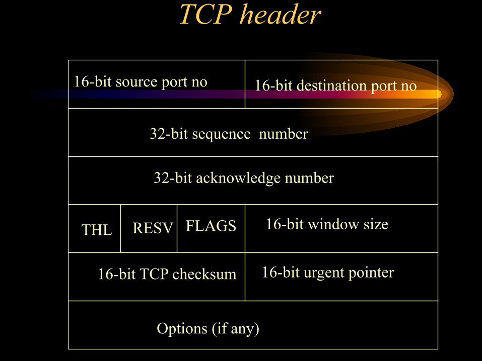
TCP header
Options (if any)
16-bit source port no 16-bit destination port no
32-bit sequence number
32-bit acknowledge number
16-bit window size
16-bit urgent pointer
THL FLAGS RESV
16-bit TCP checksum

TCP header
• 16-bit source and destination ports • 32-bit sequence no - refers to bytes sent • 32-bit acknowledge no - acknowledges
bytes received • THL - TCP header length • Window size - the number of bytes that the
sender can send to the receiver before waiting for an acknowledgement
TCP header cont’d
• TCP checksum - includes a pseudo IP header with IP source and destination addresses
• Urgent Pointer - points the urgent data in the stream
• RESV - reserved 6 bits

TCP Flags
• URG - urgent pointer is valid
• ACK - acknowledgement number is valid
• PSH - push packet up to application – end of a very large packet
• RST - reset packet - drop the connection

TCP Flags Cont’d
• SYN - synchronize sequence numbers at the start of a connection
• FIN - the sender is finished sending data
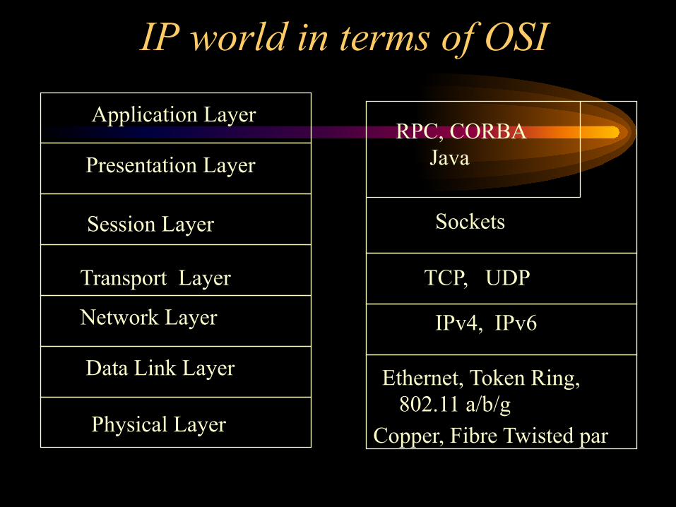
IP world in terms of OSI
Physical Layer
Data Link Layer
Network Layer
Transport Layer
Session Layer
Presentation Layer
Application Layer
Copper, Fibre Twisted par
IPv4, IPv6
TCP, UDP
Sockets
RPC, CORBA Java
Ethernet, Token Ring, 802.11 a/b/g

Mobility now a key issue
• Mobility is now getting ubiquitous • Explosion of wireless technologies
– Mobile phones • 2G, 2.5G, 3G ->>> 4G
• Wireless LANs – 802.11 based on Ethernet technology – Wireless ATM

New Wireless Technology coming
• Bluetooth – Now very common on PDAs, Laptops
• UltraWideband (UWB) – New Technology – First deployments
• 802.11n – Now being commonly deployed – Useable data speed about 200 Mbps

Wireless Infrastructure Two Extremes
• Fixed Wireless System – Endpoints are fixed but communicate over a wireless
link. • Ad-hoc systems
– No fixed infrastructure – Nodes communicate when they are within range of
each other transmissions. – MACs for these devices also look at power and ad-hoc
routing. Energy Aware Routing (EAR) protocols.

Mobile Systems • Mobile Systems – Most common
– One Endpoint normally fixed and part of the wired network
• Base stations – usually on hills or on tall buildings – Other endpoint moves – mobile Laptop, PDA, handset
• Horizontal Handoff – Handing off to another base station in the same network – Most common now
• Vertical Handoff – Handoff to a totally different network (e.g. – Will be common in the future

Main Problem in supporting mobility using IP
• An IP address provides two key inputs – It uniquely identifies the endpoint/device to the
network – It also is used to choose the path to route data
through the network – No inherent support for mobility

Implications for IP
• If we move from one network to another we need a completely new IP address associated with the new network to communicate
• However if we are on a completely new network, machines trying to communicate with us will be unaware that we have moved
• Need more infrastructure to support mobility – Mobile IPv4

Mobile IPv4 -The Terms
• Mobile Node (MN) – the mobile device • Corresponding Node (CN) – the device trying to
communicate with the MN • Home Network – the network by which the MN is
usually contacted • Home Agent (HA) – a network entity which keeps
track of the MN’s whereabouts and if the MN is away from its home network, forwards packets to the MN

Mobile IPv4 -The Terms cont’d
• Foreign Network – the network to which the device is currently connected – NOT its home network
• Care-of-Address (COA) – The address of the MN on the Foreign Network
• Foreign Agent (FA)- a network entity which keeps track of a visiting MN from another network

A Typical Setup
Internet
Home Network
Foreign Network CN’s Network
MN
Router HA
Router FA
MN/COA CN’s
Router
CN

Observations
• HA runs on Router of Home Network • FA runs on Router of Foreign Network • COA can be
– 1) A real IP address given to the MN • Co-location – limited number of IP addresses
– 2) An address managed by the FA • Not directly allocated to the MN

Problem
• How does the MN know it is now on a new network
• Routers advertise their presence on their networks. This is called a Router Advertisement or RA message
• HAs and FAs must also use messages to advertise their presence (RFC 1526)

RFC 1526 Type Code Checksum
# addresses Addr. Size Lifetime Router Address 1
Preference Level 1
Router Address 2 Preference Level 2
Type Length Sequence Number
COA
COA
Registration Lifetime Reserved R B H F M G V
:: :: :: :: ::

RFC 1526
Static part advertises router interfaces Mobile extension – used to advertise Home and
Foreign Agents H bit says that router can act as a home agent F bit says the router can act as a foreign agent R bit if set tells the MN to register with this agent
rather than getting a co-located address A list of COAs is also advertised

Getting a COA
• If the MN cannot hear any agent/router advertisements, it sends solicitation messages asking if an agent/router is available
• It can also try to obtain a co-located COA using standard means such as DHCP

Registration
• Now that it has a COA the MN must register this information with the Home Agent on its Home network
• If the COA has been obtained from the FA then the MN first registers with the FA and the FA in turn registers with the HA.

Registration Request 0 31
Type Flags Lifetime
Home Address
Home Agent
COA
Identification

What happens at the HA
• When HA receives a registration request: – Sets up a mobility binding which maps the
COA to the Home address of the MN – Sends a registration reply – All packets addressed to the MN using its
Home Address are now tunnelled to MN using its COA address.

Registration MN/COA FA HA
Registration
Registration
Mobility Binding
Registration Reply Registration Reply
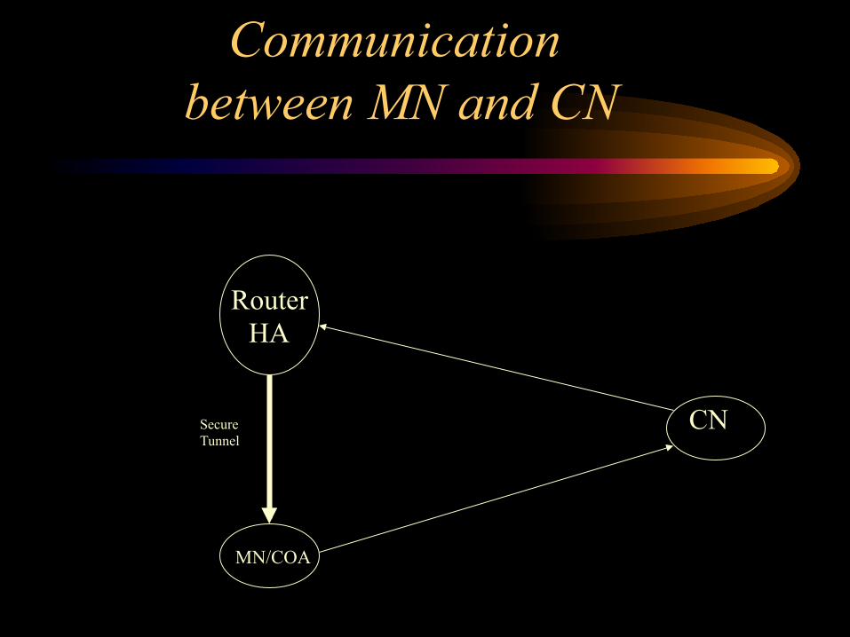
Mobile IPv4 Communication
between MN and CN
MN/COA
CN
Router HA
Secure Tunnel

Different Tunnelling Schemes
• IP-in-IP tunnelling – Outer IP header
• Src = IP address of the HA • Dest = IP address of the COA
– Inner IP header • Src = IP Address of the CN • Dest = IP Address of the MN at home

Other Encapsulation Schemes
• Minimum Encapsulation – Instead of using 2 IP headers we include the
two sets of addresses but eliminate the redundant bits - (M bit is set in RFC 1526)
• GRE Encapsulation – Supported by Cisco – Allows packets from one protocol suite to be
encapsulated using another protocol – (G bit is set in RFC 1526)

Big Problem
• If I, from the UK, go to a conference in Australia; at the conference I meet some one from France and we want to communicate using the Wireless LAN that has been set up for the conference.
• Packets get sent from Australia to France and the UK respectively and then back to Australia again

Route Optimisation
• Instead of sending data packets to the HA, the CN makes a Binding Request which asks for the COA of the MN. If OK, then the HA sends back current mobility binding for the MN
• The CN keeps a binding cache which is integrated with its routing table

Binding Update Protocol
• As the MN moves, it issues a Binding Update Message to its HA so that data can be sent to the new location
• Binding Updates (BU) can also be acknowledged to ensure that they have been received
• Binding Warning: If the MN moves to a new FA but packets are still being sent to the old FA, then a Binding Warning is sent back to the HA. The HA then informs the CN that the FA has been changed

CN HA FA_old MN FA_new Request
Update
ACK
MN moves
Data Data
Data
Data
Registration
Registration
Data Warning
Update
ACK
Update
ACK
Data Data
ROUTE OPTIMISATION – MOBILE IPv4
Verdict: Too complicated
• Binding Updates need to be communicated securely so that the MN movements are not tracked. Points to some sort of encryption
• Firewall and VPN issues as the MN moves around
• Is Mobile IPv6 any better?
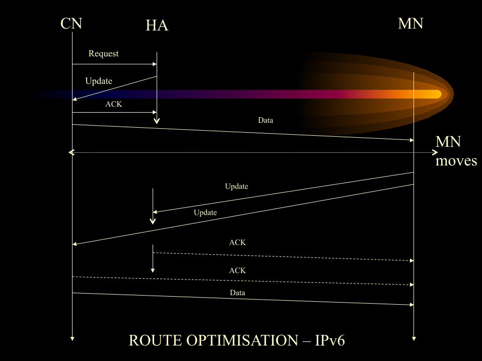
CN HA MN
Request
Update
ACK
MN moves
Data
Update
Update
ACK
ACK
Data
ROUTE OPTIMISATION – IPv6

Sources for this Lecture
• Internetworking with TCP/IP Volume III by Douglas Comer and David Stevens
• http://www.protocols.com A key site to find out about protocols and protocol stacks


