micromachines Article Proton Irradiation Effects on Hardness and the Volta Potential of Welding 308L Duplex Stainless Steel Baolong Jiang 1 , Qunjia Peng 2 , Zhijie Jiao 3 , Alex A. Volinsky 1,4 and Lijie Qiao 1, * 1 Beijing Advanced Innovation Center for Material Genetic Engineering, Key Laboratory for Environmental Fracture (MOE), University of Science and Technology Beijing, Beijing 100083, China; [email protected] (B.J.); [email protected] (A.A.V.) 2 Key Laboratory of Nuclear Materials and Safety Assessment, Institute of Metal Research, Chinese Academy of Sciences, Shenyang 110016, China; [email protected]3 Nuclear Engineering and Radiological Sciences, University of Michigan, 2355 Bonisteel Boulevard, Ann Arbor, MI 48109, USA; [email protected]4 Department of Mechanical Engineering, University of South Florida, Tampa, FL 33620, USA * Correspondence: [email protected]; Tel.: +86-10-6233-2345 Received: 28 November 2018; Accepted: 20 December 2018; Published: 25 December 2018 Abstract: 308L welding duplex stainless steel has been irradiated at 360 ◦ C with 2 MeV protons, corresponding to a dose of 3 dpa at the maximum depth of 20 μm. Microhardness of the δ-ferrite and austenite phases was studied before and after proton irradiation using in situ nanomechanical test system (ISNTS). The locations of the phases for indentations placement were obtained by scanning probe microscopy from the ISNTS. The hardness of the δ-ferrite had a close relationship with the vacancy distribution obtained from the Stopping and Range of Ions in Matter (SRIM) Monte Carlo simulation code. However, the hardness of the austenite phase in the maximum damage region (17–20 μm depth) from the SRIM simulation was decreasing sharply, and a hardness transition region (>20 μm and <55 μm depth) was found between the maximum damage region (17–20 μm depth) and the unirradiated region (>20 μm depth). However, the δ-ferrite hardness behavior was different. A hardness of the two phases increased on the irradiated surface and the interior due to different hardening mechanisms in the austenite and δ-ferrite phases after a long time high-temperature irradiation. A transition region (>20 μm and <55 μm depth) of the Volta potential was also found, which was caused by the deeper transfer of implanted protons measured by scanning Kelvin probe force microscopy. Keywords: 308L; proton irradiation; duplex microstructure; Volta potential; micro-hardness 1. Introduction Many devices are irradiated by various high-energy ions in the primary circuit environment of pressurized water reactors (PWR) [1–3]. Ionic bombardment can produce many defects in metals, and irradiation-induced material damage accumulates with prolonged equipment use [4]. One form of resulting damage is irradiation hardening. When metal is hardened by ion irradiation, it becomes more brittle. Therefore, some components, such as springs and fasteners, could break, causing damage to larger parts if not replaced [5,6]. Irradiation-assisted stress corrosion cracking is also a concerning problem [7–9]. Additionally, irradiation hardening could produce local stress concentrations, which greatly enhance the stress corrosion cracking. At present, various studies of irradiation hardening have been conducted using austenite stainless steels (face-centered cubic, fcc), such as 304L and 316L, which are widely used as nuclear structural materials [10–12]. In addition, other nuclear materials, including oxide dispersion strengthened steels (body-centered cubic, bcc) [13,14], vanadium Micromachines 2019, 10, 11; doi:10.3390/mi10010011 www.mdpi.com/journal/micromachines
Transcript
micromachines
Article
Proton Irradiation Effects on Hardness and the VoltaPotential of Welding 308L Duplex Stainless Steel
Baolong Jiang 1 , Qunjia Peng 2, Zhijie Jiao 3, Alex A. Volinsky 1,4 and Lijie Qiao 1,*1 Beijing Advanced Innovation Center for Material Genetic Engineering, Key Laboratory for Environmental
Fracture (MOE), University of Science and Technology Beijing, Beijing 100083, China;[email protected] (B.J.); [email protected] (A.A.V.)
2 Key Laboratory of Nuclear Materials and Safety Assessment, Institute of Metal Research,Chinese Academy of Sciences, Shenyang 110016, China; [email protected]
3 Nuclear Engineering and Radiological Sciences, University of Michigan, 2355 Bonisteel Boulevard,Ann Arbor, MI 48109, USA; [email protected]
4 Department of Mechanical Engineering, University of South Florida, Tampa, FL 33620, USA* Correspondence: [email protected]; Tel.: +86-10-6233-2345
Received: 28 November 2018; Accepted: 20 December 2018; Published: 25 December 2018 �����������������
Abstract: 308L welding duplex stainless steel has been irradiated at 360 ◦C with 2 MeV protons,corresponding to a dose of 3 dpa at the maximum depth of 20 µm. Microhardness of the δ-ferrite andaustenite phases was studied before and after proton irradiation using in situ nanomechanical testsystem (ISNTS). The locations of the phases for indentations placement were obtained by scanningprobe microscopy from the ISNTS. The hardness of the δ-ferrite had a close relationship with thevacancy distribution obtained from the Stopping and Range of Ions in Matter (SRIM) Monte Carlosimulation code. However, the hardness of the austenite phase in the maximum damage region(17–20 µm depth) from the SRIM simulation was decreasing sharply, and a hardness transition region(>20 µm and <55 µm depth) was found between the maximum damage region (17–20 µm depth)and the unirradiated region (>20 µm depth). However, the δ-ferrite hardness behavior was different.A hardness of the two phases increased on the irradiated surface and the interior due to differenthardening mechanisms in the austenite and δ-ferrite phases after a long time high-temperatureirradiation. A transition region (>20 µm and <55 µm depth) of the Volta potential was also found,which was caused by the deeper transfer of implanted protons measured by scanning Kelvin probeforce microscopy.
Keywords: 308L; proton irradiation; duplex microstructure; Volta potential; micro-hardness
1. Introduction
Many devices are irradiated by various high-energy ions in the primary circuit environment ofpressurized water reactors (PWR) [1–3]. Ionic bombardment can produce many defects in metals,and irradiation-induced material damage accumulates with prolonged equipment use [4]. One formof resulting damage is irradiation hardening. When metal is hardened by ion irradiation, it becomesmore brittle. Therefore, some components, such as springs and fasteners, could break, causing damageto larger parts if not replaced [5,6]. Irradiation-assisted stress corrosion cracking is also a concerningproblem [7–9]. Additionally, irradiation hardening could produce local stress concentrations,which greatly enhance the stress corrosion cracking. At present, various studies of irradiationhardening have been conducted using austenite stainless steels (face-centered cubic, fcc), such as 304Land 316L, which are widely used as nuclear structural materials [10–12]. In addition, other nuclearmaterials, including oxide dispersion strengthened steels (body-centered cubic, bcc) [13,14], vanadium
alloys [15], high-entropy alloys and reactor pressure vessels (RPV) steels have also been studied [16–20].Many factors, which affect irradiation hardness have been considered, including irradiation dose,temperature, and defect types. However, defect types are most important, as the temperature of PWRis 300–400 ◦C in different circuits and hardening tends to saturate at some radiation doses [21–23].It can be concluded that irradiation hardening has a close relationship with defect types formed in thebulk when the irradiation dose is below saturation.
308L stainless steel welded overlay cladding is used on the surface of RPV to protectit from corrosion in a water environment. It has approximately 10% δ-ferrite phase (bcc)and 90% austenite phase (fcc), which are subjected to strong ion irradiation from the reactorcore [24]. Takeuchi et al. [24,25] investigated the effects of thermal aging and neutron irradiation onmicrostructure and hardness of 308L steel using atom probe tomography and nanoindentation testing.They found that the primary factors responsible for the hardening of the δ-ferrite phase are Cr spinodaldecomposition and NiSiMn clusters formed by thermal aging [26,27]. Furthermore, the hardeningof the δ-ferrite phase occurred due to both irradiation and aging, since the Cr concentration in theδ-ferrite phase is enhanced by irradiation [27]. However, the NiSi clusters formed by irradiation onlycause hardening of the austenite phase [28].
It is also noticeable that hardening mechanisms of ferrite and austenite are different according tothe Hall-Petch formula σy = σ0 + Ky·d−1/2 [29] due to the relationship between the lattice frictionalresistance (σ0), dislocation pinning force (Ky), yield strength (σy), and radiation dose. In bcc metals,only σ0 changes significantly with increasing radiation dose. Therefore, lattice friction hardeningmechanisms are mainly found in irradiated bcc materials, while fcc materials collectively suffer fromlattice friction hardening and source hardening, since both σ0 and Ky are affected by the irradiationdose. Chen et al. [30,31] studied the defects formed after irradiation of the cast austenitic stainless steel(CASS) CF8 cast stainless steel, which has both austenite and δ-ferrite phases. It has been observedthat different kinds of defects formed in the material when various phase structures were irradiated byheavy ions. At a high dose of three displacements per atom (dpa), a dislocation network formed inthe fcc structure, while the bcc structure exhibited extended dislocations as line segments. One couldmake a preliminary judgment that the irradiation hardening of different structural materials has astrong relationship with defect types formed in them, and the hardening mechanisms can be changedwith different irradiation doses.
Thus, most studies of irradiation hardening are focused on single phase steels, with less emphasison duplex steels. Some studies considered uniform damage region of the duplex steels [32]. The surfaceis exposed to the environment and the maximum damage region has many more dpa than the uniformdamage region, which could simulate the 40 years operation under irradiation conditions [33]. Thesurface and the maximum damage regions along the depth direction should also be considered andstudied systematically in addition to the uniform damage region. Most irradiation experimentswere carried out using protons substitutes for neutrons because the radiation damage effects causedby neutrons are close to protons [34]. However, when metal is implanted by high energy protons,a transition region of protons exists in the unirradiated region exceeding the irradiated depth and thespecific depth of this region has not been determined by any effective means [35,36].
Scanning Kelvin probe force microscopy (SKPFM) is an effective method to detect hydrogen bymapping the contact potential difference (CPD) changes and has been increasingly used in corrosionstudies [37]. Guo et al. observed the hydrogen-induced CPD changes in duplex stainless steel (DSS)due to different hydrogen solubility and investigated DSS pitting corrosion behavior using SKPFM [38].In addition, Stratmann et al. also reported that CPD had a linear relation with the corrosion potential atthe metal-solution interface [39,40]. SKPFM can directly measure the change of hydrogen concentration.Therefore, the unirradiated region along the depth of the irradiated sample should also be studiedby SKPFM.
In this paper, 308L stainless steel has been studied. 308L stainless steel is used as a weldingmaterial in the primary loop of pressurized water reactors because it exhibits enhanced corrosion
Micromachines 2019, 10, 11 3 of 13
resistance due to its duplex phase structure [41,42]. Nanoindentation was used to investigatehardening of austenite and δ-ferrite caused by proton irradiation. Surface, uniform, maximumdamage, and unirradiated regions along the depth direction of the irradiated sample were usedfor hardness testing. In addition, the transition region of protons was directly measured by SKPFMin the unirradiated region past the irradiated depth. Thus, the specific depth of the transition regionwas obtained.
2. Materials and Methods
The material used for the experiments is 308L duplex stainless steel. The hard-facing layer wascut from a mockup of a safe-end weld with a nominal chemical composition of 68% Fe, 19.88% Cr,10.3% Ni, 1.33% Mn, 0.32% Si, 0.065% Cu, 0.016% C, 0.015% P, 0.011% S, and 0.01% Nb, in wt%.The samples were in the form of rectangular bars with 20 × 3 × 2 mm size, which were cut fromthe weld joint for proton irradiation. The upper-end surface of the sample before irradiation wasmechanically ground by silicon carbide paper up to 5000 grit, then polished using 0.5 µm diamondpaste, and finally polished by 0.04 µm colloidal silica slurry. Finally, the stress layer was removed fromthe surface, and the samples were ultrasonically cleaned in ethanol. Pure nickel used for calibration asa standard sample was polished up to 2000 grit with SiC paper in water and ultrasonically cleaned indistilled water.
Proton irradiation was performed using a custom-designed stage connected to the General IonexTandetron accelerator at the Michigan Ion Beam Laboratory. Irradiation experiments were conductedusing 2 MeV protons at a dose rate of approximately 6 × 10⁻⁶ dpa/s, resulting in nearly uniformdamage throughout the first 15 µm of the 20 µm proton depth range. The experimental doses and doserates were calculated using the stopping and range of ions in matter (SRIM 2008, formerly Transportof Ions in Mater, TRIM) Monte Carlo simulation code. The displacements per atom were calculatedusing the SRIM with a displacement energy of 40 eV, as recommended in the ASTM E521-8 [43–45].The irradiated surface area was approximately 60 mm2. The specimen temperature was maintainedduring irradiation at 360 ± 5 ◦C.
Microhardness was measured by the in situ nanomechanical test system (Hysitron,TI-900 Triboindenter, Minneapolis, MN, USA). Scanning probe microscopy (SPM) imaging and in situhardness measurements were carried out using a contact mode to record the surface topography withthe Berkovich tip. From the topography of the δ-ferrite and austenite phases, the δ-ferrite had a verynarrow size of 3–5 µm. Therefore, the 1500 µN maximum load was used to measure hardness andavoid indentation depth in excess of the δ-ferrite width.
SKPFM is one of the modes of SPM, which can detect the Volta potential of the material. DimensionNanoscope V (Veeco Instruments Inc., New York, NY, USA) was used for the SKPFM measurements.To avoid environmental effects, the SKPFM measurements were conducted in air at room temperatureand relative humidity of about 25%. The tip used in the SKPFM measurements was the NT-MDTconductive TiN-coated silicon tip (Moscow, Russia) with 2.5 N/m force constant and 35 nm tipradius. The lift mode was used to record the Volta potential signal at 60 nm distance from the samplesurface [46].
In the SKPFM measurements, AC voltage is applied to biased oscillating conductive tip [47,48].The topography and the Volta potential were detected by normal atomic force microscopy (AFM)detection scheme. After that, a reverse DC voltage with the same magnitude was applied to the tip tomake up the difference of AC voltage and stop the tip oscillation. Finally, the signal was inverted bythe output signal from the instrument. In SKPFM, the contact potential difference was calculated as thedifference between the tip and the sample voltage: VCPD = (φtip − φsample)/e, where φtip and φsampleare the work functions of the tip and the sample, and e is the electron charge. From the work function ofthe tip (φtip), the work function of the sample (φsample) can be deduced. The work functions have beenused for calculating the corrosion rates [49]. Many experimental observations and theoretical studiesindicated that the work function has a close relationship with the corrosion potential. The lower the
Micromachines 2019, 10, 11 4 of 13
work function of the material, the easier it corrodes, so that the work function is a sensitive parameterreflecting corrosion behavior [50,51].
The detected Volta potential values are also influenced by the tip characteristics, such as the metalcoating and the probe geometry. In order to avoid the corresponding errors, a calibration experimentof the Volta potential was carried out using a pure Ni surface with the stable known potential [52].
3. Results
3.1. Proton Irradiation Effects on Hardening of Different Regions
3.1.1. Irradiation Regions from the SRIM Simulation Curves
The proton distribution and the profile of radiation-induced displacement per atom weregenerated using the SRIM code for the 2 MeV protons, as shown in Figure 1. The dpa (vacanciesproduced/atom = displacements per atom) and atomic implantation ion concentration (in at%) wereobtained by using Equations (1) and (2) [53]. As shown in Figure 1, four regions were selected formeasurements after proton irradiation. One was the surface region I of the irradiated sample, the nextwas the uniform damage region II, the third was the maximum damage region III of implanted ionsand vacancies in the final irradiated depth and the last was the unirradiated region IV deeper inthe sample, listed in Table 1. At the initial stage, four measurement regions were obtained from theSRIM simulation curves, while the unirradiated region along the depth direction could be dividedinto two regions, including a region affected by protons and another region unaffected by irradiation,which would be characterized by nanoindentation and SKPFM in the next section of this study.
Micromachines 2018, 9, x 4 of 13
experiment of the Volta potential was carried out using a pure Ni surface with the stable known potential [52].
3. Results
3.1. Proton Irradiation Effects on Hardening of Different Regions
3.1.1. Irradiation Regions from the SRIM Simulation Curves
The proton distribution and the profile of radiation‐induced displacement per atom were generated using the SRIM code for the 2 MeV protons, as shown in Figure 1. The dpa (vacancies produced/atom = displacements per atom) and atomic implantation ion concentration (in at%) were obtained by using Equations (1) and (2) [53]. As shown in Figure 1, four regions were selected for measurements after proton irradiation. One was the surface region I of the irradiated sample, the next was the uniform damage region II, the third was the maximum damage region III of implanted ions and vacancies in the final irradiated depth and the last was the unirradiated region IV deeper in the sample, listed in Table 1. At the initial stage, four measurement regions were obtained from the SRIM simulation curves, while the unirradiated region along the depth direction could be divided into two regions, including a region affected by protons and another region unaffected by irradiation, which would be characterized by nanoindentation and SKPFM in the next section of this study.
Figure 1. SRIM 2008 simulation of the damage zone and implanted protons distribution: region I at the surface; region II, uniform damage; region III, maximum damage; and IV, unirradiated region along the sample depth.
Table 1. Regions affected by vacancies and implanted protons.
Region position in the sample
Regions affected by vacancies and protons Depth, μm Region number
Surface Surface damage region 0 I
Interior
Uniform damage region 0–17 II
Maximum damage region 17–20 III
Transition region 20–55 IV
Figure 1. SRIM 2008 simulation of the damage zone and implanted protons distribution: region I at thesurface; region II, uniform damage; region III, maximum damage; and IV, unirradiated region alongthe sample depth.
Table 1. Regions affected by vacancies and implanted protons.
Region Position inthe Sample
Regions Affected byVacancies and Protons Depth, µm Region Number
Surface Surface damage region 0 I
Interior
Uniform damage region 0–17 II
Maximum damage region 17–20 III
Transition region(hardness and potential) 20–55
IV
Region unaffected byirradiation >55
Micromachines 2019, 10, 11 5 of 13
3.1.2. Ferrite and Austenite Microhardness
Figure 2a shows the unirradiated δ-ferrite and austenite topography of the 308L steel measuredby SPM. It is seen that the δ-ferrite phase has a much smaller size than the γ-austenite phase and theindentation point could be at the boundary of the two phases due to the thermal drift. In order to avoidthermal drift effects, at least five indentations were performed to calculate the average hardness of eachphase. Figure 2b shows representative indentation load-displacement curves of the two unirradiatedphases. The hardness of δ-ferrite was higher than austenite at the same maximum load of 1500 µNsince austenite had larger indentation depth for the same maximum load [54]. The average hardnessfor each phase is: unirradiated δ-ferrite 5.62 ± 0.34 GPa and unirradiated austenite 4.09 ± 0.23 GPa.
Micromachines 2018, 9, x 5 of 13
(hardness and potential)
Region unaffected by irradiation >55
3.1.2. Ferrite and Austenite Microhardness
Figure 2a shows the unirradiated δ‐ferrite and austenite topography of the 308L steel measured by SPM. It is seen that the δ‐ferrite phase has a much smaller size than the γ‐austenite phase and the indentation point could be at the boundary of the two phases due to the thermal drift. In order to avoid thermal drift effects, at least five indentations were performed to calculate the average hardness of each phase. Figure 2b shows representative indentation load‐displacement curves of the two unirradiated phases. The hardness of δ‐ferrite was higher than austenite at the same maximum load of 1500 μN since austenite had larger indentation depth for the same maximum load [54]. The average hardness for each phase is: unirradiated δ‐ferrite 5.62 ± 0.34 GPa and unirradiated austenite 4.09 ± 0.23 GPa.
Figure 2. (a) SPM surface topography of unirradiated austenite and ferrite phases; and (b) nanoindentation load‐displacement curves of the two phases in (a).
Figure 3 shows the cross‐sectional SEM image of the irradiated sample after colloidal silica slurry polishing. A clear boundary was found in the irradiated and unirradiated regions after polishing with colloidal silica slurry. This line is the irradiation boundary (region III). In addition, the δ‐ferrite phase was stretched across the sagged austenite phase in the irradiation boundary after polishing. This result indicated that the δ‐ferrite phase was harder than the austenite in this region, also confirmed by the nanoindentation hardness measurements: δ‐ferrite 6.8 ± 0.40 GPa > austenite 2.78 ± 0.08 GPa. The austenite in the boundary region III has the lowest hardness. The δ‐ferrite in the boundary has the maximum hardness compared with any other region.
(b) (a)
20 μm
δ γ
Figure 2. (a) SPM surface topography of unirradiated austenite and ferrite phases; and (b) nanoindentationload-displacement curves of the two phases in (a).
Figure 3 shows the cross-sectional SEM image of the irradiated sample after colloidal silica slurrypolishing. A clear boundary was found in the irradiated and unirradiated regions after polishingwith colloidal silica slurry. This line is the irradiation boundary (region III). In addition, the δ-ferritephase was stretched across the sagged austenite phase in the irradiation boundary after polishing.This result indicated that the δ-ferrite phase was harder than the austenite in this region, also confirmedby the nanoindentation hardness measurements: δ-ferrite 6.8 ± 0.40 GPa > austenite 2.78 ± 0.08 GPa.The austenite in the boundary region III has the lowest hardness. The δ-ferrite in the boundary has themaximum hardness compared with any other region.Micromachines 2018, 9, x 6 of 13
Figure 3. SEM image of the irradiated sample cross‐section after colloidal silica slurry polishing including five regions: irradiated surface region I, uniform damage region II, maximum damage region III, and unirradiated region IV along the depth direction.
3.1.3. SKPFM Volta Potential of the Irradiated Sample Cross‐Section
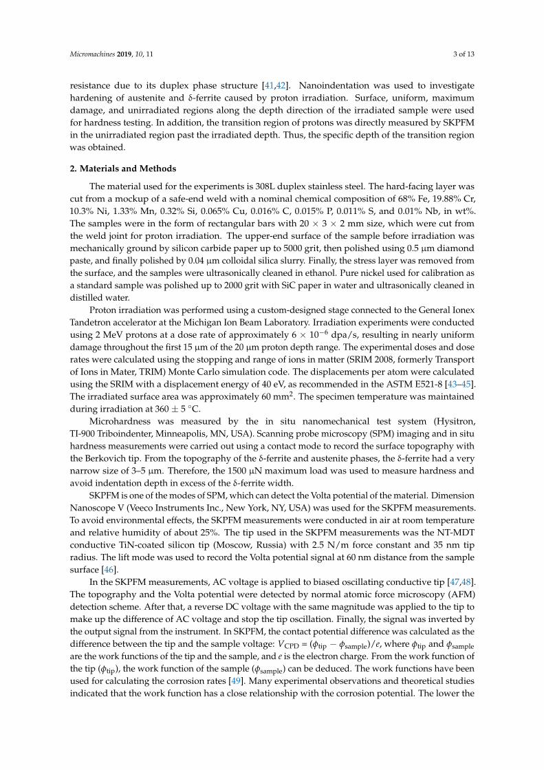
Figure 4a shows the Volta potential changes with depth from 10 μm to 80 μm below the irradiated surface. Figure 4b presents the corresponding Volta potential and height topography maps. It can be observed that the transition region IV of the Volta potential formed in the unirradiated region below the irradiated region. The depth of the Volta potential transition region was approximately 35 μm. In addition, the transition region of hardness has also been found in austenite in the same region of the Volta potential transition, as shown in Figure 4c,d. Hardness values were obtained every 3 μm from the nanoindentation measurements, and at least two indentation points were used for hardness testing at each depth, as shown in Figure 4c. The hardness values of the transition region were obtained by taking the average value of all indentation points in this region, as shown in Figure 4d.
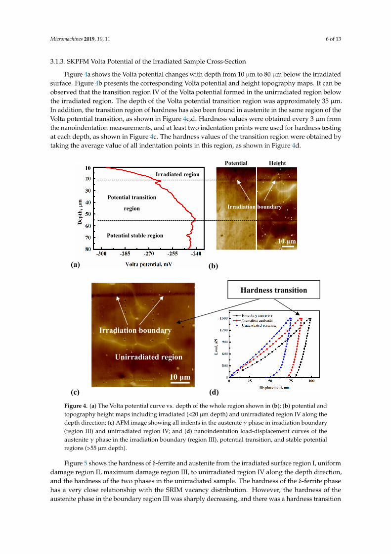
Figure 5 shows the hardness of δ‐ferrite and austenite from the irradiated surface region I, uniform damage region II, maximum damage region III, to unirradiated region IV along the depth direction, and the hardness of the two phases in the unirradiated sample. The hardness of the δ‐ferrite phase has a very close relationship with the SRIM vacancy distribution. However, the hardness of the austenite phase in the boundary region III was sharply decreasing, and there was a hardness transition region from the boundary region III to the unirradiated region IV. In order to ensure that the test region exceeds the region affected by hydrogen ions, the surface data of the samples hardness without irradiation was compared to the region unaffected by irradiation in the depth direction. It was observed that the region exceeding the transition region depth has the same hardness as the unirradiated surface.
II, 0–17 μm depth
III, 17–20 μm depth
IV, >20 μm depth
Ferrite phases in the irradiation boundary region
4 μm
Irradiation boundary
20 μm irradiation depth
I, 0 μm depth
Figure 3. SEM image of the irradiated sample cross-section after colloidal silica slurry polishingincluding five regions: irradiated surface region I, uniform damage region II, maximum damage regionIII, and unirradiated region IV along the depth direction.
Micromachines 2019, 10, 11 6 of 13
3.1.3. SKPFM Volta Potential of the Irradiated Sample Cross-Section
Figure 4a shows the Volta potential changes with depth from 10 µm to 80 µm below the irradiatedsurface. Figure 4b presents the corresponding Volta potential and height topography maps. It can beobserved that the transition region IV of the Volta potential formed in the unirradiated region belowthe irradiated region. The depth of the Volta potential transition region was approximately 35 µm.In addition, the transition region of hardness has also been found in austenite in the same region of theVolta potential transition, as shown in Figure 4c,d. Hardness values were obtained every 3 µm fromthe nanoindentation measurements, and at least two indentation points were used for hardness testingat each depth, as shown in Figure 4c. The hardness values of the transition region were obtained bytaking the average value of all indentation points in this region, as shown in Figure 4d.
Micromachines 2018, 9, x 7 of 13
Figure 4. (a) The Volta potential curve vs. depth of the whole region shown in (b); (b) potential and topography height maps including irradiated (<20 μm depth) and unirradiated region IV along the depth direction; (c) AFM image showing all indents in the austenite γ phase in irradiation boundary (region III) and unirradiated region IV; and (d) nanoindentation load‐displacement curves of the austenite γ phase in the irradiation boundary (region III), potential transition, and stable potential regions (>55 μm depth).
The δ‐ferrite did not exhibit the same hardness change as austenite. In addition, the hardness values of δ‐ferrite were greater than austenite on the irradiated surface (region I) compared with the unirradiated hardness results. However, the hardness value of δ‐ferrite changed more than the austenite in the uniform damage region II. It could be affected by the different irradiation doses in different regions, as shown by the SRIM simulation curves. The δ‐ferrite phase was also affected by thermal aging hardening, except the irradiation hardness, which was different from austenite [24,26].
(a) (b)
10 μm
(c) (d)
Irradiation boundary
Unirradiated region
Hardness transition
Potential Height
Potential transition
region Irradiation boundary
Irradiated region
Potential stable region 10 μm
Figure 4. (a) The Volta potential curve vs. depth of the whole region shown in (b); (b) potential andtopography height maps including irradiated (<20 µm depth) and unirradiated region IV along thedepth direction; (c) AFM image showing all indents in the austenite γ phase in irradiation boundary(region III) and unirradiated region IV; and (d) nanoindentation load-displacement curves of theaustenite γ phase in the irradiation boundary (region III), potential transition, and stable potentialregions (>55 µm depth).
Figure 5 shows the hardness of δ-ferrite and austenite from the irradiated surface region I, uniformdamage region II, maximum damage region III, to unirradiated region IV along the depth direction,and the hardness of the two phases in the unirradiated sample. The hardness of the δ-ferrite phasehas a very close relationship with the SRIM vacancy distribution. However, the hardness of theaustenite phase in the boundary region III was sharply decreasing, and there was a hardness transition
Micromachines 2019, 10, 11 7 of 13
region from the boundary region III to the unirradiated region IV. In order to ensure that the testregion exceeds the region affected by hydrogen ions, the surface data of the samples hardness withoutirradiation was compared to the region unaffected by irradiation in the depth direction. It was observedthat the region exceeding the transition region depth has the same hardness as the unirradiated surface.
The δ-ferrite did not exhibit the same hardness change as austenite. In addition, the hardnessvalues of δ-ferrite were greater than austenite on the irradiated surface (region I) compared withthe unirradiated hardness results. However, the hardness value of δ-ferrite changed more than theaustenite in the uniform damage region II. It could be affected by the different irradiation doses indifferent regions, as shown by the SRIM simulation curves. The δ-ferrite phase was also affected bythermal aging hardening, except the irradiation hardness, which was different from austenite [24,26].Micromachines 2018, 9, x 8 of 13
Figure 5. The hardness of the two phases in different regions: from the irradiated surface region I, uniform damage region II, maximum damage region III, to the unirradiated region IV along the depth direction, and the unirradiated surface and depth datapoints.
4. Discussion
Figure 6 shows how proton irradiation affects the hardness of austenite and δ‐ferrite in different regions. It seems that many more vacancies and interstitials would transfer to the surface region I from the near surface of uniform damaged region II in the irradiated sample, as the arrangement of atoms on the metal surface was obviously different from the bulk [55]. Therefore, the vacancy distribution has an increasing trend from 0 to 3 dpa of the uniform damage region II. It appears that when the DSS material was irradiated by protons below 3 dpa, the effect of proton irradiation on austenite hardness was greater than δ‐ferrite. Hardness increased at the irradiated surface by 0.43 GPa for the δ‐ferrite and by 0.5 GPa for the austenite. In addition, it has been mentioned that irradiation‐induced hardening in metals was caused by the production of various defects [56,57]. However, hardening of the δ‐ferrite phase was caused by both thermal aging and irradiation due to 360 °C irradiation temperature for 138 h, and only the austenite phase was affected by irradiation [24–26]. In many studies [29,58], from the Hall‐Petch formula, metals with a bcc structure were mainly affected by friction hardening and the influence of source hardening was less. Source hardening is the increase in stress required to start a dislocation moving on its glide plane [58]. However, for metals with an fcc structure, the effect of hardening occurred simultaneously by the two hardening mechanisms. Chen et al. [30,31] have studied irradiation‐induced dislocation loops, which appeared at a much lower dose in the austenite than in the δ‐ferrite. Many visible vacancy‐type defect clusters have been found directly by transmission electron microscopy (TEM) in Cu and Ni fcc metals. However, these visible defect clusters were not found directly by TEM in Fe bcc metals irradiated by neutrons at low doses [59]. Victoria et al. had also found that a much lower dose was needed for fcc metals than bcc metals to produce the same number of dislocation loops under neutron and proton irradiation [60]. It was suggested that defects were more easily formed in fcc phases than bcc phases, attributed to their different crystal lattice structure.
In this study, the effect of irradiation hardening of the austenite phase on the irradiated surface region I was greater when the irradiation dose was below 3 dpa. This result was consistent with the dislocation loops and visible vacancy‐type defect clusters appearing at a much lower dose in the austenite fcc structure, which were mainly affected by source hardening, as shown in Figure 6I image, where austenite phase has some dislocation loops in the surface region and no dislocation loops in the δ‐ferrite phase. At this condition, δ‐ferrite phase was mainly affected by thermal aging hardening with a slight influence of irradiation. Although the irradiation ions used by Chen et al. were different from this paper, it is known that heavy ions are efficient at producing denser cascades
Figure 5. The hardness of the two phases in different regions: from the irradiated surface region I,uniform damage region II, maximum damage region III, to the unirradiated region IV along the depthdirection, and the unirradiated surface and depth datapoints.
4. Discussion
Figure 6 shows how proton irradiation affects the hardness of austenite and δ-ferrite in differentregions. It seems that many more vacancies and interstitials would transfer to the surface region I fromthe near surface of uniform damaged region II in the irradiated sample, as the arrangement of atomson the metal surface was obviously different from the bulk [55]. Therefore, the vacancy distributionhas an increasing trend from 0 to 3 dpa of the uniform damage region II. It appears that when theDSS material was irradiated by protons below 3 dpa, the effect of proton irradiation on austenitehardness was greater than δ-ferrite. Hardness increased at the irradiated surface by 0.43 GPa for theδ-ferrite and by 0.5 GPa for the austenite. In addition, it has been mentioned that irradiation-inducedhardening in metals was caused by the production of various defects [56,57]. However, hardeningof the δ-ferrite phase was caused by both thermal aging and irradiation due to 360 ◦C irradiationtemperature for 138 h, and only the austenite phase was affected by irradiation [24–26]. In manystudies [29,58], from the Hall-Petch formula, metals with a bcc structure were mainly affected byfriction hardening and the influence of source hardening was less. Source hardening is the increasein stress required to start a dislocation moving on its glide plane [58]. However, for metals with anfcc structure, the effect of hardening occurred simultaneously by the two hardening mechanisms.Chen et al. [30,31] have studied irradiation-induced dislocation loops, which appeared at a muchlower dose in the austenite than in the δ-ferrite. Many visible vacancy-type defect clusters havebeen found directly by transmission electron microscopy (TEM) in Cu and Ni fcc metals. However,these visible defect clusters were not found directly by TEM in Fe bcc metals irradiated by neutrons at
Micromachines 2019, 10, 11 8 of 13
low doses [59]. Victoria et al. had also found that a much lower dose was needed for fcc metals thanbcc metals to produce the same number of dislocation loops under neutron and proton irradiation [60].It was suggested that defects were more easily formed in fcc phases than bcc phases, attributed to theirdifferent crystal lattice structure.
In this study, the effect of irradiation hardening of the austenite phase on the irradiated surfaceregion I was greater when the irradiation dose was below 3 dpa. This result was consistent withthe dislocation loops and visible vacancy-type defect clusters appearing at a much lower dose in theaustenite fcc structure, which were mainly affected by source hardening, as shown in Figure 6I image,where austenite phase has some dislocation loops in the surface region and no dislocation loops inthe δ-ferrite phase. At this condition, δ-ferrite phase was mainly affected by thermal aging hardeningwith a slight influence of irradiation. Although the irradiation ions used by Chen et al. were differentfrom this paper, it is known that heavy ions are efficient at producing denser cascades than protons,and a significant microstructure difference of austenite and δ-ferrite phases could be formed by heavyions irradiation [58]. Proton irradiation could also produce the microstructure difference, and themicrostructure formed in the austenite phase could have dislocation loops or visible vacancy clustersat low proton doses, which needs further investigation by TEM.
Micromachines 2018, 9, x 9 of 13
Figure 6. Schematic diagram showing how proton irradiation affects the hardness of austenite and ferrite in different regions.
The vacancy distribution was 3 dpa in the uniform damage region II, as shown in Figure 6II. Chen et al. [30,31] also found that the type of defects formed in δ‐ferrite and austenite phases were different due to the 3 dpa irradiation by heavy ions. In the fcc structure, a dislocation network microstructure was formed, while the bcc structure exhibited an extended dislocation structure in the form of line segments. It could also be deduced that different microstructure would be formed in fcc and bcc structures irradiated by protons, due to their different crystal lattice structures, as mentioned above. The hardness of austenite was lower than δ‐ferrite in this region. In this condition, the austenite and δ‐ferrite phases were both affected by vacancies [61]. Furthermore, the δ‐ferrite phase in this region was also affected by thermal aging [24,26]. Nakata et al [62] found that voids were formed only in δ‐ferrite of the weld metal irradiated at 773 K. In general, cavities and voids were the strongest barriers between all the barriers formed by irradiation [21]. Therefore, the variation of hardening produced in austenite was less than in the δ‐ferrite phase due to these reasons.
As seen from Figure 6III and the SRIM curve of implant ions (H+) and vacancies distribution on the left of Figure 6, the maximum damage region III has a very large number of H+ ions. H+ ions could not stay in the bulk and many more H+ ions would transfer to outside of the material, leaving fewer H+ ions to form hydrogen atoms in the bulk [35,36]. The concentration of hydrogen in the maximum damage region III was one order of magnitude higher than in other regions. Guo et al. [48,52] studied the corrosion properties of dual‐phase steel by electrochemical hydrogen charging and found that more hydrogen was dissolved in the austenite phase than the δ‐ferrite. Figure 3 shows the δ‐ferrite phase along the sunken austenite phase caused by polishing. It could be deduced that a larger amount of H distributed in the austenite phase than the δ‐ferrite phase makes it more likely for hydrogen embrittlement to occur in austenite. In addition, the austenite in this region could also soften due to many more voids formed by many accumulated vacancies [63]. It was also found that voids could be more easily formed with hydrogen presence [35]. Additionally, it is also well known that hydrogen diffusivity in different phases is largely different. Hydrogen diffuses in ferrite much faster than in austenite [64]. This may be another possible origin of the absence of hydrogen‐induced softening in ferrite. Therefore, when the sample was polished, the austenite phase was first sunk. The hardness of the austenite phase was the lowest of all regions, even smaller than the unirradiated austenite.
Figure 6. Schematic diagram showing how proton irradiation affects the hardness of austenite andferrite in different regions.
The vacancy distribution was 3 dpa in the uniform damage region II, as shown in Figure 6II.Chen et al. [30,31] also found that the type of defects formed in δ-ferrite and austenite phases weredifferent due to the 3 dpa irradiation by heavy ions. In the fcc structure, a dislocation networkmicrostructure was formed, while the bcc structure exhibited an extended dislocation structure in theform of line segments. It could also be deduced that different microstructure would be formed in fccand bcc structures irradiated by protons, due to their different crystal lattice structures, as mentionedabove. The hardness of austenite was lower than δ-ferrite in this region. In this condition, the austeniteand δ-ferrite phases were both affected by vacancies [61]. Furthermore, the δ-ferrite phase in thisregion was also affected by thermal aging [24,26]. Nakata et al. [62] found that voids were formedonly in δ-ferrite of the weld metal irradiated at 773 K. In general, cavities and voids were the strongestbarriers between all the barriers formed by irradiation [21]. Therefore, the variation of hardeningproduced in austenite was less than in the δ-ferrite phase due to these reasons.
As seen from Figure 6III and the SRIM curve of implant ions (H+) and vacancies distribution onthe left of Figure 6, the maximum damage region III has a very large number of H+ ions. H+ ions couldnot stay in the bulk and many more H+ ions would transfer to outside of the material, leaving fewerH+ ions to form hydrogen atoms in the bulk [35,36]. The concentration of hydrogen in the maximum
Micromachines 2019, 10, 11 9 of 13
damage region III was one order of magnitude higher than in other regions. Guo et al. [48,52] studiedthe corrosion properties of dual-phase steel by electrochemical hydrogen charging and found thatmore hydrogen was dissolved in the austenite phase than the δ-ferrite. Figure 3 shows the δ-ferritephase along the sunken austenite phase caused by polishing. It could be deduced that a larger amountof H distributed in the austenite phase than the δ-ferrite phase makes it more likely for hydrogenembrittlement to occur in austenite. In addition, the austenite in this region could also soften due tomany more voids formed by many accumulated vacancies [63]. It was also found that voids could bemore easily formed with hydrogen presence [35]. Additionally, it is also well known that hydrogendiffusivity in different phases is largely different. Hydrogen diffuses in ferrite much faster than inaustenite [64]. This may be another possible origin of the absence of hydrogen-induced softening inferrite. Therefore, when the sample was polished, the austenite phase was first sunk. The hardness ofthe austenite phase was the lowest of all regions, even smaller than the unirradiated austenite.
The hardness of the austenite has a transition between the maximum damage region III andunirradiated region IV in the cross-section. However, the hardness of δ-ferrite has not exhibitedthe same results, as shown in Figure 5. It was deduced that the transition region was formed bythe influence of the sunken austenite in the maximum damage region III. When the H+ ions wereconcentrated in the maximum damage region III, a region exists where the H+ ion concentrationdeclines from this region to the unirradiated region IV. Since the austenite phase could dissolve morehydrogen, and the size of the austenite phase is larger than δ-ferrite, the austenite phase provides afavorable channel for the transmission of hydrogen [50]. It was also found that when materials wereirradiated by protons, the depth affected by protons was deeper than the SRIM simulation curves ofimplanted protons due to many more voids formed as channels for protons transmission [36].
As shown in Figure 6IV, apart from the above results, the austenite phase also has a transitionregion of the Volta potential in the hardness transition region detected by SKPFM. Guo et al. [50,52]found that the dissolved hydrogen in the austenite phase has a low potential, so it was deduced thatthe Volta potential transition has a very close relationship with the dissolved hydrogen in austenite.Since the size of δ-ferrite is too small, the influence of δ-ferrite on the Volta potential in the transitionregion could be negligible. Since the gap size between the two phases was so large, more studiesshould be conducted to investigate other dual-phase steels, such as 2205 and 2507. Additionally,the influence of dissolved hydrogen needs to be studied in more detail by TEM or other methods.
5. Conclusions
The effects of irradiation on the hardness of 308L welding DSS stainless steel were investigated inthis study and the following conclusions are drawn.
(1) There is a close relationship between the hardness of the δ-ferrite and the vacancy distributionobtained from the SRIM simulation curves. A different result of austenite has been found with ahardness decrease in the maximum damage region III from the SRIM simulation, and a hardnesstransition region has also been found between the maximum damage region III and the unirradiatedregion IV.
(2) The hardness behavior of δ-ferrite and austenite are different on the irradiated surface and theinterior due to their different hardening mechanisms, where austenite is only affected by irradiationhardening and δ-ferrite is affected by irradiation hardening and thermal aging hardening combined.
(3) Due to the size effect and the difference of the solubility of hydrogen in the two phases, ahardness and surface potential transition regions exist in the austenite phase from the maximumdamaged region III to the unirradiated region IV of the cross-section, which were affected by hydrogenin this region directly detected by SKPFM.
Funding: This research was funded by the National Natural Science Foundation of China under grants 51771031,11291146, and 51431004.
Acknowledgments: The authors are grateful to the Ion Beam Laboratory at the University of Michigan forperforming proton implantation experiments.
Conflicts of Interest: The authors declare no conflicts of interest.
References
1. Scott, P. A review of irradiation assisted stress corrosion cracking. J. Nucl. Mater. 1994, 211, 101–122.[CrossRef]
2. Gamer, F.A.; Makenas, B.J.; Chastain, S.A. Swelling and creep observed in AISI 304 fuel pin cladding fromthree MOX fuel assemblies irradiated in EBR-II. J. Nucl. Mater. 2011, 413, 53–61.
3. Zinkle, S.J.; Was, G.S. Materials challenges in nuclear energy. Acta Mater. 2013, 61, 735–758. [CrossRef]4. Azevedo, C.R.F. A review on neutron-irradiation-induced hardening of metallic components.
Eng. Failure Anal. 2011, 18, 1921–1942. [CrossRef]5. Gaumé, M.; Baldo, P.; Mompiou, F.; Onimus, F. In-situ observation of an irradiation creep deformation
mechanism in zirconium alloys. Scr. Mater. 2018, 154, 87–91. [CrossRef]6. Xu, C.; Zhang, X.; Chen, Y.-R.; Li, M.-M.; Park, J.S.; Kenesei, P.; Almer, J.; Yang, Y. In-situ high-energy X-ray
characterization of neutron irradiated HT-UPS stainless steel under tensile deformation. Acta Mater. 2018,156, 330–341. [CrossRef]
7. Stephenson, K.J.; Was, G.S. The role of dislocation channeling in IASCC initiation of neutron irradiatedstainless steel. J. Nucl. Mater. 2016, 481, 214–225. [CrossRef]
8. Jiao, Z.; Was, G.S. Localized deformation and IASCC initiation in austenitic stainless steels. J. Nucl. Mater.2008, 382, 203–209. [CrossRef]
9. Gupta, J.; Hure, J.; Tanguy, B.; Laffont, L.; Lafont, M.-C.; Andrieu, E. Evaluation of stress corrosion crackingof irradiated 304L stainless steel in PWR environment using heavy ion irradiation. J. Nucl. Mater. 2016, 476,82–92. [CrossRef]
10. Zhu, T.; Wang, B.-Y.; Yuan, D.-Q.; Jin, S.-X.; Zhang, P.; Lu, E.-Y.; Song, L.-G.; Liu, Y.-L.; Ma, H.-L.; Zhang, Q.-L.;et al. Effect of temperature and dose on vacancy-defect evolution in 304L stainless steel irradiated by tripleion beam. J. Nucl. Mater. 2018, 512, 94–99. [CrossRef]
11. Renault-Laborne, A.; Hure, J.; Malaplate, J.; Gavoille, P.; Sefta, F.; Tanguy, B. Tensile properties anddeformation microstructure of highly neutronirradiated 316 stainless steels at low and fast strain rate.J. Nucl. Mater. 2018, 508, 488–504. [CrossRef]
12. Meric de Bellefon, G.; Van Duysen, J.C. Tailoring plasticity of austenitic stainless steels for nuclearapplications: Review of mechanisms controlling plasticity of austenitic steels below 400 ◦C. J. Nucl. Mater.2016, 475, 168–191. [CrossRef]
13. Duan, B.-H.; Heintze, C.; Bergner, F.; Ulbricht, A.; Akhmadaliev, S.; Onorbe, E.; Carlan, Y.D.; Wang, T.The effect of the initial microstructure in terms of sink strength on the ion-irradiation-induced hardening ofODS alloys studied by Nano indentation. J. Nucl. Mater. 2017, 495, 118–127. [CrossRef]
14. Gao, R.; Zhang, T.; Wang, X.-P.; Fang, Q.-F.; Liu, C.-S. Effect of zirconium addition on the microstructureand mechanical properties of ODS ferritic steels containing aluminum. J. Nucl. Mater. 2014, 444, 462–468.[CrossRef]
15. Jiang, S.-N.; Xu, L.-Q.; Zheng, P.-F. Evaluation of hardening behavior under synergistic interaction of He andsubsequent H ions irradiation in vanadium alloys. Nucl. Mater. Energy. 2018, 16, 19–23. [CrossRef]
16. Kiran Kumar, N.A.P.; Li, C.; Leonard, K.J.; Bei, H.; Zinkle, S.J. Microstructural stability and mechanicalbehavior of FeNiMnCr high entropy alloy under ion irradiation. Acta Mater. 2016, 113, 230–244. [CrossRef]
17. Jin, K.; Guo, W.; Lu, C.-Y.; Ullah, M.W.; Zhang, Y.-W.; Weber, W.J.; Wang, L.-M.; Poplawsky, J.D.; Bei, H.-B.Effects of Fe concentration on the ion-irradiation induced defect evolution and hardening in Ni-Fe solidsolution alloys. Acta Mater. 2016, 121, 365–373. [CrossRef]
18. Marini, B.; Averty, X.; Wident, P.; Forget, P.; Barcelo, F. Effect of the bainitic and martensitic microstructures onthe hardening and embrittlement under neutron irradiation of a reactor pressure vessel steel. J. Nucl. Mater.2015, 465, 20–27. [CrossRef]
19. Kotrechko, S.; Dubinko, V.; Stetsenko, N.; Terentyev, D.; He, X.; Sorokin, M. Temperature dependence ofirradiation hardening due to dislocation loops and precipitates in RPV steels and model alloys. J. Nucl. Mater.2015, 464, 6–15. [CrossRef]
20. Watanabe, H.; Masaki, S.; Masubuchi, S.; Yoshida, N.; Kamada, Y. Radiation induced hardening of ionirradiated RPV steels. J. Nucl. Mater. 2011, 417, 932–935. [CrossRef]
21. Chopra, O.K.; Rao, A.S. A review of irradiation effects on LWR core internal materials-IASCC susceptibilityand crack growth rates of austenitic stainless steels. J. Nucl. Mater. 2011, 409, 235–256. [CrossRef]
22. Guzonas, D.; Novotny, R.; Penttilä, S.; Toivonen, A.; Zheng, W.-Y. Radiation effects and mechanical properties.In Materials and Water Chemistry for Supercritical Water-Cooled Reactors; Woodhead Publishing: Cambridge,UK, 2018; pp. 45–78.
23. Zhao, M.-Z.; Liu, F.; Yang, Z.-S.; Xu, Q.; Ding, F.; Li, X.-C.; Zhou, H.-S.; Luo, G.-N. Fluence dependence ofhelium ion irradiation effects on the microstructure and mechanical properties of tungsten. Nucl. Instrum.Methods Phys. Res. Sect. B 2018, 414, 121–125. [CrossRef]
24. Takeuchi, T.; Kakubo, Y.; Matsukawa, Y.; Nozawa, Y.; Toyama, T.; Nagai, Y.; Nishiyama, Y.; Katsuyama, J.;Yamaguchi, Y.; Onizawa, K.; et al. Effects of thermal aging on microstructure and hardness of stainless steelweld-overlay cladding of nuclear reactor pressure vessels. J. Nucl. Mater. 2014, 452, 235–240. [CrossRef]
25. Takeuchi, T.; Kameda, J.; Nagai, Y.; Toyama, T.; Nishiyama, Y.; Onizawa, K. Study on microstructural changesin thermally-aged stainless steel weld-overlay cladding of nuclear reactor pressure vessels by atom probetomography. J. Nucl. Mater. 2011, 415, 198–204. [CrossRef]
26. Takeuchi, T.; Kakubo, Y.; Matsukawa, Y.; Nozawa, Y.; Toyama, T.; Nagai, Y.; Nishiyama, Y.; Katsuyama, J.;Yamaguchi, Y.; Onizawa, K. Effects of neutron irradiation on microstructures and hardness of stainless steelweld-overlay cladding of nuclear reactor pressure vessels. J. Nucl. Mater. 2014, 449, 273–276. [CrossRef]
27. Pareige, C.; Novy, S.; Saillet, S.; Pareige, P. Study of phase transformation and mechanical propertiesevolution of duplex stainless steel after long term thermal ageing (>20 years). J. Nucl. Mater. 2011, 411, 90–96.[CrossRef]
28. Li, Z.-B.; Lo, W.-Y.; Chen, W.-Y.; Pakarinen, J.; Wu, Y.-Q.; Allen, T. Irradiation response of delta ferrite inas-cast and thermally aged cast stainless steel. J. Nucl. Mater. 2015, 466, 201–207. [CrossRef]
29. Wu, D.; Zhang, J.; Huang, J.-C.; Bei, H.; Nieh, T.G. Grain-boundary strengthening in nanocrystallinechromium and the Hall-Petch coefficient of body-centered cubic metals. Scr. Mater. 2013, 68, 118–121.[CrossRef]
30. Chen, W.-Y.; Li, M.-M.; Zhang, X.; Kirk, M.A.; Baldo, P.M.; Lian, T. In situ TEM study of G-phase precipitatesunder heavy ion irradiation in CF8 cast austenitic stainless steel. J. Nucl. Mater. 2015, 464, 185–192. [CrossRef]
31. Chen, W.-Y.; Li, M.-M.; Kirk, M.A.; Baldo, P.M.; Lian, T.-G. Effect of heavy ion irradiation on microstructuralevolution in CF8 cast austenitic stainless steel. J. Nucl. Mater. 2016, 471, 184–192. [CrossRef]
32. Busby, J.T.; Hash, M.C.; Was, G.S. The relationship between hardness and yield stress in irradiated austeniticand ferritic steels. J. Nucl. Mater. 2005, 336, 267–278. [CrossRef]
33. Fukuya, K.J. Current understanding of radiation-induced degradation in light water reactor structuralmaterials. J. Nucl. Sci. Tech. 2013, 50, 213–254. [CrossRef]
34. Was, G.S.; Busby, J.T.; Allen, T.; Kenik, E.A.; Jensson, A.; Bruemmer, S.M.; Gan, J.; Edwards, A.D.; Scott, P.M.;Andreson, P.L. Emulation of neutron irradiation effects with protons: Validation of principle. J. Nucl. Mater.2002, 300, 198–216. [CrossRef]
35. Murphy, S.M. The influence of hydrogen on void swelling in fusion reactor materials. J. Nucl. Mater. 1988,155–157, 866–869. [CrossRef]
36. Bullen, D.B.; Kulcinski, G.L.; Dodd, R.A. Effect of hydrogen on void production in nickel. J. Nucl. Mater.1985, 133–134, 455–458. [CrossRef]
37. Evers, S.; Senöz, C.; Rohwerder, M. Hydrogen detection in metals: A review and introduction of a Kelvinprove approach. Sci. Technol. Adv. Mater. 2013, 14, 1–12. [CrossRef] [PubMed]
38. Guo, L.-Q.; Bai, Y.; Xu, B.-Z.; Pan, W.; Li, J.-X.; Qiao, L.-J. Effect of hydrogen on pitting susceptibility of 2507duplex stainless steel. Corros. Sci. 2013, 70, 140–144. [CrossRef]
39. Stratmann, M.; Streckel, H. On the atmospheric corrosion of metal which are covered with thin electrolytelayers-I. Verification of the experimental technique. Corros. Sci. 1990, 30, 681–696. [CrossRef]
40. Stratmann, M.; Streckel, H. In situ Möβbauer spectroscopic study of reactions within rust layers. Corros. Sci.1989, 29, 1329–1352. [CrossRef]
41. Dong, L.-J.; Han, E.-H.; Peng, Q.-J.; Ke, W.; Wang, L. Environmentally assisted crack growth in 308L stainlesssteel weld metal in simulated primary water. Corros. Sci. 2017, 117, 1–10. [CrossRef]
42. Ma, C.; Han, E.-H.; Peng, Q.-J.; Ke, W. Effect of polishing process on corrosion behavior of 308L stainlesssteel in high temperature water. Appl. Surf. Sci. 2018, 442, 423–436. [CrossRef]
43. Stoller, R.E.; Toloczko, M.B.; Was, G.S.; Certain, A.G.; Dwaraknath, S.; Garner, F.A. On the use of SRIM forcomputing radiation damage exposure. Nucl. Instrum. Methods Phys. Res. Sect. B 2013, 310, 75–80. [CrossRef]
44. Mohammadi, A.; Hamidi, S.; Asadabad, M.A. The use of the SRIM code for calculation of radiation damageinduced by neutrons. Nucl. Instrum. Methods Phys. Res. Sect. B 2017, 412, 19–27. [CrossRef]
45. ASTM E521. Standard Practice for Neutron Radiation Damage Simulation by Charged-Particle Irradiation; AnnualBook of ASTM Standards; ASTM International: West Conshohocken, PA, USA, 2009.
46. Örnek, C.; Engelberg, D.L. SKPFM measured Volta potential correlated with strain localisation inmicrostructure to understand corrosion susceptibility of cold-rolled grade 2205 duplex stainless steel.Corros. Sci. 2015, 99, 164–171. [CrossRef]
47. Mechehoud, F.; Benaioun, N.E.; Hakiki, N.E.; Khelil, A.; Simon, L.; Bubendorff, J.L. Thermally oxidizedInconel 600 and 690 nickel-based alloys characterizations by combination of global photoelectrochemistryand local near-field microscopy techniques (STM, STS, AFM, SKPFM). Appl. Surf. Sci. 2018, 433, 66–75.[CrossRef]
48. Guo, L.-Q.; Li, M.; Shi, X.L.; Yan, Y.; Li, X.-Y.; Qiao, L.-J. Effect of annealing temperature on the corrosionbehavior of duplex stainless steel studied by in situ techniques. Corros. Sci. 2011, 53, 3733–3741. [CrossRef]
49. Li, W.; Li, D.-Y. Variations of work functions and corrosion behaviros of deformed copper surfaces.Appl. Surf. Sci. 2005, 240, 388–395. [CrossRef]
50. Guo, L.-Q.; Zhao, X.-M.; Wang, B.-C.; Bai, Y.; Xu, B.-Z.; Qiao, L.-J. The initial stage of atmospheric corrosionon interstitial free steel investigated by in situ SPM. Corros. Sci. 2013, 70, 188–193. [CrossRef]
51. Sathirachinda, N.; Pettersson, R.; Wessman, S.; Kivisäkk, U.; Pan, J. Scanning Kelvin probe force microscopystudy of chromium nitrides in 2507 super duplex stainless steel-Implications and limitations. Electrochim. Acta.2011, 56, 1792–1798. [CrossRef]
52. Li, M.; Guo, L.-Q.; Qiao, L.-J.; Bai, Y. The mechanism of hydrogen-induced pitting corrosion in duplexstainless steel studied by SKPFM. Corros. Sci. 2012, 60, 76–81. [CrossRef]
53. Egeland, G.W.; Valdez, J.A.; Maloy, S.A.; McClellan, K.J.; Sickafus, K.E.; Bond, G.M. Heavy-ion irradiationdefect accumulation in ZrN characterized by TEM, GIXRD, nanoindentation, and helium desorption.J. Nucl. Mater. 2013, 435, 77–87. [CrossRef]
54. Guo, L.-Q.; Lin, M.-C.; Qiao, L.-J.; Volinsky, A.A. Ferrite and austenite phase identification in duplex stainlesssteel using SPM techniques. Appl. Surf. Sci. 2013, 287, 499–501. [CrossRef]
55. Noonan, J.R.; Davis, H.L. Atomic arrangements at metal surfaces. Science. 1986, 234, 310–316. [CrossRef][PubMed]
56. Gao, R.; Cheng, B.; Zeng, L.-F.; Miao, S.; Hou, J.; Zhang, T.; Wang, X.-P.; Fang, Q.-F.; Liu, C.-S. Microstructure,hardness and defect structure of the He irradiated ODS ferritic steel. J. Alloys Compd. 2017, 691, 653–658.[CrossRef]
57. Gupta, J.; Hure, J.; Tanguy, B.; Laffont, L.; Lafont, M.C.; Andrien, E. Characterization of ion irradiationeffects on the microstructure, hardness, deformation and crack initiation behavior of austenitic stainlesssteel: Heavy ions vs protons. J. Nucl. Mater. 2018, 501, 45–58. [CrossRef]
58. Was, G.S. Fundamentals of Radiation Materials Science: Metals and Alloys; Springer: New York, NY, USA, 2017.59. Zinkle, S.J.; Matsukawa, Y. Observation and analysis of defect cluster production and interactions with
dislocations. J. Nucl. Mater. 2004, 329–333, 88–96. [CrossRef]60. Victoria, M.; Baluc, N.; Bailat, C.; Dai, Y.; Luppo, M.I.; Schäublin, R.; Singh, B.N. The microstructure and
associated tensile properties of irradiated fcc and bcc metals. J. Nucl. Mater. 2000, 276, 114–122. [CrossRef]61. Lin, X.-D.; Peng, Q.-J.; Han, E.-H.; Ke, W.; Sun, C.; Jiao, Z.-J. Irradiation-induced segregation at phase
boundaries in austenitic stainless steel weld metal. Scr. Mater. 2018, 149, 11–15. [CrossRef]62. Nakata, K.; Ikeda, S.; Hamada, S.; Hishinuma, A. Microstructural development due to long-term aging and
ion irradiation behavior in weld metals of austenitic stainless steel. J. Nucl. Mater. 1996, 233–237, 192–196.[CrossRef]
63. Judge, C.D.; Bhakhri, V.; Jiao, Z.; Klassen, R.J.; Was, G.S.; Botton, G.A.; Griffiths, M.J. The effects ofproton irradiation on the microstructural and mechanical property evolution of inconel X-750 with highconcentrations of helium. J. Nucl. Mater. 2017, 492, 213–226. [CrossRef]
64. Mente, T.; Boellinghaus, T. Modeling of hydrogen distribution in a duplex stainless steel. Weld. World. 2012,56, 66–78. [CrossRef]