59
Proximity sensor A proximity sensor is a sensor able to detect the presence of nearby objects without any physical contact. INFRARED
| Date post: | 16-Jul-2015 |
| Category: |
Documents |
| Upload: | roopak-ramanarayanan |
| View: | 527 times |
| Download: | 3 times |
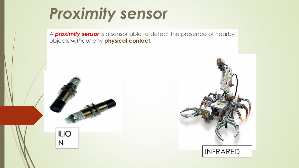
Proximity sensorA proximity sensor is a sensor able to detect the presence of nearby
objects without any physical contact.
INFRARED

A proximity sensor often emits an electromagnetic field or a beam
of electromagnetic radiation (infrared, for instance), and looks for
changes in the field or return signal.
The object being sensed is often referred to as the proximity sensor's
target. Different proximity sensor targets demand different sensors.
For example, a capacitive or photoelectric sensor might be suitable
for a plastic target; an inductive proximity sensor always requires a
metal target.
INDUCTIVE
CAPACITIVE

Types of PROXIMITY SENSOR
Capacitive
Inductive
Passive optical
Ultrasonic sensor
MAGNETIC
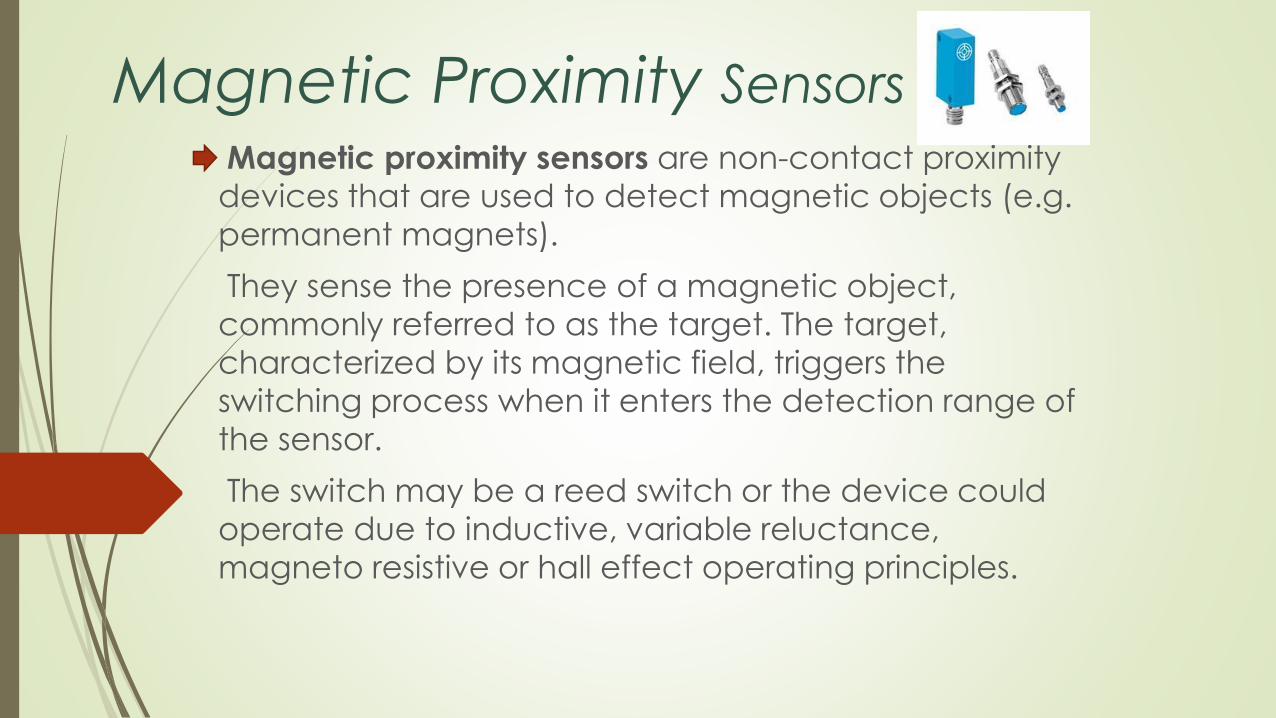
Magnetic Proximity Sensors
Magnetic proximity sensors are non-contact proximity
devices that are used to detect magnetic objects (e.g.
permanent magnets).
They sense the presence of a magnetic object,
commonly referred to as the target. The target,
characterized by its magnetic field, triggers the
switching process when it enters the detection range of
the sensor.
The switch may be a reed switch or the device could
operate due to inductive, variable reluctance,
magneto resistive or hall effect operating principles.

Sensors Specifications
Performance Criteria
• Rated operating distance is the critical distance at which switching takes place. It is important to choose a sensor that
will operate in the required sensing range. This could be
dictated by process requirements and mounting option.
• Repeatability is the distance within which the sensor repeatably switches. It is a measure of precision. Depending on
the application, precision could be an important design
criterion when selecting a sensor.
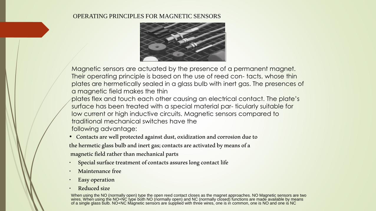
OPERATING PRINCIPLES FOR MAGNETIC SENSORS
• Contacts are well protected against dust, oxidization and corrosion due tothe hermetic glass bulb and inert gas; contacts are activated by means of amagnetic field rather than mechanical parts
• Special surface treatment of contacts assures long contact life• Maintenance free• Easy operation• Reduced size
Magnetic sensors are actuated by the presence of a permanent magnet.
Their operating principle is based on the use of reed con- tacts, whose thin
plates are hermetically sealed in a glass bulb with inert gas. The presences of
a magnetic field makes the thin
plates flex and touch each other causing an electrical contact. The plate’s
surface has been treated with a special material par- ticularly suitable for
low current or high inductive circuits. Magnetic sensors compared to
traditional mechanical switches have the
following advantage:
When using the NO (normally open) type the open reed contact closes as the magnet approaches. NO Magnetic sensors are twowires. When using the NO+NC type both NO (normally open) and NC (normally closed) functions are made available by means of a single glass bulb. NO+NC Magnetic sensors are supplied with three wires, one is in common, one is NO and one is NC
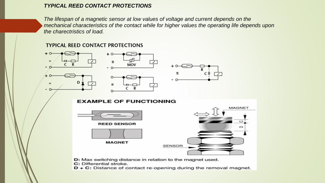
TYPICAL REED CONTACT PROTECTIONS
The lifespan of a magnetic sensor at low values of voltage and current depends on themechanical characteristics of the contact while for higher values the operating life depends upon the charectristics of load.

Magnetic Proximity SensorsExtremely small dimensions and high operating distances characterize these magnetic sensors in metallic case. To actuate sensor a magnetic is required.
Features:• High operating distance
• Threaded metallic case
• Protection degree of IP 67
• Hermetically sealed
• Compliant to the EMC directive
Dimensions: mm, 1" = 25.4 mm, 1 mm = .03937”
Table 1. Operating distances as a function of the magnetic unit(mm)
not to scale
4
Output NO NO/NCMagnetS3410 8 6S3411 20 17S3412 40 33
Output VA V A MODELNO 10 220 0.5 S3390 S3391 S3392 S3393
NO+NC 20 150 1 S3398 S3399 S3400 S3401Dimensions: mm1" = 25.4 mm1 mm = .03937”
Wiring
NO
Changeover, NO+NC
External Dimensions ∅ 6 mm M8 x1 M10 x 1 M12 x 1Operating Distance See Table 1Switching Frequency NO output = 230 Hz max/ NO+NC output = 250 Hz maxCase Nickel-Plated BrassProtection Degree IP 67Operating Temperature -25 to +100°C (-13 to +212°F)Output Connection Cable: 2 x 0.14 mm², L=2m

Rectangular Magnetic Proximity Sensors
To actuate sensor a magnetic is required.
Features:
•
•
•
•
High operating distance
Rectangular case
Protection degree of IP 67
Hermetically sealed
• Compliant to the EMC directive

CAPACITIVE
proximity sensor

Introduction
Capacitance is an electrical property which is created by applying
an electrical charge to two conductive objects with a gap between
them. The capacitance of a parallel plate capacitor is given by:
Where C is the capacitance, k is the permittivity of free
space constant, K is the dielectric constant of the material in the
gap, A is the area of the plates, and h is the distance between the
plates.
Capacitive sensor
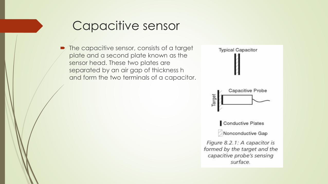
The capacitive sensor, consists of a target
plate and a second plate known as the
sensor head. These two plates are
separated by an air gap of thickness h
and form the two terminals of a capacitor.

Capacitive sensor
The guard ring
essentially moves the
distorted edges of the
electric field to the
outer edge of the
guard, significantly
improving the uniformity
of the electric field over
the sensor area and
extending its linearity.

Capacitive sensor
Sensitivity
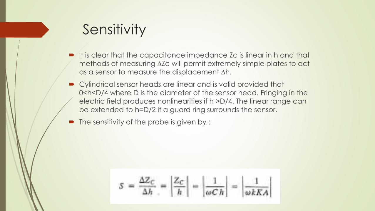
It is clear that the capacitance impedance Zc is linear in h and that
methods of measuring ∆Zc will permit extremely simple plates to act
as a sensor to measure the displacement ∆h.
Cylindrical sensor heads are linear and is valid provided that
0<h<D/4 where D is the diameter of the sensor head. Fringing in the
electric field produces nonlinearities if h >D/4. The linear range can
be extended to h=D/2 if a guard ring surrounds the sensor.
The sensitivity of the probe is given by :

Sensitivity
Sensitivity can be improved by reducing the area of the probe, however
the range of the probe is limited by linearity to about D/2.
Low frequency improves sensitivity but limits frequency response of the
instrument.
It is also important to note that the frequency of the ac power supply must
remain constant to maintain a stable calibration constant.
Advantages
It is non-contacting and can be used with any target material.
The sensor is extremely rugged and can be subjected to high shock loads
and intense vibratory environments.
Can be used at high temperature.
Sensitivity remains constant over a wide range of temperature.

Industrial application
Typical capacitive sensor construction shows two plates: one
connects to the oscillator (sensor electrodes), and the other is the
object being sensed, which is detected within the electrical field.
Industrial application
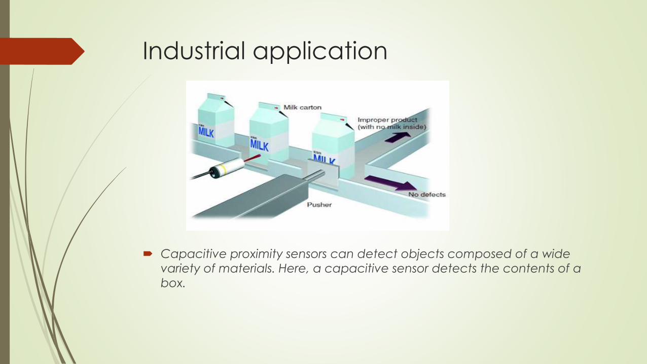
Capacitive proximity sensors can detect objects composed of a wide
variety of materials. Here, a capacitive sensor detects the contents of a
box.
Industrial application
A capacitive sensor functions like a typical capacitor. The metal plate in
the end of the sensor electrically connects to the oscillator, and the object
to be sensed acts as the second plate. When this sensor receives power,
the oscillator detects the external capacitance between the target and
the internal sensor plate. This arrangement completes the circuit and
provides the necessary feedback path for the output circuit to evaluate.
Capacitive sensors can detect many different kinds of objects. For
example, solids, liquids, or granular targets are all detectable (including
metals, water, wood, and plastic).

Inductance proximity sensors
Inductive proximity sensors operate under the electrical principle of
inductance. Inductance is the phenomenon where a fluctuating
current, which by definition has a magnetic component, induces an
electromotive force (emf) in a target object.
these are best used when your application calls for metallic target
sensing with a range that is within an inch of the sensing surface.

An inductive proximity sensor has four elements: coil, oscillator, trigger
circuit, and an output. The oscillator is an inductive capacitive tuned
circuit that creates a radio frequency. The electromagnetic field
produced by the oscillator is emitted from the coil away from the
face of the sensor. The circuit has just enough feedback from the
field to keep the oscillator going. When a metal target enters the
field, eddy currents circulate within the target. This causes a load on
the sensor, decreasing the amplitude of the electromagnetic field. As
the target approaches the sensor, the eddy currents increases,
increasing the load on the oscillator and further decreasing the
amplitude of the field.
The trigger circuit monitors the oscillator’s amplitude and at a
predetermined level switches the output state of the sensor from its
normal condition (on or off). As the target moves away from the
sensor, the oscillator’s amplitude increases. At a predetermined level
the trigger switches the output state of the sensor back to its normal
condition (on or off).


Eddy current sensor
An eddy current sensor measures distance between the sensor head and
an electrically conducting surface.sensor operation is based on eddy
currents that are induced at the conducting surface as magnetic flux lines
from the sensor intersect with the surface of the conducting material.
The magnetic flux lines are generated by the active coil in the sensor,which
is driven at a very high frequency(1 MHz).
The magnitude of the eddy current produced at the surface of the
conducting material is a function of the distance between the active coil
and the surface.the eddy currents increase as the distance decreases.


Changes in the eddy currents are sensed with an
impedance(inductance) bridge.two coils in the sensor are used for
two arms of the bridge. The other two arms are housed in the
associated electronic package.
The first coil in the sensor is the active coil and the second coil is
inactive or balance coil.active coil changes inductance with target
movement which is wired into the active arm of the bridge.thw
second coil is wired into an opposing arm of the same bridge,where it
serves as a compensating coil and cancel the effects of temperature
change.

The output from the impedance bridge is demodulated and
becomes the analog signal,which is linearly proportional to distance
between the sensor and the target.
The sensitivity of the sensor is dependent on the target material,with
higher sensitivity associated with higher conductivity materials.
Thus eddy current sensors are high output devices if the specimen is
non magnetic and from the graph it says that the sensitivity
decreases significantly if the specimen material is magnetic.


For aluminium the sensitivity is typically 100mV/mil(4mV/mm).
For non conducting,poorly conduting or magnetic materials,it is
possible to bond a thin film of aluminium foil to the surface of the target
at the location of the sensor to improve the sensitivity.the thickness of
the foil can be little as 0.7mm.

The effect of temperature on the output of the eddy current sensor is
small. The sensing head with with dual coils is temperature
compensated,however a small error can be produced by
temperature changes in the target material,since resistivity of the
target materil is a function of temperature.
So while measuring output we should even take care of sensitivity.

The range of eddy current sensor is controlled by the diameters of the
coils,with the larger sensors exhibiting the larger ranges.the range to
diameter is usually about 0.25.
linearity is typically better than 0.05 percent

Eddy-Current Sensor Advantages
Compared to other noncontact sensing technologies such as optical,
laser, and capacitive, high-performance eddy-current sensors have
some distinct advantages.
Tolerance of dirty environments
Not sensitive to material in the gap between the probe and target
Less expensive and much smaller than laser interferometers
Less expensive than capacitive sensors
Eddy-Current sensors are not a good choice in these conditions:
Extremely high resolution (capacitive sensors are ideal)
Large gap between sensor and target is required (optical and laser
are better)

The Eddy Current Sensor
Precision eddy current noncontact measuring systems have been used for
more than 30 years for displacement, vibration, thickness, alignment,
dimensioning, and parts sorting applications. All these can be classified as
variations on displacement because in each case the parameter being
measured is the distance from the target to the sensor. The differences lie in
the interpretation and implementation of the displacement data.
The fact that eddy current sensors do not require contact for measuring
displacement is quiet important.as a result of this feature,they are often
used in transducer systems for automatic control of dimensions in
fabrication process.
They are also applied extensively to determine thickness of organic
coatings that are non-conducting.


Ultrasonic Sensors

Ultrasonic sensors are based on measuring the properties of
sound waves with frequency above the human audible
range.
Systems typically use a transducer which generates
sound waves in the ultrasonic range, above 18 kHz, by
turning electrical energy into sound, then upon receiving
the echo turn the sound waves into electrical energy
which can be measured.
Ultrasonic sensors are non-intrusive in that they do not
require physical contact with their target, and can
detect certain clear or shiny targets otherwise obscured to some vision-based sensors.
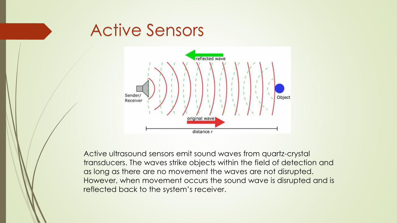
Active Sensors
Active ultrasound sensors emit sound waves from quartz-crystal
transducers. The waves strike objects within the field of detection and
as long as there are no movement the waves are not disrupted.
However, when movement occurs the sound wave is disrupted and is
reflected back to the system’s receiver.
Passive Ultrasonic Motion Sensors
Passive sensors operate on the principle of sounds such as breaking glass or metal striking metal to trigger alarms.
These sounds produce waves detected by the sensors
that, like the active sensors, relay them to electronic
control units to determine if the sound wave pattern falls
within established normal parameters.
Benefits of High Frequency
Uninterrupted coverage
Electronically adjustable reach
Detection through glass, wood, walls etc.
“Invisible” sensor that can be integrated in lights
Can be concealed behind trim panels
Uninterrupted signal propagation
Good quality of detection, even in long rooms, stairwells etc.
Extremely fast detection of the smallest of movements
Operates irrespective of ambient temperature and temperature
of objects
Reach, twilight threshold and light ‘ON’ duration can be set to suit
individual needs

Applications
a)Bottle Counting on Drink Filling Machines

Thru-beam sensors
Individual detection of conveyed bottles is normally too fast for
sensing by ultrasonic sensors. The bottles pass the sensor too
quickly and the gaps between the bottles are often too small.
For this reason, ultrasonic thru-beam sensors are particularly
suitable for bottle counting.
The use of hot steam and chemicals for machine cleaning in
these applications requires ultrasonic thru-beam sensors with a
high degree of chemical resistance.
Even in areas with strong steam generation, reliable detection
of bottles is guaranteed with ultrasonic thru-beam sensors.

b) Vehicle Detection in Barrier Systems

In car parking lots and parking garages, entry is controlled using
barrier systems. The barrier must not be lowered when there is a
vehicle underneath. Ultrasonic sensors are particularly suitable
for controlling this process. They detect objects regardless of
vehicle type or color and monitor the entire area below the
barrier.
When mounting and aligning the sensors, ensure that the
devices are installed at a sufficient distance from the ground (if
necessary, angled slightly upwards)

Optical Proximity
Sensors
Working Principle
An optical proximity sensor offers non-contact sensing of
almost any object up to a range of 10 meters. It includes a
light source, (usually an LED in either infrared or visible light
spectrum) and a detector (photodiode). The light source
generates light of a frequency that the light sensor is best able
to detect, and that is not likely to be generated by other
nearby sources. Infra-red light is used in most optical sensors. To make the light sensing system more foolproof, most optical
proximity sensor light sources pulse the infra-red light on and
off at a fixed frequency.
Due to the high intensity infra-red energy beam, these sensors
have major advantages over other opto-electronic systems when employed in dusty enviroments.
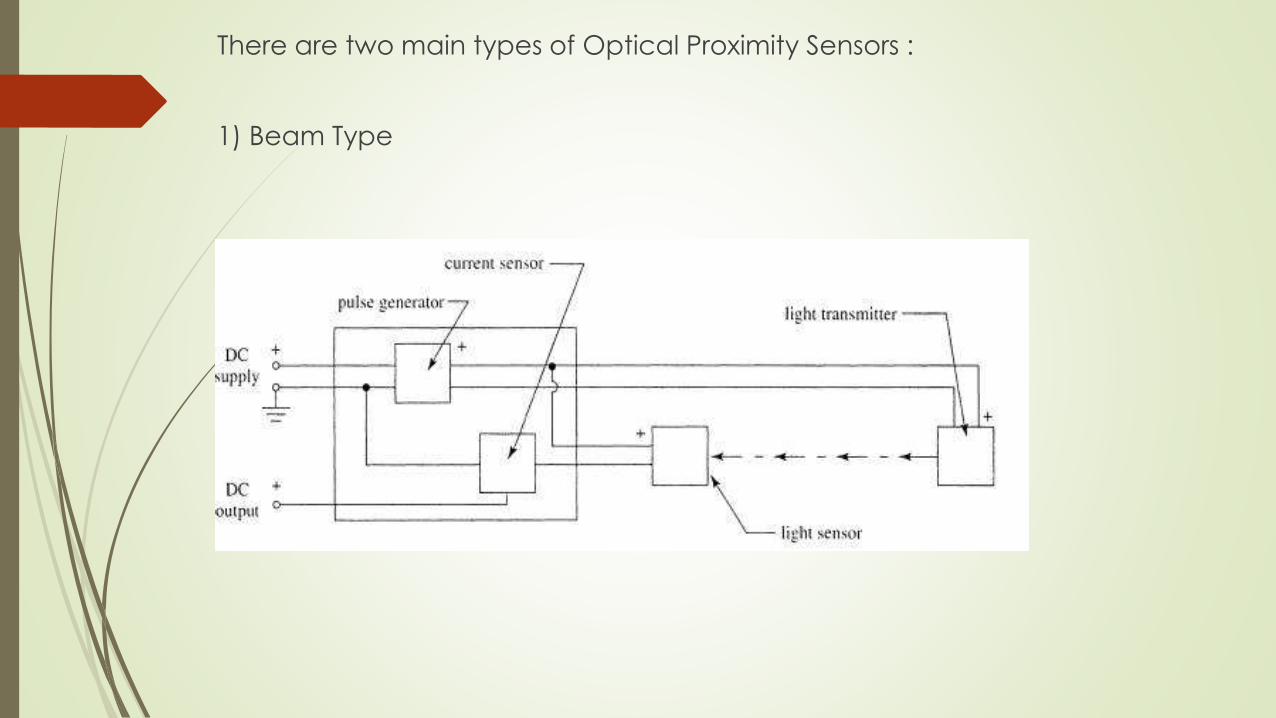
There are two main types of Optical Proximity Sensors :
1) Beam Type

2) Retro Reflective Type

Name Advantages Disadvantages
Beam Type
•Most accurate
•Longest sensing
range
•Very reliable
•Must install at two
points on system:
emitter and receiver
•Costly - must
purchase both
emitter and receiver
Reflective Type
• Slightly less
accurate than
through-beam
•Very reliable
•Must install at two
points on system:
sensor and reflector
•Sensing range less
than beam type
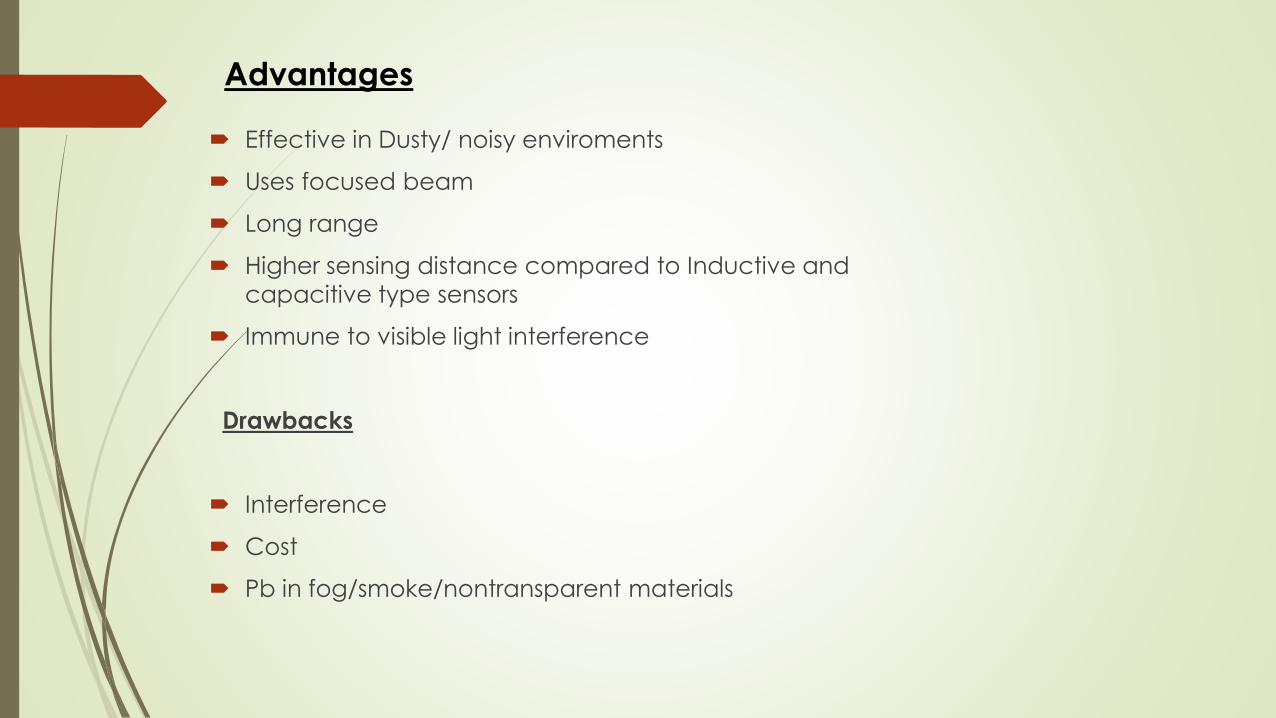
Effective in Dusty/ noisy enviroments
Uses focused beam
Long range
Higher sensing distance compared to Inductive and
capacitive type sensors
Immune to visible light interference
Drawbacks
Interference
Cost
Pb in fog/smoke/nontransparent materials
Advantages

Lift door mechanisms
Pipeline monitoring, wind turbine blade monitoring, fuel tank
and ship hull monitoring, power line monitoring etc.
Component positioning sensing in Electronic industry
Security and safety applications in presses
Colour sensing applications
Counting of bottles/containers in factories etc.
General Applications
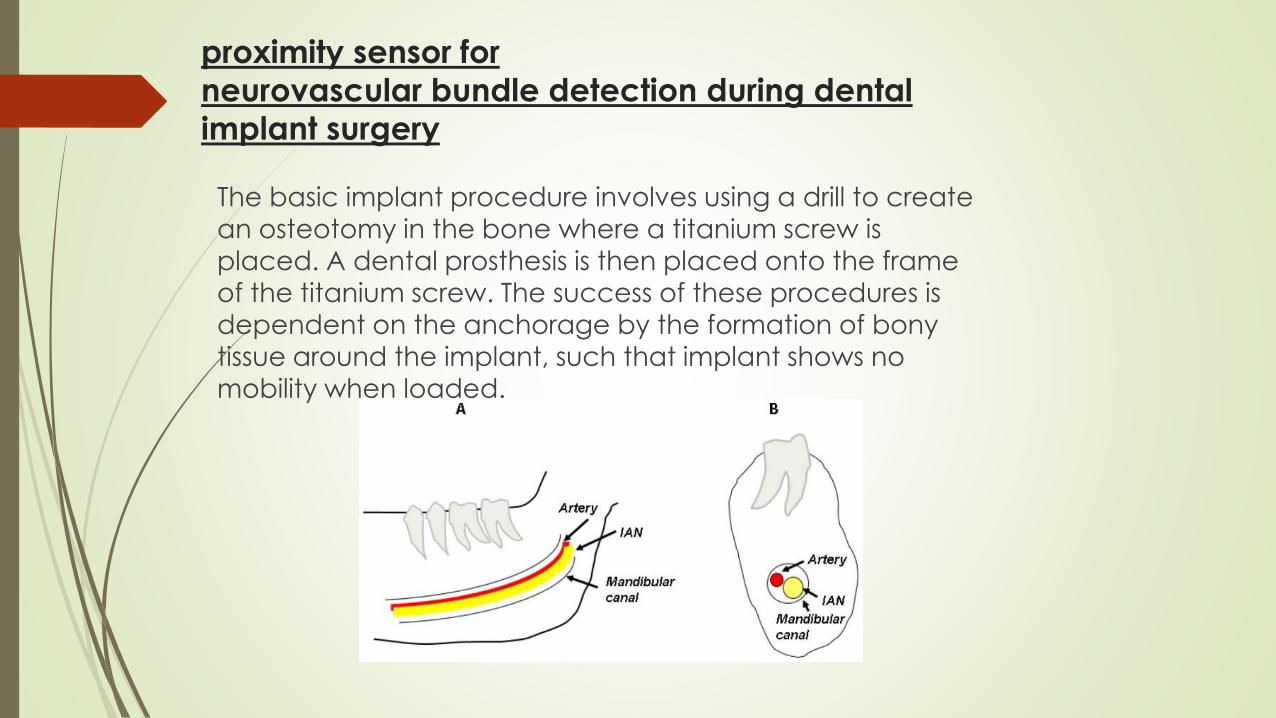
proximity sensor for
neurovascular bundle detection during dental
implant surgery
The basic implant procedure involves using a drill to create
an osteotomy in the bone where a titanium screw is
placed. A dental prosthesis is then placed onto the frame
of the titanium screw. The success of these procedures is
dependent on the anchorage by the formation of bony
tissue around the implant, such that implant shows no mobility when loaded.
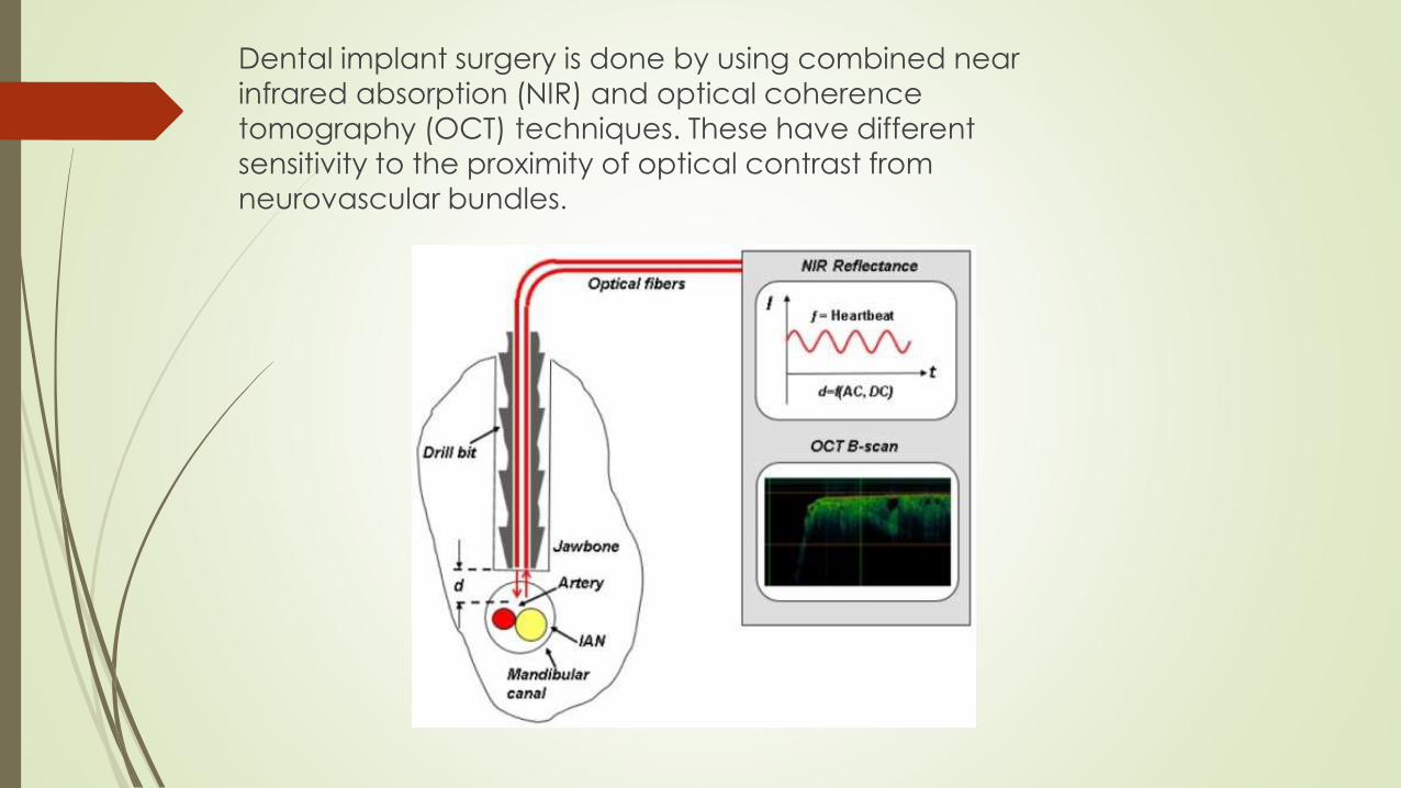
Dental implant surgery is done by using combined near infrared absorption (NIR) and optical coherence
tomography (OCT) techniques. These have different
sensitivity to the proximity of optical contrast from
neurovascular bundles.

Implant depth is determined by the
surgeon when drilling the channel in
the mandible. The depth when drilling
a dental implant channel within the
mandible is limited by the risk of
breaching the mandibular canal that
contains a neurovascular bundle
including the inferior alveolar nerve
(IAN), which is the mental nerve
providing sensory enervation to the
lower lips and chin.
Loss of sensation in the anterior
mandible, such as numbness to the
lower lip and chin, can occur due to
the disruption of the IAN.
The reported incidence of nerve
injury from implant placement is as
high as 44%, with 73% of dentists
encountering neurosensory
impairment within their practice.

The medical complications that could be avoided by using this
device are
(i) Vertical bone grafting
(ii) Nerve lateralization (moving the nerve out of the jaw) which
causes a high risk of nerve injury and sometimes permanent
damage.

Thank you !


![[FESTO] Proximity Sensors - Textbook](https://static.documents.pub/doc/80x56/552b9acc550346ef478b4759/festo-proximity-sensors-textbook.jpg)


